WO2017149660A1 - 空調システム - Google Patents
空調システム Download PDFInfo
- Publication number
- WO2017149660A1 WO2017149660A1 PCT/JP2016/056266 JP2016056266W WO2017149660A1 WO 2017149660 A1 WO2017149660 A1 WO 2017149660A1 JP 2016056266 W JP2016056266 W JP 2016056266W WO 2017149660 A1 WO2017149660 A1 WO 2017149660A1
- Authority
- WO
- WIPO (PCT)
- Prior art keywords
- controller
- terminal
- detection data
- air conditioning
- indoor unit
- Prior art date
- Legal status (The legal status is an assumption and is not a legal conclusion. Google has not performed a legal analysis and makes no representation as to the accuracy of the status listed.)
- Ceased
Links
Images


Classifications
-
- F—MECHANICAL ENGINEERING; LIGHTING; HEATING; WEAPONS; BLASTING
- F24—HEATING; RANGES; VENTILATING
- F24F—AIR-CONDITIONING; AIR-HUMIDIFICATION; VENTILATION; USE OF AIR CURRENTS FOR SCREENING
- F24F11/00—Control or safety arrangements
- F24F11/30—Control or safety arrangements for purposes related to the operation of the system, e.g. for safety or monitoring
- F24F11/49—Control or safety arrangements for purposes related to the operation of the system, e.g. for safety or monitoring ensuring correct operation, e.g. by trial operation or configuration checks
-
- F—MECHANICAL ENGINEERING; LIGHTING; HEATING; WEAPONS; BLASTING
- F24—HEATING; RANGES; VENTILATING
- F24F—AIR-CONDITIONING; AIR-HUMIDIFICATION; VENTILATION; USE OF AIR CURRENTS FOR SCREENING
- F24F11/00—Control or safety arrangements
- F24F11/30—Control or safety arrangements for purposes related to the operation of the system, e.g. for safety or monitoring
-
- F—MECHANICAL ENGINEERING; LIGHTING; HEATING; WEAPONS; BLASTING
- F24—HEATING; RANGES; VENTILATING
- F24F—AIR-CONDITIONING; AIR-HUMIDIFICATION; VENTILATION; USE OF AIR CURRENTS FOR SCREENING
- F24F11/00—Control or safety arrangements
- F24F11/50—Control or safety arrangements characterised by user interfaces or communication
- F24F11/52—Indication arrangements, e.g. displays
-
- F—MECHANICAL ENGINEERING; LIGHTING; HEATING; WEAPONS; BLASTING
- F24—HEATING; RANGES; VENTILATING
- F24F—AIR-CONDITIONING; AIR-HUMIDIFICATION; VENTILATION; USE OF AIR CURRENTS FOR SCREENING
- F24F11/00—Control or safety arrangements
- F24F11/50—Control or safety arrangements characterised by user interfaces or communication
- F24F11/56—Remote control
- F24F11/57—Remote control using telephone networks
-
- F—MECHANICAL ENGINEERING; LIGHTING; HEATING; WEAPONS; BLASTING
- F24—HEATING; RANGES; VENTILATING
- F24F—AIR-CONDITIONING; AIR-HUMIDIFICATION; VENTILATION; USE OF AIR CURRENTS FOR SCREENING
- F24F11/00—Control or safety arrangements
- F24F11/50—Control or safety arrangements characterised by user interfaces or communication
- F24F11/56—Remote control
- F24F11/58—Remote control using Internet communication
-
- F—MECHANICAL ENGINEERING; LIGHTING; HEATING; WEAPONS; BLASTING
- F24—HEATING; RANGES; VENTILATING
- F24F—AIR-CONDITIONING; AIR-HUMIDIFICATION; VENTILATION; USE OF AIR CURRENTS FOR SCREENING
- F24F11/00—Control or safety arrangements
- F24F11/62—Control or safety arrangements characterised by the type of control or by internal processing, e.g. using fuzzy logic, adaptive control or estimation of values
- F24F11/63—Electronic processing
- F24F11/64—Electronic processing using pre-stored data
-
- G—PHYSICS
- G05—CONTROLLING; REGULATING
- G05B—CONTROL OR REGULATING SYSTEMS IN GENERAL; FUNCTIONAL ELEMENTS OF SUCH SYSTEMS; MONITORING OR TESTING ARRANGEMENTS FOR SUCH SYSTEMS OR ELEMENTS
- G05B19/00—Program-control systems
- G05B19/02—Program-control systems electric
- G05B19/04—Program control other than numerical control, i.e. in sequence controllers or logic controllers
- G05B19/042—Program control other than numerical control, i.e. in sequence controllers or logic controllers using digital processors
-
- F—MECHANICAL ENGINEERING; LIGHTING; HEATING; WEAPONS; BLASTING
- F24—HEATING; RANGES; VENTILATING
- F24F—AIR-CONDITIONING; AIR-HUMIDIFICATION; VENTILATION; USE OF AIR CURRENTS FOR SCREENING
- F24F11/00—Control or safety arrangements
- F24F11/30—Control or safety arrangements for purposes related to the operation of the system, e.g. for safety or monitoring
- F24F11/32—Responding to malfunctions or emergencies
-
- F—MECHANICAL ENGINEERING; LIGHTING; HEATING; WEAPONS; BLASTING
- F24—HEATING; RANGES; VENTILATING
- F24F—AIR-CONDITIONING; AIR-HUMIDIFICATION; VENTILATION; USE OF AIR CURRENTS FOR SCREENING
- F24F11/00—Control or safety arrangements
- F24F11/50—Control or safety arrangements characterised by user interfaces or communication
- F24F11/56—Remote control
-
- F—MECHANICAL ENGINEERING; LIGHTING; HEATING; WEAPONS; BLASTING
- F24—HEATING; RANGES; VENTILATING
- F24F—AIR-CONDITIONING; AIR-HUMIDIFICATION; VENTILATION; USE OF AIR CURRENTS FOR SCREENING
- F24F2110/00—Control inputs relating to air properties
- F24F2110/10—Temperature
-
- F—MECHANICAL ENGINEERING; LIGHTING; HEATING; WEAPONS; BLASTING
- F24—HEATING; RANGES; VENTILATING
- F24F—AIR-CONDITIONING; AIR-HUMIDIFICATION; VENTILATION; USE OF AIR CURRENTS FOR SCREENING
- F24F2120/00—Control inputs relating to users or occupants
- F24F2120/10—Occupancy
- F24F2120/12—Position of occupants
-
- G—PHYSICS
- G05—CONTROLLING; REGULATING
- G05B—CONTROL OR REGULATING SYSTEMS IN GENERAL; FUNCTIONAL ELEMENTS OF SUCH SYSTEMS; MONITORING OR TESTING ARRANGEMENTS FOR SUCH SYSTEMS OR ELEMENTS
- G05B2219/00—Program-control systems
- G05B2219/20—Pc systems
- G05B2219/26—Pc applications
- G05B2219/2614—HVAC, heating, ventillation, climate control
Definitions
- the present invention relates to an air conditioning system, and relates to an air conditioning system in which an air conditioner and a controller communicate with each other by a first communication method, and a terminal other than the controller and the controller communicates by a second communication method.
- a controller of a conventional air conditioning system is connected to an air conditioner via wiring, stores data such as an operation history and a failure code, and can transmit the data to a terminal such as a mobile phone. Yes (see, for example, Patent Document 1). With the technique described in Patent Document 1, this data is transmitted from a terminal such as a mobile phone to a service store, and the service store can grasp whether the air conditioner needs to be inspected.
- the present invention has been made to solve the above-described problems, and an object of the present invention is to provide an air conditioning system capable of more precisely grasping whether or not the air conditioner needs to be inspected. Yes.
- An air conditioning system communicates with an indoor unit including an indoor unit including a radiation temperature sensor that detects a radiation temperature of an outdoor unit and an air-conditioning target space, and acquires detection data of the radiation temperature sensor.
- a controller and a terminal that communicates with the controller and acquires detection data from the controller are provided. The terminal detects and outputs a change in the detection data.
- the air conditioning system according to the present invention has the above-described configuration, it is possible to grasp in detail whether or not the air conditioner needs to be inspected.
- FIG. 1A is a system configuration diagram of an air conditioning system 500 according to the present embodiment.
- FIG. 1B is a diagram showing a refrigerant circuit and the like of the air conditioning apparatus 100 of the air conditioning system 500 according to the present embodiment.
- the air conditioning system 500 includes an air conditioner 100, a controller 1, and a terminal 8.
- the air conditioning system 500 may include a service store 90 in addition to these.
- the terminal 8 is a mobile phone.
- the terminal 8 is not limited to a mobile phone, but may be a PC (personal computer) or the like, and is not particularly limited.
- the air conditioner 100 includes an indoor unit 5 including an outdoor unit 7 and a radiation temperature sensor 9 that detects the radiation temperature of the air-conditioning target space.
- the controller 1 communicates with the indoor unit 5 and acquires (receives) detection data of the radiation temperature sensor 9.
- the terminal 8 communicates with the controller 1 and acquires (receives) detection data from the controller 1.
- the detection data is radiation temperature data of the air conditioning target space.
- the terminal 8 creates image data indicating the temperature distribution of the air conditioning target space from the detection data.
- Controller 1 includes main controller A, sub-controller B and sub-controller C.
- the controller 1 can be composed of, for example, a remote controller.
- the controller 1 is connected so as to communicate with the four indoor units 5.
- the sub-controller B is also connected so that it can communicate with the four indoor units 5.
- the sub controller C is connected so as to be able to communicate with the two indoor units 5.
- the indoor units 5 communicate with each other using the first communication method.
- the indoor unit 5 and the controller 1 also communicate with each other using the first communication method.
- the indoor units 5 are connected to each other by a wiring L1.
- the indoor unit 5 and the controller 1 are also connected by the wiring L1.
- a dedicated line for connecting the indoor unit 5 and the controller 1 is used.
- the operation power supply of the controller 1 is supplied from the indoor unit 5.
- Controller 1 and terminal 8 communicate with each other by the second communication method.
- the controller 1 and the terminal 8 communicate by wireless L2.
- the second communication method can employ short-range wireless communication.
- the power supply capability to the controller 1 of the indoor unit 5 can be reduced by employing short-range wireless communication.
- the outdoor unit 7 and the indoor unit 5 communicate using the third communication method.
- the outdoor unit 7 and the indoor unit 5 are connected by a wiring L3.
- the wiring L3 has a configuration including an AC power supply line and one communication line, and a configuration connected using a dedicated line.
- the former configuration is easier to construct than the latter configuration, but the communication distance is short and the communication speed is low. For this reason, the number of indoor units 5 connected to one outdoor unit 7 is about four at the maximum, for example.
- the wiring L3 includes an AC power supply line and one communication line. In the present embodiment, the case where four outdoor units 5 are connected to the outdoor unit 7 will be described as an example.
- the terminal 8 and the service store 90 communicate with each other using the fourth communication method.
- the terminal 8 and the service store 90 may communicate wirelessly or may be connected by wiring.
- the indoor unit 5 is equipped with a radiation temperature sensor 9 that detects the radiation temperature of the air-conditioning target space.
- the indoor unit 5 transmits detection data of the radiation temperature sensor 9 and the like to the controller 1.
- the indoor unit 5 also receives data and the like related to the operation instruction of the air conditioning apparatus 100 from the controller 1.
- the radiation temperature sensor 9 detects human and floor temperatures.
- Each indoor unit 5 transmits the detection data of the radiation temperature sensor 9 to the controller 1 using the first communication method.
- the controller 1 transmits the detection data of the radiation temperature sensor 9 to the terminal 8 using the second communication method.
- the terminal 8 receives the detection data and detects a change in the detection data. And the terminal 8 will output that it detected, if the change of detection data is detected.
- output refers to displaying image data of the temperature distribution of the air-conditioning target space on the display unit 20 of the terminal 8 in the present embodiment.
- the present invention is not limited to this. For example, when a change in detection data is detected, a lighting lamp attached to the terminal 8 may be turned on. Further, when a change in the detected data is detected, the terminal 8 may be notified by voice.
- Detected data is transmitted to the controller 1 after the radiation temperature sensor 9 has rotated 360 degrees. Next, when the rotation is performed 360 degrees, the data is transmitted to the controller 1.
- the data to be transmitted is a value (array) read by the radiation temperature sensor 9.
- the controller 1 transmits the array data to the terminal 8. It is possible to control whether or not to transmit the array data to the terminal 8 by the user setting transmission permission to the controller 1.
- the controller 1 can transmit data related to operation instructions of the air conditioner 100 to the indoor unit 5.
- the controller 1 can receive detection data of the air-conditioning target space from the indoor unit 5. Further, the controller 1 can transmit detection data of the air-conditioning target space to the terminal 8.
- the controller 1 can receive data relating to driving instructions from the terminal 8.
- the terminal 8 can transmit data related to the operation instruction of the air conditioner 100 to the controller 1. Further, the terminal 8 can receive detection data of the air-conditioning target space from the controller 1. The terminal 8 has a function of detecting a change in detection data of the air-conditioning target space received from the controller 1. Further, the terminal 8 can display a mesh diagram (image data) indicating the temperature distribution of the air conditioning target space from the detection data of the air conditioning target space received from the controller 1 (see FIG. 2).
- the air conditioning apparatus 100 includes an indoor unit 5 and an outdoor unit 7.
- the air conditioner 100 includes a compressor 51 that compresses the refrigerant, and a flow path switching valve 52 that switches the refrigerant flow path.
- the air conditioner 100 includes an indoor heat exchanger 53 that functions as an evaporator or a condenser, an outdoor heat exchanger 55 that functions as a condenser or an evaporator, and an indoor fan that supplies air to the indoor heat exchanger 53. 53A and an outdoor fan 55A for supplying air to the outdoor heat exchanger 55.
- the air conditioning apparatus 100 includes a throttle device 54 that depressurizes the refrigerant.
- the indoor unit 5 is equipped with an indoor heat exchanger 53 and an indoor blower 53A.
- the outdoor unit 7 includes a compressor 51, a flow path switching valve 52, an outdoor heat exchanger 55, an expansion device 54, and an outdoor blower 55A. By switching the flow path switching valve 52, the air conditioner 100 can switch between the cooling operation and the heating operation. In FIG. 1B, the state at the time of heating operation is shown.
- FIG. 1C is a functional block diagram of an air conditioning system 500 according to the present embodiment.
- FIG. 2 is a mesh diagram (image data) of air conditioning system 500 according to the present embodiment. With reference to FIG. 1C and FIG. 2, the function of the air conditioning apparatus 100, the controller 1, and the terminal 8 is demonstrated.
- the indoor unit 5 of the air conditioner 100 includes an operation control unit 10, a determination unit 11, a test operation switch SW, a memory Me, a reception unit 12, and a transmission unit 13.
- the operation control unit 10 controls various actuators based on the determination result of the determination unit 11 and the data related to the operation instruction transmitted from the controller 1.
- the operation control unit 10 controls, for example, the rotational speed of the outdoor fan 55A and the indoor fan 53A, the opening degree of the expansion device 54, the frequency of the compressor 51, the switching of the flow path switching valve 52, and the like. Further, the operation control unit 10 controls the various actuators so that predetermined operations are performed when the determination unit 11 determines that the test operation switch SW has been pressed.
- the determination unit 11 determines, for example, whether any part of the air-conditioning target space is cold or hot based on the detection data of the radiation temperature sensor 9. Moreover, the determination part 11 determines whether the test run switch SW is pushed.
- the trial operation switch SW is attached to the indoor unit 5, for example.
- the air conditioner 100 performs a predetermined operation.
- This operation includes, for example, a blowing operation that moves only the indoor fan 53A. Further, this operation includes a cooling operation or a heating operation in which the compressor 51, the indoor fan 53A, the outdoor fan 55A, the expansion device 54, the flow path switching valve 52, and the like are operated.
- the memory Me stores various data.
- the memory Me stores, for example, detection data detected by the radiation temperature sensor 9.
- the memory Me includes operation data such as a set temperature of the air conditioner 100, data indicating the model of the air conditioner 100, operation data such as an operation time of the air conditioner 100, and the compressor 51 of the outdoor unit 7.
- Operation data such as current consumption and rotation speed, a code representing the cause of failure of the air conditioner 100, and data such as outside air temperature can also be stored.
- the receiving unit 12 receives data from the controller 1.
- the transmission unit 13 transmits data to the controller 1.
- the controller 1 gives instructions to the air conditioner 100 for operations such as cooling operation and heating, when operated by a user or the like.
- the controller 1 stores a plurality of the detection data, and transmits the stored detection data in response to a request from the terminal 8.
- the controller 1 includes a transmission unit 14 that transmits data to the reception unit 12 of the air conditioning apparatus 100 and a reception unit 15 that receives data from the transmission unit 13 of the air conditioning apparatus 100.
- the controller 1 also includes a determination unit 22 that determines whether or not a test operation instruction has been received from the terminal 8, and a memory 23 that stores various data. Note that the transmission unit 14 of the controller 1 can also transmit data to the terminal 8, and the reception unit 15 can also receive data from the terminal 8.
- the controller 1 When the controller 1 receives the operation instruction from the terminal 8, the controller 1 transmits the detection data before the test operation acquired in advance from the indoor unit 5 to the terminal 8, and then causes the air conditioner 100 to execute the test operation. Moreover, the controller 1 will acquire the detection data after performing test operation from the indoor unit 5, if the air conditioning apparatus 100 performs test operation. Furthermore, the controller 1 transmits detection data after the trial operation acquired from the indoor unit 5 to the terminal 8. Note that the terminal 8 detects and outputs a change between the detection data before the trial run and the detection data after the trial run.
- the terminal 8 includes a receiving unit 16 that receives data from the controller 1 and a transmitting unit 17 that transmits data to the controller 1.
- the terminal 8 also includes a change detection unit 18 that detects a change in detection data transmitted from the controller 1 and a data creation unit 19 that creates a mesh diagram based on the detection data received from the reception unit 16.
- the terminal 8 is a mobile phone (mobile terminal) such as a smartphone, and includes a display unit 20. Further, the terminal 8 includes a memory 21 for storing various data.
- the terminal 8 can receive an instruction to start a test operation to the air conditioner 100 and can transmit the instruction data to the air conditioner 100 via the controller 1 by being operated by a service person.
- the change detection unit 18 has a function of comparing detection data acquired in order and detecting whether there is a change.
- the change detection unit 18 detects whether or not the air-conditioning apparatus 100 is properly operated from the difference in the detection data of the radiation temperature sensor 9 or the difference in the difference in the detection data.
- the data creation unit 19 has a function of using the detection data of the radiation temperature sensor 9 received from the controller 1 by the receiving unit 16 as image data.
- This image data is displayed on the display unit 20 as a mesh diagram as shown in FIG.
- This image data shows the temperature distribution in the air-conditioning target space. In FIG. 2, the higher the temperature, the darker the color.
- the terminal 8 includes a memory 21 and can store a plurality of image data.
- the data creation unit 19 also has a function of arranging a plurality of image data generated from the detection data in the order received from the controller 1. That is, the display unit 20 can display the image data created by the data creation unit 19 in a time series as a mesh diagram.
- the time series display may be a list display or a slide show display.
- the display unit 20 can display the mesh diagram created by the data creation unit 19. Thereby, the service person can grasp the temperature distribution of the air-conditioning target space by looking at the terminal 8.
- control part 10 and the determination part 11 can be comprised with a control apparatus.
- the change detection unit 18 and the data creation unit 19 can also be configured by a control device.
- the control device is composed of, for example, dedicated hardware or a CPU (Central Processing Unit, central processing unit, processing unit, arithmetic unit, microprocessor, microcomputer, processor, etc.) that executes a program stored in a memory. Is done.
- the control device is dedicated hardware, the control device may be, for example, a single circuit, a composite circuit, an application specific integrated circuit (ASIC), a field-programmable gate array (FPGA), or a combination of these. Applicable.
- Each functional unit realized by the control device may be realized by individual hardware, or each functional unit may be realized by one piece of hardware.
- each function executed by the control device is realized by software, firmware, or a combination of software and firmware.
- Software and firmware are described as programs and stored in a memory.
- the CPU implements each function of the control device by reading and executing the program stored in the memory.
- a nonvolatile or volatile semiconductor memory such as a RAM, a ROM, a flash memory, an EPROM, or an EEPROM can be adopted as the memory.
- a part of the functions of the control device may be realized by dedicated hardware, and a part may be realized by software or firmware.
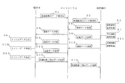
- FIG. 3 is a sequence diagram of air conditioning system 500 according to the present embodiment.
- the terminal 8 transmits the request instruction data of the detection data and the trial operation instruction data to the controller 1 (S1).
- the controller 1 transmits the request instruction data and the trial operation instruction data received from the terminal 8 to the indoor unit 5 (S2).
- the operation control unit 10 controls various actuators based on the test operation instruction data (S3).
- the air conditioning apparatus 100 operates the indoor blower 53A in order to perform the blowing operation.
- the operation control unit 10 controls the motor of the radiation temperature sensor 9 based on the request instruction data.
- the radiation temperature sensor 9 is rotated 360 °.
- the radiation temperature sensor 9 acquires detection data in the range of 360 °.
- the indoor unit 5 Since the indoor unit 5 has received the request instruction data, the indoor unit 5 transmits detection data to the controller 1 (S4).
- the controller 1 transmits the detection data received from the indoor unit 5 to the terminal 8 (S5).
- the data creation unit 19 of the terminal 8 generates image data (S6).
- the indoor unit 5 has received the trial operation instruction data in S2, and performs the cooling operation following the air blowing operation (S7).
- the set temperature for the cooling operation is, for example, 25 degrees.
- the indoor unit 5 has received the request instruction data in S2, and rotates the radiation temperature sensor 9 by 360 °. Thereby, the radiation temperature sensor 9 acquires detection data in the range of 360 degrees. Since the indoor unit 5 has received the request instruction data, the indoor unit 5 transmits the detection data to the controller 1 (S8).
- the controller 1 transmits the detection data received from the indoor unit 5 to the terminal 8 (S9).
- the data creation unit 19 of the terminal 8 generates image data (S6).
- the indoor unit 5 has received the trial operation instruction data in S2, and performs the heating operation following the cooling operation (S11).
- the preset temperature of heating operation is 25 degree
- the radiation temperature sensor 9 is rotated 360 °. Thereby, the radiation temperature sensor 9 acquires detection data in the range of 360 degrees.
- the indoor unit 5 has received the request instruction data, and the indoor unit 5 transmits the detection data to the controller 1 (S12).
- the controller 1 transmits the detection data received from the indoor unit 5 to the terminal 8 (S13).
- the data creation unit 19 of the terminal 8 generates image data (S14).
- the terminal 8 Since the terminal 8 has acquired the detection data of the trial operation of the air conditioning apparatus 100, the terminal 8 transmits the operation end instruction data to the controller 1 (S15).
- the controller 1 transmits the operation end instruction data received from the terminal 8 to the indoor unit 5 (S16).
- the controller 1 sequentially transmits the detection data (array data) received from the indoor unit 5 to the terminal 8.
- the control content for transmitting detection data to the controller 1 before the trial operation switch SW is turned on and the trial operation switch SW is turned on is omitted.
- the indoor unit 5 may transmit the detection data held before the trial operation switch SW is turned on to the controller 1 before S3, and the controller 1 may transmit the detection data to the terminal 8. .
- the change detection unit 18 of the terminal 8 compares the detection data acquired in order and detects whether there is a change. For example, if the change is larger than a predetermined value, the change detection unit 18 can detect that the air conditioner 100 is not operating properly.
- the detection result of the change detection part 18 is shown on the display part 20, for example, and is transmitted to the service store 90.
- the terminal 8 converts the array data into image data and displays it on the display unit 20.
- the service person can confirm the change of the radiation temperature of air-conditioning object space visually by performing a slide show of the image display. That is, the service person can confirm the change in the radiation temperature by viewing the mesh diagram on the display unit 20 as well as the detection result of the change detection unit 18.
- the terminal 8 such as a smartphone instead of the controller 1, restrictions on the CPU speed, memory capacity, etc. are relaxed. That is, the display of the image data and the analysis of the detection data can be accelerated, and the data storage of the image data and the detection data is easy.
- the value obtained by dividing the data amount of the radiation temperature sensor 9 by the data acquisition interval is a value sufficiently smaller than the speed at which the indoor unit 5 communicates with the controller 1 and the speed at which the controller 1 communicates with the terminal 8.
- the terminal 8 of the air conditioning system 500 detects and outputs a change between the detection data before the trial run and the detection data after the trial run.
- the trial operation is performed, for example, when the air conditioner 100 is repaired, inspected, installed, or replaced.
- the output of the terminal 8 is displayed (displayed or displayed) such that there is a portion that is difficult to cool in the air conditioning target space, there is a portion that is difficult to warm in the air conditioning target space, or the temperature distribution in the air conditioning target space is uneven. (Sound) can notify service personnel.
- the output of the terminal 8 is a display, for example, the terminal 8 displays a portion of the air-conditioning target space that is difficult to cool.
- the air-conditioning apparatus 100 is operated without any problems after the air-conditioning apparatus 100 has been repaired, inspected, installed, or replaced, the air-conditioning apparatus 100 is actually installed or defective.
- the above-described problems may occur due to a lack of 100 capabilities.
- the terminal 8 can output this failure to notify the service person. For this reason, the service person who has the terminal 8 easily grasps whether further repair or inspection is necessary on the spot or whether the air conditioner 100 itself needs to be replaced because it is insufficient. can do.
- the service store can also acquire radiation temperature data transmitted from the terminal 8 and easily grasp whether further repair or inspection is necessary. As described above, in the air conditioning system 500 according to the present embodiment, it is possible to grasp in detail whether or not the air conditioning apparatus 100 needs repair, inspection, or replacement.
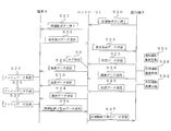
- FIG. 4 is a modification of the sequence diagram of air conditioning system 500 according to the present embodiment.
- the trial operation instruction data from the terminal 8 is a trigger for starting the trial operation.
- the trial operation switch SW provided in the indoor unit 5 is the trigger for starting the trial operation. ing.
- the indoor unit 5 includes a test operation switch SW that causes the air conditioner 100 to perform a test operation. Then, when the trial operation switch SW is turned on, the indoor unit 5 transmits the detection data held before the trial operation switch SW is turned on to the controller 1. Moreover, the indoor unit 5 transmits the detection data acquired after starting the test operation to the controller 1 after a certain time has elapsed since the start of the test operation. The terminal 8 detects and outputs a change between the detection data that the test operation switch SW had before being turned on and the detection data acquired after the start of the test operation. In the conventional air conditioner, it is not necessary to transmit various data from the indoor unit to the controller even if the trial operation switch is turned on.
- the detection data is transmitted from the indoor unit 5 to the controller 1 so that the detection data can be transmitted to the terminal 8 and the terminal 8 can confirm whether or not the above-described problems are present.
- switch pressing data is transmitted from the indoor unit 5 to the controller 1 (S20).
- the controller 1 transmits the switch pressing data received from the indoor unit 5 to the terminal 8 (S21).
- the terminal 8 Upon receiving the switch pressing data, the terminal 8 transmits detection data request instruction data to the controller 1 (S22).
- the controller 1 transmits the request instruction data received from the terminal 8 to the indoor unit 5 (S23). Note that the reason why the terminal 8 does not transmit the trial operation instruction data in S22 and S23 is that the air conditioner 100 can grasp that there is a trial operation instruction by pressing the test operation switch SW.
- the controller 1 may take periodic logs. That is, the controller 1 periodically acquires and stores the detection data from the indoor unit 5 while the air conditioner 100 is performing a trial operation. The contents of this log are indicated by the SS control in FIG. Whether or not to provide control of SS is arbitrary. Further, a log may be taken between S29 and S30, or a log may be taken between S33 and S34. The log may be stored together with the control state of the air conditioning, and may be detection data itself of the radiation temperature sensor 9 or may hold statistical values such as an average value, maximum value, minimum value, standard deviation of the radiation temperature. In the latter case, depending on the memory capacity of the controller 1, it is possible to record the past week, month, etc., and the data can be taken out when connected to the terminal 8.
- the controller 1 when the terminal 8 and the controller 1 are not connected, the controller 1 is in the state immediately after the trial operation and the latest state (statistical values such as average value, maximum value, minimum value, standard deviation of the radiation temperature). By storing only and calculating the difference, it becomes possible to detect a change in radiation temperature during a test run.
- the control content for transmitting the detection data to the controller 1 before the test operation switch SW is turned on and the test operation switch SW is turned on is omitted.
- the indoor unit 5 may transmit the detection data held before the trial operation switch SW is turned on to the controller 1 before S24, and the controller 1 may transmit the detection data to the terminal 8. .
Landscapes
- Engineering & Computer Science (AREA)
- General Engineering & Computer Science (AREA)
- Chemical & Material Sciences (AREA)
- Combustion & Propulsion (AREA)
- Mechanical Engineering (AREA)
- Signal Processing (AREA)
- Human Computer Interaction (AREA)
- Physics & Mathematics (AREA)
- Fuzzy Systems (AREA)
- Mathematical Physics (AREA)
- General Physics & Mathematics (AREA)
- Automation & Control Theory (AREA)
- Air Conditioning Control Device (AREA)
Priority Applications (6)
| Application Number | Priority Date | Filing Date | Title |
|---|---|---|---|
| AU2016395065A AU2016395065B2 (en) | 2016-03-01 | 2016-03-01 | Air conditioning system |
| PCT/JP2016/056266 WO2017149660A1 (ja) | 2016-03-01 | 2016-03-01 | 空調システム |
| US16/064,036 US20190003735A1 (en) | 2016-03-01 | 2016-03-01 | Air-conditioning system |
| JP2018502909A JP6625196B2 (ja) | 2016-03-01 | 2016-03-01 | 空調システム |
| CN201680082439.0A CN108700320B (zh) | 2016-03-01 | 2016-03-01 | 空调系统 |
| EP16865275.8A EP3232132B1 (de) | 2016-03-01 | 2016-03-01 | Klimatisierungssystem |
Applications Claiming Priority (1)
| Application Number | Priority Date | Filing Date | Title |
|---|---|---|---|
| PCT/JP2016/056266 WO2017149660A1 (ja) | 2016-03-01 | 2016-03-01 | 空調システム |
Publications (1)
| Publication Number | Publication Date |
|---|---|
| WO2017149660A1 true WO2017149660A1 (ja) | 2017-09-08 |
Family
ID=59742600
Family Applications (1)
| Application Number | Title | Priority Date | Filing Date |
|---|---|---|---|
| PCT/JP2016/056266 Ceased WO2017149660A1 (ja) | 2016-03-01 | 2016-03-01 | 空調システム |
Country Status (6)
| Country | Link |
|---|---|
| US (1) | US20190003735A1 (de) |
| EP (1) | EP3232132B1 (de) |
| JP (1) | JP6625196B2 (de) |
| CN (1) | CN108700320B (de) |
| AU (1) | AU2016395065B2 (de) |
| WO (1) | WO2017149660A1 (de) |
Cited By (1)
| Publication number | Priority date | Publication date | Assignee | Title |
|---|---|---|---|---|
| JP2019174045A (ja) * | 2018-03-28 | 2019-10-10 | ダイキン工業株式会社 | 空気調和ユニットおよび空気質測定装置 |
Families Citing this family (2)
| Publication number | Priority date | Publication date | Assignee | Title |
|---|---|---|---|---|
| CN110749032B (zh) * | 2019-10-31 | 2021-08-31 | 广东美的制冷设备有限公司 | 运行控制方法、装置、空调器以及存储介质 |
| US12410932B2 (en) | 2022-06-30 | 2025-09-09 | Haier Us Appliance Solutions, Inc. | Air conditioning appliance and method for control |
Citations (5)
| Publication number | Priority date | Publication date | Assignee | Title |
|---|---|---|---|---|
| JP2001248876A (ja) * | 2000-03-08 | 2001-09-14 | Sanyo Electric Co Ltd | 空気調和装置のメンテナンスシステム |
| JP2005016862A (ja) * | 2003-06-27 | 2005-01-20 | Daikin Ind Ltd | 空気調和装置の室内パネル及び空気調和装置 |
| JP2009014233A (ja) | 2007-07-03 | 2009-01-22 | Hitachi Appliances Inc | 空気調和機、及び空気調和機の管理システム |
| JP2015172467A (ja) * | 2014-03-12 | 2015-10-01 | 三菱電機株式会社 | 室内機及び空気調和装置 |
| JP2015197241A (ja) * | 2014-03-31 | 2015-11-09 | ダイキン工業株式会社 | 温熱環境再現システム |
Family Cites Families (9)
| Publication number | Priority date | Publication date | Assignee | Title |
|---|---|---|---|---|
| CN1167913C (zh) * | 2002-07-18 | 2004-09-22 | 上海交通大学 | 热舒适模糊控制空调器 |
| KR100664056B1 (ko) * | 2004-10-26 | 2007-01-03 | 엘지전자 주식회사 | 멀티형 공기조화기의 고장유무 판별장치 및 방법 |
| JP2011141081A (ja) * | 2010-01-07 | 2011-07-21 | Mitsubishi Heavy Ind Ltd | 空調監視システム及びその制御方法、空気調和機、並びに集中監視装置 |
| JP5258816B2 (ja) * | 2010-02-27 | 2013-08-07 | 三菱電機株式会社 | 空気調和機 |
| JP6091243B2 (ja) * | 2013-02-18 | 2017-03-08 | 三菱電機株式会社 | 空気調和機 |
| JP6261295B2 (ja) * | 2013-11-20 | 2018-01-17 | 日立ジョンソンコントロールズ空調株式会社 | 空気調和システム |
| US9581985B2 (en) * | 2014-02-21 | 2017-02-28 | Johnson Controls Technology Company | Systems and methods for auto-commissioning and self-diagnostics |
| CN104896685B (zh) * | 2014-03-03 | 2019-06-28 | 松下电器(美国)知识产权公司 | 传感方法、传感系统及包含它们的空调设备 |
| JP6334262B2 (ja) * | 2014-05-27 | 2018-05-30 | 三菱電機株式会社 | 空気調和機 |
-
2016
- 2016-03-01 JP JP2018502909A patent/JP6625196B2/ja active Active
- 2016-03-01 WO PCT/JP2016/056266 patent/WO2017149660A1/ja not_active Ceased
- 2016-03-01 AU AU2016395065A patent/AU2016395065B2/en active Active
- 2016-03-01 US US16/064,036 patent/US20190003735A1/en not_active Abandoned
- 2016-03-01 CN CN201680082439.0A patent/CN108700320B/zh active Active
- 2016-03-01 EP EP16865275.8A patent/EP3232132B1/de active Active
Patent Citations (5)
| Publication number | Priority date | Publication date | Assignee | Title |
|---|---|---|---|---|
| JP2001248876A (ja) * | 2000-03-08 | 2001-09-14 | Sanyo Electric Co Ltd | 空気調和装置のメンテナンスシステム |
| JP2005016862A (ja) * | 2003-06-27 | 2005-01-20 | Daikin Ind Ltd | 空気調和装置の室内パネル及び空気調和装置 |
| JP2009014233A (ja) | 2007-07-03 | 2009-01-22 | Hitachi Appliances Inc | 空気調和機、及び空気調和機の管理システム |
| JP2015172467A (ja) * | 2014-03-12 | 2015-10-01 | 三菱電機株式会社 | 室内機及び空気調和装置 |
| JP2015197241A (ja) * | 2014-03-31 | 2015-11-09 | ダイキン工業株式会社 | 温熱環境再現システム |
Cited By (2)
| Publication number | Priority date | Publication date | Assignee | Title |
|---|---|---|---|---|
| JP2019174045A (ja) * | 2018-03-28 | 2019-10-10 | ダイキン工業株式会社 | 空気調和ユニットおよび空気質測定装置 |
| JP7269461B2 (ja) | 2018-03-28 | 2023-05-09 | ダイキン工業株式会社 | 空気調和ユニットおよび空気質測定装置 |
Also Published As
| Publication number | Publication date |
|---|---|
| JPWO2017149660A1 (ja) | 2018-09-27 |
| AU2016395065A1 (en) | 2018-07-26 |
| US20190003735A1 (en) | 2019-01-03 |
| JP6625196B2 (ja) | 2019-12-25 |
| AU2016395065B2 (en) | 2019-08-22 |
| EP3232132A4 (de) | 2017-11-29 |
| EP3232132B1 (de) | 2019-04-24 |
| CN108700320A (zh) | 2018-10-23 |
| EP3232132A1 (de) | 2017-10-18 |
| CN108700320B (zh) | 2020-08-21 |
Similar Documents
| Publication | Publication Date | Title |
|---|---|---|
| US11635222B2 (en) | Damper fault detection | |
| EP3346206A1 (de) | Klimaanlage und steuerungsverfahren dafür | |
| CN112955699A (zh) | 泄漏检测装置及泄漏检测系统 | |
| EP3406984B1 (de) | System zur verwaltung von vorrichtungsinformationen | |
| CN109323418B (zh) | 空调控制方法和装置及空调系统、设备和存储介质 | |
| WO2017199373A1 (ja) | 空気調和機 | |
| WO2017183083A1 (ja) | 空気調和システム | |
| WO2017017791A1 (ja) | 判定支援装置、判定支援方法及びプログラム | |
| WO2017149660A1 (ja) | 空調システム | |
| EP3214384B1 (de) | Fernsteuerung eines klimatisierungssystems | |
| KR102509992B1 (ko) | 공기조화기 및 그 제어방법 | |
| US11885520B2 (en) | Machine learning apparatus for determining operation condition of precooling operation or preheating operation of air conditioner | |
| JP2018197617A (ja) | 機器情報管理システム | |
| KR102140067B1 (ko) | 공기조화기 및 그 동작방법 | |
| KR102192787B1 (ko) | 공기조화기 및 그 동작방법 | |
| KR102155558B1 (ko) | 공기조화기 및 그 제어방법 | |
| US20150253031A1 (en) | Air-conditioning apparatus | |
| JP4721952B2 (ja) | 空気調和装置 | |
| US20200248917A1 (en) | Remote controller and air-conditioning apparatus | |
| KR102143347B1 (ko) | 원격제어기 및 그를 포함하는 공기조화기 시스템 | |
| JP7374227B2 (ja) | 空調システム | |
| WO2022097225A1 (ja) | 空気調和機制御装置 | |
| KR101852824B1 (ko) | 공기조화장치의 제어방법 | |
| KR101198182B1 (ko) | 공기조화기의 스케줄 백업장치 | |
| KR20130062528A (ko) | 네트워크 시스템 및 그 제어방법 |
Legal Events
| Date | Code | Title | Description |
|---|---|---|---|
| REEP | Request for entry into the european phase |
Ref document number: 2016865275 Country of ref document: EP |
|
| ENP | Entry into the national phase |
Ref document number: 2018502909 Country of ref document: JP Kind code of ref document: A |
|
| ENP | Entry into the national phase |
Ref document number: 2016395065 Country of ref document: AU Date of ref document: 20160301 Kind code of ref document: A |
|
| NENP | Non-entry into the national phase |
Ref country code: DE |