WO2017149702A1 - 電力変換装置 - Google Patents
電力変換装置 Download PDFInfo
- Publication number
- WO2017149702A1 WO2017149702A1 PCT/JP2016/056460 JP2016056460W WO2017149702A1 WO 2017149702 A1 WO2017149702 A1 WO 2017149702A1 JP 2016056460 W JP2016056460 W JP 2016056460W WO 2017149702 A1 WO2017149702 A1 WO 2017149702A1
- Authority
- WO
- WIPO (PCT)
- Prior art keywords
- power
- capacitor
- circuit
- outputs
- secondary circuit
- Prior art date
- Legal status (The legal status is an assumption and is not a legal conclusion. Google has not performed a legal analysis and makes no representation as to the accuracy of the status listed.)
- Ceased
Links
Images
Classifications
-
- H—ELECTRICITY
- H02—GENERATION; CONVERSION OR DISTRIBUTION OF ELECTRIC POWER
- H02M—APPARATUS FOR CONVERSION BETWEEN AC AND AC, BETWEEN AC AND DC, OR BETWEEN DC AND DC, AND FOR USE WITH MAINS OR SIMILAR POWER SUPPLY SYSTEMS; CONVERSION OF DC OR AC INPUT POWER INTO SURGE OUTPUT POWER; CONTROL OR REGULATION THEREOF
- H02M3/00—Conversion of DC power input into DC power output
- H02M3/22—Conversion of DC power input into DC power output with intermediate conversion into AC
- H02M3/24—Conversion of DC power input into DC power output with intermediate conversion into AC by static converters
- H02M3/28—Conversion of DC power input into DC power output with intermediate conversion into AC by static converters using discharge tubes with control electrode or semiconductor devices with control electrode to produce the intermediate AC
-
- H—ELECTRICITY
- H02—GENERATION; CONVERSION OR DISTRIBUTION OF ELECTRIC POWER
- H02M—APPARATUS FOR CONVERSION BETWEEN AC AND AC, BETWEEN AC AND DC, OR BETWEEN DC AND DC, AND FOR USE WITH MAINS OR SIMILAR POWER SUPPLY SYSTEMS; CONVERSION OF DC OR AC INPUT POWER INTO SURGE OUTPUT POWER; CONTROL OR REGULATION THEREOF
- H02M3/00—Conversion of DC power input into DC power output
- H02M3/22—Conversion of DC power input into DC power output with intermediate conversion into AC
- H02M3/24—Conversion of DC power input into DC power output with intermediate conversion into AC by static converters
- H02M3/28—Conversion of DC power input into DC power output with intermediate conversion into AC by static converters using discharge tubes with control electrode or semiconductor devices with control electrode to produce the intermediate AC
- H02M3/325—Conversion of DC power input into DC power output with intermediate conversion into AC by static converters using discharge tubes with control electrode or semiconductor devices with control electrode to produce the intermediate AC using devices of a triode or a transistor type requiring continuous application of a control signal
- H02M3/335—Conversion of DC power input into DC power output with intermediate conversion into AC by static converters using discharge tubes with control electrode or semiconductor devices with control electrode to produce the intermediate AC using devices of a triode or a transistor type requiring continuous application of a control signal using semiconductor devices only
- H02M3/33569—Conversion of DC power input into DC power output with intermediate conversion into AC by static converters using discharge tubes with control electrode or semiconductor devices with control electrode to produce the intermediate AC using devices of a triode or a transistor type requiring continuous application of a control signal using semiconductor devices only having several active switching elements
- H02M3/33576—Conversion of DC power input into DC power output with intermediate conversion into AC by static converters using discharge tubes with control electrode or semiconductor devices with control electrode to produce the intermediate AC using devices of a triode or a transistor type requiring continuous application of a control signal using semiconductor devices only having several active switching elements having at least one active switching element at the secondary side of an isolation transformer
- H02M3/33584—Bidirectional converters
-
- B—PERFORMING OPERATIONS; TRANSPORTING
- B60—VEHICLES IN GENERAL
- B60L—PROPULSION OF ELECTRICALLY-PROPELLED VEHICLES; SUPPLYING ELECTRIC POWER FOR AUXILIARY EQUIPMENT OF ELECTRICALLY-PROPELLED VEHICLES; ELECTRODYNAMIC BRAKE SYSTEMS FOR VEHICLES IN GENERAL; MAGNETIC SUSPENSION OR LEVITATION FOR VEHICLES; MONITORING OPERATING VARIABLES OF ELECTRICALLY-PROPELLED VEHICLES; ELECTRIC SAFETY DEVICES FOR ELECTRICALLY-PROPELLED VEHICLES
- B60L1/00—Supplying electric power to auxiliary equipment of vehicles
-
- B—PERFORMING OPERATIONS; TRANSPORTING
- B60—VEHICLES IN GENERAL
- B60L—PROPULSION OF ELECTRICALLY-PROPELLED VEHICLES; SUPPLYING ELECTRIC POWER FOR AUXILIARY EQUIPMENT OF ELECTRICALLY-PROPELLED VEHICLES; ELECTRODYNAMIC BRAKE SYSTEMS FOR VEHICLES IN GENERAL; MAGNETIC SUSPENSION OR LEVITATION FOR VEHICLES; MONITORING OPERATING VARIABLES OF ELECTRICALLY-PROPELLED VEHICLES; ELECTRIC SAFETY DEVICES FOR ELECTRICALLY-PROPELLED VEHICLES
- B60L3/00—Electric devices on electrically-propelled vehicles for safety purposes; Monitoring operating variables, e.g. speed, deceleration or energy consumption
- B60L3/0023—Detecting, eliminating, remedying or compensating for drive train abnormalities, e.g. failures within the drive train
-
- B—PERFORMING OPERATIONS; TRANSPORTING
- B60—VEHICLES IN GENERAL
- B60L—PROPULSION OF ELECTRICALLY-PROPELLED VEHICLES; SUPPLYING ELECTRIC POWER FOR AUXILIARY EQUIPMENT OF ELECTRICALLY-PROPELLED VEHICLES; ELECTRODYNAMIC BRAKE SYSTEMS FOR VEHICLES IN GENERAL; MAGNETIC SUSPENSION OR LEVITATION FOR VEHICLES; MONITORING OPERATING VARIABLES OF ELECTRICALLY-PROPELLED VEHICLES; ELECTRIC SAFETY DEVICES FOR ELECTRICALLY-PROPELLED VEHICLES
- B60L9/00—Electric propulsion with power supply external to the vehicle
- B60L9/16—Electric propulsion with power supply external to the vehicle using AC induction motors
- B60L9/18—Electric propulsion with power supply external to the vehicle using AC induction motors fed from DC supply lines
- B60L9/22—Electric propulsion with power supply external to the vehicle using AC induction motors fed from DC supply lines polyphase motors
-
- H—ELECTRICITY
- H01—ELECTRIC ELEMENTS
- H01G—CAPACITORS; CAPACITORS, RECTIFIERS, DETECTORS, SWITCHING DEVICES, LIGHT-SENSITIVE OR TEMPERATURE-SENSITIVE DEVICES OF THE ELECTROLYTIC TYPE
- H01G9/00—Electrolytic capacitors, rectifiers, detectors, switching devices, light-sensitive or temperature-sensitive devices; Processes of their manufacture
- H01G9/28—Structural combinations of electrolytic capacitors, rectifiers, detectors, switching devices with other electric components not covered by this subclass
-
- H—ELECTRICITY
- H02—GENERATION; CONVERSION OR DISTRIBUTION OF ELECTRIC POWER
- H02M—APPARATUS FOR CONVERSION BETWEEN AC AND AC, BETWEEN AC AND DC, OR BETWEEN DC AND DC, AND FOR USE WITH MAINS OR SIMILAR POWER SUPPLY SYSTEMS; CONVERSION OF DC OR AC INPUT POWER INTO SURGE OUTPUT POWER; CONTROL OR REGULATION THEREOF
- H02M1/00—Details of apparatus for conversion
- H02M1/0096—Means for increasing hold-up time, i.e. the duration of time that a converter's output will remain within regulated limits following a loss of input power
-
- H—ELECTRICITY
- H02—GENERATION; CONVERSION OR DISTRIBUTION OF ELECTRIC POWER
- H02M—APPARATUS FOR CONVERSION BETWEEN AC AND AC, BETWEEN AC AND DC, OR BETWEEN DC AND DC, AND FOR USE WITH MAINS OR SIMILAR POWER SUPPLY SYSTEMS; CONVERSION OF DC OR AC INPUT POWER INTO SURGE OUTPUT POWER; CONTROL OR REGULATION THEREOF
- H02M1/00—Details of apparatus for conversion
- H02M1/14—Arrangements for reducing ripples from DC input or output
-
- H—ELECTRICITY
- H02—GENERATION; CONVERSION OR DISTRIBUTION OF ELECTRIC POWER
- H02M—APPARATUS FOR CONVERSION BETWEEN AC AND AC, BETWEEN AC AND DC, OR BETWEEN DC AND DC, AND FOR USE WITH MAINS OR SIMILAR POWER SUPPLY SYSTEMS; CONVERSION OF DC OR AC INPUT POWER INTO SURGE OUTPUT POWER; CONTROL OR REGULATION THEREOF
- H02M3/00—Conversion of DC power input into DC power output
- H02M3/02—Conversion of DC power input into DC power output without intermediate conversion into AC
- H02M3/04—Conversion of DC power input into DC power output without intermediate conversion into AC by static converters
- H02M3/10—Conversion of DC power input into DC power output without intermediate conversion into AC by static converters using discharge tubes with control electrode or semiconductor devices with control electrode
- H02M3/145—Conversion of DC power input into DC power output without intermediate conversion into AC by static converters using discharge tubes with control electrode or semiconductor devices with control electrode using devices of a triode or transistor type requiring continuous application of a control signal
- H02M3/155—Conversion of DC power input into DC power output without intermediate conversion into AC by static converters using discharge tubes with control electrode or semiconductor devices with control electrode using devices of a triode or transistor type requiring continuous application of a control signal using semiconductor devices only
-
- H—ELECTRICITY
- H02—GENERATION; CONVERSION OR DISTRIBUTION OF ELECTRIC POWER
- H02M—APPARATUS FOR CONVERSION BETWEEN AC AND AC, BETWEEN AC AND DC, OR BETWEEN DC AND DC, AND FOR USE WITH MAINS OR SIMILAR POWER SUPPLY SYSTEMS; CONVERSION OF DC OR AC INPUT POWER INTO SURGE OUTPUT POWER; CONTROL OR REGULATION THEREOF
- H02M7/00—Conversion of AC power input into DC power output; Conversion of DC power input into AC power output
- H02M7/42—Conversion of DC power input into AC power output without possibility of reversal
- H02M7/44—Conversion of DC power input into AC power output without possibility of reversal by static converters
- H02M7/48—Conversion of DC power input into AC power output without possibility of reversal by static converters using discharge tubes with control electrode or semiconductor devices with control electrode
- H02M7/53—Conversion of DC power input into AC power output without possibility of reversal by static converters using discharge tubes with control electrode or semiconductor devices with control electrode using devices of a triode or transistor type requiring continuous application of a control signal
- H02M7/537—Conversion of DC power input into AC power output without possibility of reversal by static converters using discharge tubes with control electrode or semiconductor devices with control electrode using devices of a triode or transistor type requiring continuous application of a control signal using semiconductor devices only, e.g. single switched pulse inverters
-
- B—PERFORMING OPERATIONS; TRANSPORTING
- B60—VEHICLES IN GENERAL
- B60L—PROPULSION OF ELECTRICALLY-PROPELLED VEHICLES; SUPPLYING ELECTRIC POWER FOR AUXILIARY EQUIPMENT OF ELECTRICALLY-PROPELLED VEHICLES; ELECTRODYNAMIC BRAKE SYSTEMS FOR VEHICLES IN GENERAL; MAGNETIC SUSPENSION OR LEVITATION FOR VEHICLES; MONITORING OPERATING VARIABLES OF ELECTRICALLY-PROPELLED VEHICLES; ELECTRIC SAFETY DEVICES FOR ELECTRICALLY-PROPELLED VEHICLES
- B60L2210/00—Converter types
- B60L2210/10—DC to DC converters
-
- B—PERFORMING OPERATIONS; TRANSPORTING
- B60—VEHICLES IN GENERAL
- B60L—PROPULSION OF ELECTRICALLY-PROPELLED VEHICLES; SUPPLYING ELECTRIC POWER FOR AUXILIARY EQUIPMENT OF ELECTRICALLY-PROPELLED VEHICLES; ELECTRODYNAMIC BRAKE SYSTEMS FOR VEHICLES IN GENERAL; MAGNETIC SUSPENSION OR LEVITATION FOR VEHICLES; MONITORING OPERATING VARIABLES OF ELECTRICALLY-PROPELLED VEHICLES; ELECTRIC SAFETY DEVICES FOR ELECTRICALLY-PROPELLED VEHICLES
- B60L2210/00—Converter types
- B60L2210/10—DC to DC converters
- B60L2210/14—Boost converters
-
- B—PERFORMING OPERATIONS; TRANSPORTING
- B60—VEHICLES IN GENERAL
- B60L—PROPULSION OF ELECTRICALLY-PROPELLED VEHICLES; SUPPLYING ELECTRIC POWER FOR AUXILIARY EQUIPMENT OF ELECTRICALLY-PROPELLED VEHICLES; ELECTRODYNAMIC BRAKE SYSTEMS FOR VEHICLES IN GENERAL; MAGNETIC SUSPENSION OR LEVITATION FOR VEHICLES; MONITORING OPERATING VARIABLES OF ELECTRICALLY-PROPELLED VEHICLES; ELECTRIC SAFETY DEVICES FOR ELECTRICALLY-PROPELLED VEHICLES
- B60L2210/00—Converter types
- B60L2210/30—AC to DC converters
-
- B—PERFORMING OPERATIONS; TRANSPORTING
- B60—VEHICLES IN GENERAL
- B60L—PROPULSION OF ELECTRICALLY-PROPELLED VEHICLES; SUPPLYING ELECTRIC POWER FOR AUXILIARY EQUIPMENT OF ELECTRICALLY-PROPELLED VEHICLES; ELECTRODYNAMIC BRAKE SYSTEMS FOR VEHICLES IN GENERAL; MAGNETIC SUSPENSION OR LEVITATION FOR VEHICLES; MONITORING OPERATING VARIABLES OF ELECTRICALLY-PROPELLED VEHICLES; ELECTRIC SAFETY DEVICES FOR ELECTRICALLY-PROPELLED VEHICLES
- B60L2210/00—Converter types
- B60L2210/40—DC to AC converters
-
- H—ELECTRICITY
- H02—GENERATION; CONVERSION OR DISTRIBUTION OF ELECTRIC POWER
- H02M—APPARATUS FOR CONVERSION BETWEEN AC AND AC, BETWEEN AC AND DC, OR BETWEEN DC AND DC, AND FOR USE WITH MAINS OR SIMILAR POWER SUPPLY SYSTEMS; CONVERSION OF DC OR AC INPUT POWER INTO SURGE OUTPUT POWER; CONTROL OR REGULATION THEREOF
- H02M1/00—Details of apparatus for conversion
- H02M1/0067—Converter structures employing plural converter units, other than for parallel operation of the units on a single load
- H02M1/007—Plural converter units in cascade
-
- H—ELECTRICITY
- H02—GENERATION; CONVERSION OR DISTRIBUTION OF ELECTRIC POWER
- H02M—APPARATUS FOR CONVERSION BETWEEN AC AND AC, BETWEEN AC AND DC, OR BETWEEN DC AND DC, AND FOR USE WITH MAINS OR SIMILAR POWER SUPPLY SYSTEMS; CONVERSION OF DC OR AC INPUT POWER INTO SURGE OUTPUT POWER; CONTROL OR REGULATION THEREOF
- H02M3/00—Conversion of DC power input into DC power output
- H02M3/02—Conversion of DC power input into DC power output without intermediate conversion into AC
- H02M3/04—Conversion of DC power input into DC power output without intermediate conversion into AC by static converters
- H02M3/10—Conversion of DC power input into DC power output without intermediate conversion into AC by static converters using discharge tubes with control electrode or semiconductor devices with control electrode
- H02M3/145—Conversion of DC power input into DC power output without intermediate conversion into AC by static converters using discharge tubes with control electrode or semiconductor devices with control electrode using devices of a triode or transistor type requiring continuous application of a control signal
- H02M3/155—Conversion of DC power input into DC power output without intermediate conversion into AC by static converters using discharge tubes with control electrode or semiconductor devices with control electrode using devices of a triode or transistor type requiring continuous application of a control signal using semiconductor devices only
- H02M3/156—Conversion of DC power input into DC power output without intermediate conversion into AC by static converters using discharge tubes with control electrode or semiconductor devices with control electrode using devices of a triode or transistor type requiring continuous application of a control signal using semiconductor devices only with automatic control of output voltage or current, e.g. switching regulators
-
- H—ELECTRICITY
- H02—GENERATION; CONVERSION OR DISTRIBUTION OF ELECTRIC POWER
- H02M—APPARATUS FOR CONVERSION BETWEEN AC AND AC, BETWEEN AC AND DC, OR BETWEEN DC AND DC, AND FOR USE WITH MAINS OR SIMILAR POWER SUPPLY SYSTEMS; CONVERSION OF DC OR AC INPUT POWER INTO SURGE OUTPUT POWER; CONTROL OR REGULATION THEREOF
- H02M3/00—Conversion of DC power input into DC power output
- H02M3/22—Conversion of DC power input into DC power output with intermediate conversion into AC
- H02M3/24—Conversion of DC power input into DC power output with intermediate conversion into AC by static converters
- H02M3/28—Conversion of DC power input into DC power output with intermediate conversion into AC by static converters using discharge tubes with control electrode or semiconductor devices with control electrode to produce the intermediate AC
- H02M3/325—Conversion of DC power input into DC power output with intermediate conversion into AC by static converters using discharge tubes with control electrode or semiconductor devices with control electrode to produce the intermediate AC using devices of a triode or a transistor type requiring continuous application of a control signal
- H02M3/335—Conversion of DC power input into DC power output with intermediate conversion into AC by static converters using discharge tubes with control electrode or semiconductor devices with control electrode to produce the intermediate AC using devices of a triode or a transistor type requiring continuous application of a control signal using semiconductor devices only
- H02M3/33561—Conversion of DC power input into DC power output with intermediate conversion into AC by static converters using discharge tubes with control electrode or semiconductor devices with control electrode to produce the intermediate AC using devices of a triode or a transistor type requiring continuous application of a control signal using semiconductor devices only having more than one ouput with independent control
Definitions
- Embodiment relates to a power conversion device.
- Such a power conversion device electrically connects a primary circuit that converts received DC power into AC power, a secondary circuit that converts AC power received from the primary circuit into DC power, and a primary circuit and a secondary circuit. And a transformer that transforms and transmits AC power while being insulated.
- Such a power converter has a reactor and a filter capacitor for removing ripple components on the primary circuit side. Furthermore, the power conversion device includes a compensation capacitor for compensating power supply in case the power supplied to the filter capacitor is insufficient when power supply from the outside such as an overhead line stops and a power failure occurs. It is on the primary circuit side.
- the ripple component of a specific frequency is removed by the reactor and the filter capacitor, and both capacitors have a large capacitance in order to supply power during a power failure by the compensation capacitor.
- a resistor, a contactor, and the like are required to suppress the inrush current at the initial stage of charging. For this reason, there exists a subject that the structure of a power converter device becomes complicated.
- Embodiments have been made in view of the above, and an object thereof is to provide a power conversion device that can simplify the configuration.
- the power conversion device of the embodiment includes a primary circuit, a secondary circuit, and a transformer.
- the primary circuit converts DC power into AC power and outputs it.
- the secondary circuit converts AC power into DC power.
- the transformer electrically insulates the primary circuit and the secondary circuit, transforms the voltage of the AC power output from the primary circuit, and outputs it to the secondary circuit.
- the secondary circuit includes a first capacitor, a second capacitor, a resistor, and a diode.
- the first capacitor removes a ripple component of DC power converted from AC power.
- the second capacitor has a larger capacitance than the first capacitor, is connected in parallel with the first capacitor, and is charged with DC power converted from AC power.
- the resistor is connected in series with the second capacitor.
- the diode is connected in series with the second capacitor and in parallel with the resistor, and discharges the electric power charged in the second capacitor.
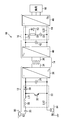
- FIG. 1 is a block diagram of a power conversion device according to the first embodiment.
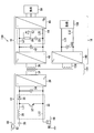
- FIG. 2 is a block diagram of the power converter according to the second embodiment.
- the power conversion device is configured for an electric vehicle, but the power conversion device according to the embodiment is not limited to this.
- FIG. 1 is a block diagram of a power conversion apparatus 10 according to the first embodiment.
- the power conversion device 10 according to the first embodiment is for an electric vehicle, for example.
- the power conversion device 10 is provided between a current collector 82 such as a panda graph supplied with DC power from a DC overhead line (DC feeder) 80 and a wheel 86 installed via a line 84. Is provided.
- a current collector 82 such as a panda graph supplied with DC power from a DC overhead line (DC feeder) 80
- DC feeder DC overhead line
- the power conversion apparatus 10 includes a primary circuit 12, a high-frequency transformer 14 that is an example of a transformer, and a secondary circuit 16.
- the primary circuit 12 is provided after the current collector 82 and the wheel 86 and before the high-frequency transformer 14.
- the primary circuit 12 converts AC power received from the current collector 82 and the wheel 86 into DC power and outputs the DC power to the high-frequency transformer 14.
- the primary circuit 12 includes an open contactor 20, a boost chopper 22 that is an example of a boost unit, a first filter capacitor 24 that is an example of a filter unit, and a high-frequency inverter 26.
- a wiring L11 one wiring (for example, positive-side wiring) from the open contactor 20 to the high-frequency inverter 26 is referred to as a wiring L11, and the other wiring (for example, negative-side wiring) is referred to as a wiring L12.
- the open contactor 20 is a contactor (or circuit breaker), and is connected in series to the wiring L11 at the rear stage of the current collector 82.
- the open contactor 20 switches between connection and disconnection of the path between the current collector 82 and the primary circuit 12, that is, on and off.
- the step-up chopper 22 is connected in series with the rear stage of the open contactor 20.
- the step-up chopper 22 is connected between the wiring L11 and the wiring L12.
- the boost chopper 22 boosts the voltage of the input DC power received through the current collector 82.
- the step-up chopper 22 removes a low-frequency ripple component.
- An example of the boost chopper 22 is a non-insulated boost choke converter.
- the step-up chopper 22 includes a reactor 28, a backflow prevention diode 30, and a switching element 32.
- the reactor 28 is connected in series with the wiring L11 at the rear stage of the open contactor 20.
- the backflow prevention diode 30 is connected in series to the wiring L11 subsequent to the reactor 28.
- the backflow prevention diode 30 is connected in a direction in which the current flow from the reactor 28 to the high frequency inverter 26 is in the forward direction. That is, the anode side of the backflow prevention diode 30 is connected to the reactor 28, and the cathode side is connected to the high frequency inverter 26.
- the switching element 32 is downstream of the reactor 28 and upstream of the backflow prevention diode 30, and is connected between the wiring L11 and the wiring L12.
- the switching element 32 receives a control signal corresponding to the switching frequency and the on-duty.
- the switching element 32 switches between on and off based on the control signal and performs a chopping operation.
- the boost chopper 22 boosts and outputs the input DC power.
- the first filter capacitor 24 is connected to the subsequent stage of the boost chopper 22.
- the first filter capacitor 24 is connected between the wiring L11 and the wiring L12.
- the first filter capacitor 24 removes the ripple component from the DC power boosted by the boost chopper 22 (ie, filters) and outputs the ripple component to the high frequency inverter 26.
- the first filter capacitor 24 may remove the ripple component in cooperation with the reactor 28.
- the high frequency inverter 26 is connected to the subsequent stage of the boost chopper 22 and the first filter capacitor 24.
- the high frequency inverter 26 is connected between the wiring L11 and the wiring L12.
- the high frequency inverter 26 converts the DC power from which the boosting and ripple components are removed into AC power and outputs the AC power to the high frequency transformer 14.
- the high frequency inverter 26 outputs AC power having a frequency that is n times (n is an integer of 2 or more) the commercial power source (50 Hz or 60 Hz).
- the high frequency transformer 14 is connected to the subsequent stage of the high frequency inverter 26 of the primary circuit 12.
- the high frequency transformer 14 has a primary winding 34 and a secondary winding 36.
- the primary winding 34 is connected to the high frequency inverter 26 of the primary circuit 12.
- the secondary winding 36 is connected to the secondary circuit 16.
- the high frequency transformer 14 transforms the voltage of the AC power output from the high frequency inverter 26 of the primary circuit 12 at a step-up ratio corresponding to the turn ratio of the primary winding 34 and the secondary winding 36 to the secondary circuit 16. Output.
- the primary winding 34 is electrically insulated from the secondary winding 36.
- the high frequency transformer 14 electrically insulates the primary circuit 12 connected to the primary winding 34 and the secondary circuit 16 connected to the secondary winding 36.
- the secondary circuit 16 is connected to the subsequent stage of the high-frequency transformer 14.
- the secondary circuit 16 converts AC power into DC power, then converts it into three-phase AC, and outputs it to the load 88.
- the secondary circuit 16 includes a rectifier 40, a second filter capacitor 42 that is an example of a first capacitor, a compensation unit 44, and a three-phase inverter 46 that is an example of a second inverter.
- one wiring (for example, positive-side wiring) from the rectifier 40 to the three-phase inverter 46 is referred to as a wiring L21, and the other wiring (for example, negative-side wiring) is referred to as a wiring L22.
- the rectifier 40 is connected to the subsequent stage of the high-frequency transformer 14.
- the rectifier 40 has a plurality of diodes, for example.
- the rectifier 40 converts the high-frequency AC power transformed by the high-frequency transformer 14 into DC power and outputs the DC power to the second filter capacitor 42.
- the second filter capacitor 42 is connected to the subsequent stage of the rectifier 40.
- the second filter capacitor 42 is connected between the wiring L21 and the wiring L22.
- the second filter capacitor 42 removes (that is, filters) a ripple component having a specific frequency (for example, 20 kHz or more) included in the DC power converted from AC power by the rectifier 40 and outputs the ripple component.
- the second filter capacitor 42 only needs to be able to remove the high-frequency ripple component, and its capacitance is smaller than the capacitance for removing the low-frequency ripple contained in the DC overhead wire 80.
- the compensation unit 44 is connected to the subsequent stage of the rectifier 40 and the second filter capacitor 42.
- the compensation unit 44 is connected between the wiring L21 and the wiring L22.
- the compensation unit 44 is connected to the second filter capacitor 42 in parallel.
- the compensation unit 44 includes a charging resistor 50 that is an example of a resistor, a discharge diode 52 that is an example of a diode, and a separation compensation capacitor 54 that is an example of a second capacitor.
- the charging resistor 50 is connected in series with the disconnection compensation capacitor 54.
- the charging resistor 50 and the separation compensation capacitor 54 are connected between the wiring L21 and the wiring L22. That is, the charging resistor 50 and the separation compensation capacitor 54 are connected in parallel with the second filter capacitor 42.
- the discharge diode 52 is connected in series with the separation compensation capacitor 54.
- the discharge diode 52 and the separation compensation capacitor 54 are connected between the wiring L21 and the wiring L22. That is, the discharge diode 52 and the separation compensation capacitor 54 are connected in parallel with the second filter capacitor 42.
- the discharge diode 52 is connected in parallel with the charging resistor 50.
- no resistor is provided between the rectifier 40 and the second filter capacitor 42.
- the resistance between the rectifier 40 and the second filter capacitor 42 is smaller than the resistance of the charging resistor 50. Even when a resistor is provided between the rectifier 40 and the second filter capacitor 42, the resistance of the resistor is preferably smaller than the resistance of the charging resistor 50.
- the charging resistor 50 charges the disconnection compensation capacitor 54 with a part of the DC power converted by the rectifier 40.
- the discharge diode 52 is connected in a direction in which the current flow from the wiring L22 to the wiring L21 is in the forward direction. That is, the anode side of the discharge diode 52 is connected to the separation compensation capacitor 54 and the wiring L22 side, and the cathode side is connected to the wiring L21.
- the discharge diode 52 discharges the electric power charged in the separation compensation capacitor 54.
- the disconnection compensation capacitor 54 is an electrolytic capacitor.
- the line-separation compensation capacitor 54 is charged with electric power by DC power converted from AC power by the rectifier 40.
- the disconnection compensation capacitor 54 continues the power supply with the charged power at the moment of power failure when the current collector 82 is separated from the DC overhead line 80 and the power supply is momentarily stopped.
- the electrostatic capacitance of the separation compensation capacitor 54 is larger than the electrostatic capacitance of the second filter capacitor 42.
- the electrostatic capacitance (for example, 10,000 ⁇ F) of the separation compensation capacitor 54 is 10 times or more the electrostatic capacitance (for example, 100 ⁇ F) of the second filter capacitor 42.
- the three-phase inverter 46 is connected to the second filter capacitor 42 and the subsequent stage of the compensation unit 44.
- the three-phase inverter 46 is connected between the wiring L21 and the wiring L22.
- the three-phase inverter 46 converts the DC power filtered by the second filter capacitor 42 into a three-phase AC having a frequency lower than the frequency of the AC power output from the high-frequency inverter 26 and having a high voltage (for example, 440 V).
- An example of the frequency of the three-phase AC output from the three-phase inverter 46 is the frequency of the commercial power supply.
- the three-phase inverter 46 outputs the converted three-phase alternating current to a load 88 such as an air conditioner and an electric air compressor.
- the DC overhead line 80 supplies DC power to the power converter 10.
- the boost chopper 22 boosts and outputs the voltage of the DC power supplied from the DC overhead line 80.
- the first filter capacitor 24 removes the ripple component from the boosted DC power and outputs it to the high frequency inverter 26.
- the high frequency inverter 26 converts DC power into high frequency AC power and outputs it to the high frequency transformer 14.
- the high-frequency transformer 14 outputs AC power transformed in voltage to the rectifier 40 by the primary winding 34 and the secondary winding 36 that are electrically insulated from each other.
- the rectifier 40 converts AC power into DC power and outputs it.
- the second filter capacitor 42 removes the ripple component of the DC power output from the rectifier 40 and outputs it.
- the three-phase inverter 46 converts the DC power, the ripple component of which has been filtered, into a three-phase AC and outputs it to the load 88.
- the disconnection compensation capacitor 54 of the compensation unit 44 is supplied from the rectifier 40 via the charging resistor 50. Charging with direct current power.
- the separation compensation capacitor 54 of the compensation unit 44 supplies the charged power to the three-phase via the discharge diode 52. Output to inverter 46.
- the power conversion device 10 can reduce the inrush charging current to the second filter capacitor 42 at the time of initial charging and reconnection after disconnection, so that the resistance connected in series with the second filter capacitor 42 is reduced. It can be omitted to simplify the configuration.
- the power converter 10 since the power converter 10 has the charging resistor 50 connected in series to the separation compensation capacitor 54 having a large capacitance, the inrush charging current to the separation compensation capacitor 54 can be suppressed. As a result, the power converter 10 can simplify the configuration by omitting the resistor and the contactor provided in the primary circuit 12 in order to suppress the inrush charging current to both the filter capacitor and the compensation capacitor.
- the power conversion device 10 since the charging resistor 50 is connected in series with the line-separation compensation capacitor 54, the second filter capacitor 42 almost absorbs the ripple component, and therefore the line-separation compensation capacitor 54 hardly receives the ripple component. For this reason, the power converter device 10 can extend the life by suppressing the degradation of the separation compensation capacitor 54. As a result, the power conversion device 10 can apply an electrolytic capacitor, which has a short life but can be reduced in size and weight, to the wire separation compensation capacitor 54. As a result, the power conversion device 10 can be reduced in size and weight.
- the capacitance of the first filter capacitor 24 can be reduced, for example, to about 100 ⁇ F. Furthermore, in the power conversion device 10, the capacitance of the first filter capacitor 24 can be further reduced by increasing the switching frequency of the switching element 32 of the boost chopper 22.
- the frequency of the AC power output from the high-frequency inverter 26 is high, for example, higher than the frequency of the commercial power supply.
- the power converter device 10 can reduce the electrostatic capacitance of the second filter capacitor 42 of the secondary circuit 16 to, for example, about 100 ⁇ F.
- the power converter device 10 can reduce the size and weight of the high-frequency transformer 14.
- FIG. 2 is a block diagram of the power conversion apparatus 110 according to the second embodiment.
- the power conversion device 110 according to the second embodiment includes a primary circuit 12, a high-frequency transformer 114, a secondary circuit 16, and a tertiary circuit 18.
- the high frequency transformer 114 further includes a tertiary winding 136.
- the tertiary winding 136 is connected to the tertiary circuit 18.
- the tertiary winding 136 is electrically insulated from the primary winding 34 and the secondary winding 36.
- the tertiary winding 136 receives AC power from the primary winding 34.
- the high frequency transformer 114 transforms the voltage of the AC power at a step-up ratio corresponding to the turn ratio of the primary winding 34 and the tertiary winding 136 and outputs the voltage to the tertiary circuit 18.
- the tertiary circuit 18 functions as a DC power source that outputs DC power.
- the tertiary circuit 18 includes a second rectifier 140 and a third filter capacitor 142 which is an example of a third capacitor.
- one wiring (for example, positive-side wiring) from the second rectifier 140 to the load 188 is referred to as a wiring L31, and the other wiring (for example, negative-side wiring) is referred to as a wiring L32.
- the second rectifier 140 is connected to the subsequent stage of the tertiary winding 136.
- the second rectifier 140 converts AC power received from the tertiary winding 136 into low voltage (for example, 100 V) DC power and outputs the DC power to the load 188.
- the third filter capacitor 142 is connected to the subsequent stage of the second rectifier 140.
- the third filter capacitor 142 is connected between the wiring L31 and the wiring L32.
- the third filter capacitor 142 removes a ripple component from the DC power output from the second rectifier 140.
- the secondary circuit 16 and the tertiary circuit 18 can be connected in parallel.
- a three-phase AC power source for example, 440 V
- a DC that supplies power to a control device that controls the electric vehicle. It has a power supply (for example, 100V).
- the direct current power supply is generally configured by providing a rectifier via a transformer at the subsequent stage of the three-phase alternating current power supply, and further includes a battery in order to continue power supply to the control device.
- a secondary circuit constituting a three-phase AC power supply is connected to the secondary winding of the high-frequency transformer, and a DC power supply is configured to the tertiary winding of the high-frequency transformer.
- the power conversion capacity of the secondary circuit 16 can be reduced as compared with the case where the DC power supply is configured by a circuit branched from the subsequent stage of the compensation unit 44 of the secondary circuit 16.
- the power converter 110 can reduce the electrostatic capacitance of the separation compensation capacitor 54 of the secondary circuit 16.
- the tertiary circuit 18 functions as a low-voltage DC power supply, no compensation unit is required. Thereby, even if the tertiary circuit 18 is added, the power converter 110 can suppress the complication and enlargement of a structure.
- the second filter capacitor 42 is an electrolytic capacitor.
- the second filter capacitor 42 may be an oil capacitor, a film capacitor, or the like.
Landscapes
- Engineering & Computer Science (AREA)
- Power Engineering (AREA)
- Transportation (AREA)
- Mechanical Engineering (AREA)
- Life Sciences & Earth Sciences (AREA)
- Sustainable Development (AREA)
- Sustainable Energy (AREA)
- Microelectronics & Electronic Packaging (AREA)
- Inverter Devices (AREA)
- Dc-Dc Converters (AREA)
Abstract
Description
図1は、第1実施形態にかかる電力変換装置10のブロック図である。第1実施形態にかかる電力変換装置10は、例えば、電気車用である。図1に示すように、電力変換装置10は、直流架線(直流き電線)80から直流電力が供給されるパンダグラフ等の集電器82と、線路84を介して設置された車輪86との間に設けられている。
図2は、第2実施形態にかかる電力変換装置110のブロック図である。図2に示すように、第2実施形態にかかる電力変換装置110は、一次回路12と、高周波変圧器114と、二次回路16と、三次回路18とを備える。
Claims (7)
- 直流電力を交流電力に変換して出力する一次回路と、
交流電力を直流電力に変換する二次回路と、
前記一次回路と前記二次回路とを電気的に絶縁して、前記一次回路が出力した前記交流電力の電圧を変圧して前記二次回路に出力する変圧器と、
を備え、
前記二次回路は、
前記交流電力から変換された前記直流電力のリプル成分を除去する第1コンデンサと、
前記第1コンデンサよりも静電容量が大きく、前記第1コンデンサと並列に接続され、前記交流電力から変換された前記直流電力によって電力を充電する第2コンデンサと、
前記第2コンデンサと直列に接続された抵抗器と、
前記第2コンデンサと直列に、かつ、前記抵抗器と並列に接続され、前記第2コンデンサに充電された電力を放電するダイオードと、
を有する電力変換装置。 - 前記第2コンデンサは、電解コンデンサである
請求項1に記載の電力変換装置。 - 前記第2コンデンサの静電容量は、前記第1コンデンサの静電容量の10倍以上である
請求項1または2に記載の電力変換装置。 - 前記一次回路は、
前記直流電力を昇圧する昇圧部と、
前記昇圧部が昇圧した前記直流電力からリプル成分を除去するフィルタ部と、
前記リプル成分を除去した前記直流電力を交流電力に変換して前記変圧器に出力するインバータと、
を有し、
前記二次回路は、
前記変圧器が変圧した前記交流電力を前記直流電力に変換して、前記第1コンデンサへと出力する整流器を有する
請求項1から3のいずれか1項に記載の電力変換装置。 - 前記整流器と前記第1コンデンサとの間の抵抗は、前記抵抗器の抵抗よりも小さい
請求項4に記載の電力変換装置。 - 前記二次回路は、
前記整流器が出力した直流電力を、前記インバータが出力する前記交流電力の周波数よりも低い周波数の交流電力に変換する第2インバータを更に有する
請求項4または5に記載の電力変換装置。 - 前記変圧器は、
前記一次回路と接続された一次巻線と、
前記二次回路と接続され、前記一次巻線から交流電力を受電する二次巻線と、
前記一次巻線及び前記二次巻線と電気的に絶縁され、前記一次巻線から交流電力を受電する三次巻線と、
を有し、
前記三次巻線が受電した前記交流電力を直流電力に変換して負荷に出力する第2整流器と、前記第2整流器が出力した前記直流電力からリプル成分を除去する第3コンデンサとを有する三次回路を
更に備える請求項1から6のいずれか1項に記載の電力変換装置。
Priority Applications (5)
| Application Number | Priority Date | Filing Date | Title |
|---|---|---|---|
| PCT/JP2016/056460 WO2017149702A1 (ja) | 2016-03-02 | 2016-03-02 | 電力変換装置 |
| CN201680057715.8A CN108141138A (zh) | 2016-03-02 | 2016-03-02 | 电力转换装置 |
| JP2018502942A JPWO2017149702A1 (ja) | 2016-03-02 | 2016-03-02 | 電力変換装置 |
| EP16892544.4A EP3425785A4 (en) | 2016-03-02 | 2016-03-02 | POWER CONVERSION DEVICE |
| US16/072,547 US20190036457A1 (en) | 2016-03-02 | 2016-03-02 | Power conversion device |
Applications Claiming Priority (1)
| Application Number | Priority Date | Filing Date | Title |
|---|---|---|---|
| PCT/JP2016/056460 WO2017149702A1 (ja) | 2016-03-02 | 2016-03-02 | 電力変換装置 |
Publications (1)
| Publication Number | Publication Date |
|---|---|
| WO2017149702A1 true WO2017149702A1 (ja) | 2017-09-08 |
Family
ID=59743631
Family Applications (1)
| Application Number | Title | Priority Date | Filing Date |
|---|---|---|---|
| PCT/JP2016/056460 Ceased WO2017149702A1 (ja) | 2016-03-02 | 2016-03-02 | 電力変換装置 |
Country Status (5)
| Country | Link |
|---|---|
| US (1) | US20190036457A1 (ja) |
| EP (1) | EP3425785A4 (ja) |
| JP (1) | JPWO2017149702A1 (ja) |
| CN (1) | CN108141138A (ja) |
| WO (1) | WO2017149702A1 (ja) |
Families Citing this family (3)
| Publication number | Priority date | Publication date | Assignee | Title |
|---|---|---|---|---|
| JP6736369B2 (ja) * | 2016-06-16 | 2020-08-05 | 東海旅客鉄道株式会社 | 電力変換システム |
| JP6736370B2 (ja) * | 2016-06-16 | 2020-08-05 | 東海旅客鉄道株式会社 | 電力変換システム |
| JP6818442B2 (ja) * | 2016-06-17 | 2021-01-20 | 東海旅客鉄道株式会社 | 電力変換システム |
Citations (6)
| Publication number | Priority date | Publication date | Assignee | Title |
|---|---|---|---|---|
| JPH0270201A (ja) * | 1988-09-03 | 1990-03-09 | Fuji Electric Co Ltd | 車輌用補助電源装置 |
| JPH1014134A (ja) * | 1996-06-20 | 1998-01-16 | Sony Corp | 安定化電源回路 |
| WO2006051843A1 (ja) * | 2004-11-12 | 2006-05-18 | Shinji Kudo | 電源装置 |
| JP2008154341A (ja) | 2006-12-15 | 2008-07-03 | Toshiba Corp | 電気車用電源装置 |
| JP2010041805A (ja) * | 2008-08-04 | 2010-02-18 | Toshiba Corp | 電気車用電源装置 |
| JP2015139264A (ja) * | 2014-01-21 | 2015-07-30 | 株式会社東芝 | 電力変換装置および電力変換装置の制御方法 |
Family Cites Families (8)
| Publication number | Priority date | Publication date | Assignee | Title |
|---|---|---|---|---|
| JPS6185067A (ja) * | 1984-10-01 | 1986-04-30 | Sharp Corp | 電源装置 |
| US6369558B2 (en) * | 2000-06-23 | 2002-04-09 | Rohm Co., Ltd. | Switching regulator |
| WO2006027744A2 (en) * | 2004-09-08 | 2006-03-16 | Eaton Corporation | Primary paralleled three-phase full-bridge dc-dc converter |
| US8644037B2 (en) * | 2008-07-15 | 2014-02-04 | General Electric Company | AC-AC converter with high frequency link |
| US20120275195A1 (en) * | 2011-04-28 | 2012-11-01 | Lorenzo Cividino | Low Noise, Highly Isolated Power Supply |
| US20130250637A1 (en) * | 2012-03-21 | 2013-09-26 | National Tsing Hua University | Single-Stage Single-Switch Voltage Converter |
| US9614456B2 (en) * | 2012-11-20 | 2017-04-04 | Mitsubishi Electric Corporation | Power conversion apparatus that prevents inrush current and air-conditioning apparatus using the same |
| JP6153491B2 (ja) * | 2014-03-28 | 2017-06-28 | オムロンオートモーティブエレクトロニクス株式会社 | 電力供給装置 |
-
2016
- 2016-03-02 US US16/072,547 patent/US20190036457A1/en not_active Abandoned
- 2016-03-02 EP EP16892544.4A patent/EP3425785A4/en not_active Withdrawn
- 2016-03-02 WO PCT/JP2016/056460 patent/WO2017149702A1/ja not_active Ceased
- 2016-03-02 JP JP2018502942A patent/JPWO2017149702A1/ja active Pending
- 2016-03-02 CN CN201680057715.8A patent/CN108141138A/zh active Pending
Patent Citations (6)
| Publication number | Priority date | Publication date | Assignee | Title |
|---|---|---|---|---|
| JPH0270201A (ja) * | 1988-09-03 | 1990-03-09 | Fuji Electric Co Ltd | 車輌用補助電源装置 |
| JPH1014134A (ja) * | 1996-06-20 | 1998-01-16 | Sony Corp | 安定化電源回路 |
| WO2006051843A1 (ja) * | 2004-11-12 | 2006-05-18 | Shinji Kudo | 電源装置 |
| JP2008154341A (ja) | 2006-12-15 | 2008-07-03 | Toshiba Corp | 電気車用電源装置 |
| JP2010041805A (ja) * | 2008-08-04 | 2010-02-18 | Toshiba Corp | 電気車用電源装置 |
| JP2015139264A (ja) * | 2014-01-21 | 2015-07-30 | 株式会社東芝 | 電力変換装置および電力変換装置の制御方法 |
Non-Patent Citations (1)
| Title |
|---|
| See also references of EP3425785A4 |
Also Published As
| Publication number | Publication date |
|---|---|
| EP3425785A4 (en) | 2019-10-30 |
| US20190036457A1 (en) | 2019-01-31 |
| JPWO2017149702A1 (ja) | 2018-06-14 |
| CN108141138A (zh) | 2018-06-08 |
| EP3425785A1 (en) | 2019-01-09 |
Similar Documents
| Publication | Publication Date | Title |
|---|---|---|
| CN108068650B (zh) | 通用电流充电器 | |
| CN110896245B (zh) | 车辆电源装置 | |
| US9758047B2 (en) | Dual voltage charging system with an integrated active filter auxiliary power module | |
| TWI536709B (zh) | 電源系統及供電方法 | |
| US9450412B2 (en) | Method and system for control power in remote DC power systems | |
| US9776518B2 (en) | System with battery charging device and vehicle electrical system power supply stage | |
| US9246399B2 (en) | Power supply system and control method thereof | |
| US9088221B2 (en) | High-voltage power supply module and power supply system | |
| US20120212986A1 (en) | Switching power supply apparatus | |
| US11472305B2 (en) | Charging circuit for a vehicle-side electrical energy store | |
| CN109687702B (zh) | Dc-dc转换器 | |
| CN110893823A (zh) | 车辆电源装置 | |
| JP2012205492A (ja) | 電力変換装置 | |
| KR102934950B1 (ko) | 충전 장치 | |
| WO2017149702A1 (ja) | 電力変換装置 | |
| US11760218B2 (en) | Charging circuit for a vehicle-side electrical energy store | |
| US20200220482A1 (en) | Power supply | |
| JP2016127680A (ja) | 電力変換装置 | |
| WO2011067974A1 (ja) | Pfcコンバータ | |
| US9627981B2 (en) | Bidirectional switched mode power supply | |
| MXPA04009241A (es) | Dispositivo para la transmision inductiva de la energia electrica. | |
| JP4751306B2 (ja) | 電気車用電源装置 | |
| JP6829068B2 (ja) | 鉄道車両用電力変換装置 | |
| HK1252510A1 (zh) | 带有缓冲器电路的电功率转换器 | |
| JP6314508B2 (ja) | 照明器具 |
Legal Events
| Date | Code | Title | Description |
|---|---|---|---|
| ENP | Entry into the national phase |
Ref document number: 2018502942 Country of ref document: JP Kind code of ref document: A |
|
| NENP | Non-entry into the national phase |
Ref country code: DE |
|
| WWE | Wipo information: entry into national phase |
Ref document number: 2016892544 Country of ref document: EP |
|
| ENP | Entry into the national phase |
Ref document number: 2016892544 Country of ref document: EP Effective date: 20181002 |
|
| 121 | Ep: the epo has been informed by wipo that ep was designated in this application |
Ref document number: 16892544 Country of ref document: EP Kind code of ref document: A1 |