WO2017149726A1 - Solénoïde - Google Patents
Solénoïde Download PDFInfo
- Publication number
- WO2017149726A1 WO2017149726A1 PCT/JP2016/056601 JP2016056601W WO2017149726A1 WO 2017149726 A1 WO2017149726 A1 WO 2017149726A1 JP 2016056601 W JP2016056601 W JP 2016056601W WO 2017149726 A1 WO2017149726 A1 WO 2017149726A1
- Authority
- WO
- WIPO (PCT)
- Prior art keywords
- coil
- permanent magnet
- solenoid
- magnetic flux
- case
- Prior art date
- Legal status (The legal status is an assumption and is not a legal conclusion. Google has not performed a legal analysis and makes no representation as to the accuracy of the status listed.)
- Ceased
Links
Images


Classifications
-
- H—ELECTRICITY
- H01—ELECTRIC ELEMENTS
- H01F—MAGNETS; INDUCTANCES; TRANSFORMERS; SELECTION OF MATERIALS FOR THEIR MAGNETIC PROPERTIES
- H01F7/00—Magnets
- H01F7/06—Electromagnets; Actuators including electromagnets
- H01F7/08—Electromagnets; Actuators including electromagnets with armatures
- H01F7/121—Guiding or setting position of armatures, e.g. retaining armatures in their end position
- H01F7/122—Guiding or setting position of armatures, e.g. retaining armatures in their end position by permanent magnets
-
- H—ELECTRICITY
- H01—ELECTRIC ELEMENTS
- H01F—MAGNETS; INDUCTANCES; TRANSFORMERS; SELECTION OF MATERIALS FOR THEIR MAGNETIC PROPERTIES
- H01F7/00—Magnets
- H01F7/06—Electromagnets; Actuators including electromagnets
- H01F7/08—Electromagnets; Actuators including electromagnets with armatures
- H01F7/081—Magnetic constructions
-
- H—ELECTRICITY
- H01—ELECTRIC ELEMENTS
- H01F—MAGNETS; INDUCTANCES; TRANSFORMERS; SELECTION OF MATERIALS FOR THEIR MAGNETIC PROPERTIES
- H01F7/00—Magnets
- H01F7/06—Electromagnets; Actuators including electromagnets
- H01F7/08—Electromagnets; Actuators including electromagnets with armatures
- H01F7/16—Rectilinearly-movable armatures
- H01F7/1607—Armatures entering the winding
- H01F7/1615—Armatures or stationary parts of magnetic circuit having permanent magnet
-
- H—ELECTRICITY
- H01—ELECTRIC ELEMENTS
- H01F—MAGNETS; INDUCTANCES; TRANSFORMERS; SELECTION OF MATERIALS FOR THEIR MAGNETIC PROPERTIES
- H01F7/00—Magnets
- H01F7/06—Electromagnets; Actuators including electromagnets
- H01F7/08—Electromagnets; Actuators including electromagnets with armatures
- H01F7/081—Magnetic constructions
- H01F2007/083—External yoke surrounding the coil bobbin, e.g. made of bent magnetic sheet
-
- H—ELECTRICITY
- H01—ELECTRIC ELEMENTS
- H01F—MAGNETS; INDUCTANCES; TRANSFORMERS; SELECTION OF MATERIALS FOR THEIR MAGNETIC PROPERTIES
- H01F7/00—Magnets
- H01F7/06—Electromagnets; Actuators including electromagnets
- H01F7/08—Electromagnets; Actuators including electromagnets with armatures
- H01F7/18—Circuit arrangements for obtaining desired operating characteristics, e.g. for slow operation, for sequential energisation of windings, for high-speed energisation of windings
- H01F2007/1894—Circuit arrangements for obtaining desired operating characteristics, e.g. for slow operation, for sequential energisation of windings, for high-speed energisation of windings minimizing impact energy on closure of magnetic circuit
-
- H—ELECTRICITY
- H01—ELECTRIC ELEMENTS
- H01F—MAGNETS; INDUCTANCES; TRANSFORMERS; SELECTION OF MATERIALS FOR THEIR MAGNETIC PROPERTIES
- H01F7/00—Magnets
- H01F7/02—Permanent magnets [PM]
Definitions
- the present invention relates to a solenoid that combines a permanent magnet and a coil.
- Patent Document 1 discloses a solenoid having a permanent magnet and a coil.
- the solenoid of this document has a structure in which a permanent magnet is disposed in a space surrounded by a movable core and a fixed core. Therefore, the magnetic field (magnetic path) generated by energizing the coil does not directly affect the permanent magnet. Also, it is described that the permanent magnet is not demagnetized even in the release operation of the solenoid, and the long life of the solenoid can be secured.
- the magnetic flux passing through the adsorbing portion disappears, and finally, the attraction of the movable iron core is almost nil.
- the magnetic flux generated when the coil is energized is sufficiently large relative to the magnetic flux from the permanent magnet, the magnetic flux passing through the adsorbing portion switches from the magnetic flux from the permanent magnet to the magnetic flux due to the coil energizing, There was a problem that began to occur. That is, there is a problem that the release operation of the solenoid becomes incomplete due to the amount of magnetic flux generated by the energization of the coil.
- An object of the present invention is to provide a solenoid capable of reliably performing a release operation by reducing the suction force of an iron core.
- a ring member is disposed in close contact with the permanent magnet and A movable core was inserted, and a metal coil cover was installed between the movable core and the coil so as to cover the entire coil.
- the distance between the inner wall of the case and the ring member may be in the range of 0.1 mm to 0.3 mm.
- the coil in the type of solenoid combining a permanent magnet and a coil, the coil is disposed in a case so as to cover the entire coil with a metal coil cover.
- a magnetic path through which the magnetic flux generated from the permanent magnet passes and a magnetic path through which the magnetic flux generated by energization of the coil passes are generated independently of each other.
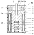
- FIG. 1A It is a longitudinal cross-sectional view (at the time of non-energization) of the solenoid 10 which is an example of embodiment of this invention. It is an enlarged view in the A section of FIG. 1A. It is operation
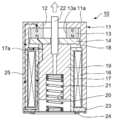
- FIG. 1A is a longitudinal sectional view of a solenoid 10 according to the present invention
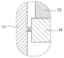
- FIG. 1B is an enlarged view of a portion A shown in FIG. 1A.
- the solenoid 10 according to the present invention is of a type in which a permanent magnet 13 and a coil 16 are disposed in a cylindrical case 11 as shown in FIG. 1A.
- a circular opening 12 is formed on the end face 11 a (upper side in FIG. 1A) of the case 11.
- a cylindrical permanent magnet 13 having a hole 13 a is provided in the case 11 so as to be in close contact with the back side (inner side) of the end face 11 a of the case 11.
- the hole 13a of the permanent magnet 13 and the opening 12 of the case 11 are in a positional relationship such that they are concentric with each other as shown in FIG. 1A.
- a gap may be provided between the permanent magnet 13 and the inner wall surface of the case 11 as shown in FIG. 1A, and a nonmagnetic substance such as a resin may be loaded in the gap.
- a nonmagnetic substance such as a resin
- a ring member 14 is disposed in close contact with the lower surface (lower side in FIG. 1A) of the permanent magnet 13 built in the case 11.
- the inner diameter side of the ring member 14 is arranged to be concentric with the hole 13a of the permanent magnet 13 as shown in FIG. 1A.
- the outer diameter side of the ring member 14 is installed in the case 11 in a state where a constant distance d is maintained from the inner side (inner wall) of the case 11.
- the distance d is in the range of 0.1 mm to 0.3 mm in view of the magnetic path described later.
- a movable iron core (plunger) 19 is inserted into a cylindrical coil (electromagnetic coil) 16 built in the case 11, and an axial direction is generated by the electromagnetic force generated when the coil 16 is energized. It can move in the vertical direction of FIG. 1A) (see FIGS. 1A and 2). Further, a recess 20 is provided in the axial direction on one end side (lower side in FIG. 1A) of the movable iron core 19, and a spring 21 is mounted in the recess 20. One end side (upper side in FIG. 1A) of the spring 21 is fitted in the recess 20, and the other end side (lower side in FIG. 1A) is fitted and fixed in the convex portion formed on the lid 24 of the solenoid 10. ing.
- a shaft 22 is provided on the other end side (upper side in FIG. 1A) of the movable iron core 19, that is, on the side opposite to the recess 20.
- the shaft 22 penetrates the opening 12 of the case 11, the hole 13a of the permanent magnet 13 and the inner diameter side of the ring member 14 in conjunction with it. Can move to
- a metal coil cover 17 is disposed between the coil 16 and the movable iron core 19 so as to cover the entire coil 16.
- the coil cover 17 has a weir 17a on one end side, and the coil cover 17 fits in the inner wall surface of the case 11 while covering the one end side (upper side in FIG. 1A) of the coil 16 It is fixed to case 11. Further, a gap 18 of a fixed distance is formed in the axial direction of the solenoid 10 with respect to the lower surface (lower side in FIG. 1A) of the ring member 14 on the upper surface (upper side in FIG. 1A) of the ridge 17a.
- the other end side (lower side in FIG. 1A) of the coil 16 is fixed by caulking the lid 24 and the case 11 via the ring member 23.
- the space 18 may be filled with a nonmagnetic substance such as a resin.
- the solenoid 10 according to the embodiment of the present invention is basically configured as described above. Next, the operation and the effect will be described using the drawings.
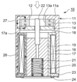
- the coil 16 in the solenoid 10 shown in FIG. 1A is not energized, the arrangement of each component of the solenoid 10 such as the movable iron core 19 and the shaft 22 is as shown in FIG.
- the movable iron core 19 is attracted to the permanent magnet 13 side (upper side in FIG. 3) by the elastic force of the spring 21 mounted in the recess 20 and the magnetic force of the permanent magnet 13 and comes into contact with the ring member 14.
- the N pole of the permanent magnet 13 is the ring member 14 side (the lower side in FIG. 3) and the S pole is the opening 12 side of the case 11 (the upper side in FIG.
- the flow of magnetic flux is formed like the first magnetic path 25 shown in FIG.
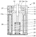
- the magnetic path generated in the solenoid 10 is as shown in FIG. That is, as shown in FIG. 4, when the coil 16 is energized (when the coil 16 is excited to become a magnetic flux in the opposite direction to the magnetic flux of the permanent magnet 13), the first magnetic path 25 shown in FIG. The magnetic flux of the coil 16 flows in the second magnetic path 26.
- the second magnetic path 26 is located in the middle of the first magnetic path 25. Therefore, when the magnetic flux of the coil 16 circulates in the second magnetic path 26 by the excitation of the coil 16, the first magnetic path 25 is magnetically saturated. Magnetic resistance increases.
- the magnetic flux of the permanent magnet 13 passes from the first magnetic path 25 having high magnetic resistance to the third magnetic path 27 via the distance d between the outer diameter side of the ring member 14 and the inner side (inner wall) of the case 11 start.
- the magnetic flux passing through the portion where the ring member 14 and the movable core 19 are attracted to each other is reduced.
- the movable core 19 and the ring member 14 are separated from each other, and the movable core 19 can be moved to the lower position by a slight external force (the direction of the arrow in FIG. 5).
- the effect of the present invention is obtained when the direction of the magnetic flux generated by the permanent magnet and the direction of the magnetic flux generated by energizing the coil face each other. It is expressed. Further, as shown in FIG. 6, the direction of the magnetic flux generated by the permanent magnet and the direction of the magnetic flux generated by energization of the coil are opposite to the direction of the magnetic flux shown in FIGS. Also the same effect as the present invention is expressed.
Landscapes
- Physics & Mathematics (AREA)
- Electromagnetism (AREA)
- Engineering & Computer Science (AREA)
- Power Engineering (AREA)
- Electromagnets (AREA)
Abstract
Priority Applications (5)
| Application Number | Priority Date | Filing Date | Title |
|---|---|---|---|
| JP2018502452A JPWO2017149726A1 (ja) | 2016-03-03 | 2016-03-03 | ソレノイド |
| CN201680083131.8A CN108780689B (zh) | 2016-03-03 | 2016-03-03 | 螺线管 |
| PCT/JP2016/056601 WO2017149726A1 (fr) | 2016-03-03 | 2016-03-03 | Solénoïde |
| US16/081,681 US11049635B2 (en) | 2016-03-03 | 2016-03-03 | Solenoid |
| EP16892566.7A EP3425648B1 (fr) | 2016-03-03 | 2016-03-03 | Solénoïde |
Applications Claiming Priority (1)
| Application Number | Priority Date | Filing Date | Title |
|---|---|---|---|
| PCT/JP2016/056601 WO2017149726A1 (fr) | 2016-03-03 | 2016-03-03 | Solénoïde |
Publications (1)
| Publication Number | Publication Date |
|---|---|
| WO2017149726A1 true WO2017149726A1 (fr) | 2017-09-08 |
Family
ID=59743642
Family Applications (1)
| Application Number | Title | Priority Date | Filing Date |
|---|---|---|---|
| PCT/JP2016/056601 Ceased WO2017149726A1 (fr) | 2016-03-03 | 2016-03-03 | Solénoïde |
Country Status (5)
| Country | Link |
|---|---|
| US (1) | US11049635B2 (fr) |
| EP (1) | EP3425648B1 (fr) |
| JP (1) | JPWO2017149726A1 (fr) |
| CN (1) | CN108780689B (fr) |
| WO (1) | WO2017149726A1 (fr) |
Cited By (3)
| Publication number | Priority date | Publication date | Assignee | Title |
|---|---|---|---|---|
| JP2019207914A (ja) * | 2018-05-28 | 2019-12-05 | 株式会社不二越 | 永久磁石内蔵型ソレノイド |
| KR20240068691A (ko) * | 2021-11-09 | 2024-05-17 | 미쓰비시덴키 가부시키가이샤 | 솔레노이드 및 개폐기 |
| WO2026053747A1 (fr) * | 2024-09-04 | 2026-03-12 | 株式会社デンソー | Dispositif à électroaimant, système à électroaimant et relais électromagnétique |
Families Citing this family (3)
| Publication number | Priority date | Publication date | Assignee | Title |
|---|---|---|---|---|
| KR102203414B1 (ko) * | 2019-01-02 | 2021-01-15 | 효성중공업 주식회사 | 액츄에이터 |
| CN109813761B (zh) * | 2019-03-12 | 2022-02-08 | 大连海事大学 | 一种电感磁塞式油液在线监测装置 |
| EP4067692A4 (fr) * | 2019-11-27 | 2023-08-09 | Kabushiki Kaisha Toshiba | Dispositif de support et unité de support |
Citations (4)
| Publication number | Priority date | Publication date | Assignee | Title |
|---|---|---|---|---|
| US4419643A (en) * | 1981-04-22 | 1983-12-06 | Hosiden Electronics Co., Ltd. | Self-sustaining solenoid |
| JPS59501928A (ja) * | 1982-10-21 | 1984-11-15 | アルストム−アトランテイツク | 高感度ストライカ |
| JPS646573A (en) * | 1987-06-30 | 1989-01-11 | Yazaki Corp | Manufacture of monostable type latching solenoid |
| JP2002289430A (ja) * | 2001-01-18 | 2002-10-04 | Hitachi Ltd | 電磁石およびそれを用いた開閉装置の操作機構 |
Family Cites Families (11)
| Publication number | Priority date | Publication date | Assignee | Title |
|---|---|---|---|---|
| US3814376A (en) * | 1972-08-09 | 1974-06-04 | Parker Hannifin Corp | Solenoid operated valve with magnetic latch |
| US4127835A (en) * | 1977-07-06 | 1978-11-28 | Dynex/Rivett Inc. | Electromechanical force motor |
| US4660010A (en) * | 1985-10-15 | 1987-04-21 | Ledex, Inc. | Rotary latching solenoid |
| US5190223A (en) * | 1988-10-10 | 1993-03-02 | Siemens Automotive L.P. | Electromagnetic fuel injector with cartridge embodiment |
| JP3618503B2 (ja) * | 1997-01-31 | 2005-02-09 | 住友電装株式会社 | ソレノイド装置 |
| CN1234135C (zh) * | 2001-01-18 | 2005-12-28 | 株式会社日立制作所 | 电磁铁和使用该电磁铁的开关装置的操作机构 |
| WO2008075640A1 (fr) | 2006-12-18 | 2008-06-26 | Fuji Electric Systems Co., Ltd. | Dispositif électromagnétique |
| US8581682B2 (en) * | 2009-10-07 | 2013-11-12 | Tyco Electronics Corporation | Magnet aided solenoid for an electrical switch |
| CN102779611B (zh) * | 2012-07-12 | 2014-04-09 | 浙江科技学院 | 永磁回复型高速开关电磁铁 |
| EP3220027B1 (fr) * | 2014-11-13 | 2019-07-17 | Eagle Industry Co., Ltd. | Dispositif d'électrovanne |
| US10655748B2 (en) * | 2018-07-13 | 2020-05-19 | Bendix Commercial Vehicle Systems Llc | Magnetic latching solenoid valve |
-
2016
- 2016-03-03 US US16/081,681 patent/US11049635B2/en active Active
- 2016-03-03 JP JP2018502452A patent/JPWO2017149726A1/ja active Pending
- 2016-03-03 WO PCT/JP2016/056601 patent/WO2017149726A1/fr not_active Ceased
- 2016-03-03 EP EP16892566.7A patent/EP3425648B1/fr active Active
- 2016-03-03 CN CN201680083131.8A patent/CN108780689B/zh active Active
Patent Citations (4)
| Publication number | Priority date | Publication date | Assignee | Title |
|---|---|---|---|---|
| US4419643A (en) * | 1981-04-22 | 1983-12-06 | Hosiden Electronics Co., Ltd. | Self-sustaining solenoid |
| JPS59501928A (ja) * | 1982-10-21 | 1984-11-15 | アルストム−アトランテイツク | 高感度ストライカ |
| JPS646573A (en) * | 1987-06-30 | 1989-01-11 | Yazaki Corp | Manufacture of monostable type latching solenoid |
| JP2002289430A (ja) * | 2001-01-18 | 2002-10-04 | Hitachi Ltd | 電磁石およびそれを用いた開閉装置の操作機構 |
Cited By (5)
| Publication number | Priority date | Publication date | Assignee | Title |
|---|---|---|---|---|
| JP2019207914A (ja) * | 2018-05-28 | 2019-12-05 | 株式会社不二越 | 永久磁石内蔵型ソレノイド |
| JP7161095B2 (ja) | 2018-05-28 | 2022-10-26 | 株式会社不二越 | 永久磁石内蔵型ソレノイド |
| KR20240068691A (ko) * | 2021-11-09 | 2024-05-17 | 미쓰비시덴키 가부시키가이샤 | 솔레노이드 및 개폐기 |
| KR102825104B1 (ko) | 2021-11-09 | 2025-06-25 | 미쓰비시덴키 가부시키가이샤 | 솔레노이드 및 개폐기 |
| WO2026053747A1 (fr) * | 2024-09-04 | 2026-03-12 | 株式会社デンソー | Dispositif à électroaimant, système à électroaimant et relais électromagnétique |
Also Published As
| Publication number | Publication date |
|---|---|
| EP3425648A4 (fr) | 2019-08-07 |
| US11049635B2 (en) | 2021-06-29 |
| CN108780689B (zh) | 2021-06-08 |
| US20190122797A1 (en) | 2019-04-25 |
| JPWO2017149726A1 (ja) | 2018-12-27 |
| EP3425648B1 (fr) | 2020-07-29 |
| EP3425648A1 (fr) | 2019-01-09 |
| CN108780689A (zh) | 2018-11-09 |
Similar Documents
| Publication | Publication Date | Title |
|---|---|---|
| WO2017149726A1 (fr) | Solénoïde | |
| JP4734766B2 (ja) | 磁石可動型電磁アクチュエータ | |
| JP2006108615A (ja) | 電磁アクチュエータ | |
| JP6484911B2 (ja) | 永久磁石内蔵型ソレノイド | |
| JP6731630B2 (ja) | 電磁継電器 | |
| JP4513890B2 (ja) | 電磁弁 | |
| JP2016009793A (ja) | リニアソレノイド | |
| WO2013153817A1 (fr) | Contacteur électromagnétique | |
| JP2015028979A (ja) | 電磁石装置 | |
| JP5494681B2 (ja) | 電磁弁 | |
| JP2015094415A (ja) | 電磁弁 | |
| JP6469325B1 (ja) | 電磁アクチュエータおよび油圧調整機構 | |
| JP5124048B2 (ja) | 釈放形電磁石装置 | |
| JP2015121289A (ja) | 電磁弁装置 | |
| WO2011125142A1 (fr) | Électroaimant polaire et contact électromagnétique | |
| JP6554492B2 (ja) | ソレノイド | |
| JP7161095B2 (ja) | 永久磁石内蔵型ソレノイド | |
| CN119108235A (zh) | 电磁接触器 | |
| JP5627475B2 (ja) | 開閉器の操作機構 | |
| JP5505211B2 (ja) | 有極電磁石及び電磁接触器 | |
| WO2018030053A1 (fr) | Actionneur à solénoïde | |
| JP4874703B2 (ja) | 電磁アクチュエータ | |
| JP6736330B2 (ja) | 電磁弁用カートリッジアッシ、電磁弁用ソレノイドおよび電磁弁 | |
| JP2006313694A (ja) | 電磁アクチュエータ及び開閉器 | |
| JP2008306123A (ja) | 電磁アクチュエータ |
Legal Events
| Date | Code | Title | Description |
|---|---|---|---|
| WWE | Wipo information: entry into national phase |
Ref document number: 2018502452 Country of ref document: JP |
|
| NENP | Non-entry into the national phase |
Ref country code: DE |
|
| WWE | Wipo information: entry into national phase |
Ref document number: 2016892566 Country of ref document: EP |
|
| ENP | Entry into the national phase |
Ref document number: 2016892566 Country of ref document: EP Effective date: 20181004 |
|
| 121 | Ep: the epo has been informed by wipo that ep was designated in this application |
Ref document number: 16892566 Country of ref document: EP Kind code of ref document: A1 |