WO2017149763A1 - Unité de charge/décharge - Google Patents
Unité de charge/décharge Download PDFInfo
- Publication number
- WO2017149763A1 WO2017149763A1 PCT/JP2016/056813 JP2016056813W WO2017149763A1 WO 2017149763 A1 WO2017149763 A1 WO 2017149763A1 JP 2016056813 W JP2016056813 W JP 2016056813W WO 2017149763 A1 WO2017149763 A1 WO 2017149763A1
- Authority
- WO
- WIPO (PCT)
- Prior art keywords
- power
- charger
- discharger
- charge
- fuse
- Prior art date
- Legal status (The legal status is an assumption and is not a legal conclusion. Google has not performed a legal analysis and makes no representation as to the accuracy of the status listed.)
- Ceased
Links
Images






Classifications
-
- H—ELECTRICITY
- H02—GENERATION; CONVERSION OR DISTRIBUTION OF ELECTRIC POWER
- H02J—ELECTRIC POWER NETWORKS; CIRCUIT ARRANGEMENTS OR SYSTEMS FOR SUPPLYING OR DISTRIBUTING ELECTRIC POWER; SYSTEMS FOR STORING ELECTRIC ENERGY
- H02J7/00—Circuit arrangements for charging or discharging batteries or for supplying loads from batteries
Definitions
- This invention relates to the charger / discharger which charges the storage battery with which the inside of the vehicle was equipped, or discharges the electric power charged by the storage battery.
- an electric power supply system that supplies electric power to a load in a house from a storage battery provided in a vehicle such as an electric vehicle or charges a storage battery from a commercial system for home use.
- the power supply system converts DC power from the storage battery provided inside the vehicle into an AC power conditioner that is a charger / discharger. Converted into electric power to supply AC power to the load in the house.
- the power supply system converts AC power from the home-use commercial system into DC power using an electric vehicle power conditioner, which is a charger / discharger. DC power is supplied to the storage battery provided.
- a cable serving as a power path is used.
- Patent Document 1 describes a mechanism for protecting a cable serving as a power path.
- the cable is protected by a fuse, and the current provided to the cable serving as a power path and the output time are limited to protect the fuse provided in the cable.
- the cable of Patent Document 1 is adopted in such a power supply system, the cable becomes thick and heavy, and it becomes difficult for the user to handle it on a daily basis.
- a thin and light cable is employed in such a power supply system so that a user can handle it on a daily basis, there is a possibility that the fuse provided in the cable is not sufficiently protected.
- the present invention has been made in view of the above, and an object thereof is to obtain a charger / discharger that can easily handle a cable while protecting a fuse provided in the cable.
- the charger / discharger of the present invention uses external power to charge a storage battery provided inside the vehicle, or uses the power charged in the storage battery as an external load. It is a charger / discharger to be discharged, and includes a charger / discharger body, a charge / discharge cable, a charge / discharge connector, and an insulating member.
- the charger / discharger body includes a power converter that converts the supplied power in accordance with the supply destination.
- the charge / discharge cable includes an electric wire extending from the inside of the charger / discharger body and serving as a path of supplied power or power supplied to a supply destination.
- the charge / discharge connector includes a first electric wire extending from the inside of the charge / discharge cable, a fuse connected to one end of the first electric wire, and a second electric wire connected to the opposite side of the first electric wire of the fuse.
- the charging / discharging cable is provided on the opposite side of the charger / discharger body, and is electrically connected to the vehicle by being connected to the vehicle inlet.
- the insulating member has electrical insulation and heat dissipation, and contacts the fuse and covers the fuse.
- FIG. 1 The block diagram which shows the structural example of the electric power supply system containing the charger / discharger which concerns on Embodiment 1.
- FIG. The block diagram which shows the structural example of the periphery of the subscriber
- FIG. The perspective view which shows the external appearance of the charger / discharger which concerns on Embodiment 1.
- FIG. The block diagram which shows the detail of each electric circuit system
- the figure which shows an example of a structure of the interface of the form with which the charger / discharger which concerns on Embodiment 1 and the electric vehicle were connected.
- FIG. 1 Sectional drawing which shows an example of a structure of the charging / discharging cable and charging / discharging connector in the charger / discharger which concerns on Embodiment 1.
- FIG. 1 The figure which shows an example of the structure at the time of the fuse used for the charger / discharger concerning Embodiment 1 being coat
- Sectional drawing which shows an example of the structure of the charging / discharging cable and charging / discharging connector in the charger / discharger which concerns on Embodiment 2.
- FIG. 1 is a block diagram illustrating a configuration example of a power supply system 1 including a charger / discharger 10 according to the first embodiment.
- FIG. 2 is a block diagram showing a configuration example around the home controller 38 connected to the charger / discharger 10 according to the first embodiment.
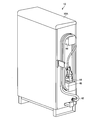
- FIG. 3 is a perspective view showing an appearance of the charger / discharger 10 according to the first embodiment.
- FIG. 4 is a block diagram illustrating details of an electric circuit system in each of the power converter 30, the charge / discharge cable 42, the charge / discharge connector 44, and the electric vehicle 12 of the charger / discharger 10 according to the first embodiment. is there.
- the power supply system 1 includes a charger / discharger 10, an electric vehicle 12, a commercial system 14, a main earth leakage circuit breaker 16, a maintenance MCCB (Molded Case Circuit Breaker) 18, and a solar battery. 20, a solar battery power conditioner 22, a switching switch 24, a switching switch 26, a residential distribution board 28, a voltage detection transformer VT, and a current transformer CT.
- the charger / discharger 10 is an electric vehicle power conditioner, that is, an EV-PCS (Electric Vehicle Power Conditioning Sub-system), and is indicated as EV-PCS in FIG.
- the electric vehicle 12 is an EV (Electric Vehicle) and is shown as EV in FIG.
- the solar cell power conditioner 22 is a PV-PCS (Photo Voltaic Power Conditioning Sub-system), and is indicated as PV-PCS in FIG.
- the charger / discharger 10 is electrically connected to the commercial system 14 that is the power source of the power system of the power company and the solar cell 20 that is a natural energy power generation system.
- the charger / discharger 10 supplies the electric power supplied from the commercial system 14 and the electric power supplied from the solar battery 20 to the main battery 80 shown in FIG. 4 of the electric vehicle 12 as a vehicle for charging.
- the charger / discharger 10 is not limited to this, and is connected to at least one of the power source of the power system and the natural energy power generation system, and is supplied from the power source of the power system and the natural energy power generation system. What is necessary is just to charge the storage battery of a vehicle using at least one among the electric power to be.
- a charger / discharger main body 10 ⁇ / b> A that is a main body of the charger / discharger 10 includes a power converter 30, a current transformer 32, and disconnection electromagnetic contactors 34, 36.
- the current transformer 32 detects a reverse power flow from the charger / discharger 10 to the commercial system 14.
- the disconnecting electromagnetic contactors 34 and 36 are open / close switches that switch between open and closed based on control from the control unit 58 of the power converter 30 shown in FIG. 4.
- the disconnecting electromagnetic contactors 34 and 36 can be disconnected from the electric circuit system of the commercial system 14 by opening the circuit when the supply of power from the commercial system 14 is stopped due to a power failure or the like. .
- the side where the current transformer 32 and the disconnecting electromagnetic contactors 34 and 36 are provided that is, the side to which the commercial system 14, the solar cell 20, and the residential distribution board 28 are connected is described below. Is referred to as the A side of the power converter 30.
- the side to which the electric vehicle 12 is connected is hereinafter referred to as the B side of the power converter 30.
- the charger / discharger 10 is electrically connected to a home controller 38 as shown in FIG.
- the home controller 38 is electrically connected to a HEMS (Home Energy Management System) controller 40.
- the home controller 38 displays the state of the charger / discharger 10 and accepts an operation input from the user.
- the HEMS controller 40 is a charger / discharger according to the power consumption state of the load in the house connected to the residential distribution board 28 and the power generation state of the solar battery 20 connected to the solar battery power conditioner 22. 10 and the operation state of the load in the house connected to the distribution board 28 for house.
- the charger / discharger 10 is provided at the charger / discharger main body 10 ⁇ / b> A including the power converter 30, the charge / discharge cable 42 extending from the power converter 30, and the tip of the charge / discharge cable 42.
- the charging / discharging connector 44 and storage holders 46 and 48 for storing the charging / discharging cable 42 in a wound manner are provided.
- the charge / discharge cable 42 and the charge / discharge connector 44 are electrically connected to the B side of the power converter 30.
- the charger / discharger 10 is electrically connected to the electric vehicle 12 by connecting the charging / discharging connector 44 to the inlet 76 (see FIG. 4) of the electric vehicle 12. Details of the structures of the charge / discharge cable 42 and the charge / discharge connector 44 will be described later.
- the power converter 30 includes a current transformer 32 and disconnecting electromagnetic contactors 34 and 36, a maintenance MCCB 18, a current transformer CT, a voltage detection transformer VT, and a main earth leakage circuit breaker 16. It is electrically connected to the commercial system 14 via The power converter 30 is electrically connected to the solar cell 20 through the current transformer 32, the switching switch 24, and the solar cell power conditioner 22. The power converter 30 is electrically connected to the residential distribution board 28 via the switching switch 26. The power converter 30 converts the AC power supplied from the commercial system 14 and the AC power supplied from the solar battery 20 via the solar battery power conditioner 22 into DC power and supplies the DC power to the electric vehicle 12. .
- the electric vehicle 12 includes various storage batteries including a main battery 80 (see FIG. 4). At least the main battery 80 stores DC power supplied after being converted into DC current by the charger / discharger 10.
- the storage battery including the main battery 80 of the electric vehicle 12 is exemplified as having a power capacity in the range of 1 kWh to 30 kWh, but the first embodiment is not limited to this range.
- the storage battery including the main battery 80 of the electric vehicle 12 is exemplified by a commonly used lithium ion battery (LiB) in the first embodiment.
- LiB lithium ion battery
- the charger / discharger 10 is electrically connected to the electric vehicle 12, but the present invention is not limited to this.
- the charger / discharger 10 may be electrically connected to a plug-in hybrid vehicle (PHEV (Plug-in Hybrid Electric Vehicle)) that supports charging / discharging instead of the electric vehicle 12.
- PHEV Plug-in Hybrid Electric Vehicle
- the commercial system 14 is a power source of the power system of the power company, and is a supply source capable of supplying AC power to the charger / discharger 10 and the residential distribution board 28.
- the commercial system 14 is exemplified by a case where the electric power is in the range of 3 kW to 12 kW at a single-phase 200 V, but the first embodiment is not limited to this range.
- the commercial system 14 is electrically connected to the residential distribution board 28 via the main earth leakage circuit breaker 16, the voltage detection transformer VT, the current transformer CT, and the switching switch 26.
- the main earth leakage circuit breaker 16 is a circuit breaker provided to allow the commercial system 14 to receive power in the house.
- the voltage detection transformer VT and the current transformer CT are installed in this order near the main circuit leakage breaker 16 on the opposite side of the commercial system 14.
- the voltage detection transformer VT outputs a voltage signal V having a voltage proportional to the voltage at the installed location to the control unit 58 (see FIG. 4) of the power converter 30.
- the current transformer CT outputs a current signal I of a current proportional to the voltage at the installed location to the control unit 58 (see FIG. 4) of the power converter 30.
- the maintenance MCCB 18 is an on / off switch provided on the charger / discharger 10 side where the output from the main earth leakage breaker 16 is branched to the charger / discharger 10 side and the residential distribution board 28 side.
- the maintenance MCCB 18 is closed when the charging / discharging device 10 and the commercial system 14 are connected to each other.
- the maintenance MCCB 18 is opened when charging / discharging is stopped and maintenance / repair is performed due to a failure or the like.
- the connection between the electric appliance 10 and the commercial system 14 is opened.
- the solar cell 20 is an example of a natural energy power generation system that generates power using sunlight.
- a solar cell is used as a natural energy power generation system, but the present invention is not limited to this, and a hydroelectric generator such as a water turbine or a wind power generator may be used.
- the solar cell power conditioner 22 is a photovoltaic power conversion device, which converts a direct current generated by the solar cell 20 into an alternating current and outputs the alternating current.
- the solar cell 20 is exemplified by the case where the amount of power generation varies depending on the installation area and the amount of solar radiation, and the amount of power generation is in the range of 2 kW to 12 kW, but Embodiment 1 is not limited to this.
- the switching switch 24 can switch the connection destination where the solar cell 20 is electrically connected via the solar cell power conditioner 22 between the charger / discharger 10 and the residential distribution board 28.
- the switching switch 26 can switch the connection destination to which the residential distribution board 28 is electrically connected between the charger / discharger 10 and the commercial system 14 via the main leakage breaker 16.
- the residential distribution board 28 includes a main earth leakage breaker in the distribution board and a plurality of branch breakers. Each branch breaker is connected to a residential load that uses AC power.
- the residential distribution board 28 has a total load capacity of a general household to be connected within a range of, for example, 3 kW to 12 kW. In FIG. 1, the residential distribution board 28 includes four branch breakers, but is not limited thereto. The number of breakers provided in the residential distribution board 28 may be 1 to 3, or 5 or more.
- the residential distribution board 28 is electrically connected to the switching switch 26.
- the residential distribution board 28 is electrically connected to the solar battery 20 via the switching switch 24 and the solar battery power conditioner 22.
- the power supply system 1 including the charger / discharger 10 according to the first embodiment, when the commercial system 14 is blacked out due to a disaster or the like, the power generation amount of the solar cell 20 is abruptly accompanied with a rapid change in the amount of solar radiation.
- the power supply system 1 charges the storage battery of the electric vehicle 12 with power from the commercial system 14 or the solar battery 20 and supplies the power charged in the storage battery of the electric vehicle 12 to the residential distribution board 28. And can be switched. Furthermore, the power supply system 1 can switch between charging the storage battery of the electric vehicle 12 with power from the commercial system 14 and charging the storage battery of the electric vehicle 12 with power from the solar battery 20.
- the power supply system 1 can confirm the state of the charger / discharger 10 with the home controller 38.
- the HEMS controller 40 of the power supply system 1 depends on the power consumption state of the load in the house connected to the distribution board 28 for house and the power generation state of the solar battery 20 connected to the power conditioner 22 for solar battery. Then, the operation state of the load in the house connected to the charger / discharger 10 and the distribution board 28 for house is controlled.
- the charging / discharging connector 44 of the charger / discharger 10 is fitted into or removed from the inlet 76 shown in FIG. 4 of the electric vehicle 12, the power supply system 1 is electrically connected to the electric vehicle 12. Or can be cut.
- FIG. 4 shows a state where the charger / discharger 10 and the electric vehicle 12 are electrically connected.
- the power converter 30 of the charger / discharger 10 includes a contactor 50, reactors 52X and 52Y, AC / DC exchangers 54A, 54B, and 54C, drive units 56A, 56B, and 56C, and a control unit 58.
- a power supply unit 60 a battery 62, capacitors 64 and 66, an insulating transformer 68, a rectifier circuit 70, and a diode 72.
- the power converter 30 converts the supplied power in accordance with the supply destination. Specifically, the power converter 30 converts AC power supplied from the commercial system 14 and AC power supplied from the solar battery 20 via the solar battery power conditioner 22 into DC power according to the electric vehicle 12. To do. Further, the power converter 30 converts the DC power supplied from the electric vehicle 12 into AC power in accordance with the residential distribution board 28 and the load of a general household connected to the residential distribution board 28.
- the charge / discharge connector 44 is opposite to the first electric wire 75a extending from the inside of the charge / discharge cable 42, the fuse 74 connected to one end of the first electric wire 75a, and the first electric wire 75a of the fuse 74.
- the fuse 74 extends from the B side of the power converter 30 in the AC / DC converter 54C and penetrates the inside of the charge / discharge connector 44, that is, two electric wires 75a and 75c serving as power paths. One of the electric wires 75a is provided. The detailed structure of the charge / discharge connector 44 will be described later.
- the electric vehicle 12 includes an automobile main body 12A and an inlet 76.
- the automobile body 12 ⁇ / b> A includes an open / close switch 78, a main battery 80, a charging unit 82, an auxiliary battery 84, a drive unit 86, and a vehicle control unit 88.
- the contactor 50 is disposed on the A side of the power converter 30.
- the contactor 50 is an open / close switch that performs an open / close switching operation based on control from the control unit 58.
- the contactor 50 closed By making the contactor 50 closed, the electric wire on the A side of the power converter 30 is electrically connected to the reactors 52X and 52Y and the AC / DC exchanger 54A electrically connected to the reactors 52X and 52Y. .
- By making the contactor 50 open the electric wire on the A side of the power converter 30 and the AC / DC exchanger 54A are electrically disconnected.
- the AC / DC converter 54A includes a switching element such as a transistor and a diode connected in parallel to the switching element.
- the AC / DC converter 54A is electrically connected to the B side of the power converter 30 in the contactor 50 via the reactors 52X and 52Y.
- the AC / DC converter 54A converts AC power supplied from the A side of the power converter 30 into DC power, and supplies the DC power to the B side of the power converter 30 in the AC / DC converter 54A, that is, to the AC / DC converter 54B.
- the AC / DC converter 54A converts the DC power supplied from the AC / DC converter 54B to the B side of the power converter 30, that is, supplies the AC power to the A side of the power converter 30 in the AC / DC converter 54A.
- the AC / DC converter 54B includes a switching element such as a transistor and a diode connected in parallel to the switching element.
- the AC / DC converter 54B is electrically connected to the B side of the power converter 30 in the AC / DC converter 54A.
- the AC / DC converter 54B converts the DC power supplied from the A side of the power converter 30, that is, the AC / DC exchanger 54A, into AC power, and the B side of the power converter 30 in the AC / DC converter 54B, that is, the AC / DC converter. To 54C.
- the AC / DC converter 54B converts the AC power supplied from the B side of the power converter 30, that is, the AC / DC converter 54C, into DC power, and the A side of the power converter 30 in the AC / DC converter 54B, that is, the AC / DC converter. 54A.
- the AC / DC converter 54C includes a switching element such as a transistor and a diode connected in parallel to the switching element.
- the AC / DC converter 54C is connected to the B side of the power converter 30 in the AC / DC converter 54B via an insulating transformer 68.
- the driving units 56A, 56B, and 56C drive the AC / DC exchangers 54A, 54B, and 54C, respectively.
- the drive units 56A, 56B, and 56C operate the switching elements that constitute the AC / DC exchangers 54A, 54B, and 54C, respectively, based on the control from the control unit 58.
- the driving units 56A, 56B, and 56C receive supply of electric power necessary for driving the AC / DC exchangers 54A, 54B, and 54C from the control unit 58.
- the control unit 58 includes a CPU, a main storage unit, an auxiliary storage unit, and a computer having an interface, and controls each unit of the power converter 30.
- the controller 58 monitors the voltage signal V from the voltage detection transformer VT and the current signal I from the current transformer CT, and disconnects the electromagnetic contactors 34 and 36 of the charger / discharger 10, and the power converter 30.
- the contactor 50 and the power supply unit 60 are controlled, and the AC / DC exchangers 54A, 54B, and 54C are controlled via the drive units 56A, 56B, and 56C.
- the control unit 58 When the charger / discharger 10 and the electric vehicle 12 are electrically connected, the control unit 58 is connected to the vehicle control unit 88 of the electric vehicle 12 through the communication line 90 so as to be able to communicate with each other.
- the control unit 58 receives information such as the amount of electric power stored in the main battery 80 from the vehicle control unit 88 via the communication line 90.
- the control unit 58 transmits information such as the amount of power stored in the main battery 80 to the home controller 38, and enables the home controller 38 to display information such as the amount of power.
- the power supply unit 60 is a unit for supplying power to the control unit 58.
- the power supply unit 60 is electrically connected to the electric wire on the A side of the power converter 30 via the rectifier circuit 70.
- AC power from the commercial system 14 or the solar battery 20 supplied to the A-side electric wire of the power converter 30 is converted into DC power by the rectifier circuit 70 and supplied.
- the power supply unit 60 supplies DC power supplied via the rectifier circuit 70 to the control unit 58.
- the power supply unit 60 supplies DC power supplied via the rectifier circuit 70 to the battery 62 and charges the battery 62.
- the power supply unit 60 is further electrically connected via a diode 72 between the AC / DC converter 54A and the AC / DC exchanger 54B.
- the power supply unit 60 converts the AC power from the commercial system 14 or the solar battery 20 supplied to the A-side electric wire of the power converter 30 into DC power by the AC / DC exchanger 54 ⁇ / b> A, and supplies the power via the diode 72. Is done.
- the power supply unit 60 supplies DC power supplied via the AC / DC switch 54 ⁇ / b> A and the diode 72 to the control unit 58.
- the power supply unit 60 supplies the DC power supplied through the AC / DC exchanger 54 ⁇ / b> A and the diode 72 to the battery 62 and charges the battery 62.
- the power supply unit 60 uses the DC power supplied via the rectifier circuit 70 and the DC power supplied via the AC / DC switch 54A and the diode 72 to control the controller 58 and the DC power having the higher voltage.
- the battery 62 is supplied.
- the power supply unit 60 is charged with DC power by the power supply unit 60 when the commercial system 14 fails and the solar battery 20 stops generating power, so that DC power is not supplied from the A side of the power converter 30.
- DC power is supplied from the battery 62.
- the power supply unit 60 supplies this DC power to the control unit 58.
- the battery 62 has a battery composed of a plurality of cells filled with an electrolytic solution.
- the battery 62 is charged by being supplied with electric power through the electric power supply unit 60 when the commercial system 14 has not failed or when the solar cell 20 has not stopped power generation.
- the battery 62 uses the charged electric power to start the AC / DC converters 54A, 54B, and 54C when the commercial system 14 fails and the solar cell 20 stops generating power.
- the capacitor 64 is electrically connected between the AC / DC converter 54A and the AC / DC converter 54B, and stabilizes the voltage between the terminals of the AC / DC converter 54A and the AC / DC exchanger 54B.
- the capacitor 66 is provided by being electrically connected to the B side of the power converter 30 in the AC / DC exchanger 54C, and stabilizes the voltage between the terminals of the AC / DC exchanger 54C.
- the insulating transformer 68 is provided for the purpose of electrically insulating the commercial system 14 and the solar battery 20 from the electric vehicle 12.
- the insulation transformer 68 is configured such that an AC current on the AC / DC exchanger 54C side of the AC / DC exchanger 54B and an AC current on the AC / DC exchanger 54B side of the AC / DC exchanger 54C are between the AC / DC exchanger 54B and the AC / DC exchanger 54C.
- the rectifier circuit 70 is electrically connected to the electric wire on the A side of the power converter 30 and the power supply unit 60.
- the rectifier circuit 70 converts AC power from the commercial system 14 or the solar battery 20 supplied from the A side of the power converter 30 into DC power and supplies the DC power to the power supply unit 60.
- the inlet 76 is provided in the electric vehicle 12 and can fit the charge / discharge connector 44 of the charger / discharger 10.
- the inlet 76 electrically connects the charger / discharger 10 and the electric vehicle 12 by fitting the charge / discharge connector 44 of the charger / discharger 10.
- the open / close switch 78 is disposed on the inlet 76 side of the automobile main body 12A.
- the open / close switch 78 performs an open / close switching operation based on control from the vehicle control unit 88.
- the open / close switch 78 is driven by the drive unit 86.
- the open / close switch 78 electrically connects the electric wire on the inlet 76 side of the automobile main body 12 ⁇ / b> A and the main battery 80 by closing the circuit.
- the opening / closing switch 78 electrically disconnects the main battery 80 and the electric wire on the inlet 76 side of the automobile main body 12A by opening the circuit.
- the main battery 80 is a battery that stores electric power used for running the electric vehicle 12.
- a plurality of lithium ion batteries are used.
- a battery having a terminal voltage of about 200 V to 400 V is configured by connecting 3 V to 4 V lithium ion battery cells in series.
- the main battery 80 is electrically connected to the opposite side of the opening / closing switch 78 from the inlet 76.
- the main battery 80 is electrically connected to the charger / discharger 10 when the charge / discharge connector 44 is connected to the electric vehicle 12 and the open / close switch 78 is closed.
- the main battery 80 can be charged with power from the commercial grid 14 or the solar battery 20, and discharges power to the residential distribution board 28. It is possible to do.
- the charging unit 82 is provided between the main battery 80 and the auxiliary battery 84.
- the charging unit 82 steps down the voltage of the main battery 80 and applies it to the auxiliary battery 84 and the vehicle control unit 88. That is, the charging unit 82 charges the auxiliary battery 84 and enables the auxiliary battery 84 to supply power to the vehicle control unit 88.
- the auxiliary battery 84 is a battery that stores electric power used for the control of the vehicle control unit 88.
- the auxiliary battery 84 has a terminal voltage of about 12V or 24V and is composed of a plurality of cells filled with an electrolyte.
- the auxiliary battery 84 is charged by being supplied with the voltage from the main battery 80 by the charging unit 82.
- the auxiliary battery 84 supplies power to the vehicle control unit 88.
- the drive unit 86 When the charger / discharger 10 and the electric vehicle 12 are electrically connected, the drive unit 86 is supplied with power from the charger / discharger 10 via the inlet 76 of the vehicle body 12A. The drive unit 86 drives the open / close switch 78 using the supplied power based on an instruction from the vehicle control unit 88.
- the vehicle control unit 88 includes a CPU, a main storage unit, an auxiliary storage unit, and a computer having an interface, and controls each unit of the electric vehicle 12.
- the vehicle control unit 88 is connected to the control unit 58 of the power converter 30 through the communication line 90 so as to be able to communicate with each other.
- the vehicle control unit 88 operates the drive unit 86 based on the control from the control unit 58.
- the vehicle control unit 88 acquires information such as the amount of power stored in the main battery 80 from the main battery 80.
- the vehicle control unit 88 transmits information such as the amount of power stored in the main battery 80 to the control unit 58 via the communication line 90.
- the communication line 90 is electrically connected to the charger / discharger 10 and the electric vehicle 12, and at the same time, the controller 58 of the charger / discharger 10. And a signal line formed between the vehicle controller 88 of the electric vehicle 12 and enables information communication between the controller 58 of the charger / discharger 10 and the vehicle controller 88 of the electric vehicle 12.
- the control unit 58 causes the commercial system 14 or the solar battery to be connected. It is possible to control charging of the electric power from 20 to the main battery 80 of the electric vehicle 12 and discharging of the electric power stored in the main battery 80 of the electric vehicle 12 to the residential distribution board 28, respectively. .
- the fuse 74 is connected to the first electric wire 75a and the second electric wire 75b provided inside the charge / discharge connector 44. Therefore, for example, a motor-type mower or the like cuts one of the first electric wire 75a and the third electric wire 75c, and accordingly, a short circuit occurs between the first electric wire 75a and the third electric wire 75c.
- the fuse 74 is connected to the first electric wire 75a and the second electric wire until the electric battery 12 is electrically disconnected from the main battery 80 by opening the open / close switch 78 in the electric vehicle 12.
- the electric circuit on the side of the electric vehicle 12 can be protected by opening the circuit between 75b.
- FIG. 5 is a diagram illustrating an example of a configuration of an interface in which the charger / discharger 10 and the electric vehicle 12 according to the first embodiment are electrically connected.
- the communication line 90 includes a first charge start / stop line 90a, a second charge start / stop line 90b, a connector connection confirmation line 90c, a charge permission prohibition line 90d, a ground line 90e, and a first CAN (Controller (Area Network) communication line 90f and a second CAN communication line 90g.
- the CAN communication line 90g is a single communication line that connects the control unit 58 side and the vehicle control unit 88 side by electrically connecting the charger / discharger 10 and the electric vehicle 12 to each other.
- the d1 relay 92 is an open / close switch that can switch between open and close between the power supply of the control unit 58 and the control unit 58 side of the first charging start / stop line 90a.
- the d2 relay 94 is an open / close switch that can switch between an open circuit and a closed circuit between the control unit 58 side of the ground line 90e and the control unit 58 side of the second charge start / stop line 90b.
- the connection detector 96 is connected to the power source of the control unit 58, the control unit 58 side of the ground wire 90e, and the control unit 58 side of the connector connection confirmation line 90c, and the charger / discharger 10 and the electric vehicle 12 are connected. Detect if connected.
- the charge permission prohibition input unit 98 is a photocoupler capable of detecting a voltage between the power source of the control unit 58 and the control unit 58 side of the charge permission prohibition line 90d.
- the charge permission prohibition input unit 98 receives a charge permission signal or a charge prohibition signal transmitted from the charge / discharge permission prohibition output unit 110 via the charge permission prohibition line 90d.
- the contactor drive relay 102 is an open / close switch that can switch between open and close between the drive unit 86 and the open / close switch 78 and the vehicle control unit 88 side of the second charge start / stop line 90b.
- the d1 relay detector 104 is a photocoupler capable of detecting a voltage between the vehicle control unit 88 side of the first charging start / stop line 90a and the ground voltage.
- the d1 relay detector 104 can detect that the d1 relay 92 is closed when the first charging start / stop line 90a is a single communication line on the control unit 58 side and the vehicle control unit 88 side. .
- the d2 relay detector 106 is a photocoupler capable of detecting a voltage between the vehicle control unit 88 side of the first charge start / stop line 90a and the vehicle control unit 88 side of the second charge start / stop line 90b.
- the d2 relay detector 106 is configured so that the first charging start / stop line 90a and the second charging start / stop line 90b are one communication line on the control unit 58 side and the vehicle control unit 88 side, and When the d1 relay 92 is closed, it can be detected that the d2 relay 94 is closed.
- the connection detector 108 is a photocoupler capable of detecting a voltage between the power supply battery 112 and the vehicle connection unit 88 side of the connector connection confirmation line 90c.
- the connection detector 108 when the connector connection confirmation line 90c is one communication line on the control unit 58 side and the vehicle control unit 88 side, the charger / discharger 10 and the electric vehicle 12 are electrically connected. Can be detected.
- the charge / discharge permission prohibition output unit 110 is a transistor, the base is connected to the inside of the vehicle control unit 88, the collector is connected to the vehicle control unit 88 side of the charge permission prohibition line 90d, and the emitter is grounded. ing.
- the charge / discharge permission prohibition output unit 110 receives a charge permission signal or a charge prohibition signal as a voltage signal to the charge permission prohibition input unit 98 via the charge permission prohibition line 90d according to the charge permission command or the charge prohibition command in the vehicle control unit 88. Send.
- the power source battery 112 is a 12V power source for control in the electric vehicle 12, and power is supplied from the auxiliary battery 84.
- the power supply system 1 including the charger / discharger 10 performs a charge / discharge preparation process as described below.
- the connection detector 96 of the control unit 58 detects that the charger / discharger 10 and the electric vehicle 12 are electrically connected.
- the connection detector 108 of the vehicle control unit 88 detects that the charger / discharger 10 and the electric vehicle 12 are electrically connected.
- the d1 relay 92 of the control unit 58 is switched to a closed circuit when the connection detector 96 detects that the charger / discharger 10 and the electric vehicle 12 are electrically connected. Then, when the d1 relay detector 104 of the vehicle control unit 88 detects that the d1 relay 92 is closed, the vehicle control unit 88 passes through the first CAN communication line 90f and the second CAN communication line 90g. Then, a CAN communication signal is transmitted to the control unit 58. When the control unit 58 receives a CAN communication signal from the vehicle control unit 88, the control unit 58 transmits a CAN communication signal to the vehicle control unit 88 to establish mutual CAN communication with the vehicle control unit 88. Confirm.
- the vehicle control unit 88 When the vehicle control unit 88 confirms that CAN communication is established with the control unit 58, the vehicle control unit 88 issues a charging permission command, and the charging / discharging permission prohibiting output unit 110 outputs a charging permission signal according to the charging permission command. It transmits to the charge permission prohibition input part 98 via the line 90d.
- the control unit 58 When the charge permission prohibition input unit 98 of the control unit 58 receives the charge permission signal transmitted from the charge / discharge permission prohibition output unit 110 via the charge permission prohibition line 90d, the control unit 58 performs charging by electromagnetic lock. The state where the discharge connector 44 is fitted to the inlet 76 is locked, that is, the connector is locked.
- the controller 58 applies a voltage to the circuit near the outlet of the charging / discharging connector 44 for a short time to check whether the connector interface including the circuit near the outlet of the charging / discharging connector 44 has an abnormality such as a short circuit or a ground fault. Execute insulation diagnosis. As a result of the insulation diagnosis, when it is determined that there is no abnormality such as a short circuit or a ground fault, the control unit 58 closes the d2 relay 94. Then, the d2 relay detector 106 of the vehicle control unit 88 detects that the d2 relay 94 is closed, thereby recognizing that the preparation for charging / discharging is completed.
- the power supply system 1 including the charger / discharger 10 according to the first embodiment thus performs the charge / discharge preparation process.
- FIG. 6 is a cross-sectional view showing an example of the configuration of the charge / discharge cable 42 and the charge / discharge connector 44 in the charger / discharger 10 according to the first embodiment.
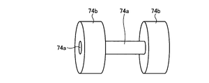
- FIG. 7 is a diagram illustrating an example of an internal structure of the fuse 74 used in the charge / discharge connector 44 in the charger / discharger 10 according to the first embodiment. In FIG. 7, elements other than the element 74a and the base 74b are omitted.
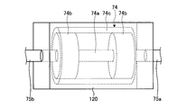
- FIG. 8 is a diagram illustrating an example of the structure of the fuse 74 used in the charge / discharge connector 44 in the charger / discharger 10 according to the first embodiment. In FIG. 8, elements other than the element 74a, the base 74b, and the cylindrical member 74c are omitted.
- FIG. 8 is a diagram illustrating an example of the structure of the fuse 74 used in the charge / discharge connector 44 in the charger / discharger 10 according to the first embodiment. In FIG. 8, elements other than the element 74a, the base 74b, and
- FIG. 9 is a diagram illustrating an example of a structure when the fuse 74 used in the charger / discharger 10 according to Embodiment 1 is covered with the insulating member 120.
- the radiator 122 and the insulating case 124 are omitted.
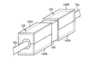
- FIG. 10 is a diagram illustrating an example of a structure when the fuse 74 used in the charger / discharger 10 according to the first embodiment is covered with the heat radiating body 122 after being covered with the insulating member 120.
- the insulating case 124 is omitted.
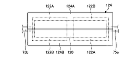
- FIG. 11 is a diagram illustrating an example of a structure when the fuse 74 used in the charger / discharger 10 according to the first embodiment is covered with the insulating member 120 and covered with the heat radiator 122 and then fixed with the insulating case 124. It is.
- the details of the configuration of the charge / discharge cable 42 and the charge / discharge connector 44 in the charger / discharger 10 will be described with reference to FIGS. 6 to 11.
- the charging / discharging cable 42 extends from the inside of the charger / discharger main body 10A, and serves as a path for the power supplied to the charger / discharger 10 or the power supplied from the charger / discharger 10 to the supply destination.
- the charge / discharge cable 42 includes a first electric wire 75a, a second electric wire 75b, and a third electric wire 75c that serve as a power path.
- the charge / discharge cable 42 further covers the first insulating layer that is insulated by covering the side surfaces of the first electric wire 75a, the second electric wire 75b, and the third electric wire 75c, and the side surface of the first insulating layer.
- a cabtire cable having a second insulating layer that is double-insulated is used.
- the charge / discharge cable 42 is preferably double-insulated, and thus has high electrical safety.
- the second insulating layer of the charge / discharge cable 42 is vinyl seeds in the first embodiment, but is not limited thereto, and may be rubber seeds.
- the case where the second insulating layer of the charge / discharge cable 42 is made of vinyl seeds is preferable because it is inexpensive, and the case where the second insulating layer is made of rubber is preferable because it is easy to handle at low temperatures.
- the first insulating layer of the charge / discharge cable 42 is made of vinyl and forms a heat-resistant vinyl electric wire, but is not limited thereto.
- the first insulating layer is made of rubber and may form a heat-resistant rubber electric wire.
- the first insulating layer is made of vinyl, it is preferable because it is inexpensive, and when it is made of rubber, it is preferable because it is easy to handle at low temperatures.
- the charge / discharge cable 42 preferably has a cross section of each wire in the range of 3.5 mm 2 or more and 14 mm 2 or less.
- the charge / discharge cable 42 is thinner than the electric wire having a cross section generally used for a quick charging cable of 22 mm 2 or more. It is lighter than the quick charging cable and is easier to handle at low temperatures than the quick charging cable. For this reason, when the cross section of each electric wire is in the range of 3.5 mm 2 or more and 14 mm 2 or less, the user can easily use the charge / discharge cable 42, which is preferable.
- the charge / discharge cable 42 is connected to the residential distribution board 28 even when the cross section of each electric wire is in the range of 3.5 mm 2 or more and 14 mm 2 or less, even when the voltage of the electric vehicle 12 is about 200V, for example. It is preferable because it can sufficiently withstand the electric capacity within the range of 3 kW or more and 12 kW or less exemplified as the total load capacity of a general household. The same applies to a case where a charge / discharge compatible plug-in hybrid car is connected to the charge / discharge cable 42 instead of the electric vehicle 12.
- a charge-discharge compatible plug-in hybrid car has a lower number of series-connected lithium ion batteries (LiB) generally used in an electric vehicle 12 than a general electric vehicle 12 in order to reduce the cost of a general-purpose product. Therefore, the total battery voltage is lower than that of a general electric vehicle 12.
- LiB lithium ion batteries
- the charging / discharging cable 42 is lighter than the quick charging cable and has a lower temperature than the quick charging cable because the cross section of each electric wire generally used for the quick charging cable is thinner than the electric wire of 22 mm 2 or more. Since the handling of the time is good, it is easy for the user to use and preferable.
- the charge / discharge connector 44 is provided at the end of the charge / discharge cable 42 opposite to the charger / discharger main body 10A.
- the charging / discharging connector 44 is insulated with the connector housing 114, the connector case 116, the connector pin 118, as shown in FIG. A member 120, a heat radiator 122, and an insulating case 124 are included.
- the side to which the electric vehicle 12 is connected is hereinafter referred to as a distal end side
- the side to which the charger / discharger body 10A is connected is referred to as a proximal end side in the following.
- the proximal end side of the first electric wire 75 a extends inside the charge / discharge cable 42.
- the distal end side of the first electric wire 75 a is electrically connected to one end of the fuse 74.
- the proximal end side of the second electric wire 75 b is electrically connected to the other end of the fuse 74.
- the distal end side of the second electric wire 75b is electrically connected to one end of the connector pin 118.
- the third electric wire 75c which is not shown in FIG. 6, is provided in parallel with the first electric wire 75a, the fuse 74, and the second electric wire 75b.
- the proximal end side of the third electric wire 75 c extends inside the charge / discharge cable 42.
- the proximal end side of the third electric wire 75 c is electrically connected to one end of a connector pin different from the connector pin 118.
- the connector housing 114 covers the connector pins 118 arranged on the front end side of the charge / discharge connector 44 from the outer periphery.
- the connector housing 114 has a shape that fits into the inlet 76 of the electric vehicle 12, and the charger housing 10 is fixed to the electric vehicle 12 by being fitted into the inlet 76.
- the connector housing 114 has a plurality of connector pins including connector pins 118 fixed therein.
- the connector case 116 is provided in a region from the proximal end portion of the connector housing 114 to the distal end portion of the charge / discharge cable 42.
- the connector case 116 includes a fuse 74 disposed on the proximal end side of the charge / discharge connector 44, a first electric wire 75 a, a second electric wire 75 b and a third electric wire 75 c, an insulating member 120, a radiator 122, and an insulating case 124. And from the outer periphery.
- the connector housing 114 and the connector case 116 preferably have insulating properties, flame resistance, drop resistance, and chemical resistance, and may be a resin having insulating properties, flame resistance, drop resistance, and chemical resistance. More preferred.
- the connector housing 114 and the connector case 116 are made of resin, they are reduced in weight, and thus are easy for the user to use and are preferable.
- the connector case 116 is preferable because it can reduce the user's feeling of being cold in a cold season such as winter as compared with the case where a material such as metal is used.
- the connector case 116 is preferable because it can be mass-produced relatively inexpensively using a mold as compared with the case where a material such as metal is used.
- the connector pin 118 is fixed inside the connector housing 114.
- the connector pin 118 is made of metal and has electrical conductivity.
- the distal end side of the connector pin 118 is exposed inside the connector housing 114.
- the proximal end side of the connector pin 118 is electrically connected to the second electric wire 75b.
- the proximal end side of the connector pin 118 is connected to the second electric wire 75b by, for example, crimping.
- the connector pin 118 is electrically connected to the electric vehicle 12 side electric wire fixed to the inlet 76 by fitting the connector housing 114 to the inlet 76 of the electric vehicle 12. Thereby, the charger / discharger 10 is electrically connected to the electric vehicle 12.
- the fuse 74 has two terminals. Inside the connector case 116, the terminal on the proximal end side of the fuse 74 is electrically connected to the first electric wire 75a. A terminal on the tip side of the fuse 74 is electrically connected to the second electric wire 75b. Each terminal of the fuse 74 is electrically and mechanically connected to the first electric wire 75a and the second electric wire 75b with a material having electrical conductivity, for example, solder.
- the fuse 74 includes an element 74a, a base 74b, and a cylindrical member 74c.
- the element 74a has electrical conductivity. One end of the element 74a is connected to the first electric wire 75a by, for example, solder. The other end of the element 74a is connected to the second electric wire 75b by, for example, solder.
- the element 74a serves as a power path together with the first electric wire 75a and the second electric wire 75b in normal times.
- the element 74a protects the electric circuit connected to the first electric wire 75a and the second electric wire 75b by fusing by Joule heat when a current greater than or equal to the rated current flows due to some abnormality, thereby opening the circuit.
- the base 74b is a cylindrical metal member having electrical conductivity. As shown in FIG. 7, the caps 74b are provided at two locations so as to cover both ends of the element 74a.
- the base 74b is fixed to each end of the element 74a with a material having electrical conductivity, for example, solder. Thereby, the cap 74b is electrically connected to the element 74a, the first electric wire 75a, and the second electric wire 75b.
- the cylindrical member 74c is a cylindrical ceramic member having electrical insulation. As shown in FIG. 8, the inner peripheral sides of both ends in the axial direction of the cylindrical member 74c are mechanically fixed to the outer peripheral portion of each base 74b with, for example, an adhesive.
- the insulating member 120 is in contact with almost the entire surface of the fuse 74 in which both ends of the element 74a are connected to the first electric wire 75a and the second electric wire 75b with a material having electrical conductivity. Molded to cover.
- the insulating member 120 has electrical insulation and heat dissipation.
- the insulating member 120 is insert-molded into the mold after the fuse 74 having the first electric wire 75a and the second electric wire 75b connected to both ends is placed inside the mold. That is, the insulating member 120 is molded.
- the insulating member 120 is formed so as to contact almost the entire surface of the fuse 74 and cover the fuse 74. Therefore, the insulating member 120 can quickly dissipate heat generated near the fuse 74 to the outside of the fuse 74.
- the heat generated in the vicinity of the fuse 74 includes the heat generated by the element 74a and the heat generated by the solder connecting the first electric wire 75a and the second electric wire 75b to the element 74a.
- the material of the insulating member 120 is exemplified by an unsaturated polyester resin containing a glass filler that can be molded with high accuracy at a relatively low temperature of 120 ° C. or higher and 160 ° C. or lower.
- the material of the insulating member 120 is not limited to the exemplified material, and may be any material that can be molded in the temperature range described above.
- the material of the insulating member 120 is an unsaturated polyester resin containing glass filler, it is preferable because the heat-resistant temperature rises due to a chemical reaction in the process of insert molding.
- the linear expansion coefficient is a value close to that of a metal or ceramic as compared with a general resin material. As a result, the stress generated between the insulating member 120 and the fuse 74 is reduced, which is preferable.
- the material of the insulating member 120 is an unsaturated polyester resin containing glass filler
- it can be molded at a relatively low temperature such as 120 ° C. or higher and 160 ° C. or lower, so that the stress generated between the insulating member 120 and the fuse 74 is further reduced. Therefore, it is preferable.
- the stress generated in the insulating member 120 and the fuse 74 is reduced, so that deterioration of the element 74a due to molding is reduced.
- the insulating member 120 is insert-molded in the mold, but is not limited thereto, and has any form of electric insulation and heat dissipation, and provided in the fuse 74 so as to cover the fuse 74. There may be.
- the outer periphery of the insulating member 120 is covered with a radiator 122 as shown in FIG.
- the radiator 122 has a heat dissipation property.
- the heat radiator 122 preferably has electrical conductivity.
- the heat radiator 122 is more preferably a metal.
- the heat dissipator 122 is provided at two locations on the fuse 74, the first electric wire 75 a side and the second electric wire 75 b side, so as to cover the portions of the caps 74 b of the fuse 74 from the outer periphery of the insulating member 120. Provided.
- the heat dissipator 122 Since the heat dissipator 122 is in contact with the insulating member 120 only, the element 74a, the base 74b, the first electric wire 75a, and the second electric wire 75b are electrically insulated. Therefore, the heat radiator 122 does not serve as a power path. In addition, since the radiator 122 is provided in two locations so as to cover the caps 74b, one of the radiators 122 and 122 is short-circuited with the cap 74b, the first electric wire 75a, or the second electric wire 75b. Even in this case, the function of the fuse 74 is not hindered because it does not become a power path.
- Each of the heat radiators 122 and 122 is divided into two along the direction in which the element 74a of the fuse 74 extends.
- Each of the radiators 122, 122 has a pair of first radiator member 122A and second radiator member 122B that can be fitted together.
- the first radiator member 122A and the second radiator member 122B are formed by combining a plurality of radiator plates.
- the first heat radiating member 122A can be fitted to the second heat radiating member 122B and can be detached from the second heat radiating member 122B. Therefore, the heat radiator 122 is preferable because it makes it easy for the user to replace the fuse 74 when the element 74a of the fuse 74 is melted.
- the heat dissipating body 122 is in contact with almost the entire outer periphery of the insulating member 120 so as to cover the caps 74b, heat generated in the vicinity of the fuse 74 can be quickly dissipated out of the insulating member 120. Thereby, since the heat radiator 122 can reduce the progress of crystallization of the soluble body tissue in the element 74a due to repeated heating, it is possible to suppress a decrease in durability of the fuse 74 due to a crack generated from the crystal interface of the soluble body tissue.
- the outer periphery of the heat radiating body 122 is covered and fixed with an insulating case 124 as shown in FIG.
- the insulating case 124 has electrical insulation and heat dissipation.
- the insulating case 124 preferably has flame retardancy. As shown in FIG. 11, the insulating case 124 is provided so as to cover the outer periphery of the radiator 122.
- the insulating case 124 is divided into two along the direction in which the element 74a of the fuse 74 extends.
- the insulating case 124 has a pair of first insulating case member 124A and second insulating case member 124B that can be fitted together.
- the first insulating case member 124A and the second insulating case member 124B are formed by combining a plurality of insulating sheets having electrical insulating properties and heat dissipation properties.
- the first insulating case member 124A can be fitted into the second insulating case member 124B and can be detached from the second insulating case member 124B. Therefore, the insulating case 124 is preferable because it makes it easy for the user to replace the fuse 74 when the element 74a of the fuse 74 is melted.
- the insulation case 124 contacts almost the entire outer periphery of the heat radiating body 122, heat generated in the vicinity of the fuse 74 can be quickly radiated out of the heat radiating body 122. Since the insulating case 124 also contacts a region of the outer periphery of the insulating member 120 where the heat radiating body 122 is not covered, heat generated in the vicinity of the fuse 74 can be quickly radiated out of the insulating member 120. Thereby, since the insulation case 124 can reduce the progress of crystallization of the soluble body tissue in the element 74a due to repeated heating, it is possible to suppress a decrease in durability of the fuse 74 due to a crack generated from the crystal interface of the soluble body tissue.
- the insulating case 124 has electrical insulation and heat dissipation, and covers the entire outer periphery of the radiator 122, so that the outer periphery of the radiator 122 can be insulated and protected.
- the insulating member 120 is formed so as to contact almost the entire outer periphery of the fuse 74 and cover the fuse 74 inside the charge / discharge connector 44. ing.
- a heat radiator 122 is provided on the insulating member 120 so as to be in contact with substantially the entire outer periphery of the insulating member 120 and cover the insulating member 120.
- An insulating case 124 is provided on the heat radiating body 122 so as to be in contact with substantially the entire outer periphery of the heat radiating body 122 and cover the heat radiating body 122.
- each of the insulating member 120, the radiator 122, and the insulating case 124 can quickly radiate heat generated near the fuse 74 to the outside of the fuse 74.
- the charger / discharger 10 according to the first embodiment can reduce the progress of crystallization of the soluble body tissue in the element 74a due to repeated heating, and thus the durability of the fuse 74 due to cracks generated from the crystal interface of the soluble body tissue. The decline in sex can be suppressed.
- the charger / discharger 10 according to Embodiment 1 has high electrical safety because the element 74a and the base 74b of the fuse 74 are double-insulated by the insulating member 120 and the insulating case 124.
- the first electric wire 75a, the second electric wire 75b, and the third electric wire 75c in the charge / discharge cable 42 are all double-insulated with the first insulating layer and the second insulating layer. Therefore, electrical safety is high. Therefore, in the charger / discharger 10 according to the first exemplary embodiment, the connector case 116 may be made of an electrically conductive material having no insulating property, that is, a metal.
- the connector case 116 is preferable because it can quickly dissipate heat generated near the fuse 74 to the outside.
- the charger / discharger 10 according to the first embodiment can further reduce the progress of crystallization of the soluble body tissue in the element 74a due to repeated heating, and thus the fuse 74 due to cracks generated from the crystal interface of the soluble body tissue. A decrease in durability can be further suppressed.
- the charger / discharger 10 according to the first embodiment is not arranged in a state where the fuse 74 is floated as in the prior art, and is fixed by the insulating member 120, the radiator 122, and the insulating case 124. Therefore, since the charger / discharger 10 according to the first embodiment is radiated only by the first electric wire 75a, the second electric wire 75b, and air as in the prior art, the heat radiation efficiency does not decrease.
- the charger / discharger 10 according to Embodiment 1 Since the charger / discharger 10 according to Embodiment 1 has high heat dissipation performance, it is not necessary to make a hole in the connector housing 114 or the connector case 116 in order to dissipate the fuse 74. Therefore, in the charger / discharger 10 according to the first exemplary embodiment, the connector lock mechanism provided in the connector housing 114 or the connector case 116 may cause problems such as malfunction of the mechanism due to intrusion of dust, metal pieces, insects, and the like. It can be suppressed. Further, the charger / discharger 10 according to the first embodiment does not need to make a hole in the connector housing 114 or the connector case 116 in order to dissipate the fuse 74.
- the charger / discharger 10 disassembles the connector housing 114 or the connector case 116 and performs cleaning to remove dust, metal pieces, insects, and the like from the connector housing 114 or the connector case 116. Since it is not necessary to perform maintenance, it is easy to use for general users who are difficult to perform maintenance at all times.
- the charger / discharger 10 according to the first embodiment is used in an environment that is repeatedly heated at a low temperature. However, since the decrease in the durability of the fuse 74 is reduced as described above, the soluble body tissue in the element 74a. It is not necessary to use a fuse having a fusing current larger than the rated current on the assumption that the durability of the fuse 74 is lowered as the crystallization progresses. Therefore, the charger / discharger 10 according to the first embodiment can use the fuse 74 having a fusing current that matches the rated current. Thereby, the charger / discharger 10 according to the first embodiment can use the charging / discharging cable 42 thinner than the conventional one in accordance with the fusing current of the fuse 74 according to the rated current.
- the charger / discharger 10 according to the first embodiment is light in weight, can be easily handled at low temperatures, and can be provided that is particularly easy for general users to use. That is, the charger / discharger 10 according to the first embodiment can easily handle the cable while sufficiently protecting the fuse provided between the cables.
- FIG. FIG. 12 is a cross-sectional view showing an example of the configuration of the charge / discharge cable 42 and the charge / discharge connector 44a in the charger / discharger according to the second embodiment.
- the charger / discharger 10 according to the first embodiment is a stress relaxation resin between the cylindrical member 74c of the fuse 74 provided inside the charge / discharge connector 44a and the insulating member 120.
- 126, and the first electric wire 75a or the second electric wire 75b, the element 74a, and the base 74b are connected at a welded portion exemplified by TIG (Tungsten Inert Gas) welding.
- TIG Transmissionungsten Inert Gas
- the stress relaxation resin 126 is provided between the cylindrical member 74 c of the fuse 74 and the insulating member 120. Specifically, the stress relaxation resin 126 is applied and provided on the outer peripheral portion of the cylindrical member 74c, and then the insulating member 120 is formed on the outer periphery, so that the stress relaxing resin 126 is disposed between the cylindrical member 74c and the insulating member 120. Is done.
- the stress relaxation resin 126 has a property that it is easier to extend than the fuse 74 with respect to applied stress.
- the stress relaxation resin 126 preferably has electrical insulation.
- the charger / discharger according to the second embodiment can reduce the mechanical stress of the fuse 74 caused by this stress, and can reduce the mechanical deterioration due to the mechanical stress of the fuse 74. .
- the first electric wire 75a or the second electric wire 75b, the element 74a, and the base 74b are connected by a welded portion. That is, in the charger / discharger according to Embodiment 2, the first welded portion is provided between the first electric wire 75a and the element 74a, and the second welded portion is provided between the second electric wire 75b and the element 74a. The third welding portion is provided between the element 74a and each of the caps 74b. Each of the first welded portion, the second welded portion, and the third welded portion has higher heat resistance than solder, and has high durability against thermal stress received when heating and cooling are repeated.
- the charger / discharger according to the second embodiment has high heat resistance and high durability against thermal stress generated between the element 74a and the first electric wire 75a or the second electric wire 75b by repeated heating and cooling. Therefore, since the charger / discharger according to the second embodiment can maintain the durability of the fuse 74 for a long time even if a plurality of materials are used for the fuse 74 for the purpose of heat dissipation, the durable power supply system 1 is provided. Can be built.
- the stress relaxation resin 126 is applied to the outer peripheral portion of the cylindrical member 74c, but is not limited thereto.
- a heat-shrinkable tube is provided on the outer periphery of the cylindrical member 74c, and the stress relaxation member 126 is provided. The same effect can be obtained.
- the configurations shown in the first embodiment and the second embodiment are examples of the contents of the present invention, and can be combined with other known techniques and do not depart from the gist of the present invention. It is also possible to omit or change part of the configuration within the scope.
Landscapes
- Engineering & Computer Science (AREA)
- Power Engineering (AREA)
- Charge And Discharge Circuits For Batteries Or The Like (AREA)
- Emergency Protection Circuit Devices (AREA)
- Protection Of Static Devices (AREA)
- Supply And Distribution Of Alternating Current (AREA)
- Electric Propulsion And Braking For Vehicles (AREA)
Abstract
Une unité de charge/décharge (10) charge une batterie principale (80) placée à l'intérieur d'un véhicule électrique (12) à l'aide d'un système électrique commercial (14) ou d'une batterie solaire (20) ou décharge l'énergie chargée dans la batterie principale (80) vers une charge externe connectée à un tableau de distribution interne (28). L'unité de charge/décharge (10) est pourvu : d'un corps principal d'unité de charge/décharge (10A) ; d'un câble de charge/décharge (42) ; et d'un connecteur de charge/décharge (44) connecté électriquement au véhicule électrique (12). Le corps principal d'unité de charge/décharge (10A) est pourvu d'un convertisseur de puissance (30). Le connecteur de charge/décharge (44) comporte : un premier fil électrique (75a) s'étendant depuis l'intérieur du câble de charge/décharge (42) ; un fusible (74) connecté à une extrémité du premier fil électrique (75a) ; un second fil électrique (75b) connecté au fusible (74) sur le côté opposé au premier fil électrique (75a) ; et un élément isolant (120) ayant des propriétés d'isolation électrique et des propriétés de dissipation de chaleur et recouvrant le fusible (74) tout en entrant en contact avec le fusible (74).
Priority Applications (2)
| Application Number | Priority Date | Filing Date | Title |
|---|---|---|---|
| PCT/JP2016/056813 WO2017149763A1 (fr) | 2016-03-04 | 2016-03-04 | Unité de charge/décharge |
| JP2018502481A JP6674015B2 (ja) | 2016-03-04 | 2016-03-04 | 充放電器 |
Applications Claiming Priority (1)
| Application Number | Priority Date | Filing Date | Title |
|---|---|---|---|
| PCT/JP2016/056813 WO2017149763A1 (fr) | 2016-03-04 | 2016-03-04 | Unité de charge/décharge |
Publications (1)
| Publication Number | Publication Date |
|---|---|
| WO2017149763A1 true WO2017149763A1 (fr) | 2017-09-08 |
Family
ID=59742625
Family Applications (1)
| Application Number | Title | Priority Date | Filing Date |
|---|---|---|---|
| PCT/JP2016/056813 Ceased WO2017149763A1 (fr) | 2016-03-04 | 2016-03-04 | Unité de charge/décharge |
Country Status (2)
| Country | Link |
|---|---|
| JP (1) | JP6674015B2 (fr) |
| WO (1) | WO2017149763A1 (fr) |
Cited By (3)
| Publication number | Priority date | Publication date | Assignee | Title |
|---|---|---|---|---|
| WO2021090520A1 (fr) * | 2019-11-07 | 2021-05-14 | 三菱電機株式会社 | Dispositif de conversion de puissance |
| JP2022116806A (ja) * | 2021-01-29 | 2022-08-10 | トヨタホーム株式会社 | 建物の給電システム |
| WO2023080549A1 (fr) * | 2021-11-02 | 2023-05-11 | 피에스케이 주식회사 | Ensemble connecteur et appareil de traitement de substrat le comprenant |
Citations (4)
| Publication number | Priority date | Publication date | Assignee | Title |
|---|---|---|---|---|
| JPS52142254A (en) * | 1977-05-19 | 1977-11-28 | Matsushita Electric Industrial Co Ltd | Temperature fuse |
| JPS60236430A (ja) * | 1985-04-17 | 1985-11-25 | 日本高圧電気株式会社 | 密閉形電線ヒユーズにおける絶縁ケースの成形法 |
| JPS6220446U (fr) * | 1985-07-19 | 1987-02-06 | ||
| JP2014226014A (ja) * | 2013-04-24 | 2014-12-04 | パナソニックIpマネジメント株式会社 | 電力変換システムおよびコネクタ |
Family Cites Families (3)
| Publication number | Priority date | Publication date | Assignee | Title |
|---|---|---|---|---|
| GB8711828D0 (en) * | 1987-05-19 | 1987-06-24 | Brush Fusegear Ltd | Fuse |
| WO2013176139A1 (fr) * | 2012-05-21 | 2013-11-28 | 住電朝日精工株式会社 | Connecteur |
| JP6117013B2 (ja) * | 2013-06-20 | 2017-04-19 | 矢崎総業株式会社 | シールドコネクタ |
-
2016
- 2016-03-04 WO PCT/JP2016/056813 patent/WO2017149763A1/fr not_active Ceased
- 2016-03-04 JP JP2018502481A patent/JP6674015B2/ja not_active Expired - Fee Related
Patent Citations (4)
| Publication number | Priority date | Publication date | Assignee | Title |
|---|---|---|---|---|
| JPS52142254A (en) * | 1977-05-19 | 1977-11-28 | Matsushita Electric Industrial Co Ltd | Temperature fuse |
| JPS60236430A (ja) * | 1985-04-17 | 1985-11-25 | 日本高圧電気株式会社 | 密閉形電線ヒユーズにおける絶縁ケースの成形法 |
| JPS6220446U (fr) * | 1985-07-19 | 1987-02-06 | ||
| JP2014226014A (ja) * | 2013-04-24 | 2014-12-04 | パナソニックIpマネジメント株式会社 | 電力変換システムおよびコネクタ |
Cited By (6)
| Publication number | Priority date | Publication date | Assignee | Title |
|---|---|---|---|---|
| WO2021090520A1 (fr) * | 2019-11-07 | 2021-05-14 | 三菱電機株式会社 | Dispositif de conversion de puissance |
| JP2021078203A (ja) * | 2019-11-07 | 2021-05-20 | 三菱電機株式会社 | 電力変換装置 |
| US12113451B2 (en) | 2019-11-07 | 2024-10-08 | Mitsubishi Electric Corporation | Power conversion device and arrangement of a wire therein |
| JP2022116806A (ja) * | 2021-01-29 | 2022-08-10 | トヨタホーム株式会社 | 建物の給電システム |
| JP7621810B2 (ja) | 2021-01-29 | 2025-01-27 | トヨタホーム株式会社 | 建物の給電システム |
| WO2023080549A1 (fr) * | 2021-11-02 | 2023-05-11 | 피에스케이 주식회사 | Ensemble connecteur et appareil de traitement de substrat le comprenant |
Also Published As
| Publication number | Publication date |
|---|---|
| JPWO2017149763A1 (ja) | 2018-07-19 |
| JP6674015B2 (ja) | 2020-04-01 |
Similar Documents
| Publication | Publication Date | Title |
|---|---|---|
| JP6611917B2 (ja) | 充放電器 | |
| JP6749442B2 (ja) | 一体型電源ボックス | |
| JP5752151B2 (ja) | 電池の内部抵抗を使用して動作性能を改善するための電池パックシステム | |
| KR200491964Y1 (ko) | 배터리 디스커넥트 유닛 | |
| US20150229011A1 (en) | Battery System and Motor Vehicle | |
| JP4550078B2 (ja) | 熱収縮チューブを用いた安全スイッチ及びこれを含む二次電池 | |
| US20200335737A1 (en) | Thermal runaway mitigation system for high capacity energy cell | |
| KR101853397B1 (ko) | 전지모듈 | |
| US20120034501A1 (en) | Battery Pack Configuration to Reduce Hazards Associated with Internal Short Circuits | |
| JP2010178402A (ja) | 二次電池保護回路 | |
| KR20140084824A (ko) | 차량용 배터리모듈의 안전장치 | |
| CN103123995B (zh) | 一种车用电池加热保温系统 | |
| KR101926341B1 (ko) | 태양광 발전설비용 배터리 관리 시스템 | |
| JP6674015B2 (ja) | 充放電器 | |
| CN120657393A (zh) | 电池模块、包含该电池模块的电池架和能量存储设备 | |
| WO2020134815A1 (fr) | Dispositif de conversion et de commande d'électricité et système de stockage d'énergie comprenant le dispositif | |
| CN108682887B (zh) | 一种电池模组和动力电池系统 | |
| KR20110076860A (ko) | 향상된 안전성의 이차전지 | |
| CN204681081U (zh) | 一种锂电型太阳能路灯对锂电池安全充电保护电路 | |
| CN108550750B (zh) | 加热温度可控的电池包及电池包系统 | |
| JP2001006639A (ja) | リチウムイオン二次電池パック | |
| JP7420129B2 (ja) | リレーユニット | |
| CN108879031A (zh) | 一种用于电动车电池的加热保温系统 | |
| KR101541367B1 (ko) | 안전성을 위한 스위치를 포함하고 있는 에너지 저장 시스템 | |
| CN105336907B (zh) | 电动汽车电池组内电池箱或电池模组之间的电接头结构 |
Legal Events
| Date | Code | Title | Description |
|---|---|---|---|
| ENP | Entry into the national phase |
Ref document number: 2018502481 Country of ref document: JP Kind code of ref document: A |
|
| NENP | Non-entry into the national phase |
Ref country code: DE |
|
| 121 | Ep: the epo has been informed by wipo that ep was designated in this application |
Ref document number: 16892603 Country of ref document: EP Kind code of ref document: A1 |
|
| 122 | Ep: pct application non-entry in european phase |
Ref document number: 16892603 Country of ref document: EP Kind code of ref document: A1 |