WO2017149786A1 - Appareil de massage - Google Patents
Appareil de massage Download PDFInfo
- Publication number
- WO2017149786A1 WO2017149786A1 PCT/JP2016/062054 JP2016062054W WO2017149786A1 WO 2017149786 A1 WO2017149786 A1 WO 2017149786A1 JP 2016062054 W JP2016062054 W JP 2016062054W WO 2017149786 A1 WO2017149786 A1 WO 2017149786A1
- Authority
- WO
- WIPO (PCT)
- Prior art keywords
- massage
- rotating
- pair
- massage machine
- rotating shaft
- Prior art date
- Legal status (The legal status is an assumption and is not a legal conclusion. Google has not performed a legal analysis and makes no representation as to the accuracy of the status listed.)
- Ceased
Links
Images



Classifications
-
- A—HUMAN NECESSITIES
- A61—MEDICAL OR VETERINARY SCIENCE; HYGIENE
- A61H—PHYSICAL THERAPY APPARATUS, e.g. DEVICES FOR LOCATING OR STIMULATING REFLEX POINTS IN THE BODY; ARTIFICIAL RESPIRATION; MASSAGE; BATHING DEVICES FOR SPECIAL THERAPEUTIC OR HYGIENIC PURPOSES OR SPECIFIC PARTS OF THE BODY
- A61H7/00—Devices for suction-kneading massage; Devices for massaging the skin by rubbing or brushing not otherwise provided for
- A61H7/007—Kneading
-
- A—HUMAN NECESSITIES
- A61—MEDICAL OR VETERINARY SCIENCE; HYGIENE
- A61H—PHYSICAL THERAPY APPARATUS, e.g. DEVICES FOR LOCATING OR STIMULATING REFLEX POINTS IN THE BODY; ARTIFICIAL RESPIRATION; MASSAGE; BATHING DEVICES FOR SPECIAL THERAPEUTIC OR HYGIENIC PURPOSES OR SPECIFIC PARTS OF THE BODY
- A61H15/00—Massage by means of rollers, balls, e.g. inflatable, chains, or roller chains
- A61H2015/0007—Massage by means of rollers, balls, e.g. inflatable, chains, or roller chains with balls or rollers rotating about their own axis
- A61H2015/0014—Massage by means of rollers, balls, e.g. inflatable, chains, or roller chains with balls or rollers rotating about their own axis cylinder-like, i.e. rollers
-
- A—HUMAN NECESSITIES
- A61—MEDICAL OR VETERINARY SCIENCE; HYGIENE
- A61H—PHYSICAL THERAPY APPARATUS, e.g. DEVICES FOR LOCATING OR STIMULATING REFLEX POINTS IN THE BODY; ARTIFICIAL RESPIRATION; MASSAGE; BATHING DEVICES FOR SPECIAL THERAPEUTIC OR HYGIENIC PURPOSES OR SPECIFIC PARTS OF THE BODY
- A61H2201/00—Characteristics of apparatus not provided for in the preceding codes
- A61H2201/01—Constructive details
- A61H2201/0192—Specific means for adjusting dimensions
-
- A—HUMAN NECESSITIES
- A61—MEDICAL OR VETERINARY SCIENCE; HYGIENE
- A61H—PHYSICAL THERAPY APPARATUS, e.g. DEVICES FOR LOCATING OR STIMULATING REFLEX POINTS IN THE BODY; ARTIFICIAL RESPIRATION; MASSAGE; BATHING DEVICES FOR SPECIAL THERAPEUTIC OR HYGIENIC PURPOSES OR SPECIFIC PARTS OF THE BODY
- A61H2201/00—Characteristics of apparatus not provided for in the preceding codes
- A61H2201/16—Physical interface with patient
- A61H2201/1602—Physical interface with patient kind of interface, e.g. head rest, knee support or lumbar support
- A61H2201/164—Feet or leg, e.g. pedal
-
- A—HUMAN NECESSITIES
- A61—MEDICAL OR VETERINARY SCIENCE; HYGIENE
- A61H—PHYSICAL THERAPY APPARATUS, e.g. DEVICES FOR LOCATING OR STIMULATING REFLEX POINTS IN THE BODY; ARTIFICIAL RESPIRATION; MASSAGE; BATHING DEVICES FOR SPECIAL THERAPEUTIC OR HYGIENIC PURPOSES OR SPECIFIC PARTS OF THE BODY
- A61H2201/00—Characteristics of apparatus not provided for in the preceding codes
- A61H2201/16—Physical interface with patient
- A61H2201/1657—Movement of interface, i.e. force application means
- A61H2201/1671—Movement of interface, i.e. force application means rotational
-
- A—HUMAN NECESSITIES
- A61—MEDICAL OR VETERINARY SCIENCE; HYGIENE
- A61H—PHYSICAL THERAPY APPARATUS, e.g. DEVICES FOR LOCATING OR STIMULATING REFLEX POINTS IN THE BODY; ARTIFICIAL RESPIRATION; MASSAGE; BATHING DEVICES FOR SPECIAL THERAPEUTIC OR HYGIENIC PURPOSES OR SPECIFIC PARTS OF THE BODY
- A61H2201/00—Characteristics of apparatus not provided for in the preceding codes
- A61H2201/16—Physical interface with patient
- A61H2201/1683—Surface of interface
- A61H2201/169—Physical characteristics of the surface, e.g. material, relief, texture or indicia
- A61H2201/1695—Enhanced pressure effect, e.g. substantially sharp projections, needles or pyramids
-
- A—HUMAN NECESSITIES
- A61—MEDICAL OR VETERINARY SCIENCE; HYGIENE
- A61H—PHYSICAL THERAPY APPARATUS, e.g. DEVICES FOR LOCATING OR STIMULATING REFLEX POINTS IN THE BODY; ARTIFICIAL RESPIRATION; MASSAGE; BATHING DEVICES FOR SPECIAL THERAPEUTIC OR HYGIENIC PURPOSES OR SPECIFIC PARTS OF THE BODY
- A61H2205/00—Devices for specific parts of the body
- A61H2205/10—Leg
- A61H2205/106—Leg for the lower legs
-
- A—HUMAN NECESSITIES
- A61—MEDICAL OR VETERINARY SCIENCE; HYGIENE
- A61H—PHYSICAL THERAPY APPARATUS, e.g. DEVICES FOR LOCATING OR STIMULATING REFLEX POINTS IN THE BODY; ARTIFICIAL RESPIRATION; MASSAGE; BATHING DEVICES FOR SPECIAL THERAPEUTIC OR HYGIENIC PURPOSES OR SPECIFIC PARTS OF THE BODY
- A61H2205/00—Devices for specific parts of the body
- A61H2205/12—Feet
Definitions
- the present invention relates to a massage machine for performing massage on a user's treatment part (for example, lower limbs), and in particular, when the width (size, thickness) of the treatment part varies depending on the user's physique.
- the present invention relates to a massage machine that can provide a comfortable massage.
- Patent Document 1 there is one disclosed in Patent Document 1 as a massage machine including a pair of left and right massage members arranged so as to sandwich a treatment part such as a lower limb (foot or calf).
- the pair of left and right massage members are driven so as to be close to and away from each other, and by repeatedly pressing the treatment part from both the left and right sides and releasing the pressure, massage operation by itch is performed. Yes.
- a drive mechanism provided in the massage machine includes a rotation shaft provided in a direction penetrating between the pair of left and right massage members, a drive unit that rotationally drives the rotation shaft, and the rotational force of the rotation shaft in the proximity of the pair of left and right massage members. It has a pair of left and right converting portions that convert to a separating operation, and an eccentric rotor that is provided so as to be able to rotate integrally with the rotating shaft in order to transmit the rotational force of the rotating shaft to the pressing member.
- a drive mechanism provided in a conventional massage machine is a device that performs a massage operation of a pair of left and right massage members via a pair of left and right conversion units using rotation of a rotating shaft as a drive source, for example, sandwiching a left leg of a user
- the left-right width of the pair of massage members is constant. That is, the massage member oscillates during driving and its interval is variable, but its variable width is constant.
- the present invention has been made in view of the above circumstances, and enables effective massage treatment with a pair of left and right massage members even for a user having treatment sections of various sizes and thicknesses.
- the purpose is to provide a massage machine.
- the massage machine includes a pair of left and right massage members arranged so as to sandwich the treatment portion, a rotation shaft provided so as to penetrate the massage member across the left and right, and the rotation shaft.
- a massage machine having a drive unit that drives and a conversion unit that converts the rotational force of the rotation shaft into a massage operation by the massage member, by rotating the rotation shaft, at least one of the pair of left and right massage members Comprises a horizontal movement mechanism that moves in the horizontal direction along the rotation axis and in which the distance between the pair of left and right massage members is variable.
- the converting portion is fixed to rotate integrally with the rotation shaft, and has a fixed rotation boss portion having an endless cam surface that is inclined with respect to the rotation shaft, and a base of the massage member.
- An annular fitting portion that is formed at the end portion and is slidably fitted to the periphery of the rotating boss portion; and a restricting portion that restricts the annular fitting portion from rotating around the rotating boss portion. It is good to have.
- the conversion unit is movable in a predetermined range on the rotating shaft along the axial direction of the rotating shaft, and an endless cam surface inclined with respect to the rotating shaft is formed on the periphery.
- the horizontal movement mechanism includes a screw screw portion formed on the rotation shaft, and a moving rotation boss portion in which a spiral inner tooth screwed with the screw screw portion is formed on an inner peripheral surface of a central portion. It is good to have.
- the movable rotating boss portion is configured to rotate integrally with the rotating shaft when reaching one end or the other end of the screw thread portion.
- the screw screw portion of the horizontal movement mechanism is formed on both ends in the left-right direction of the rotating shaft, and the screw screw portion on one side and the screw screw portion on the other side are in a reverse screw relationship. It is good to be.
- a pressing member is disposed between the pair of left and right massage members, the pressing member is configured to cover a rotation shaft, and the pressing member is moved along with the movement of the movable rotating boss portion. It is good to be configured to expand and contract in the horizontal direction.
- the massage machine according to the present invention enables effective massage treatment with a pair of left and right massage members, even for users having treatment sections of various sizes and thicknesses.
- the massage machine according to the present embodiment is a lower limb massage machine 1 (sometimes simply referred to as a massage machine 1) having a lower limb L as a treatment portion.
- a subject of massage it is comprised so that the massage of a itch can be provided to both the calf which comprises the leg L, and a leg part.
- the massage machine 1 includes a massage member 2 that performs massage of massage and a drive unit 5 that drives the massage member 2.
- calf refers to a portion of a human lower limb L above the ankle that comes under the knee
- foot refers to a portion below the ankle.
- FIG. 1 illustrates the front-rear direction, the left-right direction (width direction), and the up-down direction of the massage machine 1 used in the description, and this direction coincides with the left-right, front-rear, up-down direction as viewed from the user. .
- the massage machine 1 of the present embodiment has a base 3 that can be placed on a floor or the like in a substantially rectangular plate shape, and a foot or a calf is fitted on the upper surface of the base 3.
- a pair of left and right massage members 2 arranged side by side in the right and left direction, a pressing member 4 (foot massage body) disposed between the pair of left and right massage members 2, and a pair of left and right massage members 2
- a drive unit 5 for bringing the two close to and away from each other.
- the pair of left and right massage members 2 are respectively provided on the right side and the left side on the base 3 so as to correspond to the right leg L and the left leg L of the user.
- the massage member 2 is formed in a plate-like shape standing by a material having elasticity in the thickness direction, and a cushion material, a cover material, or the like that softens the feeling of contact with the foot is provided on the inner surfaces of the massage member 2 facing each other. May be.
- the drive unit 5 massages the foot part by squeezing the pair of left and right massage members 2 by reciprocating between the holding position of the foot part inserted between them and the release position. Is given.
- the drive unit 5 is configured to drive a pair of left and right massage members 2 corresponding to the right lower limb L and a pair of left and right massage members 2 corresponding to the left lower limb L at the same time.
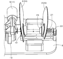
- the drive unit 5 includes one rotary shaft 10 provided in a direction (left-right direction) penetrating between the massage members 2, a drive motor 11 that rotationally drives the rotary shaft 10, and the rotational force of the rotary shaft 10. And a pair of conversion units 12 for converting the massage into a massage operation by the massage member 2.
- the drive motor 11 can be switched between forward rotation drive and reverse rotation drive, and transmits the rotational drive force to the rotary shaft 10 via a speed reducer 13 incorporating a worm gear and a worm wheel meshing with the worm gear. It is like that.
- the conversion unit 12 is provided in a portion where the rotary shaft 10 penetrates the massage member 2, and has an inclined rotor 14 that is fixed to the rotary shaft 10 in a skewered manner and rotates integrally with the rotary shaft 10.
- the inclined rotor 14 is configured such that an annular fitting portion 15 provided at the base end of the massage member 2 is fitted from the outside through a bearing that is fitted on the outer periphery of the inclined rotor 14.
- the inclined cam surface formed on the outer periphery of the inclined rotor 14 and the annular fitting portion 15 are rotatable via a bearing, and the massage member 2 maintains a state of being rotatable relative to the rotary shaft 10. It is like that.
- the conversion unit 12 has a structure in which a regulation protrusion 16 that protrudes downward from the massage member 2 is engaged with a lateral groove body 17 that is installed on the base 3 in the left-right direction. Since the restricting protrusion 16 and the lateral groove body 17 (laterally long hole) are engaged with each other, the massage member 2 does not rotate (followed rotation) with the inclined rotor 14. That is, when the rotating shaft 10 rotates, the inclined rotor 14 causes vibration according to the inclination component around the rotating shaft 10, and only the vibration component at this time is transmitted to the massage member 2. It has become.
- the inclination direction in which the inclined rotor 14 is inclined with respect to the rotary shaft 10 is set so as to be in the opposite direction between the pair of massage members 2. Therefore, when the rotating shaft 10 is rotated when the front upper edge and the rear upper edge of the massage member 2 are separated from each other, the front upper edge side of the massage member 2 gradually approaches and the front side of the massage member 2 The lower edge side is separated, and then the nipping operation is performed so that the rear upper edge side of the massage member 2 gradually approaches.
- the massage member 2 swings in a wavy manner under a condition restricted to a predetermined angle range while alternately repeating the sandwiching operation and the releasing operation described above.
- the massage member 2 When the rotating shaft 10 is rotated in the opposite direction, the massage member 2 also performs the clamping operation and the releasing operation in the reverse order.
- the pressing member 4 includes a rotary rotor 18 provided so as to be integrally rotatable with respect to a rotary shaft 10 provided in the drive unit 5, and an outer circumferential surface of the rotary rotor 18. And projections 19 that are arranged at predetermined intervals in the axial direction.
- the pressing member 4 By pressing the pressing member 4 (in other words, the rotating rotor 18) integrally with the rotating shaft 10, it is possible to apply acupressure massage to the foot that is fitted between the pair of left and right massage members 2. It becomes.
- the pressing member 4 may be a rotating rotor 18 that is provided in an eccentric state with respect to the rotating shaft 10 and rotates integrally with the rotating shaft 10.
- the lower limb massage machine 1 having the above-described configuration, for example, a pair of left and right massages in order to give a suitable massage to a thin calf.
- a pair of left and right massages in order to give a suitable massage to a thin calf.
- the width of the member 2 is narrow, a user having a thick calf may receive a strong massage and may feel pain in some cases.
- the lower limb massage machine 1 of the present embodiment has the following configuration (horizontal movement mechanism, in other words, a width adjustment mechanism).
- the pair of left and right massage members 2 corresponding to the right lower limb L and the pair of left and right massage members 2 corresponding to the left lower limb L perform substantially the same configuration and operation. The description will be given by taking the massage member 2 to be massaged as an example.
- the connection method between the massage member 2 provided on the outside and the rotary shaft 10 is significantly different from the conventional one. This is the same for the massage member 2 provided on the outside of the pair of massage members 2 provided on the right side.
- These massage members 2 (the massage member 2 provided on the outside of the pair of massage members 2 provided on the left side, and the massage member provided on the outside of the pair of massage members 2 provided on the right side Hereinafter, 2) may be referred to as a moving massage member 20.
- the conversion unit 12 that causes the movable massage member 20 to exhibit a swing motion is first of the movable massage member 20.
- a screw thread portion 21 is provided at a portion corresponding to the base end portion, in other words, on the left side portion of the rotating shaft 10.
- the screw thread portion 21 is the left side portion of the rotary shaft 10 and is formed on the outer peripheral surface of the rotary drive shaft.
- the screw thread portion 21 is an external tooth formed so as to be spirally wound on the outer peripheral surface of the rotary shaft 10 and is a right-hand thread. Since the dimensions and shape such as the pitch of the screw thread portion 21 are arbitrarily set, there is no particular limitation. However, when the left screw thread portion 21 is a right screw, the right screw thread portion 21 is left It is a screw.
- the inclined rotor 14 into which the annular fitting portion 15 formed at the proximal end portion of the movable massage member 20 is fitted has a hole through which the rotary shaft 10 can pass, and the inner periphery of this hole.
- spiral internal teeth that screw with the screw thread portion 21 described above are formed.
- the inclined rotor 14 slides around the screw thread portion 21 and moves in the left-right direction on the screw thread portion 21 (rotation drive shaft). That is, the inclined rotor 14 moves in the left-right direction while rotating on the screw thread portion 21.
- the inclined rotor 14 that has moved to the leftmost side of the screw thread portion 21 formed on the rotary shaft 10 is in contact with the side surface portion of the bearing 22 provided on the left side of the base 3 and does not move any further. That is, the rotating shaft 10 and the inclined rotor 14 rotate integrally.
- the inclined rotor 14 that has moved to the rightmost side of the screw thread portion 21 formed on the rotary shaft 10 is a shaft convex portion 23 provided at the right end of the screw screw portion 21 (this shaft convex portion 23 is the same as the rotational shaft 10). It will come into contact with the surface and will not move any further. That is, the rotating shaft 10 and the inclined rotor 14 rotate integrally.
- the inside of the rotor housing recess provided at the proximal end portion of the movable massage member 20 is fitted into the outer peripheral surface (inclined cam portion) of the inclined rotor 14 described above via a bearing fitted to the outer rotor.
- the movable massage member 20 is held in a freely rotatable state relative to the rotary shaft 10 by the free rotating action of the bearing.
- the conversion unit 12 has a structure in which a regulation protrusion 16 that protrudes downward from the massage member 2 (including not only the movable massage member 20 but also the massage member 2 that does not move) is engaged with the lateral groove body 17 (laterally long hole). is doing.
- the massage member 2 does not rotate (followed rotation) with the inclined rotor 14 by the engagement of the restriction protrusion 16 and the horizontally long hole. That is, when the rotating shaft 10 rotates, the inclined rotor 14 causes vibration according to the inclination component around the rotating shaft 10, and only the vibration component at this time is transmitted to the massage member 2. It has become.
- the inclination direction in which the inclined rotor 14 is inclined with respect to the rotating shaft 10 is set so as to be in the opposite direction between the massage members 2. Therefore, when the rotating shaft 10 is rotated when the front upper edge and the rear upper edge of the massage member 2 are separated from each other, the front upper edge side of the massage member 2 gradually approaches and the front side of the massage member 2 The lower edge side is separated, and then the nipping operation is performed so that the rear upper edge side of the massage member 2 gradually approaches.
- a pressing member 4 (foot support member) is disposed between the pair of left and right massage members 2.
- the pressing member 4 is a cylindrical member that covers the rotating shaft 10, and a protrusion 19 that massages a treatment portion (for example, a sole) is provided on the outer peripheral surface in the circumferential direction.
- the pressing member 4 has a telescopic structure, and is configured to expand and contract in the horizontal direction as the moving and rotating boss portion moves. Therefore, even if the movable massage member 20 moves in the horizontal direction, the pressing member 4 also extends and contracts in the left-right direction to prevent the foot from directly contacting the rotating shaft 10 (rotating member).
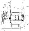
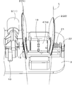
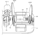
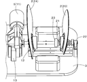
- FIGS. 5 to 7 show the rotary rotor 18 (one foot massage machine) in FIGS. 2 to 4 omitted.
- the inclined rotor 14 that rotates integrally with the rotary shaft 10 rotates.
- the inclined rotor 14 fitted to the massage member 2 on that side is also a bearing 22 provided on the left side of the base 3.
- the rotating shaft 10 and the inclined rotor 14 are rotated together as a unit.
- the conversion part 12 has a structure which engages the regulation protrusion 16 which protrudes downward from the massage member 2 with the horizontal groove body 17 (horizontal long hole).
- the inclination direction in which the inclined rotor 14 is inclined with respect to the rotating shaft 10 is set to be a relative reverse direction between the massage members 2. Therefore, when the rotating shaft 10 is rotated when the front upper edge and the rear upper edge of the massage member 2 are separated from each other, the front upper edge side of the massage member 2 gradually approaches and the front side of the massage member 2 The lower edge side is separated, and then the nipping operation is performed so that the rear upper edge side of the massage member 2 gradually approaches.
- the massage member 2 swings in a wavy manner under a condition restricted to a predetermined angle range while alternately repeating the sandwiching operation and the releasing operation described above.
- the non-moving massage member 24 (the massage member 2 provided on the inner side of the pair of massage members 2 provided on the left side, Among the pair of massage members 2 provided on the right side, the massage member 2 provided on the inner side performs a swell-like rocking motion as described above.
- the movable massage member 20 (the massage member 2 provided on the outside of the pair of massage members 2 provided on the left side, and the outside of the pair of massage members 2 provided on the right side)
- the massaging member 2) provided on the inner side of the base 3 moves along the rotation axis 10.
- the inclined rotor 14 slides around the screw screw portion 21 and moves on the screw screw portion 21 (rotation drive shaft) toward the center of the base 3. Then, the space
- the massage member 2 swings in a wavy manner under a condition restricted to a predetermined angle range while alternately repeating the above-described sandwiching operation and releasing operation.
- the massage member 2 swings in a wavy manner under a condition restricted to a predetermined angle range while alternately repeating the above-described sandwiching operation and releasing operation.
- at least one of the pair of left and right massage members 2 moves in the horizontal direction along the rotation shaft 10 by rotating the rotation shaft 10,
- By having a horizontal movement mechanism in which the interval between the massage members 2 is variable even a user having lower limbs L of various thicknesses can perform an effective massage treatment with the pair of left and right massage members 2. Become.
Landscapes
- Health & Medical Sciences (AREA)
- Dermatology (AREA)
- Epidemiology (AREA)
- Pain & Pain Management (AREA)
- Physical Education & Sports Medicine (AREA)
- Rehabilitation Therapy (AREA)
- Life Sciences & Earth Sciences (AREA)
- Animal Behavior & Ethology (AREA)
- General Health & Medical Sciences (AREA)
- Public Health (AREA)
- Veterinary Medicine (AREA)
- Massaging Devices (AREA)
Abstract
Priority Applications (4)
| Application Number | Priority Date | Filing Date | Title |
|---|---|---|---|
| HK18103003.9A HK1243623B (zh) | 2016-03-02 | 2016-04-15 | 按摩器 |
| US15/121,679 US10426693B2 (en) | 2016-03-02 | 2016-04-15 | Massage machine |
| CN201680022735.1A CN107530222B (zh) | 2016-03-02 | 2016-04-15 | 按摩器 |
| SG11201707121SA SG11201707121SA (en) | 2016-03-02 | 2016-04-15 | Massage machine |
Applications Claiming Priority (2)
| Application Number | Priority Date | Filing Date | Title |
|---|---|---|---|
| JP2016040215A JP6412517B2 (ja) | 2016-03-02 | 2016-03-02 | マッサージ機 |
| JP2016-040215 | 2016-03-02 |
Publications (1)
| Publication Number | Publication Date |
|---|---|
| WO2017149786A1 true WO2017149786A1 (fr) | 2017-09-08 |
Family
ID=59743639
Family Applications (1)
| Application Number | Title | Priority Date | Filing Date |
|---|---|---|---|
| PCT/JP2016/062054 Ceased WO2017149786A1 (fr) | 2016-03-02 | 2016-04-15 | Appareil de massage |
Country Status (6)
| Country | Link |
|---|---|
| US (1) | US10426693B2 (fr) |
| JP (1) | JP6412517B2 (fr) |
| CN (1) | CN107530222B (fr) |
| SG (1) | SG11201707121SA (fr) |
| TW (1) | TWI689301B (fr) |
| WO (1) | WO2017149786A1 (fr) |
Cited By (1)
| Publication number | Priority date | Publication date | Assignee | Title |
|---|---|---|---|---|
| JP2023017044A (ja) * | 2018-04-04 | 2023-02-02 | 大東電機工業株式会社 | マッサージ機 |
Families Citing this family (13)
| Publication number | Priority date | Publication date | Assignee | Title |
|---|---|---|---|---|
| US10765589B2 (en) | 2016-08-16 | 2020-09-08 | David S. Fleming | Therapeutic device for treatment of headache and pain |
| FR3065639B1 (fr) * | 2017-04-26 | 2021-03-05 | Lpg Systems | Tete de massage et appareil de massage mettant en œuvre une telle tete |
| JP6723560B2 (ja) * | 2017-07-24 | 2020-07-15 | 大東電機工業株式会社 | マッサージ機 |
| CN110269790A (zh) * | 2018-03-16 | 2019-09-24 | 香港中文大学 | 用于关节窝的可穿戴理疗仪 |
| JP7001270B2 (ja) * | 2018-08-29 | 2022-02-03 | 大東電機工業株式会社 | 下肢用マッサージ機 |
| JP7249005B2 (ja) * | 2018-10-18 | 2023-03-30 | ファミリーイナダ株式会社 | マッサージ機 |
| KR102221142B1 (ko) * | 2018-10-31 | 2021-02-25 | 권성범 | 발 마사지기 |
| CN110123611B (zh) * | 2019-06-18 | 2021-04-13 | 威海市中心医院 | 一种护理用腿部保健按摩仪 |
| JP7453685B2 (ja) * | 2019-12-10 | 2024-03-21 | 大東電機工業株式会社 | 椅子型マッサージ機 |
| CN114081807B (zh) * | 2021-11-03 | 2025-01-10 | 宫和健康科技(上海)有限公司 | 一种按摩机芯和按摩椅 |
| CN223542150U (zh) * | 2023-03-01 | 2025-11-14 | 郭雪斌 | 一种环绕按摩组件 |
| CN117064710A (zh) * | 2023-08-03 | 2023-11-17 | 深圳市怡然智能有限公司 | 可调宽度的揉捏驱动机构 |
| CN117323192B (zh) * | 2023-12-01 | 2024-02-13 | 四川省医学科学院·四川省人民医院 | 一种神经外科临床理疗设备 |
Citations (5)
| Publication number | Priority date | Publication date | Assignee | Title |
|---|---|---|---|---|
| JPS5752453A (en) * | 1980-09-13 | 1982-03-27 | Matsushita Electric Works Ltd | Massager |
| JP2002248142A (ja) * | 2001-02-26 | 2002-09-03 | Daito Denki Kogyo Kk | 首用マッサージ装置 |
| WO2005084604A1 (fr) * | 2004-03-10 | 2005-09-15 | Young-A Lee | Dispositif de massage de pied |
| US20060030800A1 (en) * | 2003-04-09 | 2006-02-09 | Kassel Arthur M | Massage device |
| JP2006304864A (ja) * | 2005-04-26 | 2006-11-09 | Marutaka Techno:Kk | 脚のマッサージ機 |
Family Cites Families (15)
| Publication number | Priority date | Publication date | Assignee | Title |
|---|---|---|---|---|
| US5445595A (en) * | 1994-03-30 | 1995-08-29 | Chou; Jen-Chung | Massaging machine |
| JP3940469B2 (ja) * | 1997-06-18 | 2007-07-04 | 株式会社寺西電機製作所 | マッサージ機 |
| JP3339849B2 (ja) * | 2000-04-06 | 2002-10-28 | 大東電機工業株式会社 | 下肢用マッサージ機とこのマッサージ機を用いた椅子型マッサージ装置 |
| JP2002153532A (ja) * | 2000-11-17 | 2002-05-28 | Omron Corp | マッサージ機 |
| JP3377195B2 (ja) | 2001-06-22 | 2003-02-17 | 大東電機工業株式会社 | 下肢用マッサージ機とこのマッサージ機を用いた椅子型マッサージ装置 |
| US6969361B2 (en) * | 2003-05-22 | 2005-11-29 | Wen-Hsu Hsieh | Leg massage device |
| JPWO2005023169A1 (ja) * | 2003-08-29 | 2006-11-02 | 大東電機工業株式会社 | 下肢用マッサージ装置 |
| JP4200201B2 (ja) * | 2003-09-12 | 2008-12-24 | 株式会社マルタカテクノ | マッサージ機 |
| DE602004003463T2 (de) * | 2004-02-11 | 2007-03-15 | Ciar S.P.A., Borgo Santa Maria | Gerät zum Massieren der Waden |
| US7108670B2 (en) * | 2004-09-29 | 2006-09-19 | Chien-Ming Huang | Limb massager |
| CN1778284B (zh) * | 2004-11-23 | 2010-06-23 | 光昱金属有限公司 | 气压自动调整距离按摩结构 |
| US7338458B2 (en) * | 2005-01-06 | 2008-03-04 | Wen-Hsu Hsien | Air-pressure massaging device having an automatic adjustment function |
| US20080091129A1 (en) * | 2006-10-11 | 2008-04-17 | Ko-Po Chen | Multi-function leg massaging device |
| KR100966084B1 (ko) * | 2008-02-25 | 2010-06-28 | 한정민 | 경추용 교정장치 |
| CN103622808B (zh) * | 2013-07-18 | 2015-08-26 | 厦门蒙发利科技(集团)股份有限公司 | 一种脚部按摩装置 |
-
2016
- 2016-03-02 JP JP2016040215A patent/JP6412517B2/ja active Active
- 2016-04-15 US US15/121,679 patent/US10426693B2/en active Active
- 2016-04-15 CN CN201680022735.1A patent/CN107530222B/zh active Active
- 2016-04-15 WO PCT/JP2016/062054 patent/WO2017149786A1/fr not_active Ceased
- 2016-04-15 SG SG11201707121SA patent/SG11201707121SA/en unknown
- 2016-04-27 TW TW105113022A patent/TWI689301B/zh active
Patent Citations (5)
| Publication number | Priority date | Publication date | Assignee | Title |
|---|---|---|---|---|
| JPS5752453A (en) * | 1980-09-13 | 1982-03-27 | Matsushita Electric Works Ltd | Massager |
| JP2002248142A (ja) * | 2001-02-26 | 2002-09-03 | Daito Denki Kogyo Kk | 首用マッサージ装置 |
| US20060030800A1 (en) * | 2003-04-09 | 2006-02-09 | Kassel Arthur M | Massage device |
| WO2005084604A1 (fr) * | 2004-03-10 | 2005-09-15 | Young-A Lee | Dispositif de massage de pied |
| JP2006304864A (ja) * | 2005-04-26 | 2006-11-09 | Marutaka Techno:Kk | 脚のマッサージ機 |
Cited By (2)
| Publication number | Priority date | Publication date | Assignee | Title |
|---|---|---|---|---|
| JP2023017044A (ja) * | 2018-04-04 | 2023-02-02 | 大東電機工業株式会社 | マッサージ機 |
| JP7403189B2 (ja) | 2018-04-04 | 2023-12-22 | 大東電機工業株式会社 | マッサージ機 |
Also Published As
| Publication number | Publication date |
|---|---|
| CN107530222A (zh) | 2018-01-02 |
| JP6412517B2 (ja) | 2018-10-24 |
| US10426693B2 (en) | 2019-10-01 |
| CN107530222B (zh) | 2019-10-08 |
| TWI689301B (zh) | 2020-04-01 |
| SG11201707121SA (en) | 2017-10-30 |
| HK1243623A1 (zh) | 2018-07-20 |
| US20180133095A1 (en) | 2018-05-17 |
| TW201731478A (zh) | 2017-09-16 |
| JP2017153734A (ja) | 2017-09-07 |
Similar Documents
| Publication | Publication Date | Title |
|---|---|---|
| JP6412517B2 (ja) | マッサージ機 | |
| CN1195473C (zh) | 滚轮按摩机构及内置有该按摩机构的按摩装置 | |
| JP5396366B2 (ja) | マッサージ装置 | |
| WO2020044572A1 (fr) | Dispositif de massage de membre inférieur | |
| TWI484949B (zh) | 按摩器 | |
| JP2019000159A (ja) | 下肢用マッサージ機 | |
| JP5593298B2 (ja) | マッサージ機 | |
| HK1205927A1 (en) | Massage machine | |
| CN104434478A (zh) | 按摩机 | |
| JP6642375B2 (ja) | マッサージ装置 | |
| TWI806437B (zh) | 按摩器 | |
| CN110505860B (zh) | 下肢用按摩机 | |
| HK1243623B (zh) | 按摩器 | |
| JPH11137622A (ja) | マッサージ機 | |
| JP2005080782A (ja) | 下肢用マッサージ機とこのマッサージ機を用いた椅子型マッサージ装置 | |
| JP4046064B2 (ja) | マッサージ装置およびそれを用いた椅子型マッサージ機 | |
| JP7536324B2 (ja) | マッサージ機 | |
| HK40012918A (en) | Lower limb massaging machine | |
| JPS5935217Y2 (ja) | マツサ−ジ機 | |
| JP2002153532A (ja) | マッサージ機 | |
| JP6699038B2 (ja) | 下肢用マッサージ機 | |
| CN120154508A (zh) | 按摩机 | |
| JP2016107040A (ja) | マッサージ機 | |
| HK40012918B (zh) | 下肢用按摩机 | |
| JP2000157593A (ja) | マッサージユニット |
Legal Events
| Date | Code | Title | Description |
|---|---|---|---|
| WWE | Wipo information: entry into national phase |
Ref document number: 15121679 Country of ref document: US |
|
| WWE | Wipo information: entry into national phase |
Ref document number: 11201707121S Country of ref document: SG |
|
| NENP | Non-entry into the national phase |
Ref country code: DE |
|
| 121 | Ep: the epo has been informed by wipo that ep was designated in this application |
Ref document number: 16892625 Country of ref document: EP Kind code of ref document: A1 |
|
| 122 | Ep: pct application non-entry in european phase |
Ref document number: 16892625 Country of ref document: EP Kind code of ref document: A1 |