WO2017149798A1 - Filtre d'humidification et humidificateur - Google Patents
Filtre d'humidification et humidificateur Download PDFInfo
- Publication number
- WO2017149798A1 WO2017149798A1 PCT/JP2016/072557 JP2016072557W WO2017149798A1 WO 2017149798 A1 WO2017149798 A1 WO 2017149798A1 JP 2016072557 W JP2016072557 W JP 2016072557W WO 2017149798 A1 WO2017149798 A1 WO 2017149798A1
- Authority
- WO
- WIPO (PCT)
- Prior art keywords
- humidifying filter
- filter
- humidification
- water
- holding frame
- Prior art date
- Legal status (The legal status is an assumption and is not a legal conclusion. Google has not performed a legal analysis and makes no representation as to the accuracy of the status listed.)
- Ceased
Links
Images


Classifications
-
- F—MECHANICAL ENGINEERING; LIGHTING; HEATING; WEAPONS; BLASTING
- F24—HEATING; RANGES; VENTILATING
- F24F—AIR-CONDITIONING; AIR-HUMIDIFICATION; VENTILATION; USE OF AIR CURRENTS FOR SCREENING
- F24F6/00—Air-humidification, e.g. cooling by humidification
- F24F6/02—Air-humidification, e.g. cooling by humidification by evaporation of water in the air
- F24F6/06—Air-humidification, e.g. cooling by humidification by evaporation of water in the air using moving unheated wet elements
-
- F—MECHANICAL ENGINEERING; LIGHTING; HEATING; WEAPONS; BLASTING
- F24—HEATING; RANGES; VENTILATING
- F24F—AIR-CONDITIONING; AIR-HUMIDIFICATION; VENTILATION; USE OF AIR CURRENTS FOR SCREENING
- F24F11/00—Control or safety arrangements
- F24F11/0008—Control or safety arrangements for air-humidification
-
- F—MECHANICAL ENGINEERING; LIGHTING; HEATING; WEAPONS; BLASTING
- F24—HEATING; RANGES; VENTILATING
- F24F—AIR-CONDITIONING; AIR-HUMIDIFICATION; VENTILATION; USE OF AIR CURRENTS FOR SCREENING
- F24F6/00—Air-humidification, e.g. cooling by humidification
- F24F2006/008—Air-humidifier with water reservoir
-
- F—MECHANICAL ENGINEERING; LIGHTING; HEATING; WEAPONS; BLASTING
- F24—HEATING; RANGES; VENTILATING
- F24F—AIR-CONDITIONING; AIR-HUMIDIFICATION; VENTILATION; USE OF AIR CURRENTS FOR SCREENING
- F24F6/00—Air-humidification, e.g. cooling by humidification
- F24F6/02—Air-humidification, e.g. cooling by humidification by evaporation of water in the air
- F24F6/06—Air-humidification, e.g. cooling by humidification by evaporation of water in the air using moving unheated wet elements
- F24F2006/065—Air-humidification, e.g. cooling by humidification by evaporation of water in the air using moving unheated wet elements using slowly rotating discs for evaporation
-
- F—MECHANICAL ENGINEERING; LIGHTING; HEATING; WEAPONS; BLASTING
- F24—HEATING; RANGES; VENTILATING
- F24F—AIR-CONDITIONING; AIR-HUMIDIFICATION; VENTILATION; USE OF AIR CURRENTS FOR SCREENING
- F24F2203/00—Devices or apparatus used for air treatment
- F24F2203/10—Rotary wheel
- F24F2203/1024—Rotary wheel combined with a humidifier
Definitions
- the present invention relates to a humidifying filter and a humidifier used in a humidifier.
- Patent Document 1 discloses a technique for reducing the cost required for replacement of a humidifying filter by replacing only a portion where impurities are attached without replacing the entire humidifying filter.
- JP 2009-68732 A (published on April 2, 2009)
- a general humidification filter is formed by folding a non-woven fabric into a bellows shape because it needs a certain degree of hardness in order to avoid deterioration due to shape loss and influence on the humidification amount. For this reason, there is a problem that the humidifying filter cannot be squeezed and impurities adhering to the humidifying filter cannot be sufficiently removed even by washing with water.
- the present invention has been made in view of the above problems, and an object of the present invention is to provide a humidifying filter capable of sufficiently removing impurities adhering to the humidifying filter by washing with water and a humidifier equipped with such a humidifying filter. It is to be realized.
- a humidifying filter is a humidifying filter mounted on a humidifier, and is configured by two sheet materials that are detachably bonded to each other. It is characterized in that a support body for supporting the sheet material is provided in a state where the sheet materials are bonded together.
- the impurities attached to the humidifying filter can be sufficiently removed by washing with water.
- FIG. 1 It is a schematic block diagram of the humidification filter which concerns on Embodiment 1 of this invention. It is an external appearance perspective view of the humidifier provided with the humidification filter shown in FIG. It is sectional drawing which shows schematic structure of the humidifier shown in FIG. It is a perspective view which shows the support structure of the humidification filter unit of the humidifier shown in FIG. It is a perspective view of the support frame which supports the humidification filter which concerns on Embodiment 2 of this invention, (a) is a perspective view before humidification filter installation, (b) is after a humidification filter installation. It is a schematic block diagram for demonstrating the humidification control in the humidifier which concerns on Embodiment 3 of this invention.
- Embodiment 1 Hereinafter, embodiments of the present invention will be described in detail.
- the humidifier according to the present invention includes a blower fan 2, a humidifying filter unit 3, and a water tank 4 inside a rectangular box-shaped housing 1.
- the interior of the housing 1 is divided into a rear suction chamber 1b and a front discharge chamber 1c by a partition wall 1a.
- the suction chamber 1b communicates with the outside through a large number of air inlets 15, 15... Provided in the rear panel 14 of the housing 1, and the discharge chamber 1 c is an air supply established on the top plate of the housing 1. It communicates with the outside through the mouth 16. Further, the suction chamber 1b and the discharge chamber 1c communicate with each other through an opening 1d provided in the lower portion of the partition wall 1a.
- the rear panel 14 is detachable, and a deodorizing filter 17 and a dust collecting filter 18 are laminated on the front side of the rear panel 14.
- the deodorizing filter 17 is formed by, for example, dispersing and holding activated carbon in a nonwoven fabric, and acts to adsorb and remove odorous components in the air.
- the dust collection filter 18 is a known HEPA (HighHEfficiency Particulate Air) filter, for example, and acts to collect and remove fine dust contained in the ventilation.
- HEPA HighHEfficiency Particulate Air
- the blower fan 2 includes an impeller 20 and a fan motor 21 that drives the impeller 20.
- the fan motor 21 is fixed outside the discharge chamber 1c.
- the impeller 20 is fixed to the output end of the fan motor 21 projecting into the discharge chamber 1c, and is disposed so as to face the opening 1d below the partition wall 1a.
- the impeller 20 of the blower fan 2 is rotated by driving a fan motor 21.
- the impeller 20 rotates, as indicated by white arrows in FIG. 3
- outside air is introduced into the suction chamber 1 b through the intake ports 15, 15... Provided in the rear panel 14. It flows forward in the suction chamber 1b and is sucked into the impeller 20 through the opening 1d at the lower part of the partition wall 1a.
- the direction is changed upward and led out into the discharge chamber 1c, and the air supply port at the end of the discharge chamber 1c. 16 and sent to the outside.
- the suction chamber 1b and the discharge chamber 1c inside the housing 1 constitute the above-described air flow path in which the air flow is generated according to the operation of the blower fan 2.
- the deodorizing filter 17 and the dust collecting filter 18 are located on the upstream side of the air passage as described above, and the outside air introduced into the suction chamber 1b through the intake ports 15, 15... Passes through the deodorizing filter 17.
- the odor component is removed by the above, and the air passes through the dust collection filter 18 to become clean air from which dust is removed, and is sent out through the air supply port 16 at the end of the discharge chamber 1c.
- the illustrated humidifier also functions as an air purifier due to the arrangement of the deodorizing filter 17 and the dust collecting filter 18.
- the humidification filter unit 3 and the water tank 4 are arranged between the dust collection filter 18 and the blower fan 2 so as to humidify the air flowing through the air passage as described above.
- the water tank 4 is a dish-shaped container having an open top, and is placed inside the suction chamber 1 b on the front side of the dust collection filter 18 by being fitted into a guide portion 19 provided on the bottom plate of the housing 1. As shown in FIG. 2, the water tank 4 is pulled out from one side surface of the housing 1 by sliding along the guide portion 19 together with the humidifying filter unit 3 supported on the water tank 4 as described later. It is possible.
- a wide tank receiver 40 is connected to the end of the water tank 4 on the drawer side, and a water supply tank 41 is attached to and detached from the tank receiver 40.
- the water supply tank 41 is a rectangular parallelepiped tank having a water tap 42 at one end, and is mounted on the tank receiver 40 in an inverted posture with the water tap 42 side facing downward.
- the water tap 42 incorporates a known constant water level valve.
- the constant water level valve is pushed up by a push-up protrusion 43 (see FIG. 4) standing at a corresponding position of the tank receiver 40 to be opened and accommodated in the water supply tank 41. Water is sent out to the water tank 4 and acts to store water at a constant water level inside the water tank 4.
- the humidifying filter unit 3 is configured by accommodating and holding a humidifying filter 31 inside a holding frame 30 having a hollow disk shape. That is, the holding frame 30 has a disk shape that rotates around the horizontal axis, and accommodates and holds the humidifying filter 131 therein.
- the humidifying filter 31 is composed of two detachable sheets made of a material such as a non-woven fabric that has a high water content and can be ventilated and can be washed. Details of the humidifying filter 31 will be described later.
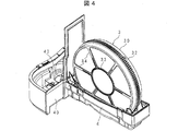
- FIG. 4 is a perspective view showing a support structure of the humidifying filter unit 3.
- FIG. 4 only the holding frame 30 is illustrated, and the illustration of the humidifying filter 31 inside the holding frame 30 is omitted.
- FIG. 4 shows only a tank receiver 40 on one side of the water tank 4, and a water supply tank 41 attached to the tank receiver 40 is not shown.
- the humidifying filter unit 3 is supported in a posture in which the humidifying filter unit 3 stands vertically on the water tank 4 by placing the holding frame 30 on the two support rollers 6 and 6 provided inside the water tank 4.
- the support rollers 6 and 6 are rollers that rotate around the axis in the front-rear direction, are distributed on both sides in the longitudinal direction on the bottom surface of the water tank 4, and are in rolling contact with the outer peripheral surface of the holding frame 30 at each position.
- the humidifying filter unit 3 supported in this way can rotate around the central axis by the rolling of the support rollers 6 and 6.
- the humidified filter unit 3 supported in this manner can be easily removed by pulling it out together with the water tank 4 from one side of the housing 1 and lifting it upward. Conversely, by inserting a part thereof into the water tank 4 and placing it on the two support rollers 6, 6, it can be easily supported in the above-described posture. It can be pushed into the interior and set at a predetermined position inside the housing 1. Such attachment / detachment of the humidifying filter unit 3 is performed for maintenance and replacement of the humidifying filter 31 housed in the holding frame 30 and further for cleaning the inside of the water tank 4.
- a ring gear portion 32 having an appropriate width in which teeth are formed over the entire circumference is integrally provided on the outer peripheral surface of the holding frame 30. As shown in FIG. 3, the ring gear portion 32 is meshed with a transmission gear 51 of the drive unit 5 disposed above the holding frame 30.
- the drive unit 5 includes a transmission gear 51 and a drive gear 52 attached to one surface of the base 50 and a drive motor 53 attached to the other surface of the base 50, and a plurality of fixing screws (see FIG. (Not shown) is fixed at an appropriate position of the partition wall 1a inside the housing 1.
- the drive gear 52 is fitted to the output shaft of the drive motor 53, and the rotation of the drive motor 53 is transmitted to the transmission gear 51 via the drive gear 52, and the transmission gear 51 rotates. .
- the transmission gear 51 of the drive unit 5 and the ring gear portion 32 of the holding frame 30 mesh as shown in FIG. 3 when the humidifying filter unit 3 is set at the predetermined position described above. By this meshing, the humidifying filter unit 3 is supported at three points in different circumferential directions by the two support rollers 6 and 6 inside the water tank 4 and the transmission gear 51 of the drive unit 5.
- the humidifying filter unit 3 supported in this manner is positioned so as to face the front side of the dust collection filter 18 and the rear side of the blower fan 2 inside the suction chamber 1 b, and the drive motor 53.
- the rotation of the drive gear 52 is transmitted to the holding frame 30 via the transmission gear 51 and the ring gear portion 32, and the humidifying filter unit 3 rotates around the central axis while maintaining the support position shown in FIG.
- a circular support ring 33 is formed at the center of the rear surface of the holding frame 30 shown in FIG. 4 (the surface facing the dust collection filter 18) and the front surface opposite to the rear surface.
- a plurality of (six in the figure) support ribs 34, 34... Communicating with the outer peripheral part are provided, respectively, and an arcuate closing part 35 is provided so as to close one part in the vicinity of the outer peripheral part.
- the accommodation space of the humidifying filter 31 inside the holding frame 30 has a cross-sectional shape excluding the arcuate closing portion 35, that is, a cross-sectional shape in which a circular part is notched into an arcuate shape.
- the humidified filter 31 is held in a state of being supported from both the front and rear sides by the support ring 33 and the support ribs 34, 34.
- the water tank 4 stores water at a constant water level as described above.
- the lower part of the holding frame 30 that rotates as described above is immersed in the stored water of the water tank 4, and the stored water enters the holding frame 30 through the front and rear openings and is accommodated and held in the holding frame 30. Water is absorbed by the humidifying filter 31.
- the air flow described above is generated in the suction chamber 1b and the discharge chamber 1c in the housing 1, and the air is supplied to the holding frame 30 of the humidifying filter unit 3. Is introduced through the opening on the front surface, and is passed through the humidification filter 31 and sent out through the opening on the rear surface.
- the humidifying filter unit 3 rotates, and as described above, the water stored in the water tank 4 is absorbed by the humidifying filter 31 in the holding frame 30 and lifted by the rotation of the holding frame 30. It spreads throughout the humidifying filter 31.
- the air flowing as described above comes into contact with the humidifying filter 31 containing water, becomes humid air containing vaporized water, is sent out through the air supply port 16 at the end of the discharge chamber 1c, and passes through the room where the humidifier is installed. Humidify.
- the humidification filter 31 is mounted on a humidifier and is composed of two sheet materials 11 and 12 as shown in FIG.
- Each of the sheet materials 11 and 12 is made of a material (rayon, PET, etc.) that has high water content and can be ventilated, such as a non-woven fabric, and can be squeezed and washed.
- the attachment and detachment of the sheet materials 11 and 12 is performed by attachment / detachment members 13a and 13b provided at the respective peripheral portions.
- These detachable members 13a and 13b may be any members as long as they can attach and detach the sheet materials 11 and 12 with one touch such as Velcro (registered trademark) and hooks.
- Velcro registered trademark
- the sheet materials 11 and 12 are pasted together by the detachable members 13a and 13b with the back surfaces facing each other. Since the laminated sheet materials 11 and 12 are difficult to be self-supporting because the materials are soft, they are supported by being held in a holding frame 30 that is a support.
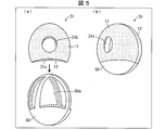
- the sheet material 12 has a circular shape as shown in FIG. 1A, but the sheet material 11 has a structure in which an end portion 11a is notched. Thereby, when the two sheet materials 11 and 12 are bonded together, as shown in FIG. 1B, the sheet material 12 is partially exposed by the end 11a of the sheet material 11 on the sheet material 11 side. It becomes.
- the humidifying filter 31 configured in this manner has a structure in which two sheet materials 11 and 12 are stacked, but since there is no overlapping portion between the sheet material 11 and the sheet material 12 at one end 31a, The sheet material 11 and the sheet material 12 can be easily peeled off by inserting a finger into the one end 31a.
- sheet materials 11 and 12 may have different structures.
- the humidifying filter 31 can be easily separated into the sheet materials 11 and 12 after being removed from the apparatus, and each of the humidifying filters 31 can be rinsed and washed, so that impurities attached to the sheet materials 11 and 12 can be easily removed. it can. That is, the user can easily clean the humidifying filter 31.
- the sheet materials 11 and 12 can be easily attached / detached by attaching / detaching members 13a and 13b such as a magic tape and a hook, the front and back surfaces can be sufficiently washed.
- the sheet materials 11 and 12 are supported by the holding frame 30 as a support in a state where they are bonded together, the sheet materials 11 and 12 do not require much thickness and strength. That is, it is possible to use a soft material that can be washed by squeezing for the sheet materials 11 and 12. Thereby, the impurities adhering to the humidification filter 31 can be sufficiently removed only by washing with water by washing the sheet materials 11 and 12.
- the humidifying filter 31 has the end portion 11a of the sheet material 11 cut away, so that it is easy to determine which side is to be upwinded when the sheet materials 11 and 12 are bonded together. Judgment can be made.
- the sheet materials 11 and 12 are detachably provided by detachable members 13a and 13b such as velcro tapes and hooks provided at predetermined positions, the sheet materials 11 and 12 can be easily positioned. can do.
- the sheet materials 11 and 12 constituting the humidifying filter 31 may have different water absorption amounts. If it is made of the same material, the amount of water absorption with the sheet material 12 can be made different by cutting out the end portion 11a of the sheet material 11 as shown in FIG.
- the sheet materials 11 and 12 may have the same shape (surface area), and neither of them may have a notch structure. In this case, the material of the sheet materials 11 and 12 may be made different to make the water absorption amount different.
- the sheet materials 11 and 12 have the same shape (surface area) and are not cut out, the sheet materials 11 and 12 are made of the same material, have different thicknesses, and different amounts of water absorption. Also good.
- the opening ratio of the sheet material 11 is made smaller than the opening ratio of the sheet material 12.
- the aperture ratio indicates the roughness of the nonwoven fabric constituting the sheet material.
- a large aperture ratio means that the eyes are rough, and a small aperture ratio means that the eyes are fine. Therefore, as described above, by making the opening ratios of the sheet materials 11 and 12 different, the humidifying filter 31 collects a large amount of dust not only with the humidifying function but also with the upstream sheet material 12, and the sheet material.
- the dust collecting function of collecting dust contained in the air that has passed through the sheet 12 with the sheet material 11 is also achieved.
- the humidifying filter 31 is held by the holding frame 30 (support) in a state where the sheet materials 11 and 12 are bonded together.
- the holding frame 30 has a hollow disk shape, and accommodates and holds the humidifying filter 31 therein. For this reason, in order to clean the humidification filter 31, it is necessary to take out the humidification filter from the inside of the holding frame 30.
- peripheral edges of the sheet materials 11 and 12 may be bonded together by ultrasonic welding or the like. In that case, the sheet materials 11 and 12 become hollow.
- the central portions of the sheet materials 11 and 12 may also be bonded together by ultrasonic welding or the like. Further, when the sheet materials 11 and 12 have a notch structure, the notch portion may be bonded by ultrasonic welding or the like.
- Embodiment 2 the structure of the humidifying filter 31 is used, and the humidifying filter 31 is not housed inside the holding frame 30 but is inserted into the humidifying filter 31.
- the structure that promotes the autonomy of the humidifying filter 31 will be described.
- the humidifying filter 31 includes a support body 60 that supports the sheet materials 11 and 12 in a state where the two sheet materials 11 and 12 are bonded together. I have. That is, as shown in FIG. 5B, the two sheet materials 11 and 12 cover the support 60 in a bonded state.
- the support 60 has a three-dimensional frame structure, and the interior 60a has a hollow structure. Thereby, since the surface area of the said humidification filter 31 can be expanded by covering the humidification filter 31 so that the support body 60 may be covered, a humidification effect can be heightened.
- the humidification filter 31 since the humidification filter 31 is in a state of covering the support body 60, it can be easily detached from the support body 60.
- the opening ratio of the sheet material 11 is preferably smaller than the opening ratio of the sheet material 12.
- the structure of the support 60 is not limited to the shape shown in FIG. 5A, and may be a shape that allows the humidifying filter 31 to be three-dimensionally maintained when the humidifying filter 31 is covered. Any shape may be used.
- the inside 60a of the support body 60 is preferably a hollow structure so that air is allowed to pass through in order to vaporize water contained in the humidified filter 31 covered, but it may not be a hollow structure.
- the inside 60a of the support body 60 may have a hollow structure, and the rotation center 31b of the humidified filter 31 covered may be opened. Using this opening, the humidifying filter 31 is rotated together with the support body 60.
- a humidifier having the same structure as in the first and second embodiments is used except that the humidifying filter 131 is used.
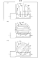
- the humidifying filter 131 absorbs water along the fold line 131a, the amount of water absorption varies depending on the angle formed between the direction in which the fold line 131a extends and the direction parallel to the water surface of the stored water in the water tank 4.
- the angle formed between the direction in which the folding line 131a extends and the direction parallel to the water surface of the stored water in the water tank 4 is 90 ° in FIG. 6A, 180 ° in FIG. 6B, and FIG. (C) shows 45 °.
- FIG. 7 is a graph showing a change in the humidification amount with time when the rotation of the humidification filter 131 is stopped at the angle shown in FIG.
- the air volume applied to the humidifying filter 131 is constant at 6.8 cm.
- the amount of humidification is the largest when the angle formed by the direction in which the folding line 131a extends and the direction parallel to the water surface of the stored water in the water tank 4 is 90 °, and the most humidified when the angle is 180 °. You can see that the amount is small.
- the humidification filter 131 is adjusted by adjusting the angle formed by the direction in which the folding line 131a extends and the direction parallel to the water surface of the stored water in the water tank 4 (hereinafter referred to as the humidification control angle). It can be seen that the amount can be controlled.
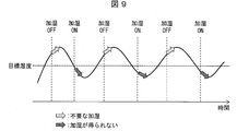
- FIG. 8 is a graph showing the humidification control of the present embodiment
- FIG. 9 is a graph showing the conventional humidification control for comparison with FIG.
- the humidification amount is controlled only by adjusting the rotation angle of the humidification filter 131, the amount of wind applied to the humidification filter 131 may be constant. Since it is not necessary to increase or decrease more than necessary, it is possible to reduce noise caused by the fan for blowing air. For this reason, the noise at the time of the humidification driving
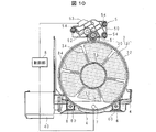
- FIG. 10 is a diagram illustrating a humidifying filter unit support structure for realizing humidification control of the humidifier according to the present embodiment.
- the humidifier includes a position detector 7 that detects that the humidifying filter 131 is at a predetermined rotational position (the rotational positions shown in FIGS. 6A to 6C). .
- the position detector 7 includes a detector provided on the closing portion 35 of the holding frame 30 at an appropriate distance from the center to one side in the circumferential direction. It is configured to output a detection signal when it is in the uppermost lower position.
- the position detector 7 can be configured by a combination of a magnet as a detector and a proximity switch, for example.
- a control unit 8 indicated by blocks in FIG. 10 is a computer including a CPU, a ROM, and a RAM, and gives an operation command to the drive unit 5 in accordance with a driving operation by a user, and performs an operation for driving and controlling them.
- the humidifying filter unit 3 rotates, and as described above, the water stored in the water tank 4 is absorbed by the humidifying filter 131 in the holding frame 30 and lifted by the rotation of the holding frame 30. It spreads throughout the humidifying filter 131. Accordingly, the air flowing as described above comes into contact with the humidifying filter 131 containing water, becomes humid air containing vaporized water, is sent out of the apparatus, and humidifies the room where the humidifier is installed. That is, the air flowing from one surface to the other surface of the holding frame 30 is brought into contact with the humidifying filter 131 that rotates together with the holding frame 30 including the water stored in the water tank 4, and humid air containing vaporized moisture is brought into the other surface side. To humidify the room where the humidifier is installed.
- the angle formed by the direction of the fold line 131a of the humidifying filter 131 and the direction parallel to the water surface L of the water stored in the aquarium is any one of (a) to (c) in FIG.
- a desired humidification amount can be obtained by stopping the rotation of the humidification filter unit 3.
- the rotation angle may be controlled not only by the control using the position detector 7 but also by the rotation time as long as it is a method for controlling to an appropriate amount of humidification, or by another method. Good.
- the control unit 8 refers to the detection signal of the position detector 7 and stops driving the drive unit 5 at the timing when the detection signal is input.
- the humidification filter unit 3 stops in the rotation position shown in FIG.
- This rotational position is the position where the detector provided in the closing portion 35 of the holding frame 30 as described above is at the lowest position on the rotational circumference of the holding frame 30, and the humidifying filter unit 3 is as shown in FIG.
- Most of the strings of the bow-shaped closing portion 35 are above the water level (inner water level L) of the stored water in the water tank 4 and stop in a posture inclined with respect to the water surface.
- the humidifying filter 131 accommodated in the holding frame 30 has a fold line substantially parallel to the string of the arcuate closing portion 35, and when the humidifying filter unit 3 stops, the humidifying filter A fold line 131a which is a fold line of 131 is also inclined with respect to the water surface of the stored water, that is, the horizontal direction.
- Embodiment 4 below describes a configuration in which the humidifying filter does not come into contact with the stored water when the humidifying operation is not performed in the humidifier.
- FIG. 11 shows a schematic configuration of the humidifying filter, (a) shows the humidifying filter 131 used in the third embodiment, and (b) shows the humidifying filter 231 of the present embodiment.
- the humidifying filter 131 has the center of the circle as the center of rotation.
- the humidifying filter 131 is humidified as shown in FIG. 11B.
- the filter 231 has a position shifted from the center of the circle as the center of rotation.
- the rotation center is such that the portion with the shortest distance from the rotation center to the end of the humidification filter 231 faces the water surface of the stored water, and the humidification filter 231 is It is formed in a position that does not immerse in the stored water.
- the string of the closing portion 35 is stopped when the holding frame 30 is stopped, as shown in FIG. If a part of the humidifying filter 131 is below the water level of the stored water, the humidifying filter 131 will not be immersed in the stored water, but if the retaining frame 30 is not formed with the closing portion 35, the humidifying filter 131 will be used. 131 is immersed in the stored water. In that case, a part of the humidifying filter 131 is cut so that the humidifying filter 131 is not immersed in the stored water after the rotation is stopped.
- the rotation center is a position shifted from the center of the circle as in the humidifying filter 231 in FIG. If the rotation of the humidifying filter 231 is stopped so that the short part is at the bottom, the humidifying filter 231 is not immersed in the stored water.
- the ring gear portion 32 formed on the outer peripheral surface of the holding frame 30 is rotated by meshing with the drive gear 52 (FIG. 10) of the drive unit 5.
- the ring gear portion 132 is formed around the center of rotation instead of the outer peripheral surface of the holding frame 30, and meshed with the drive gear 52 (FIG. 10) of the drive unit 5. It is rotated by doing.
- the humidifying filter can be produced more simply than cutting a part of the humidifying filter.
- the humidification filter 231 may have an elliptical shape instead of a circular shape. Good.
- the humidifying filter according to the first aspect of the present invention is a humidifying filter 31 mounted on a humidifier, and is composed of two sheet materials 11 and 12 that are detachably bonded to each other. , 12 are attached to each other, and a support body (holding frame 30, support body 60) for supporting the sheet materials 11, 12 is provided.
- the humidifying filter since the humidifying filter has a structure in which two sheet materials are detachably bonded, it is difficult to make the sheet material self-supporting unless the sheet material has a certain thickness or strength. Thus, the sheet material does not require much thickness and strength. That is, it is possible to use a soft material that can be washed in the sheet material. Thereby, by washing the sheet material, impurities adhering to the humidifying filter can be sufficiently removed only by washing with water.
- the two sheet materials 11 and 12 may cover the support 60 in a state of being bonded.
- the humidifying filter since the humidifying filter covers the support, the humidifying filter can be easily detached from the support 60.
- the support 60 preferably has a three-dimensional frame structure.
- the humidifying performance can be improved.
- the humidifying filter according to aspect 4 of the present invention is the humidifying filter according to any one of the aspects 1 to 3, wherein the end portion 11a of at least one of the two sheet materials 11 and 12 is notched. Preferably it is.
- the humidifier according to aspect 5 of the present invention includes a humidifying filter 131 formed by folding a sheet material into a bellows shape, and a disc-shaped holding frame 30 that houses and holds the humidifying filter 131 and rotates around a horizontal axis.
- the water tank 4 is arranged so that the lower part of the holding frame 30 is immersed, and the air flowing from one surface to the other surface of the holding frame 30 is rotated together with the holding frame 30 including the water stored in the water tank 4.
- a humidification control unit (control unit 8) that controls the amount of humidification by adjusting an angle formed with a direction parallel to the head is characterized.
- the humidifying filter is made of a sheet material folded in a bellows shape
- the amount of water absorption of the humidifying filter depends on the angle formed by the direction of the fold line of the humidifying filter and the direction parallel to the water surface of the stored water. Change.
- the humidification amount can be controlled by adjusting the angle between the direction of the fold line of the humidification filter and the direction parallel to the water surface of the water stored in the water tank by the humidification control unit.
- the humidification control unit (control unit 8) may control the humidification amount with a constant air volume of the ventilation.
- the air volume for ventilation can be made constant during humidification control, the number of rotations of the ventilation fan can be made constant. Thereby, increase / decrease in power consumption and noise resulting from a change in the rotation speed of the blower fan can be reduced.
- the rotation center of the humidifying filter 231 may be a position shifted from the center of the circle.
- the humidifying filter 231 when the rotation of the humidifying filter 231 is stopped, the humidifying filter 231 can be prevented from being immersed in the stored water.
- the rotation center of the humidification filter 231 has a distance from the rotation center to the end of the humidification filter 231 when the rotation of the humidification filter 231 is stopped.
- the shortest part may be formed in the position which opposes the water surface of stored water, and the said humidification filter 231 is not immersed in stored water.
- the humidifying filter 231 when the rotation of the humidifying filter 231 is stopped, the humidifying filter 231 can be reliably prevented from being immersed in the stored water.
Landscapes
- Engineering & Computer Science (AREA)
- Chemical & Material Sciences (AREA)
- Combustion & Propulsion (AREA)
- Mechanical Engineering (AREA)
- General Engineering & Computer Science (AREA)
- Air Humidification (AREA)
- Filtering Of Dispersed Particles In Gases (AREA)
Abstract
Priority Applications (5)
| Application Number | Priority Date | Filing Date | Title |
|---|---|---|---|
| SG11201801273YA SG11201801273YA (en) | 2016-02-29 | 2016-08-01 | Humidification filter and humidifier |
| CN201680046476.6A CN108700317A (zh) | 2016-02-29 | 2016-08-01 | 加湿过滤器以及加湿器 |
| KR1020187003489A KR20180026525A (ko) | 2016-02-29 | 2016-08-01 | 가습 필터 및 가습기 |
| EP16892637.6A EP3425293A4 (fr) | 2016-02-29 | 2016-08-01 | Filtre d'humidification et humidificateur |
| PH12018500337A PH12018500337A1 (en) | 2016-02-29 | 2018-02-14 | Humidification filter and humidifier |
Applications Claiming Priority (2)
| Application Number | Priority Date | Filing Date | Title |
|---|---|---|---|
| JP2016-037795 | 2016-02-29 | ||
| JP2016037795A JP6699963B2 (ja) | 2016-02-29 | 2016-02-29 | 加湿機 |
Publications (1)
| Publication Number | Publication Date |
|---|---|
| WO2017149798A1 true WO2017149798A1 (fr) | 2017-09-08 |
Family
ID=59743623
Family Applications (1)
| Application Number | Title | Priority Date | Filing Date |
|---|---|---|---|
| PCT/JP2016/072557 Ceased WO2017149798A1 (fr) | 2016-02-29 | 2016-08-01 | Filtre d'humidification et humidificateur |
Country Status (7)
| Country | Link |
|---|---|
| EP (1) | EP3425293A4 (fr) |
| JP (1) | JP6699963B2 (fr) |
| KR (1) | KR20180026525A (fr) |
| CN (1) | CN108700317A (fr) |
| PH (1) | PH12018500337A1 (fr) |
| SG (1) | SG11201801273YA (fr) |
| WO (1) | WO2017149798A1 (fr) |
Cited By (3)
| Publication number | Priority date | Publication date | Assignee | Title |
|---|---|---|---|---|
| JP2021183887A (ja) * | 2020-05-22 | 2021-12-02 | 東プレ株式会社 | 加湿エレメント |
| US20220082274A1 (en) * | 2019-01-03 | 2022-03-17 | Woongjin Coway Co., Ltd. | Humidifier |
| US20220243934A1 (en) * | 2019-06-17 | 2022-08-04 | Coway Co., Ltd. | Air humidification and purification device |
Families Citing this family (7)
| Publication number | Priority date | Publication date | Assignee | Title |
|---|---|---|---|---|
| JP7250608B2 (ja) * | 2019-05-07 | 2023-04-03 | シャープ株式会社 | 空気調和機 |
| JP7252867B2 (ja) | 2019-09-13 | 2023-04-05 | シャープ株式会社 | 空気調和機 |
| KR102291123B1 (ko) | 2020-03-03 | 2021-08-17 | 건국대학교 산학협력단 | 발포 폴리스티렌을 이용한 부정형 미세플라스틱 제조장치 및 방법 |
| CN112665023A (zh) * | 2020-05-11 | 2021-04-16 | 青岛海尔空调器有限总公司 | 空调的控制方法、装置、设备及存储介质 |
| JP2023167023A (ja) * | 2022-05-11 | 2023-11-24 | シャープ株式会社 | 加湿装置 |
| CN115978674B (zh) * | 2022-12-30 | 2024-10-18 | 广东美的环境电器制造有限公司 | 加湿器的控制方法、装置、加湿器及电子设备 |
| JP2025077766A (ja) * | 2023-11-07 | 2025-05-19 | ダイキン工業株式会社 | 加湿装置 |
Citations (7)
| Publication number | Priority date | Publication date | Assignee | Title |
|---|---|---|---|---|
| JPS61186739A (ja) * | 1985-02-14 | 1986-08-20 | Mitsubishi Electric Corp | 加湿素子 |
| US5595690A (en) * | 1995-12-11 | 1997-01-21 | Hamilton Standard | Method for improving water transport and reducing shrinkage stress in membrane humidifying devices and membrane humidifying devices |
| JP2001174008A (ja) * | 1999-12-15 | 2001-06-29 | Japan Gore Tex Inc | 加湿シート |
| JP2009068732A (ja) | 2007-09-11 | 2009-04-02 | Daikin Ind Ltd | 加湿機 |
| JP2012117770A (ja) * | 2010-12-02 | 2012-06-21 | Panasonic Corp | 加湿空気清浄機 |
| JP2013204869A (ja) * | 2012-03-27 | 2013-10-07 | Fujitsu General Ltd | 加湿装置 |
| JP2014070859A (ja) * | 2012-10-01 | 2014-04-21 | Sharp Corp | 送風機 |
Family Cites Families (10)
| Publication number | Priority date | Publication date | Assignee | Title |
|---|---|---|---|---|
| JPS5510947U (fr) * | 1978-07-06 | 1980-01-24 | ||
| US5690710A (en) * | 1996-08-13 | 1997-11-25 | Stephan; Paul F. | Self-cleaning filter |
| JP2002066225A (ja) * | 2000-08-29 | 2002-03-05 | Hokuyo Paper Co Ltd | ハニカム構造フィルター |
| CN101680672B (zh) * | 2007-05-21 | 2013-01-02 | 松下电器产业株式会社 | 加湿装置及带加湿功能的空气净化机 |
| KR20120001519A (ko) * | 2010-06-29 | 2012-01-04 | 웅진코웨이주식회사 | 가습필터 및 가습필터를 가진 가습장치 |
| JP5598300B2 (ja) * | 2010-12-10 | 2014-10-01 | パナソニック株式会社 | 加湿フィルタユニット |
| JP5503683B2 (ja) * | 2012-04-20 | 2014-05-28 | トーシンケミテック株式会社 | 加湿フィルタ |
| CN102679519B (zh) * | 2012-06-18 | 2017-10-10 | 海尔集团公司 | 一种加湿水轮及空气净化加湿器 |
| CN203401833U (zh) * | 2013-08-06 | 2014-01-22 | 林清文 | 促销抽奖卡 |
| JP2015132404A (ja) * | 2014-01-10 | 2015-07-23 | ダイキン工業株式会社 | 加湿機 |
-
2016
- 2016-02-29 JP JP2016037795A patent/JP6699963B2/ja active Active
- 2016-08-01 CN CN201680046476.6A patent/CN108700317A/zh active Pending
- 2016-08-01 WO PCT/JP2016/072557 patent/WO2017149798A1/fr not_active Ceased
- 2016-08-01 EP EP16892637.6A patent/EP3425293A4/fr not_active Withdrawn
- 2016-08-01 KR KR1020187003489A patent/KR20180026525A/ko not_active Ceased
- 2016-08-01 SG SG11201801273YA patent/SG11201801273YA/en unknown
-
2018
- 2018-02-14 PH PH12018500337A patent/PH12018500337A1/en unknown
Patent Citations (7)
| Publication number | Priority date | Publication date | Assignee | Title |
|---|---|---|---|---|
| JPS61186739A (ja) * | 1985-02-14 | 1986-08-20 | Mitsubishi Electric Corp | 加湿素子 |
| US5595690A (en) * | 1995-12-11 | 1997-01-21 | Hamilton Standard | Method for improving water transport and reducing shrinkage stress in membrane humidifying devices and membrane humidifying devices |
| JP2001174008A (ja) * | 1999-12-15 | 2001-06-29 | Japan Gore Tex Inc | 加湿シート |
| JP2009068732A (ja) | 2007-09-11 | 2009-04-02 | Daikin Ind Ltd | 加湿機 |
| JP2012117770A (ja) * | 2010-12-02 | 2012-06-21 | Panasonic Corp | 加湿空気清浄機 |
| JP2013204869A (ja) * | 2012-03-27 | 2013-10-07 | Fujitsu General Ltd | 加湿装置 |
| JP2014070859A (ja) * | 2012-10-01 | 2014-04-21 | Sharp Corp | 送風機 |
Non-Patent Citations (1)
| Title |
|---|
| See also references of EP3425293A4 |
Cited By (5)
| Publication number | Priority date | Publication date | Assignee | Title |
|---|---|---|---|---|
| US20220082274A1 (en) * | 2019-01-03 | 2022-03-17 | Woongjin Coway Co., Ltd. | Humidifier |
| US11976845B2 (en) * | 2019-01-03 | 2024-05-07 | Coway Co., Ltd. | Humidifier |
| US20220243934A1 (en) * | 2019-06-17 | 2022-08-04 | Coway Co., Ltd. | Air humidification and purification device |
| US12013150B2 (en) * | 2019-06-17 | 2024-06-18 | Coway Co., Ltd. | Air humidification and purification device |
| JP2021183887A (ja) * | 2020-05-22 | 2021-12-02 | 東プレ株式会社 | 加湿エレメント |
Also Published As
| Publication number | Publication date |
|---|---|
| KR20180026525A (ko) | 2018-03-12 |
| SG11201801273YA (en) | 2018-09-27 |
| PH12018500337A1 (en) | 2018-08-20 |
| JP6699963B2 (ja) | 2020-05-27 |
| JP2017155976A (ja) | 2017-09-07 |
| EP3425293A4 (fr) | 2019-06-26 |
| CN108700317A (zh) | 2018-10-23 |
| EP3425293A1 (fr) | 2019-01-09 |
Similar Documents
| Publication | Publication Date | Title |
|---|---|---|
| WO2017149798A1 (fr) | Filtre d'humidification et humidificateur | |
| JP5836549B2 (ja) | 空気清浄機及び空気清浄機の使用方法 | |
| JP5586345B2 (ja) | 加湿機 | |
| JP5832214B2 (ja) | 加湿装置 | |
| JP5953196B2 (ja) | 加湿装置 | |
| JP5808996B2 (ja) | 空気清浄機及び空気清浄機の使用方法 | |
| JP2016211849A (ja) | 加湿装置及び空気清浄機 | |
| JP5861990B2 (ja) | 空気調和機 | |
| JP2011122788A (ja) | 加湿装置及び空気清浄機 | |
| JP2014070859A (ja) | 送風機 | |
| JP2011047592A (ja) | 送風装置及び空気清浄機 | |
| JP5785635B2 (ja) | 加湿装置及び空気清浄機 | |
| JP5261610B2 (ja) | 加湿装置及び空気清浄機 | |
| JP6004554B2 (ja) | 加湿装置及び空気清浄機 | |
| JP5501505B2 (ja) | 加湿装置及び空気清浄機 | |
| JP5690997B2 (ja) | 加湿空気清浄機 | |
| JP5398496B2 (ja) | 加湿装置 | |
| JP2011052877A (ja) | 加湿機 | |
| JP6277293B2 (ja) | 加湿装置 | |
| JP6081639B2 (ja) | 加湿装置 | |
| JP6149954B2 (ja) | 空気調和機 | |
| JP7668543B2 (ja) | 空気調和装置 | |
| JP2016128749A5 (fr) | ||
| JP6081010B2 (ja) | 加湿装置 | |
| JP2015145779A (ja) | 空気調和機 |
Legal Events
| Date | Code | Title | Description |
|---|---|---|---|
| ENP | Entry into the national phase |
Ref document number: 20187003489 Country of ref document: KR Kind code of ref document: A |
|
| WWE | Wipo information: entry into national phase |
Ref document number: 12018500337 Country of ref document: PH |
|
| WWE | Wipo information: entry into national phase |
Ref document number: 11201801273Y Country of ref document: SG |
|
| NENP | Non-entry into the national phase |
Ref country code: DE |
|
| 121 | Ep: the epo has been informed by wipo that ep was designated in this application |
Ref document number: 16892637 Country of ref document: EP Kind code of ref document: A1 |