WO2017149875A1 - Dispositif de commande de capture d'image, dispositif de capture d'image et procédé de commande de capture d'image - Google Patents
Dispositif de commande de capture d'image, dispositif de capture d'image et procédé de commande de capture d'image Download PDFInfo
- Publication number
- WO2017149875A1 WO2017149875A1 PCT/JP2016/085927 JP2016085927W WO2017149875A1 WO 2017149875 A1 WO2017149875 A1 WO 2017149875A1 JP 2016085927 W JP2016085927 W JP 2016085927W WO 2017149875 A1 WO2017149875 A1 WO 2017149875A1
- Authority
- WO
- WIPO (PCT)
- Prior art keywords
- imaging
- field
- view
- image
- pixel
- Prior art date
- Legal status (The legal status is an assumption and is not a legal conclusion. Google has not performed a legal analysis and makes no representation as to the accuracy of the status listed.)
- Ceased
Links
Images









Classifications
-
- H—ELECTRICITY
- H04—ELECTRIC COMMUNICATION TECHNIQUE
- H04N—PICTORIAL COMMUNICATION, e.g. TELEVISION
- H04N23/00—Cameras or camera modules comprising electronic image sensors; Control thereof
- H04N23/60—Control of cameras or camera modules
- H04N23/698—Control of cameras or camera modules for achieving an enlarged field of view, e.g. panoramic image capture
-
- H—ELECTRICITY
- H04—ELECTRIC COMMUNICATION TECHNIQUE
- H04N—PICTORIAL COMMUNICATION, e.g. TELEVISION
- H04N13/00—Stereoscopic video systems; Multi-view video systems; Details thereof
- H04N13/20—Image signal generators
- H04N13/204—Image signal generators using stereoscopic image cameras
- H04N13/207—Image signal generators using stereoscopic image cameras using a single two-dimensional [2D] image sensor
- H04N13/211—Image signal generators using stereoscopic image cameras using a single two-dimensional [2D] image sensor using temporal multiplexing
-
- G—PHYSICS
- G03—PHOTOGRAPHY; CINEMATOGRAPHY; ANALOGOUS TECHNIQUES USING WAVES OTHER THAN OPTICAL WAVES; ELECTROGRAPHY; HOLOGRAPHY
- G03B—APPARATUS OR ARRANGEMENTS FOR TAKING PHOTOGRAPHS OR FOR PROJECTING OR VIEWING THEM; APPARATUS OR ARRANGEMENTS EMPLOYING ANALOGOUS TECHNIQUES USING WAVES OTHER THAN OPTICAL WAVES; ACCESSORIES THEREFOR
- G03B15/00—Special procedures for taking photographs; Apparatus therefor
-
- G—PHYSICS
- G03—PHOTOGRAPHY; CINEMATOGRAPHY; ANALOGOUS TECHNIQUES USING WAVES OTHER THAN OPTICAL WAVES; ELECTROGRAPHY; HOLOGRAPHY
- G03B—APPARATUS OR ARRANGEMENTS FOR TAKING PHOTOGRAPHS OR FOR PROJECTING OR VIEWING THEM; APPARATUS OR ARRANGEMENTS EMPLOYING ANALOGOUS TECHNIQUES USING WAVES OTHER THAN OPTICAL WAVES; ACCESSORIES THEREFOR
- G03B37/00—Panoramic or wide-screen photography; Photographing extended surfaces, e.g. for surveying; Photographing internal surfaces, e.g. of pipe
- G03B37/04—Panoramic or wide-screen photography; Photographing extended surfaces, e.g. for surveying; Photographing internal surfaces, e.g. of pipe with cameras or projectors providing touching or overlapping fields of view
-
- H—ELECTRICITY
- H04—ELECTRIC COMMUNICATION TECHNIQUE
- H04N—PICTORIAL COMMUNICATION, e.g. TELEVISION
- H04N23/00—Cameras or camera modules comprising electronic image sensors; Control thereof
- H04N23/60—Control of cameras or camera modules
- H04N23/67—Focus control based on electronic image sensor signals
-
- H—ELECTRICITY
- H04—ELECTRIC COMMUNICATION TECHNIQUE
- H04N—PICTORIAL COMMUNICATION, e.g. TELEVISION
- H04N7/00—Television systems
- H04N7/14—Systems for two-way working
- H04N7/141—Systems for two-way working between two video terminals, e.g. videophone
- H04N7/142—Constructional details of the terminal equipment, e.g. arrangements of the camera and the display
-
- H—ELECTRICITY
- H04—ELECTRIC COMMUNICATION TECHNIQUE
- H04N—PICTORIAL COMMUNICATION, e.g. TELEVISION
- H04N13/00—Stereoscopic video systems; Multi-view video systems; Details thereof
- H04N2013/0074—Stereoscopic image analysis
- H04N2013/0081—Depth or disparity estimation from stereoscopic image signals
Definitions
- the present disclosure relates to an imaging control device, an imaging device, and an imaging control method.
- Patent Document 1 discloses an example of a technique for generating an all-sky image by stitching (bonding) images from a plurality of cameras.
- the timing of reading pixel values by each camera module of the all-sky camera may differ depending on the pixel position.
- the read timing of pixel values may be different between the first pixel and the last pixel of one image sensor. This difference causes a shift in the imaging timing of the overlapping portion of the visual field between the camera modules that respectively capture the partially overlapping visual fields. This deviation is referred to as phase deviation in this specification.
- phase deviation When a fast-moving subject is imaged by an all-sky camera, the appearance of the subject does not match between adjacent camera modules due to such a phase shift, and the captured images from these camera modules are processed in an integrated manner Can be difficult to do. The same applies when imaging is performed while moving the camera quickly.
- the technology according to the present disclosure aims to eliminate or reduce inconvenience caused by phase shift in such an all-sky camera (or an apparatus that integrally processes captured images from at least a plurality of camera modules).
- the first image signal generated by imaging the first field of view in the first imaging unit and the second field of view that partially overlaps the first field of view in the second imaging unit.
- the phase of the first image signal corresponding to the overlapping portion of the first field of view and the second field of view, and the imaging timing of at least one of the second image signals generated by imaging
- An imaging control device includes a control unit that performs control so that the phases of the second image signals match.
- an imaging device including the first imaging unit, the second imaging unit, and the imaging control device.
- an imaging control method for controlling an imaging apparatus including a second imaging unit that generates a second image signal, the imaging timing of at least one of the first image signal and the second image signal, An imaging control method comprising: controlling the phase of the first image signal and the phase of the second image signal to correspond to an overlapping portion of the first field of view and the second field of view.
- a phase shift between modules is suppressed in an overlapping portion of captured images from a plurality of camera modules (or imaging units), and thus a fast moving subject or background is reflected in the captured image.
- the integrated processing of these captured images can be appropriately performed. Note that the above effects are not necessarily limited, and any of the effects shown in the present specification, or other effects that can be grasped from the present specification, together with or in place of the above effects. May be played.
- An all-sky camera often refers to a camera that can image the entire 360 ° field of view around a reference axis.
- the reference axis is a vertical axis, and a 360 ° field of view is formed in the azimuth direction.
- Some omnidirectional cameras have a wide field of view also in the elevation angle direction, and may be able to image even the zenith, for example.
- the technology according to the present disclosure may be applied to various omnidirectional cameras having various fields of view.
- the technology according to the present disclosure can be applied to a camera that has a field of view of less than 360 ° in any direction.
- FIG. 1A is an explanatory diagram for explaining an example of a schematic configuration of an all-sky camera.
- the all-sky camera 10a shown in FIG. 1A has a casing 11a formed in a cylindrical shape around an axis 13a.
- a plurality of camera modules 20 a, 20 b, 20 c, 20 d, 20 e, 20 f, 20 g, and 20 h having lenses that are radially directed in different directions are disposed on the outer peripheral surface of the housing 11 a.
- the camera modules 20a, 20b, 20c, 20d, 20e, 20f, 20g, and 20h are omitted by omitting the alphabet at the end of the reference numerals.
- Collectively 20 The same applies to other constituent elements and combinations of reference numerals described later.
- each camera module 20 captures a field of view of the camera module and generates a captured image.
- the camera module 20a generates a first image signal by imaging the first visual field.
- the camera module 20b generates a second image signal by capturing an image of the second visual field adjacent to the first visual field in the azimuth direction.
- the optical axes of the eight camera modules 20 extend radially in the horizontal plane.
- each camera module 20 has an angle of 45 ° or more, the entire 360 ° field of view in the azimuth direction is covered by integrating the captured images from all the camera modules 20. An integrated image can be obtained.
- the integrated processing of captured images such as stitching or stereo matching, it is desirable that there is some overlap between two adjacent fields of view, in which case each camera module 20
- the field of view in the azimuthal direction has a viewing angle greater than 45 °.
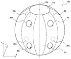
- FIG. 1B is an explanatory diagram for explaining another example of the schematic configuration of the all-sky camera.
- the all-sky camera 10b shown in FIG. 1B has a housing 11b formed in a substantially spherical shape that is cut at the top and bottom surfaces orthogonal to the axis 13b.
- Four pairs of camera modules having fields of view adjacent to each other in the elevation angle direction are arranged on the outer peripheral surface of the housing 11b. More specifically, a pair of camera modules 20i and 20j, a pair of camera modules 20k and 20m, a pair of camera modules 20n and 20p, and a pair of camera modules 20q and 20r are 90 in the azimuth direction between adjacent pairs. They are arranged at intervals of °.
- each camera module 20 captures a field of view of the camera module and generates a captured image.
- the camera module 20i generates a first image signal by imaging the first visual field.
- the camera module 20j generates a second image signal by capturing an image of the second visual field adjacent to the first visual field in the elevation angle direction.
- the optical axes of the two camera modules 20 of each pair extend radially in the vertical plane.
- an image covering the entire 360 ° field of view in the azimuth direction can be obtained.
- FIGS. 1A and 1B the configuration of the all-sky camera shown in FIGS. 1A and 1B is only an example.
- the technology according to the present disclosure may be applied to a camera of any shape including any number of camera modules of two or more.
- Reading pixel values from the image sensor is usually performed by a rolling shutter system or a global shutter system.
- a CCD Charge Coupled Device
- CMOS Complementary Metal Oxide Semiconductor
- Reading pixel values by the rolling shutter method is also called a sequential reading method.
- the charge accumulated in each pixel is normally changed from the upper line to the lower line in the two-dimensional focal plane and from the left pixel to the right pixel in each line. It is read sequentially as a value.
- the pixel readout direction of the sequential readout method there can be two typical patterns in the arrangement of the camera module, that is, landscape and portrait.
- FIG. 2A is an explanatory diagram for describing a first example of the arrangement of a plurality of camera modules adjacent in the azimuth angle direction.
- the fields of view of a plurality of camera modules are two-dimensionally represented using a horizontal axis representing the azimuth angle ⁇ and a vertical axis representing the elevation angle ⁇ .
- the field of view Fv1a is the field of view of the camera module 20a.
- the field of view Fv1b is the field of view of the camera module 20b.
- the field of view Fv1c is the field of view of the camera module 20c.
- the visual fields Fv1a and Fv1b are adjacent to each other in the azimuth direction and include both overlapping portions Fo1a.
- the visual fields Fv1b and Fv1c are adjacent to each other in the azimuth direction and include both overlapping portions Fo1b.
- the camera module 20 determines the pixel value of each pixel in its field of view from the left in each horizontal line and in each line, as indicated by an arrow in the figure. Read right.
- the field of view Fv1a of the camera module 20a precedes the field of view Fv1b of the camera module 20b in the pixel readout direction.
- the field of view Fv1b of the camera module 20b precedes the field of view Fv1c of the camera module 20c in the pixel readout direction.
- the time until the reading timing reaches the overlapping portion Fo1a is smaller than the time required for reading one line by the ratio of the overlapping portion.
- FIG. 2B is an explanatory diagram for describing a second example of the arrangement of a plurality of camera modules adjacent in the azimuth direction.
- the field of view Fv2a is the field of view of the camera module 20a.
- the field of view Fv2b is the field of view of the camera module 20b.
- the field of view Fv2c is the field of view of the camera module 20c.
- the visual fields Fv2a and Fv2b are adjacent to each other in the azimuth direction and include both overlapping portions Fo2a.
- the visual fields Fv2b and Fv2c are adjacent to each other in the azimuth direction and include both overlapping portions Fo2b.
- the camera module 20 When the camera module 20 is arranged vertically, the camera module 20 sets the pixel value of each pixel in its field of view from the bottom in each vertical line and in each line, as indicated by an arrow in the figure. Read up. Therefore, for example, the field of view Fv2a of the camera module 20a precedes the field of view Fv2b of the camera module 20b in the pixel readout direction. The field of view Fv2b of the camera module 20b precedes the field of view Fv2c of the camera module 20c in the pixel readout direction. For example, after the pixel value reading of the camera module 20a is started, the time until the reading timing reaches the overlapping portion Fo2a is smaller than the time required for reading all lines in the focal plane by the ratio of the overlapping portion.
- FIG. 3A is an explanatory diagram for describing a first example of the arrangement of a plurality of camera modules that are also adjacent in the elevation angle direction.
- the fields of view of the plurality of camera modules are two-dimensionally represented using a horizontal axis representing the azimuth angle ⁇ and a vertical axis representing the elevation angle ⁇ .
- the field of view Fv3i is the field of view of the camera module 20i.
- the field of view Fv3j is the field of view of the camera module 20j.
- the field of view Fv3k is the field of view of the camera module 20k.
- the visual fields Fv3i and Fv3j are adjacent to each other in the elevation angle direction and include both overlapping portions Fo3ij.
- the visual fields Fv3i and Fv3k are adjacent to each other in the azimuth direction and include both overlapping portions Fo3ik.
- the camera module 20 sets the pixel value of each pixel in its field of view from the bottom in each vertical line and in each line, as indicated by an arrow in the figure. Read up. Therefore, for example, the visual field Fv3i of the camera module 20i precedes the visual field Fv3j of the camera module 20j and precedes the visual field Fv3k of the camera module 20k in the pixel readout direction.
- the time until the reading timing reaches the overlapping portion Fo3ij is smaller than the time required for reading one line by the ratio of the overlapping portion.
- FIG. 3B is an explanatory diagram for describing a second example of the arrangement of a plurality of camera modules adjacent also in the elevation angle direction.
- the field of view Fv4j is the field of view of the camera module 20j.
- the field of view Fv4m is the field of view of the camera module 20m.
- the field of view Fv4i is the field of view of the camera module 20i.
- the visual fields Fv4j and Fv4m are adjacent to each other in the azimuth direction and include both overlapping portions Fo4jm.
- the visual fields Fv4j and Fv4i are adjacent to each other in the elevation angle direction and include both overlapping portions Fo4ji.
- the camera module 20 determines the pixel value of each pixel in its field of view from the left in each horizontal line and in each line, as indicated by an arrow in the figure. Read right. Therefore, for example, the visual field Fv4j of the camera module 20j precedes the visual field Fv4m of the camera module 20m and precedes the visual field Fv4i of the camera module 20i in the pixel readout direction. For example, after the pixel value reading of the camera module 20j is started, the time until the reading timing reaches the overlapping portion Fo4ji is smaller than the time required for reading all lines in the focal plane by the ratio of the overlapping portion.
- phase shift between camera modules As described above, in the sequential readout method, for example, when the first field of view captured by the first imaging unit and the second field of view captured by the second imaging unit partially overlap, The phase of the corresponding image signal is different between the first image signal generated by the first imaging unit and the second image signal generated by the second imaging unit.
- the phase here may be understood to mean a timing at which a pixel value at a certain pixel position is read out within one frame time.
- FIG. 4A is an explanatory diagram for explaining a phase shift between two camera modules arranged horizontally and adjacent in the azimuth direction.
- the field of view Fv1a is the field of view of the camera module 20a.
- the field of view Fv1b is the field of view of the camera module 20b.
- the pixel P11a and the pixel P12a are pixels in the field of view Fv1a.
- the pixel P11b and the pixel P12b are pixels in the visual field Fv1b.
- the pixel value of the pixel P11b is also read by the camera module 20b, but the pixel value of the pixel P12a at substantially the same position is not read by the camera module 20a at this time. Thereafter, when a certain time elapses, the camera module 20a reads the pixel value of the pixel P12a.
- the camera module 20b reads the pixel value of the pixel P12b.
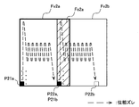
- FIG. 4B is an explanatory diagram for explaining a phase shift between two camera modules arranged vertically and adjacent in the azimuth direction.
- the field of view Fv2a is the field of view of the camera module 20a.
- the field of view Fv2b is the field of view of the camera module 20b.
- the pixel P21a and the pixel P22a are pixels in the field of view Fv2a.
- the pixel P21b and the pixel P22b are pixels in the visual field Fv2b.
- the pixel value of the pixel P21b is read by the camera module 20b, but the pixel value of the pixel P22a at substantially the same position is not read by the camera module 20a at this time.
- the camera module 20a reads the pixel value of the pixel P22a.
- the camera module 20b reads the pixel value of the pixel P22b.
- FIG. 5A is an explanatory diagram for explaining a phase shift between two camera modules arranged vertically and adjacent to each other in the elevation angle direction.
- the field of view Fv3i is the field of view of the camera module 20i.
- the field of view Fv3j is the field of view of the camera module 20j.
- the pixel P31i and the pixel P32i are pixels in the visual field Fv3i.
- the pixel P31j and the pixel P32j are pixels in the field of view Fv3j.
- the pixel value of the pixel P31j is read by the camera module 20j, but the pixel value of the pixel P32i at substantially the same position is not read by the camera module 20i at this time.
- the camera module 20i reads the pixel value of the pixel P32i.
- the camera module 20j reads the pixel value of the pixel P32j.
- FIG. 5B is an explanatory diagram for explaining a phase shift between two camera modules arranged horizontally and adjacent in the elevation angle direction.
- the field of view Fv4j is the field of view of the camera module 20j.
- the field of view Fv4i is the field of view of the camera module 20i.
- the pixel P41j and the pixel P42j are pixels in the visual field Fv4j.
- the pixel P41i and the pixel P42i are pixels in the field of view Fv4i.
- the pixel value of the pixel P41i is read by the camera module 20i.
- the pixel value of the pixel P42j at substantially the same position is not read by the camera module 20j at this time.
- the camera module 20j reads the pixel value of the pixel P42j.
- the camera module 20i reads the pixel value of the pixel P42i.
- the phase shift described with reference to FIGS. 4A to 5B is a captured image showing adjacent fields of view when a fast-moving subject is imaged by the omnidirectional camera or when imaging is performed while moving the camera quickly. Inconsistent in the appearance of the subject or background between the two, reducing the accuracy of the integrated processing such as stitching or stereo matching. Therefore, in the camera system described in detail in the next section, control of imaging timing for eliminating such phase shift is introduced.
- FIG. 6 is a schematic diagram illustrating an example of a configuration of a camera system according to an embodiment.
- the camera system 1 may include an imaging device 100, a server 160, and display terminals 170a and 170b.
- the imaging apparatus 100 includes, for example, a plurality of imaging units (camera modules) each having a plurality of fields of view so as to integrally cover the entire 360 ° field of view around a certain reference axis.
- the imaging apparatus 100 may include any number of imaging units, and the imaging units may have any arrangement.
- the imaging device 100 is an all-sky camera placed in the imaging environment 102.
- the imaging device 100 may be, for example, a stand-alone device that records a captured image in a local memory. Further, the imaging device 100 may be connected to the server 160 or the display terminal 170a or 170b via the network 165.
- the server 160 is an information processing apparatus that accumulates captured images generated by the imaging apparatus 100 (or reproduction images generated from the captured images through integrated processing).
- the server 160 receives an image from the imaging apparatus 100 via the network 165 or via a direct connection line (not shown), and stores the received image in a storage medium.
- the server 160 distributes the image received from the imaging device 100 to the display terminal 170 in response to a request received from the display terminal 170 (170a or 170b). Note that when the imaging device 100 and the display terminal 170 are directly connected, the camera system 1 may not include the server 160.
- the network 165 may be a public network such as the Internet, or may be a private network such as a home network or a corporate network.
- Network 165 may include any combination of wireless and wired links.
- the display terminal 170a is a terminal device having a function of displaying an image captured by the imaging device 100.
- the display terminal 170a is a wearable terminal worn on the user's head.
- the user can reproduce an image captured by the imaging apparatus 100 on the screen of the display terminal 170a.
- the image imaged by the imaging device 100 is, for example, an all-sky image (each frame constituting a still image or a moving image) that integrally covers the entire 360 ° field of view.
- the display image of the reproduction visual field corresponding to that direction among the all-sky images can be reproduced.
- the reproduction visual field changes, and the display image of the reproduction visual field after the change can be reproduced. .
- the display terminal 170b is also a terminal device having a function of displaying an image captured by the imaging device 100.
- the display terminal 170b is a mobile terminal held by the user.
- the user can reproduce the all-sky image captured by the imaging device 100 on the screen of the display terminal 170b.
- the display terminal 170b faces a certain direction, a display image of a reproduction visual field corresponding to that direction among all the sky images can be reproduced.
- the reproduction visual field is changed, and the display image of the reproduction visual field after the change is reproduced. obtain.
- the display terminal 170 may acquire the whole sky image directly from the imaging device 100 or may obtain the whole sky image from the server 160.
- the process of constructing the whole sky image or individual display image from the captured images generated by the plurality of imaging units of the imaging device 100 may be performed by any of the imaging device 100, the server 160, and the display terminal 170.
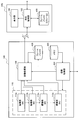
- FIG. 7 shows an example of the configuration of the imaging apparatus 100 according to an embodiment.
- the imaging apparatus 100 includes a multi-camera unit 110, an imaging control unit 120, a memory 125, an image processing unit 130, and a frame buffer 135.
- the multi-camera unit 110 includes a plurality of imaging units 112a, 112b, 112c,.
- the first imaging unit 112 a generates a first image signal by imaging the first visual field, and outputs the generated first image signal to the image processing unit 130.
- the second imaging unit 112b generates a second image signal by imaging the second visual field, and outputs the generated second image signal to the image processing unit 130.
- the second field of view partially overlaps the first field of view.
- the third imaging unit 112c generates a third image signal by imaging the third field of view, and outputs the generated third image signal to the image processing unit 130.
- the third field of view partially overlaps at least one of the first field of view and the second field of view.
- the nth imaging unit 112n generates an nth image signal by imaging the nth field of view, and outputs the generated nth image signal to the image processing unit 130.
- All or a subset of the fields of view of the plurality of imaging units 112a, 112b, 112c,..., 112n can integrally cover the entire 360 ° field around a certain reference axis.
- the reference axis is the vertical axis, and the entire 360 ° field of view in the azimuth direction is covered by a plurality of fields of view.
- the technology according to the present disclosure can be applied to any inclination of the reference axis.
- the first imaging unit 112a includes a CMOS image sensor (not shown) that photoelectrically converts an image of light incident from the first field of view through a lens into an electrical signal, and sequentially reads from the image sensor.
- the first image signal is generated by reading out the pixel value at.
- the second imaging unit 112b includes a CMOS image sensor (not shown) that photoelectrically converts an image of light incident through the lens from the second field of view into an electrical signal, and sequentially reads from the image sensor.
- the second image signal is generated by reading out the pixel value.
- Other imaging units 112 can also generate respective image signals in the same manner as the first imaging unit 112a and the second imaging unit 112b, except that each imaging unit 112 has its own field of view.
- the first field of view of the first imaging unit 112a and the second field of view of the second imaging unit 112b are adjacent to each other in the azimuth direction.
- the first imaging unit 112a and the second imaging unit 112b are both arranged vertically, and read out pixel values for each vertical line.
- the relationship between the first and second visual fields corresponds to the relationship between the visual field Fv2a and the visual field Fv2b illustrated in FIG. 2B.
- first field of view of the first imaging unit 112a and the second field of view of the second imaging unit 112b are adjacent in the azimuth direction.
- first imaging unit 112a and the second imaging unit 112b are both arranged horizontally and read pixel values for each horizontal line.
- the relationship between the first and second visual fields corresponds to the relationship between the visual field Fv1a and the visual field Fv1b illustrated in FIG. 2A.
- first field of view of the first imaging unit 112a and the second field of view of the second imaging unit 112b are adjacent in the elevation angle direction.
- the first imaging unit 112a and the second imaging unit 112b are both arranged vertically, and read out pixel values for each vertical line.
- the relationship between the first and second visual fields in this case corresponds to the relationship between the visual field Fv3i and the visual field Fv3j illustrated in FIG. 3A.
- first field of view of the first imaging unit 112a and the second field of view of the second imaging unit 112b are adjacent in the elevation angle direction.
- first imaging unit 112a and the second imaging unit 112b are both arranged horizontally and read pixel values for each horizontal line.
- the relationship between the first and second visual fields in this case corresponds to the relationship between the visual field Fv4j and the visual field Fv4i illustrated in FIG. 3B.
- the imaging control unit 120 is a controller module that controls the imaging operation in the multi-camera unit 110.
- the imaging control unit 120 starts imaging of all-round images in the multi-camera unit 110 in response to an imaging start trigger detected via, for example, some user interface (not shown) or a communication interface (not shown).
- an imaging start trigger detected via, for example, some user interface (not shown) or a communication interface (not shown).
- the imaging control unit 120 controls the imaging timing of each imaging unit 112 of the multi-camera unit 110 for the imaging operation of each frame. For example, the imaging control unit 120 sets the imaging timing of at least one of the first image signal generated in the first imaging unit 112a and the second image signal generated in the second imaging unit 112b to the first Control is performed so that the phase of the first image signal and the phase of the second image signal corresponding to the overlapping portion of the visual field and the second visual field coincide. In addition, the imaging control unit 120 similarly controls the imaging timings of the pairs of other imaging units having fields that partially overlap each other so that the phases of the image signals corresponding to the overlapping parts are matched between the pairs. To do.
- the imaging control unit 120 determines that the read pixel position in the first imaging unit 112a is the first pixel in the second imaging unit 112b only for the time from when the first pixel reaches the overlapping portion of the first visual field and the second visual field.
- the reading of the pixel value of each pixel can be delayed.
- FIG. 8 to 11 show the imaging control unit 120 for each of combinations of two arrangement patterns (horizontal / vertical placement) of the imaging unit and two adjacent directions (azimuth angle direction / elevation angle direction) of the imaging unit.
- 2 shows an example of control of imaging timing by.
- a timing chart for reading pixel values when imaging timing control is not performed is shown on the left side, and pixels when imaging timing control is performed by the imaging control unit 120 are shown on the right side.
- a timing chart for reading values is shown.
- the horizontal axis of each timing chart represents the phase of the image signal, and the vertical axis represents the pixel position that is one-dimensionalized according to the reading order of the sequential reading method.
- FIG. 8 corresponds to a case where the first imaging unit 112a and the second imaging unit 112b are arranged horizontally, and the fields of view of these imaging units are adjacent in the azimuth direction.
- the solid line represents the imaging timing (pixel value reading timing) for each pixel position of the first image signal Im1a generated by the first imaging unit 112a, and the broken line is generated by the second imaging unit 112b.
- the imaging timing for each pixel position of the second image signal Im1b is represented.
- the imaging of the first image signal Im1a is started at the pixel P11a, and at the same time, the imaging of the second image signal Im1b is performed at the pixel. It starts at P11b.
- the pixel P11b of the second image signal Im1b occupies substantially the same position as the pixel P12a of the first image signal Im1a in the integrated field of view, but at this time, the pixel value of the pixel P12a of the first image signal Im1a Is not read. Thereafter, when the time ⁇ 1 has elapsed, the pixel value of the pixel P12a is read out by the first imaging unit 112a.
- the imaging control unit 120 changes the read pixel position in the first imaging unit 112a from the first pixel P11a to the first pixel P12a of the overlapping portion.
- the readout of the pixel value of the first pixel P11b in the second imaging unit 112b is delayed by the time ⁇ 1 until the time is reached.
- the phase of the first image signal Im1a matches the phase of the second image signal Im1b for the pixels belonging to the overlapping field of view.
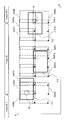
- FIG. 9 corresponds to a case where the first imaging unit 112a and the second imaging unit 112b are arranged vertically and the fields of view of these imaging units are adjacent in the azimuth direction.
- the solid line represents the imaging timing (pixel value reading timing) for each pixel position of the first image signal Im2a generated by the first imaging unit 112a, and the broken line is generated by the second imaging unit 112b.
- the imaging timing for each pixel position of the second image signal Im2b is shown.
- the imaging of the first image signal Im2a is started at the pixel P21a, and at the same time, the imaging of the second image signal Im2b is performed at the pixel. It starts at P21b.
- the pixel P21b of the second image signal Im2b occupies substantially the same position as the pixel P22a of the first image signal Im2a in the integrated visual field, but at this time, the pixel value of the pixel P22a of the first image signal Im2a Is not read. Thereafter, when the time ⁇ 2 has elapsed, the pixel value of the pixel P22a is read out by the first imaging unit 112a.
- the imaging control unit 120 changes the read pixel position in the first imaging unit 112a from the first pixel P21a to the first pixel P22a of the overlapping portion.
- the readout of the pixel value of the first pixel P21b in the second imaging unit 112b is delayed by the time ⁇ 2 until the time is reached.
- the phase of the first image signal Im2a matches the phase of the second image signal Im2b for the pixels belonging to the overlapping portion of the visual field.
- FIG. 10 corresponds to a case where the first imaging unit 112a and the second imaging unit 112b are arranged vertically and the fields of view of these imaging units are adjacent in the elevation angle direction.
- a solid line represents imaging timing (pixel value reading timing) for each pixel position of the first image signal Im3a generated by the first imaging unit 112a, and a broken line is generated by the second imaging unit 112b.
- the imaging timing for each pixel position of the second image signal Im3b is shown.
- the imaging of the first image signal Im3a is started at the pixel P31i, and at the same time, the imaging of the second image signal Im3b is performed at the pixel. It starts at P31j.
- the pixel P31j of the second image signal Im3b occupies substantially the same position as the pixel P32i of the first image signal Im3a in the integrated visual field, but at this time, the pixel value of the pixel P32i of the first image signal Im3a Is not read. Thereafter, when the time ⁇ 3 has elapsed, the pixel value of the pixel P32i is read out by the first imaging unit 112a.
- the imaging control unit 120 changes the read pixel position in the first imaging unit 112a from the first pixel P31i to the first pixel P32i of the overlapping portion.
- the readout of the pixel value of the leading pixel P31j in the second imaging unit 112b is delayed by the time ⁇ 3 until the time is reached.
- the phase of the first image signal Im3a matches the phase of the second image signal Im3b for the pixels belonging to the overlapping portion of the visual field.
- FIG. 11 corresponds to a case where the first imaging unit 112a and the second imaging unit 112b are arranged horizontally and the fields of view of these imaging units are adjacent to each other in the elevation angle direction.
- a solid line represents the imaging timing (pixel value reading timing) for each pixel position of the first image signal Im4a generated by the first imaging unit 112a, and a broken line is generated by the second imaging unit 112b.
- the imaging timing for each pixel position of the second image signal Im4b is represented.
- imaging of the first image signal Im4a is started at the pixel P41j, and at the same time, imaging of the second image signal Im4b is performed on the pixel. It starts at P41i.
- the pixel P41i of the second image signal Im4b occupies substantially the same position as the pixel P42j of the first image signal Im4a in the integrated field of view, but at this time, the pixel value of the pixel P42j of the first image signal Im4a Is not read. Thereafter, when the time ⁇ 4 has elapsed, the pixel value of the pixel P42j is read out by the first imaging unit 112a.
- the imaging control unit 120 changes the read pixel position in the first imaging unit 112a from the first pixel P41j to the first pixel P42j of the overlapping portion.
- the reading of the pixel value of the first pixel P41i in the second imaging unit 112b is delayed by the time ⁇ 4 until reaching.
- the phase of the first image signal Im4a matches the phase of the second image signal Im4b for the pixels belonging to the overlapping portion of the visual field.
- the delay times ⁇ 1 and ⁇ 3 of the case illustrated in FIG. 8 (horizontal placement, adjacent in the azimuth direction) and the case illustrated in FIG. 10 (vertical placement, adjacent in the elevation angle direction) are the time required to read one line. Shorter than. Therefore, the imaging control unit 120 does not need to relatively delay the imaging timing for the pair of imaging units 112 corresponding to these cases by ignoring the phase shift that has a small influence on the integrated processing.
- the memory 125 may store timing control information that predefines the delay time ⁇ 1, ⁇ 2, ⁇ 3, or ⁇ 4 as described with reference to FIGS.
- the timing control information is, for example, a delay time of the imaging timing of the second imaging unit 112b based on the imaging timing of the first imaging unit 112a (that is, a delay time of the imaging timing of the second image signal with respect to the first image signal). ) As well as the delay time of the imaging timing of each of the other imaging units 112c to 112n.
- the imaging control unit 120 acquires timing control information that predefines such a delay time in association with each imaging unit 112 from the memory 125, and sends an imaging start instruction signal to each imaging unit 112 according to the acquired timing control information. Also good.
- the timing control information from the imaging control unit 120 to the first imaging unit 112a, from the first imaging unit 112a to the second imaging unit 112b, from the second imaging unit 112b to the third imaging unit 112c (hereinafter the same)
- the imaging start instruction signal is sequentially transferred between the imaging units 112 having adjacent fields of view, using the imaging start instruction signal sent from the imaging control unit 120 to the first imaging unit 112a as a trigger. Good.
- the imaging control unit 120 dynamically determines the delay time of the imaging timing of the other imaging units 112b to 112n with reference to the imaging timing of the first imaging unit 112a, and according to the determined delay time An imaging start instruction signal may be sent to each imaging unit 112.
- the delay time of the imaging timing between the two imaging units 112 having adjacent fields of view can depend on the frame time as described later. Therefore, for example, the imaging control unit 120 can dynamically determine a delay time to be applied to each imaging unit depending on a required frame time (or a required frame rate) that can be variably set.
- the imaging control unit 120 sets the pixel readout speed in the first imaging unit 112a to the top pixel (for example, the pixel P11a in FIG. 8, the pixel P21a in FIG. 9, the pixel P31i in FIG. Pixel value within the range from the pixel P41j) to the overlapping portion (for example, the pixel P12a in FIG. 8, the pixel P22a in FIG. 9, the pixel P32i in FIG. 10, or the pixel P42j in FIG. 11) in the second imaging unit 112b. It is desirable to control the pixel reading speed in the first imaging unit 112a so that the pixel value is read within a delay time (for example, ⁇ 1, ⁇ 2, ⁇ 3, or ⁇ 4).
- a delay time for example, ⁇ 1, ⁇ 2, ⁇ 3, or ⁇ 4
- the N CAM imaging units 112 may be all of the imaging units included in the multi-camera unit 110, or a subset of the imaging units (for example, the four camera modules on the upper surface side in the example of FIG. 1B, or the bottom surface). 4 camera modules on the side).
- the imaging timing of the first imaging unit 112a is the earliest among the N CAM-number of the imaging unit 112, the imaging timing of the n image pickup unit 112n is assumed slowest.
- the field of view of the n-th imaging unit 112n is adjacent to the field of view of the first imaging unit 112a (in the direction opposite to the pixel readout direction). From the viewpoint of the imaging timing, the imaging of the first imaging unit 112a of the i-th frame is performed after the imaging of the n-th imaging unit 112n of the i-1th frame.
- the captured image of the n ⁇ 1 imaging unit 112n of the i ⁇ 1th frame and the i th frame are controlled.
- the phase shift in the overlapping portion with the captured image of the first imaging unit 112a can be eliminated for an arbitrary integer i, and the integrated processing of the captured images can be facilitated.
- the frame time T FRAME that is the reciprocal of the required frame rate of the all-sky image and the reference axis that can be the vertical axis
- r OL in the formula (1) represents in the captured image of one imaging unit 112, the ratio of the overlapped portion of the captured image of the other one of the imaging section 112.
- TFP is the time required for one imaging unit 112 to read a captured image of one focal plane.
- the delay time ⁇ of the imaging timing between the two imaging units 112 having adjacent fields of view can be determined as follows based on Expression (1).
- N is CAM pieces of read delay time of the pixel value ⁇ in the first imaging unit second imaging unit 112b for 112a in the imaging section 112, dividing the required frame time T FRAME by the number N CAM imaging unit 112 Is equal to the quotient
- the delay time between any two adjacent image capturing units 112 may be the same value.
- the pixel readout speed S FP in each imaging unit 112 may be, for example, a quotient obtained by dividing the total number of pixels in one focal plane by the focal plane time T FP .
- the calculation of the delay time ⁇ and the pixel readout speed S FP may be performed in advance (for example, when the camera is manufactured or after calibration is performed). In that case, timing control information that defines the delay time of the imaging timing of each imaging unit 112 and readout control information that defines the pixel readout speed S FP can be generated and stored in the memory 125.
- the imaging control unit 120 may dynamically calculate one or both of the delay time of the imaging timing and the pixel readout speed of each imaging unit 112 using the parameters described above.
- FIG. 12 is an explanatory diagram for describing an example of an all-sky image captured with no phase shift over a plurality of frames.
- the i-th frame of the whole sky image includes eight captured images Im51a, Im51b, Im51c, Im51d, Im51e, Im51f, Im51g, and Im51h.
- the imaging timing of these captured images is delayed by a delay time ⁇ sequentially from the preceding captured image in the pixel readout direction, and 8 times ⁇ is equal to the frame time T FRAME . That is, the product of the delay time ⁇ and the number N CAM of the imaging units 112 is equal to the frame time T FRAME of the whole sky image, and the total of the phase delays corresponds to 360 °.
- the phase of the overlapping portion also matches between the imaged image Im50h captured latest in the (i-1) th frame and the imaged image Im51a captured earliest in the i-th frame, and the i-th frame
- the phase of the overlapping portion also coincides between the latest captured image Im51h that is captured and the captured image Im52a that is captured earliest in the (i + 1) th frame.
- the image processing unit 130 or the display terminal 170 described later has a case where the visual field to be processed (or the reproduction target) straddles the phase origin (the point where the phase is zero or 360 ° in FIG. 12).
- the captured image of the earliest field of view of the i (or i + 1) th frame and the captured image of the slowest field of view of the i-1 (or i) frame are integrated without being affected by the phase shift. Can be processed.
- the all-sky image generally represents the image of the field of view around the camera two-dimensionally according to a cylindrical projection (for example, an equirectangular projection or an epicylinder projection).
- the field of view circulates in one dimension of the image and the field of view does not circulate in the other dimension.
- a circular visual field is applied in the azimuth direction and a non-circular visual field is applied in the elevation angle direction in accordance with the characteristics of the human visual system.
- the delay time of the imaging timing between the imaging units 112 having the visual fields adjacent to each other in the non-circulating direction may be determined by any method as long as the phases of the image signals of the overlapping portions of the visual field match. Further, when the phase shift is small and the influence on the image quality can be ignored, the delay time may not be set.
- the image processing unit 130 integrally processes images represented by image signals input from the plurality of imaging units 112 of the multi-camera unit 110 to generate an output image.
- the image signals input from the plurality of imaging units 112 represent captured images that show different visual fields.
- the image processing unit 130 may generate a composite image by stitching the captured images using partial images in an overlapping portion of two captured images showing adjacent fields of view.
- the image processing unit 130 may determine the parallax of the subject by performing stereo matching using two captured images that overlap each other.
- the image processing unit 130 may generate a depth map representing the result of the parallax determination, or may generate a stereoscopic image of the whole sky.
- the image processing unit 130 displays the images on another device (for example, the server 160 described with reference to FIG. 6 or the display for storing or reproducing the whole sky image including a plurality of captured images. It may simply be transferred to the terminal 170).
- the image processing unit 130 may compress and encode the image using an arbitrary image compression method before transferring the image.
- the image processing unit 130 when the visual field to be processed crosses the phase origin, the captured image of the i (or i + 1) th frame and the i-1 (or i) th frame.
- the influence of the phase shift may be avoided by integrally processing the captured image of the frame.
- the frame buffer 135 can buffer not only the latest captured image captured by the imaging unit 112 but also the captured image of the immediately preceding frame.
- FIG. 7 also shows an example of the configuration of the display terminal 170 according to an embodiment.
- the display terminal 170 includes a playback control unit 180, a frame buffer 185, and a display unit 190.
- the reproduction control unit 180 acquires an all-sky image output from the imaging device 100 in response to a reproduction start trigger detected via some user interface (not shown), for example.
- the whole sky image is reproduced on the screen of the display unit 190.
- the reproduction control unit 180 may receive an image directly from the imaging device 100 or may receive an image via an intermediate device such as the server 160.
- the all-sky image acquired by the reproduction control unit 180 is typically composed of a plurality of images showing different visual fields for each frame.
- Each image may be a captured image itself generated by the imaging unit 112 of the imaging device 100, or an image generated by processing the captured image (for example, a stereoscopic view including a right eye image and a left eye image). Image).
- the reproduction control unit 180 trims or connects one or more images corresponding to the reproduction visual field instructed by the user (or autonomously determined according to the attitude of the terminal, for example), and Build a display image. Then, the reproduction control unit 180 outputs the constructed display image to the display unit 190.
- FIG. 13 is an explanatory diagram for explaining some examples of display images that can be constructed according to various reproduction fields of view.
- the field of view of eight imaging units 112 covers a 360 ° field of view in the azimuth direction, and two image capturing units 112 cover an integrated field of view in the elevation angle direction.
- the total sky image of one frame is composed of a total of 16 images.
- the reproduction visual field is smaller than the entire visual field of the whole sky image.
- FIG. 13 shows three exemplary reproduction fields of view Fr1, Fr2, and Fr3 in a thick rectangle.
- the playback control unit 180 acquires, for example, the image Im60p of the (i-1) th frame and the images Im61b and Im61d of the i-th frame, and trims and connects necessary portions from these images Im60p, Im61b, and Im61d.
- a display image of the reproduction visual field Fr1 can be constructed.
- the reproduction control unit 180 can acquire the images Im61e, Im61g, and Im61i of the i-th frame, trim the necessary portions from them, and connect them to construct a display image of the reproduction visual field Fr2.
- the playback control unit 180 obtains the images Im61m, Im61n, Im61o and Im61p of the i-th frame, and the images Im62a and Im62b of the i + 1-th frame, and trims and connects the necessary parts therefrom.
- a display image of the reproduction visual field Fr3 can be constructed.
- the subject J1 is shown in the reproduction visual field Fr1, but there is no phase shift between the partial images constituting the display image of the reproduction visual field Fr1 even though the partial images are captured by different camera modules.
- the image of the subject J1 can be reproduced without distortion or failure.
- the subject J1 is also shown in the reproduction visual field Fr3, since there is no phase shift between the partial images constituting the display image of the reproduction visual field Fr3, the image of the subject J1 can be reproduced without distortion or failure.
- the display image of the playback field of view Fr3 is constructed from the images Im61a, Im61b, Im61m, Im61n, Im61o and Im61p of the i-th frame, the phase between the images Im61a and Im61b and the remaining images
- the image of the subject J1 should have collapsed due to the deviation. However, such a failure can be prevented by the method described in the above embodiment.
- the frame buffer 185 buffers individual images constituting the entire sky image (still image or moving image) acquired by the reproduction control unit 180 over the past two frames. As a result, regardless of the direction of the entire 360 ° field of view, the playback control unit 180 has access to all the partial images required to properly construct the display image of the playback field of view. Can do.
- the display unit 190 is typically a display device that can include a screen and a display driver.
- the display unit 190 reproduces the display image of the reproduction visual field input from the reproduction control unit 180 on the screen.
- the screen may correspond to, for example, a micro display in the glasses-type wearable terminal 170a shown in FIG. 6 and a touch panel in the mobile terminal 170b.
- the present invention is not limited to these examples, and the whole sky image may be displayed on a monitor of a fixed terminal such as a PC (Personal Computer) or a television device. Further, the whole sky image may be projected on a screen by a projector.
- FIG. 14 is a flowchart illustrating an example of the flow of an imaging control process that can be executed by the imaging control unit 120 according to an embodiment.
- the imaging control unit 120 acquires control information for controlling the imaging operation in the multi-camera unit 110 (step S110).
- the control information acquired here may include timing control information that defines a delay time of the imaging timing of each of the plurality of imaging units 112 and readout control information that defines a pixel readout speed.
- the imaging control unit 120 waits for an imaging start trigger (step S115). For example, when a user input that instructs to start imaging is detected via the user interface or a control command that instructs to start imaging is detected via the communication interface, the imaging control process proceeds to step S120.
- the imaging control unit 120 supplies an imaging start instruction signal to the first imaging unit 112a that should operate at the earliest timing among the plurality of imaging units 112 (step S120).
- the first imaging unit 112a is triggered by the supplied imaging start instruction signal, and starts reading pixel values sequentially from the top pixel of the focal plane using a readout method.
- the pixel readout speed in each imaging unit 112 may be specified by an imaging start instruction signal, or may be set via a separate control signal.
- Step S125 when the delay time defined by the timing control information elapses and the imaging timing of the second imaging unit 112b to operate next arrives (step S125), an imaging start instruction signal is supplied to the second imaging unit 112b. (Step S130). The waiting of the delay time and the supply of the imaging start signal are repeated until imaging of all the fields of view is started (step S135).
- the image processing unit 130 integrally processes captured images that are captured at different timings by the plurality of imaging units 112 and reflect different fields of view (step S140).
- the imaging control unit 120 supplies an imaging start instruction signal to the first imaging unit 112a again (step S120). Such imaging of the whole sky image can be repeated until the end of imaging is instructed.
- FIG. 15A is a flowchart illustrating an example of a detailed flow of a control information acquisition process that can be executed in step S110 of FIG.
- the imaging control unit 120 sets timing control information that defines imaging timing for each module determined in advance in consideration of the frame time T FRAME of the all-sky image and the camera module number N CAM . Obtained from the memory 125 (step S111).
- the imaging control unit 120 acquires read control information that defines a predetermined pixel read speed from the memory 125 (step S112).
- FIG. 15B is a flowchart showing another example of the detailed flow of the control information acquisition process that can be executed in step S110 of FIG.
- the imaging control unit 120 determines the imaging timing for each module (for example, the imaging timing of one imaging unit 112 based on the frame time T FRAME of the all-sky image and the number N CAM of camera modules. A reference delay time of imaging timing of the other imaging unit 112 is determined, and timing control information indicating the determined imaging timing is generated (step S113).
- the imaging control unit 120 determines the pixel readout speed based on parameters such as the total number of pixels in one focal plane and the focal plane time, for example, and generates readout control information indicating the determined pixel readout speed ( Step S114).
- FIG. 16 is a flowchart illustrating an example of a flow of a reproduction control process that can be executed by the display terminal 170 according to an embodiment.
- the playback control unit 180 of the display terminal 170 determines the playback field of view based on an instruction from the user or a measurement result of the attitude of the terminal, for example, when playback of the whole sky image is started (step S181). Subsequent processing branches depending on whether the determined reproduction field of view crosses the phase origin (step S183).
- the reproduction control unit 180 acquires one or more images corresponding to the reproduction visual field from the image set constituting the single frame all-sky image (step S185). On the other hand, when the reproduction visual field crosses the phase origin, the reproduction control unit 180 acquires a plurality of images corresponding to the reproduction visual field from the image set constituting the whole sky image over a plurality of frames (step S187).
- the playback control unit 180 trims or connects one or more images acquired in step S185 or S187 according to the playback field of view, and constructs a display image of the playback field of view (step S189).
- the display unit 190 reproduces the display image of the reproduction visual field constructed by the reproduction control unit 180 on the screen (step S191). Such reproduction of the whole sky image may be repeated until the end of reproduction is instructed (step S193).
- the imaging timing of at least one of the two imaging units that respectively capture the fields of view that partially overlap each other and generate the image signal is the image signal corresponding to the overlapping portion of the fields of view. Control is made so that the phases match. That is, since the phase shift between the two imaging units is suppressed, it is possible to prevent the integrated processing of the captured images from the two imaging units from becoming difficult due to the phase shift. For example, even if a fast-moving subject or background appears in the captured image, the accuracy of the integrated processing does not decrease. Even if two captured images are combined, the subject or background image present in the overlapping field of view does not fail.
- CMOS complementary metal-oxide-semiconductor
- the technology according to the present disclosure enables low-cost manufacturing or downsizing of an omnidirectional camera that can image a fast-moving subject with high quality or an omnidirectional camera that can also support fast camera work. It means making it easy.
- the phase of the image signal corresponding to the overlapping portion of the visual field can be matched only by simple control of delaying the timing for starting the reading of the pixel value of each frame for each imaging unit.
- the delay time can be determined based on the number of imaging units that integrally cover the entire 360 ° field of view around a certain reference axis and the required frame time.
- the phase shift is smoothly suppressed at any position in the circulating direction (for example, the azimuth angle direction) in an all-sky image in which the image of the field of view around the camera is two-dimensionally expressed by, for example, cylindrical projection Can do.
- the pixel reading speed in each imaging unit can be controlled so that the pixel value within the range from the top pixel to the overlapping portion of the visual field is read within the delay time.
- the delay time can be achieved by controlling the pixel readout speed and the phase shift can be reliably suppressed, regardless of the ratio of the overlapping part of the visual field to the entire image.
- control processing by each device described in this specification may be realized using any of software, hardware, and a combination of software and hardware.
- the program constituting the software is stored in advance in a storage medium (non-transitory medium) provided inside or outside each device.
- Each program is read into a RAM (Random Access Memory) at the time of execution and executed by a processor such as a CPU (Central Processing Unit).
- a processor such as a CPU (Central Processing Unit).
- First image signal generated by imaging the first field of view in the first imaging unit, and generated by imaging the second field of view partially overlapping the first field of view in the second imaging unit.
- the imaging timing of at least one of the second image signals is set to the phase of the first image signal and the phase of the second image signal corresponding to the overlapping portion of the first field of view and the second field of view.
- An imaging control apparatus comprising: (2)
- the first image signal indicates a pixel value that is sequentially read out from the image sensor of the first imaging unit by a readout method.
- the second image signal indicates a pixel value that is sequentially read out from the image sensor of the second imaging unit by a readout method.
- the imaging control apparatus according to (1). (3) The first field of view precedes the second field of view in the pixel readout direction; The control unit delays reading of the pixel value of the first pixel in the second imaging unit by a time until the readout pixel position in the first imaging unit reaches the overlapping portion from the first pixel; The imaging control device according to (2). (4) The entire 360 ° field of view is covered by the fields of view of a plurality of imaging units including the first imaging unit and the second imaging unit, The delay time for reading the pixel value in the second imaging unit with respect to the first imaging unit is equal to the quotient obtained by dividing the required frame time by the number of the plurality of imaging units. The imaging control device according to (3).
- the control unit is configured so that a pixel value within a range from the head of the frame to the overlapped portion is read out within a delay time of reading out the pixel value in the second imaging unit with respect to the first imaging unit.
- the imaging control device according to (3) or (4), wherein the pixel reading speed in the first imaging unit is controlled.
- the imaging timing of the first imaging unit is the earliest among the plurality of imaging units,
- the imaging timing of the third imaging unit among the plurality of imaging units is the latest among the plurality of imaging units,
- the image of the i-th frame (i is an integer) of the first visual field captured by the first imaging unit is the image of the i-1th frame of the third visual field captured by the third imaging unit.
- the imaging control device Processed in an integrated manner, The imaging control device according to (4). (7) The first field of view and the second field of view are adjacent in the azimuthal direction; The first imaging unit and the second imaging unit read out pixel values for each vertical line, The imaging control device according to any one of (1) to (6). (8) The first field of view and the second field of view are adjacent in the azimuthal direction; The first imaging unit and the second imaging unit read out pixel values for each horizontal line. The imaging control device according to any one of (1) to (6). (9) The first visual field and the second visual field are adjacent in the elevation angle direction, The first imaging unit and the second imaging unit read out pixel values for each vertical line, The imaging control apparatus according to any one of (1) to (3).
- the first visual field and the second visual field are adjacent in the elevation angle direction, The first imaging unit and the second imaging unit read out pixel values for each horizontal line.
- the imaging control apparatus according to any one of (1) to (3).
- Imaging control device. Any of (1) to (11), further comprising: an image processing unit that performs stereo matching using the image represented by the first image signal and the image represented by the second image signal.
- the imaging control device further includes a memory that stores control information that predefines a delay time of imaging timing of the second image signal with respect to the first image signal, The control unit according to any one of (3) to (6), wherein the reading of the pixel value of the head pixel in the second imaging unit is delayed by the delay time defined by the control information.
- the control unit dynamically determines a delay time of an imaging timing of the second image signal with respect to the first image signal depending on a setting of a frame time or a frame rate, and the head in the second imaging unit The imaging control device according to any one of (3) to (6), wherein the reading of the pixel value of each pixel is delayed by the dynamically determined delay time.
- An imaging apparatus comprising: (16) A second image signal is generated by imaging a first imaging unit that generates a first image signal by imaging the first field of view and a second field of view that partially overlaps the first field of view.
- An imaging control method for controlling an imaging apparatus comprising a second imaging unit, The imaging timing of at least one of the first image signal and the second image signal is set to a phase of the first image signal corresponding to an overlapping portion of the first field of view and the second field of view, and Controlling the phase of the second image signal so that they match.
- An imaging control method including:
Landscapes
- Engineering & Computer Science (AREA)
- Multimedia (AREA)
- Signal Processing (AREA)
- Physics & Mathematics (AREA)
- General Physics & Mathematics (AREA)
- Studio Devices (AREA)
- Stereoscopic And Panoramic Photography (AREA)
Abstract
Le problème décrit par la présente invention consiste à éliminer ou à réduire l'inconvénient dû à un décalage de phase entre des modules de prise de vues dans un appareil photographique panoramique. La solution selon l'invention porte sur un dispositif de commande de capture d'image qui comporte une unité de commande qui commande la synchronisation de capture d'image d'un premier signal d'image, qui est généré par capture d'une image d'un premier champ de vue au moyen d'une première unité de capture d'image, et/ou d'un second signal d'image, qui est généré par capture, au moyen d'une seconde unité de capture d'image, d'une image d'un second champ de vue qui chevauche partiellement le premier champ de vue, ladite synchronisation étant commandée de sorte que coïncident la phase du premier signal d'image et la phase du second signal d'image correspondant à la partie de chevauchement entre le premier champ de vue et le second champ de vue.
Applications Claiming Priority (2)
| Application Number | Priority Date | Filing Date | Title |
|---|---|---|---|
| JP2016037836 | 2016-02-29 | ||
| JP2016-037836 | 2016-02-29 |
Publications (1)
| Publication Number | Publication Date |
|---|---|
| WO2017149875A1 true WO2017149875A1 (fr) | 2017-09-08 |
Family
ID=59743681
Family Applications (2)
| Application Number | Title | Priority Date | Filing Date |
|---|---|---|---|
| PCT/JP2016/085927 Ceased WO2017149875A1 (fr) | 2016-02-29 | 2016-12-02 | Dispositif de commande de capture d'image, dispositif de capture d'image et procédé de commande de capture d'image |
| PCT/JP2017/007230 Ceased WO2017150394A1 (fr) | 2016-02-29 | 2017-02-24 | Dispositif de traitement d'image, dispositif d'affichage, procédé de commande de lecture, et système de traitement d'image |
Family Applications After (1)
| Application Number | Title | Priority Date | Filing Date |
|---|---|---|---|
| PCT/JP2017/007230 Ceased WO2017150394A1 (fr) | 2016-02-29 | 2017-02-24 | Dispositif de traitement d'image, dispositif d'affichage, procédé de commande de lecture, et système de traitement d'image |
Country Status (3)
| Country | Link |
|---|---|
| US (1) | US10582127B2 (fr) |
| JP (1) | JP6724977B2 (fr) |
| WO (2) | WO2017149875A1 (fr) |
Families Citing this family (18)
| Publication number | Priority date | Publication date | Assignee | Title |
|---|---|---|---|---|
| EP4410155A1 (fr) | 2016-05-09 | 2024-08-07 | Grabango Co. | Système et procédé pour des applications commandées par vision par ordinateur dans un environnement |
| WO2018013439A1 (fr) | 2016-07-09 | 2018-01-18 | Grabango Co. | Dispositifs de suivi d'état à distance |
| WO2018148613A1 (fr) | 2017-02-10 | 2018-08-16 | Grabango Co. | Expérience dynamique de caisse pour client dans un environnement d'achat automatisé |
| US10778906B2 (en) * | 2017-05-10 | 2020-09-15 | Grabango Co. | Series-configured camera array for efficient deployment |
| BR112019027120A2 (pt) | 2017-06-21 | 2020-07-07 | Grabango Co. | método e sistema |
| US20190079591A1 (en) | 2017-09-14 | 2019-03-14 | Grabango Co. | System and method for human gesture processing from video input |
| KR101963449B1 (ko) * | 2017-09-20 | 2019-04-01 | 주식회사 쓰리아이 | 360°비디오 생성 시스템 및 방법 |
| US10963704B2 (en) | 2017-10-16 | 2021-03-30 | Grabango Co. | Multiple-factor verification for vision-based systems |
| US11481805B2 (en) | 2018-01-03 | 2022-10-25 | Grabango Co. | Marketing and couponing in a retail environment using computer vision |
| US11128764B2 (en) * | 2018-05-17 | 2021-09-21 | Canon Kabushiki Kaisha | Imaging apparatus, control method, and non-transitory computer readable medium |
| JP7249755B2 (ja) * | 2018-10-26 | 2023-03-31 | キヤノン株式会社 | 画像処理システムおよびその制御方法、プログラム |
| WO2020092450A1 (fr) | 2018-10-29 | 2020-05-07 | Grabango Co. | Automatisation de commerce pour une station de ravitaillement en carburant |
| EP3691249A1 (fr) | 2019-01-29 | 2020-08-05 | Koninklijke Philips N.V. | Signal d'image représentant une scène |
| US11507933B2 (en) | 2019-03-01 | 2022-11-22 | Grabango Co. | Cashier interface for linking customers to virtual data |
| CN111464804A (zh) * | 2020-04-08 | 2020-07-28 | 北京小米松果电子有限公司 | 一种全向视差视图合成方法、装置及存储介质 |
| US20230262208A1 (en) * | 2020-04-09 | 2023-08-17 | Looking Glass Factory, Inc. | System and method for generating light field images |
| CN114979758B (zh) * | 2021-02-26 | 2023-03-21 | 影石创新科技股份有限公司 | 视频拼接方法、装置、计算机设备和存储介质 |
| WO2024252913A1 (fr) * | 2023-06-07 | 2024-12-12 | ソニーグループ株式会社 | Dispositif de traitement d'informations, procédé de traitement d'informations et programme |
Citations (6)
| Publication number | Priority date | Publication date | Assignee | Title |
|---|---|---|---|---|
| JP2004531113A (ja) * | 2001-02-09 | 2004-10-07 | リー,クジン | 注釈記入による全方位性3次元イメージデータ獲得装置、その方法及び感光範囲の拡大方法 |
| JP2011512735A (ja) * | 2008-02-08 | 2011-04-21 | グーグル インコーポレイテッド | タイミング調節されるシャッターを用いる複数のイメージセンサーを有するパノラマカメラ |
| WO2013165006A1 (fr) * | 2012-05-01 | 2013-11-07 | セントラルエンジニアリング株式会社 | Appareil photo stéréo et système d'appareil photo stéréo |
| WO2013186806A1 (fr) * | 2012-06-11 | 2013-12-19 | 株式会社ソニー・コンピュータエンタテインメント | Dispositif de capture d'image et procédé de capture d'image |
| JP2014115863A (ja) * | 2012-12-11 | 2014-06-26 | Sony Corp | 情報処理装置、情報処理方法およびプログラム |
| JP2014168147A (ja) * | 2013-02-28 | 2014-09-11 | Nikon Corp | 画像処理プログラムおよびデジタルカメラ |
Family Cites Families (8)
| Publication number | Priority date | Publication date | Assignee | Title |
|---|---|---|---|---|
| JPH0962861A (ja) * | 1995-08-21 | 1997-03-07 | Matsushita Electric Ind Co Ltd | パノラマ映像装置 |
| JP2000002927A (ja) | 1998-06-16 | 2000-01-07 | Olympus Optical Co Ltd | 自動雲台装置及びその支持構造体並びに撮影システム |
| US20050117015A1 (en) | 2003-06-26 | 2005-06-02 | Microsoft Corp. | Foveated panoramic camera system |
| JP2008118602A (ja) | 2006-11-03 | 2008-05-22 | Advanced Technology:Kk | テレビ放送映像構成方式 |
| US9918866B2 (en) * | 2008-11-09 | 2018-03-20 | 3D Systems, Inc. | Bikini brace |
| JP2011164781A (ja) * | 2010-02-05 | 2011-08-25 | Sony Computer Entertainment Inc | 立体画像生成プログラム、情報記憶媒体、立体画像生成装置、及び立体画像生成方法 |
| US9429417B2 (en) * | 2012-05-17 | 2016-08-30 | Hong Kong Applied Science and Technology Research Institute Company Limited | Touch and motion detection using surface map, object shadow and a single camera |
| JP2015156523A (ja) | 2012-06-06 | 2015-08-27 | ソニー株式会社 | 画像処理装置、画像処理方法、プログラム |
-
2016
- 2016-12-02 WO PCT/JP2016/085927 patent/WO2017149875A1/fr not_active Ceased
-
2017
- 2017-02-24 WO PCT/JP2017/007230 patent/WO2017150394A1/fr not_active Ceased
- 2017-02-24 US US16/077,218 patent/US10582127B2/en active Active
- 2017-02-24 JP JP2018503116A patent/JP6724977B2/ja active Active
Patent Citations (6)
| Publication number | Priority date | Publication date | Assignee | Title |
|---|---|---|---|---|
| JP2004531113A (ja) * | 2001-02-09 | 2004-10-07 | リー,クジン | 注釈記入による全方位性3次元イメージデータ獲得装置、その方法及び感光範囲の拡大方法 |
| JP2011512735A (ja) * | 2008-02-08 | 2011-04-21 | グーグル インコーポレイテッド | タイミング調節されるシャッターを用いる複数のイメージセンサーを有するパノラマカメラ |
| WO2013165006A1 (fr) * | 2012-05-01 | 2013-11-07 | セントラルエンジニアリング株式会社 | Appareil photo stéréo et système d'appareil photo stéréo |
| WO2013186806A1 (fr) * | 2012-06-11 | 2013-12-19 | 株式会社ソニー・コンピュータエンタテインメント | Dispositif de capture d'image et procédé de capture d'image |
| JP2014115863A (ja) * | 2012-12-11 | 2014-06-26 | Sony Corp | 情報処理装置、情報処理方法およびプログラム |
| JP2014168147A (ja) * | 2013-02-28 | 2014-09-11 | Nikon Corp | 画像処理プログラムおよびデジタルカメラ |
Also Published As
| Publication number | Publication date |
|---|---|
| JPWO2017150394A1 (ja) | 2018-12-20 |
| US20190028643A1 (en) | 2019-01-24 |
| US10582127B2 (en) | 2020-03-03 |
| JP6724977B2 (ja) | 2020-07-15 |
| WO2017150394A1 (fr) | 2017-09-08 |
Similar Documents
| Publication | Publication Date | Title |
|---|---|---|
| JP6724977B2 (ja) | 画像処理装置、表示装置、再生制御方法及び画像処理システム | |
| US11259009B2 (en) | Modular configurable camera system | |
| US12520045B2 (en) | Apparatus and method for operating multiple cameras for digital photography | |
| US11457157B2 (en) | High dynamic range processing based on angular rate measurements | |
| KR101888470B1 (ko) | 촬상 시스템, 촬상 장치, 컴퓨터 프로그램 및 시스템 | |
| EP3673646B1 (fr) | Assemblage d'images avec correction de l'obturateur roulant électronique | |
| JP7226484B2 (ja) | 撮像システム、撮像装置、動画表示装置、画像処理装置、方法およびプログラム。 | |
| US10348949B2 (en) | Synchronization system and method thereof | |
| TWI526068B (zh) | 圖像擷取裝置及影像處理方法 | |
| TW201205308A (en) | Combining data from multiple image sensors | |
| US11128814B2 (en) | Image processing apparatus, image capturing apparatus, video reproducing system, method and program | |
| US20090040293A1 (en) | Camera Array Apparatus and Method for Capturing Wide-Angle Network Video | |
| US20200244950A1 (en) | Image Sensor Blemish Detection | |
| EP3190566A1 (fr) | Caméra de réalité virtuelle sphérique | |
| JP2014107836A (ja) | 撮像装置、制御方法、及びプログラム | |
| TW201911853A (zh) | 雙攝像頭影像擷取裝置及其攝像方法 | |
| JP2017050819A (ja) | パノラマ画像データの生成装置、生成方法及びプログラム | |
| US11636708B2 (en) | Face detection in spherical images | |
| US20220021852A1 (en) | Color fringing processing independent of tone mapping | |
| CN109842740A (zh) | 全景摄像机、图像处理系统及图像处理方法 | |
| WO2021118611A1 (fr) | Capteur d'image à temps d'exposition et facteur de gain variables | |
| JP2020078065A (ja) | 撮像装置、情報処理装置、補正量設定方法およびプログラム |
Legal Events
| Date | Code | Title | Description |
|---|---|---|---|
| NENP | Non-entry into the national phase |
Ref country code: DE |
|
| 121 | Ep: the epo has been informed by wipo that ep was designated in this application |
Ref document number: 16892710 Country of ref document: EP Kind code of ref document: A1 |
|
| 122 | Ep: pct application non-entry in european phase |
Ref document number: 16892710 Country of ref document: EP Kind code of ref document: A1 |
|
| NENP | Non-entry into the national phase |
Ref country code: JP |