WO2017149888A1 - Appareil de commande - Google Patents
Appareil de commande Download PDFInfo
- Publication number
- WO2017149888A1 WO2017149888A1 PCT/JP2016/086400 JP2016086400W WO2017149888A1 WO 2017149888 A1 WO2017149888 A1 WO 2017149888A1 JP 2016086400 W JP2016086400 W JP 2016086400W WO 2017149888 A1 WO2017149888 A1 WO 2017149888A1
- Authority
- WO
- WIPO (PCT)
- Prior art keywords
- operating device
- hand
- attachment
- contact surface
- main body
- Prior art date
- Legal status (The legal status is an assumption and is not a legal conclusion. Google has not performed a legal analysis and makes no representation as to the accuracy of the status listed.)
- Ceased
Links
Images


Classifications
-
- A—HUMAN NECESSITIES
- A63—SPORTS; GAMES; AMUSEMENTS
- A63F—CARD, BOARD, OR ROULETTE GAMES; INDOOR GAMES USING SMALL MOVING PLAYING BODIES; VIDEO GAMES; GAMES NOT OTHERWISE PROVIDED FOR
- A63F13/00—Video games, i.e. games using an electronically generated display having two or more dimensions
- A63F13/20—Input arrangements for video game devices
- A63F13/24—Constructional details thereof, e.g. game controllers with detachable joystick handles
- A63F13/245—Constructional details thereof, e.g. game controllers with detachable joystick handles specially adapted to a particular type of game, e.g. steering wheels
-
- A—HUMAN NECESSITIES
- A63—SPORTS; GAMES; AMUSEMENTS
- A63F—CARD, BOARD, OR ROULETTE GAMES; INDOOR GAMES USING SMALL MOVING PLAYING BODIES; VIDEO GAMES; GAMES NOT OTHERWISE PROVIDED FOR
- A63F13/00—Video games, i.e. games using an electronically generated display having two or more dimensions
- A63F13/20—Input arrangements for video game devices
- A63F13/24—Constructional details thereof, e.g. game controllers with detachable joystick handles
-
- A—HUMAN NECESSITIES
- A63—SPORTS; GAMES; AMUSEMENTS
- A63F—CARD, BOARD, OR ROULETTE GAMES; INDOOR GAMES USING SMALL MOVING PLAYING BODIES; VIDEO GAMES; GAMES NOT OTHERWISE PROVIDED FOR
- A63F13/00—Video games, i.e. games using an electronically generated display having two or more dimensions
- A63F13/90—Constructional details or arrangements of video game devices not provided for in groups A63F13/20 or A63F13/25, e.g. housing, wiring, connections or cabinets
- A63F13/98—Accessories, i.e. detachable arrangements optional for the use of the video game device, e.g. grip supports of game controllers
-
- G—PHYSICS
- G05—CONTROLLING; REGULATING
- G05G—CONTROL DEVICES OR SYSTEMS INSOFAR AS CHARACTERISED BY MECHANICAL FEATURES ONLY
- G05G1/00—Controlling members, e.g. knobs or handles; Assemblies or arrangements thereof; Indicating position of controlling members
-
- G—PHYSICS
- G05—CONTROLLING; REGULATING
- G05G—CONTROL DEVICES OR SYSTEMS INSOFAR AS CHARACTERISED BY MECHANICAL FEATURES ONLY
- G05G1/00—Controlling members, e.g. knobs or handles; Assemblies or arrangements thereof; Indicating position of controlling members
- G05G1/58—Rests or guides for relevant parts of the operator's body
-
- G—PHYSICS
- G06—COMPUTING OR CALCULATING; COUNTING
- G06F—ELECTRIC DIGITAL DATA PROCESSING
- G06F1/00—Details not covered by groups G06F3/00 - G06F13/00 and G06F21/00
- G06F1/16—Constructional details or arrangements
- G06F1/1613—Constructional details or arrangements for portable computers
- G06F1/1633—Constructional details or arrangements of portable computers not specific to the type of enclosures covered by groups G06F1/1615 - G06F1/1626
- G06F1/1684—Constructional details or arrangements related to integrated I/O peripherals not covered by groups G06F1/1635 - G06F1/1675
- G06F1/1694—Constructional details or arrangements related to integrated I/O peripherals not covered by groups G06F1/1635 - G06F1/1675 the I/O peripheral being a single or a set of motion sensors for pointer control or gesture input obtained by sensing movements of the portable computer
-
- G—PHYSICS
- G06—COMPUTING OR CALCULATING; COUNTING
- G06F—ELECTRIC DIGITAL DATA PROCESSING
- G06F3/00—Input arrangements for transferring data to be processed into a form capable of being handled by the computer; Output arrangements for transferring data from processing unit to output unit, e.g. interface arrangements
- G06F3/01—Input arrangements or combined input and output arrangements for interaction between user and computer
- G06F3/011—Arrangements for interaction with the human body, e.g. for user immersion in virtual reality
- G06F3/014—Hand-worn input/output arrangements, e.g. data gloves
-
- G—PHYSICS
- G06—COMPUTING OR CALCULATING; COUNTING
- G06F—ELECTRIC DIGITAL DATA PROCESSING
- G06F3/00—Input arrangements for transferring data to be processed into a form capable of being handled by the computer; Output arrangements for transferring data from processing unit to output unit, e.g. interface arrangements
- G06F3/01—Input arrangements or combined input and output arrangements for interaction between user and computer
- G06F3/016—Input arrangements with force or tactile feedback as computer generated output to the user
-
- G—PHYSICS
- G06—COMPUTING OR CALCULATING; COUNTING
- G06F—ELECTRIC DIGITAL DATA PROCESSING
- G06F3/00—Input arrangements for transferring data to be processed into a form capable of being handled by the computer; Output arrangements for transferring data from processing unit to output unit, e.g. interface arrangements
- G06F3/01—Input arrangements or combined input and output arrangements for interaction between user and computer
- G06F3/03—Arrangements for converting the position or the displacement of a member into a coded form
- G06F3/033—Pointing devices displaced or positioned by the user, e.g. mice, trackballs, pens or joysticks; Accessories therefor
- G06F3/0346—Pointing devices displaced or positioned by the user, e.g. mice, trackballs, pens or joysticks; Accessories therefor with detection of the device orientation or free movement in a three-dimensional [3D] space, e.g. 3D mice, 6-DOF [six degrees of freedom] pointers using gyroscopes, accelerometers or tilt-sensors
-
- G—PHYSICS
- G06—COMPUTING OR CALCULATING; COUNTING
- G06F—ELECTRIC DIGITAL DATA PROCESSING
- G06F3/00—Input arrangements for transferring data to be processed into a form capable of being handled by the computer; Output arrangements for transferring data from processing unit to output unit, e.g. interface arrangements
- G06F3/01—Input arrangements or combined input and output arrangements for interaction between user and computer
- G06F3/03—Arrangements for converting the position or the displacement of a member into a coded form
- G06F3/033—Pointing devices displaced or positioned by the user, e.g. mice, trackballs, pens or joysticks; Accessories therefor
- G06F3/038—Control and interface arrangements therefor, e.g. drivers or device-embedded control circuitry
-
- A—HUMAN NECESSITIES
- A63—SPORTS; GAMES; AMUSEMENTS
- A63F—CARD, BOARD, OR ROULETTE GAMES; INDOOR GAMES USING SMALL MOVING PLAYING BODIES; VIDEO GAMES; GAMES NOT OTHERWISE PROVIDED FOR
- A63F13/00—Video games, i.e. games using an electronically generated display having two or more dimensions
- A63F13/20—Input arrangements for video game devices
- A63F13/21—Input arrangements for video game devices characterised by their sensors, purposes or types
- A63F13/211—Input arrangements for video game devices characterised by their sensors, purposes or types using inertial sensors, e.g. accelerometers or gyroscopes
-
- G—PHYSICS
- G06—COMPUTING OR CALCULATING; COUNTING
- G06F—ELECTRIC DIGITAL DATA PROCESSING
- G06F2203/00—Indexing scheme relating to G06F3/00 - G06F3/048
- G06F2203/01—Indexing scheme relating to G06F3/01
- G06F2203/013—Force feedback applied to a game
-
- G—PHYSICS
- G06—COMPUTING OR CALCULATING; COUNTING
- G06F—ELECTRIC DIGITAL DATA PROCESSING
- G06F2203/00—Indexing scheme relating to G06F3/00 - G06F3/048
- G06F2203/01—Indexing scheme relating to G06F3/01
- G06F2203/015—Force feedback applied to a joystick
-
- G—PHYSICS
- G06—COMPUTING OR CALCULATING; COUNTING
- G06F—ELECTRIC DIGITAL DATA PROCESSING
- G06F3/00—Input arrangements for transferring data to be processed into a form capable of being handled by the computer; Output arrangements for transferring data from processing unit to output unit, e.g. interface arrangements
- G06F3/01—Input arrangements or combined input and output arrangements for interaction between user and computer
- G06F3/03—Arrangements for converting the position or the displacement of a member into a coded form
- G06F3/033—Pointing devices displaced or positioned by the user, e.g. mice, trackballs, pens or joysticks; Accessories therefor
- G06F3/0338—Pointing devices displaced or positioned by the user, e.g. mice, trackballs, pens or joysticks; Accessories therefor with detection of limited linear or angular displacement of an operating part of the device from a neutral position, e.g. isotonic or isometric joysticks
Definitions
- the present invention relates to an operating device.
- Patent Document 1 an operation device that is connected to an information processing device such as a PC (Personal Computer) or a game device and transmits an operation signal to the information processing device is known (for example, see Patent Document 1).
- the controller (operation device) described in Patent Document 1 includes a left grip portion and a right grip portion that are gripped by the user's left and right hands, and a direction button and an operation button that are disposed in front of the controller.
- the present invention aims to solve at least a part of the above-mentioned problems, and an object of the present invention is to provide an operation device that is easy to operate.
- An operating device is an operating device that can be attached to one hand of a user, located on the front side, and located on the back side, a first operating unit that can be operated with the thumb of the one hand, A second operation portion operable by a finger other than the thumb of the one hand; and a first contact surface on which a palm of the one hand is contacted, the first contact surface and the first contact surface
- At least one of the extended planes is a virtual direction defined by a first direction from the front side to the back side and a second direction orthogonal to the first direction and from the bottom side to the top side. It is inclined with respect to the surface in a direction away from the surface in the first direction. According to such a configuration, an operating device that can be easily operated with one hand can be configured.
- the schematic diagram which shows the information processing system which concerns on one Embodiment of this invention The side view which shows the operating device with which the user's right hand in the said embodiment was mounted
- the perspective view which shows the band member of the contraction state in the said embodiment The disassembled perspective view which shows the band member of the expansion
- FIG. 1 is a schematic diagram showing an information processing system SY according to the present embodiment.
- An information processing system SY according to the present embodiment includes an information processing device PD such as a game machine or a PC (Personal Computer), an image display device DS that displays a processing result by the information processing device PD, and the information processing device PD. And at least one controller device 1 that communicates and transmits operation information corresponding to an operation by the user US.
- the information processing device PD receives operation information transmitted from the operation device 1 by a predetermined communication method, executes a process such as a game based on the operation information, and displays the processing result in the image display device DS. Send to and display.
- the information processing device PD detects the position of light output from the controller device 1 and performs processing such as specifying the position of the controller device 1 based on the position of the light.
- the information processing device PD is configured to be able to set the color of light output from the controller device 1 and to identify which user US the controller device 1 is by detecting the color.
- the information processing system SY there may be a plurality of operation devices 1 that communicate with the information processing device PD, and one user US may use at least one operation device 1, and a plurality of operation devices 1 may communicate with the information processing device PD. Each user US may use at least one operating device 1.
- FIG. 2 is a side view showing the operating device 1 attached to the user's right hand RH
- FIG. 3 is a side view showing the operating device 1 attached to the left hand LH
- 4 and 5 are perspective views of the operating device 1 in which the mounting member 7 is attached to the right side of the apparatus main body 2 as seen from the front side and the back side.
- the operating device 1 is used by being attached to one hand (at least one of the right hand RH and the left hand LH) of the user US, and detects the movement of the user US's hand and fingers.
- the operation information corresponding to the detection result is transmitted to the information processing device PD.
- the operating device 1 is attached to the device main body 2 and the right side surface 3R or the left side surface 3L of the casing 3 constituting the device main body 2 so that the device US is in one hand of the user US.
- a mounting member 7 for mounting the main body 2 and battery cases BCL and BCR (see FIG. 13 for the battery case BCR) mounted on the side surface of the apparatus main body 2 opposite to the mounting member 7 are provided.
- such an operating device 1 has extended planes EPL and EPR (see FIG. 33) of the abutting surface 951A that abuts on the palm of the user as a central plane CP of the casing 3 constituting the apparatus main body 2.
- the first characteristic is that it is inclined with respect to. This makes it easier to hold the controller device 1 with one hand.
- the operating device 1 can adjust the attachment position of the band member 9 with respect to the attachment member 8 attached to the apparatus main body 2 (housing 3) out of the attachment member 8 and the band member 9 that respectively constitute the attachment member 7.
- the second feature is that it is configured. Thereby, the ease of operation independent of the size of the hand on which the controller device 1 is mounted is realized.
- the operating device 1 has a third feature that it can be tightened with the band member 9 mounted along the palm and back of the hand when mounted on one hand. As a result, the degree of adhesion of the controller device 1 to one hand is increased, and the detection accuracy of the user's operation and the feeling of wearing the controller device 1 are increased.
- each configuration of the controller device 1 that realizes the first to third features will be described. Note that the operating device 1 does not necessarily have all of the first to third features, and it is also possible to configure an operating device that realizes at least one of the first to third features. .
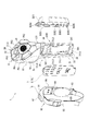
- FIG. 6 is a block diagram illustrating a configuration of the apparatus main body 2.
- the apparatus main body 2 includes a housing 3 constituting an exterior, an operation detection unit 4, light emitting units 5 ⁇ / b> R and 5 ⁇ / b> L and a switch SW disposed in the housing 3, and the housing 3.
- Each includes a microphone MC, a speaker SP, three vibration generators VB1 to VB3, a reaction force generator RD, and a controller 6.
- the operation detecting unit 4, the light emitting units 5R and 5L, the switch SW, the microphone MC, the speaker SP, and the vibration generating units VB1 to VB3 are connected to the control unit 6 through signal lines.
- the operation detection part 4 detects a user's operation.
- the operation detection unit 4 detects a pressing operation with a user's finger, a tilting operation of the finger, and a movement of a user's hand on which the operating device 1 is mounted.
- such an operation detection unit 4 includes a joystick JS, push keys PK1 to PK5, a trigger key TK, a pressure sensor PS, optical sensors LS1 to LS5, an acceleration sensor AS, and a gyro sensor GS.
- the present invention is not limited to this, and the operation detection unit 4 does not necessarily have all of them. For example, some of these may not be provided, and other detection units may be provided.
- the light emitting units 5L and 5R are arranged on the left side and the right side of the upper portion of the housing 3 and light up under the control of the control unit 6.
- the switch SW detects whether or not the mounting member 8 (8R) constituting the mounting member 7 is attached to the housing 3. Based on the detection result of the switch SW, the control unit 6 grasps the mounting position of the mounting member 7.
- the microphone MC outputs a sound signal corresponding to the sound outside the controller device 1 to the control unit 6.
- the speaker SP outputs a sound corresponding to the sound signal input from the control unit 6.
- Each of the vibration generating units VB1 to VB3 includes an actuator such as a motor that generates vibration, and is driven under the control of the control unit 6 to generate vibration.
- the reaction force generation unit RD includes an actuator such as a motor that is driven under the control of the control unit 6 and generates a reaction force against the user pressing the trigger key TK.
- the control unit 6 controls the operation of the apparatus main body 2 and is configured as a control device in which circuit elements such as arithmetic processing circuits are arranged.
- the control unit 6 includes an operation determination unit 61, a communication unit 62, a lighting control unit 63, and an operation control unit 64.
- the operation determination unit 61 determines the type of input operation performed on the apparatus main body 2 by the user based on the operation signal input from the operation detection unit 4.
- the communication unit 62 communicates with the information processing device PD and transmits / receives information to / from the information processing device PD.
- the communication unit 62 includes a communication method compliant with a wireless LAN communication standard such as IEEE802.11 (for example, IEEE802.11a / b / g / n / ac) and a short distance such as Bluetooth (registered trademark). It is configured by a module capable of communicating with the information processing device PD by at least one of communication methods compliant with the wireless communication standard.
- the communication unit 62 transmits operation information corresponding to the determination result by the operation determination unit 61 to the information processing apparatus PD. This operation information includes sound information corresponding to the sound detected by the microphone MC.
- the communication unit 62 uses the operating device 1 as a right operating device or a left operating device based on the on / off state of the switch SW. It is determined whether or not there is attachment information based on the determination result. Specifically, when it is determined that the switch SW is in the ON state, the communication unit 62 determines that the attachment member 8 is attached to the right side surface 3R and the operating device 1 is used as the right operating device. Then, the mounting information indicating the determination result is transmitted together with the operation information.
- the communication unit 62 determines that the attachment member 8 is attached to the left side surface 3L and the operating device 1 is used as the left operating device, The mounting information indicating the determination result is transmitted together with the operation information.
- the lighting control unit 63 controls lighting of the light emitting units 5L and 5R. Specifically, similarly to the communication unit 62, the lighting control unit 63 determines that the controller device 1 is used as the right controller device based on the on / off state of the switch SW. The light emitting unit 5R is lit in a predetermined color. In addition, when it is determined that the controller device 1 is used as the left controller device, the lighting controller 63 lights the light emitting unit 5L with a predetermined color.
- the lighting colors of the light emitting units 5L and 5R may be set in advance by the user as described above, or may be set according to information received from the information processing device PD via the communication unit 62, and are preset. May be the color.
- the operation controller 64 controls the operations of the speaker SP, the vibration generators VB1 to VB3, and the reaction force generator RD.
- the operation control unit 64 causes the speaker SP to output a sound corresponding to the sound information included in the reception information from the information processing device PD.
- the operation control unit 64 operates the vibration generating units VB1 to VB3 and the reaction force generating unit RD according to the drive signal included in the received information.
- the depth direction from the front surface 3A to the back surface 3B side of the housing 3 is the + Z direction (corresponding to the first direction of the present invention), and is orthogonal to the + Z direction and the bottom surface of the housing 3
- a height direction from 3D toward the top surface 3C is defined as a + Y direction (corresponding to a second direction of the present invention).
- a left-right direction that is orthogonal to each of the + Y direction and the + Z direction and is directed from the right side surface 3R of the housing 3 to the left side surface 3L is defined as a + X direction.
- the direction in which the fingers RH2 to RH5 extend in the state where the fingers of the right hand RH wearing the operating device 1 are extended is defined as + Z direction
- the direction orthogonal to the + Z direction and the direction in which the thumb RH1 extends is defined as + Y direction.
- the direction orthogonal to the + Z direction and + Y direction and from the right side to the left side is defined as the + X direction.
- the direction opposite to the + Z direction is taken as the ⁇ Z direction. The same applies to the ⁇ X direction and the ⁇ Y direction.
- [Case configuration] 7 to 11 are a right side view, a left side view, a front view, a rear view, and a bottom view showing the apparatus main body 2, respectively.
- the housing 3 is a synthetic resin housing that constitutes the exterior of the apparatus main body 2.
- the front surface 3A, the back surface 3B, the top surface 3C, the bottom surface 3D, the left side surface 3L, and the right side It has a surface 3R and is symmetrical with respect to a central plane CP (FIGS. 9 to 11) passing through the center in the + X direction and extending along the YZ plane, that is, left-right symmetrical.
- FIGS. 9 to 11 a central plane
- the housing 3 is formed in an inverted L shape when viewed from the + X direction side and the ⁇ X direction side. Specifically, the housing 3 has a shape that extends from the bottom surface 3D along the + Y direction and is inclined by approximately 60 degrees toward the + Z direction side with respect to the + Y direction.
- Such a housing 3 has a configuration in which a lower housing portion 30A and an upper housing portion 30B are integrally formed as shown in FIGS.
- the lower housing portion 30A is a columnar portion that forms a lower portion (a portion on the ⁇ Y direction side) of the housing 3 and is formed in a columnar shape having a substantially trapezoidal cross section in the YZ plane.
- the upper housing portion 30B is an inclined portion that constitutes the upper portion (the portion on the + Y direction side) of the housing 3 and is inclined in the + Z direction side while standing in the + Y direction from the lower housing portion 30A. .
- the lower housing portion 30A constitutes a front surface 3A and a bottom surface 3D, and lower portions of the back surface 3B, the left side surface 3L, and the right side surface 3R.
- the top surface 3C is configured by the upper housing portion 30B, and upper portions of the back surface 3B, the left side surface 3L, and the right side surface 3R are configured.
- the vertical dimension (the dimension in the + Y direction) of each of the lower casing part 30A and the upper casing part 30B is substantially the same, but the width dimension (the dimension along the + X direction) of the lower casing part 30A is the same as the upper casing. It is smaller than the width dimension of the body part 30B.
- the lower housing portion 30A is a columnar portion having a substantially trapezoidal cross section as described above.
- the width dimension (the dimension in the + X direction) on the front surface 3A side is substantially constant, the lower end portion (that is, the bottom surface 3D). It is formed in a shape in which the width dimension on the back surface 3B side becomes larger from the upper side toward the upper side (+ Y direction side).
- the shape of the lower housing portion 30A on the back surface 3B side is formed in an arc shape with the center in the width direction (+ X direction) protruding to the back side (+ Z direction side).
- the upper end (the end on the + Y direction side) on the front surface 3A side of the lower housing portion 30A is located at a position corresponding to the base of the thumb, and the back surface 3B The upper end on the side is located between the index finger and the middle finger. From these upper ends, the upper housing part 30B stands up.
- Mounting parts 31L1 and 31R1 described later are located in the left and right parts of the lower housing part 30A, and operation parts 34 and 35 described later are located in the part on the back surface 3B side.
- the part on the front surface 3A side of the upper housing part 30B rises upward while inclining from the upper end on the front surface 3A side of the lower housing part 30A to the back side (+ Z direction side), and the part on the back surface 3B side is the same.
- the lower housing portion 30A stands up from the upper end on the back surface 3B side while inclining from the upper end to the back side.
- the inclination angle (approximately 60 degrees in the present embodiment) of the part on the front surface 3A side (detailed second inclination part 322 described later) with respect to the + Y direction is the + Y direction of the part on the back surface 3B side. Is smaller than the inclination angle (approximately 70 degrees in this embodiment).
- the left side surface 3L and right side surface 3R side portions of the upper housing portion 30B are inclined upward from the upper end of the lower housing portion 30A to the left side (+ X direction side) and the right side ( ⁇ X direction side), respectively. Standing up.
- the surface facing the + Y direction side in the upper housing portion 30B is the top surface 3C.
- On the top surface 3C an operation unit 32 to be described later is located, and an operation to be described later is performed on a portion on the back surface 3B side.
- the part 33 is located.
- the casing 3 has a grip portion 31 and operation portions 32 to 35.
- the grip portion 31 is located at a portion that can be gripped by one hand of the user in the lower housing portion 30A.
- the grip portion 31 is a portion that can be gripped by the palm, ring finger, little finger, or the like in the lower housing portion 30A. The configuration of the grip portion 31 will be described in detail later.
- the operation unit 32 corresponds to a first operation unit of the present invention.
- the operation unit 32 is a portion that can be operated by the user's thumb (any one of the thumbs RH1 and LH1) in the upper housing unit 30B.
- the operation unit 32 is located on the top surface 3 ⁇ / b> C inclined in the + Z direction side with respect to the + Y direction in the housing 3.
- the operation unit 32 (that is, the top surface 3C) is formed in a substantially vertically long hexagonal shape when viewed from the front.
- Such an operation unit 32 includes a first inclined portion 321, a second inclined portion 322, and a third inclined portion 323 having different inclination angles toward the + Z direction with respect to the + Y direction.
- the first inclined portion 321 is a portion that is located closest to the ⁇ Y direction in the operation portion 32, and as shown in FIGS. 7 and 8, is inclined approximately 20 degrees toward the + Z direction with respect to the + Y direction.
- the first inclined portion 321 is inclined in a gently curved shape on the + Z direction side and on the ⁇ Y direction side from the center in the + X direction toward the + X direction side and the ⁇ X direction side.
- the ⁇ Z direction side portion of the first inclined portion 321 that is, a position corresponding to the proximal phalanx between the base of the thumb and the joint is on the + Z direction side of the thumb.
- An optical sensor LS1 for detecting the tilting position toward is located.
- the optical sensor LS1 emits detection light such as infrared light toward the outside, and detects the amount of detection light reflected by the thumb that is the detection target.
- detection light such as infrared light toward the outside
- Such an optical sensor LS1 is located on the + X direction side, the sensor light emission direction is inclined to the + X direction side with respect to the ⁇ Z direction, the ⁇ X direction side, and the detection light.
- the amount of light detected by these sensors is output to the control unit 6 by the optical sensor LS1, and the control unit 6 analyzes the position of the thumb based on the amount of light.
- the optical sensor LS1 is covered with a cover 3211 that can transmit the detection light.
- One of the two sensors constituting the optical sensor LS1 is arranged on the surface 321L inclined toward the + Z direction side and the ⁇ Y direction side toward the + X direction side.
- the sensor is disposed on a surface 321R that inclines toward the ⁇ Z direction side and toward the ⁇ Y direction side toward the ⁇ X direction side.
- a hole 3212 for outputting the sound from the speaker SP to the outside is formed in a portion on the + Y direction side in the first inclined portion 321.
- the 1st inclination part 321 does not need to incline in a curved surface shape as mentioned above, for example, has the some flat surface like the 3rd inclination part 323, and these flat surfaces are comprised. It may be inclined by a predetermined angle on the + Z direction side and on the ⁇ Y direction side.
- the second inclined portion 322 is a portion located on the + Y direction side from the first inclined portion 321 as shown in FIGS. 7 to 9, and as shown in FIGS. 7 and 8, in the + Z direction with respect to the + Y direction. It is inclined approximately 40 degrees to the side. Unlike the first inclined portion 321 and the third inclined portion 323, the second inclined portion 322 is formed substantially flat except for a formation position of a concave portion 3221 described later. That is, both ends of the second inclined portion 322 in the + X direction protrude on the ⁇ Z direction side and the + Y direction side as compared to both ends of the first inclined portion 321 and the third inclined portion 323 in the + X direction.
- the present invention is not limited to this, and the second inclined portion 322 may not be formed to be substantially flat.
- the + X direction side and ⁇ It may be inclined toward the + Z direction side and toward the ⁇ Y direction side toward the X direction side.
- the second inclined portion 322 is formed in a substantially inverted trapezoidal shape when viewed from the front, and the joystick JS is disposed at the center of the second inclined portion 322.
- the joystick JS has a shaft portion JS1 that is substantially orthogonal to the second inclined portion 322, and the shaft portion JS1 can be tilted forward, backward, left and right ( ⁇ Z direction and ⁇ X direction).
- the joystick JS detects the tilting direction of the shaft portion JS1 and outputs the detection result to the control unit 6.
- the entire joystick JS is configured to be able to protrude and retract with respect to the second inclined portion 322, and when an immersion operation is performed on the joystick JS, a push key (not shown) disposed on the back side of the joystick JS is pressed. Is done. By this push key, a pressing operation on the joystick JS is detected.
- a concave portion 3221 that is recessed inward is formed around the joystick JS, thereby securing the tilting amount of the shaft portion JS1.
- push keys PK1 and PK2 having parallelogram-shaped key tops are arranged at positions where the joystick JS is sandwiched between the left and right sides ( ⁇ X direction side) in the second inclined portion 322. These push keys PK1, PK2 output an operation signal corresponding to the input operation to the control unit 6.
- the third inclined portion 323 is a portion located further on the + Y direction side than the second inclined portion 322, and as shown in FIGS. 7 and 8, + Z with respect to the + Y direction. It is inclined approximately 60 degrees to the direction side.
- the third inclined portion 323 is formed in a trapezoidal shape when viewed from the front, and push keys PK3 to PK5 and light emitting portions 5L and 5R are arranged on the third inclined portion 323.
- the push key PK3 is disposed at the approximate center of the third inclined portion 323, and has a key top having a circular shape when viewed from the front.
- the push keys PK4 and PK5 are arranged at positions where the push key PK3 is sandwiched between the left and right sides ( ⁇ X direction side), and have a key top with a pentagonal shape when viewed from the front. These push keys PK3 to PK5 output an operation signal corresponding to the input operation to the control unit 6, similarly to the push keys PK1 and PK2.
- the third inclined portion 323 includes an inverted trapezoidal arrangement surface 3231 on which the push key PK3 is arranged, an inverted trapezoidal surface 3232 on which the push key PK4 is arranged, and the push key. It has an inverted trapezoidal surface 3233 on which PK5 is disposed.
- the surfaces 3231 to 3233 are flat surfaces, but the surfaces 3232 and 3233 are inclined in the same direction with respect to the surface 3231. More specifically, the surface 3232 is inclined toward the + Z direction side and toward the ⁇ Y direction side toward the + X direction, and the surface 3233 is inclined toward the ⁇ Z direction side and toward the ⁇ Y direction side toward the ⁇ X direction side. It is inclined to.
- the layout is such that the push keys PK3 to PK5 operated (pressed) at the tip portion of the thumb can be easily operated.
- the end portion on the + X direction side of the third inclined portion 323 may not be inclined as described above, and may be formed flat as a whole.
- the third inclined portion 323 may be formed in a curved surface like the first inclined portion 321.
- Each of the light emitting units 5L and 5R includes a solid light source such as an LED (Light Emitting Diode), and is disposed on the left and right at the upper end (the end on the + Y direction side) of the third inclined portion 323. Lighting of these light emitting units 5L and 5R is controlled by the control unit 6.
- the control unit 6 For example, when the mounting member 7 is attached to the right side surface 3 ⁇ / b> R, the operating device 1 is a right operating device, and thus the light emitting unit 5 ⁇ / b> R is turned on by the control unit 6.
- the controller device 1 is a left controller device, the light emitter 5L is turned on by the controller 6.
- the lighting colors of the light emitting units 5L and 5R are set by the control unit 6. Further, as shown in FIG. 9, a microphone hole 3234 is formed in a portion on the upper side (+ Y direction side) with respect to the push key PK3 in the third inclined portion 323, and the inside of the housing 3 corresponding to the microphone hole 3234 is formed.
- the microphone MC is disposed at the part.
- the operation unit 32 is symmetric with respect to the center plane CP, and the arrangement of the joystick JS, the push keys PK1 to PK5, and the optical sensor LS1 is also symmetric. That is, the joystick JS and the push key PK3 are disposed on the virtual line VL1 included in the center plane CP and along the vertical direction ( ⁇ Y direction) together with the hole 3212 and the microphone hole 3234.
- the push keys PK2 to PK5, the sensors of the optical sensor LS1, and the light emitting units 5L and 5R are arranged symmetrically with respect to the virtual line VL1.
- At least one of the operation units 33 to 35 corresponds to a second operation unit of the present invention.
- the operation unit 33 is located at a portion of the upper housing portion 30 ⁇ / b> B on the back surface 3 ⁇ / b> B side that can be operated by the user's index finger (either the index finger RH ⁇ b> 2 or LH ⁇ b> 2).
- the operation unit 33 is an upper portion of the back surface 3 ⁇ / b> B of the housing 3 (a portion inclined downward as it goes from the upper end of the top surface 3 ⁇ / b> C to the back side).
- the trigger key TK is disposed on the operation unit 33. Further, in addition to the optical sensor LS2 disposed in the housing 3 in accordance with the trigger key TK, the reaction force generator RD and the vibration generator VB1 (see FIG. 6) are disposed.
- the rotation axis along the + X direction is set at the end on the + Y direction side of the key top TK1, and the end on the ⁇ Y direction side of the key top TK1 around the rotation axis is ⁇ Z direction. Key to move along.
- the trigger key TK outputs an operation signal indicating that the key top TK1 has been input to the control unit 6. Similar to the optical sensor LS1, the optical sensor LS2 emits detection light toward the outside, and detects the amount of detection light reflected by the index finger that is a detection target. As shown in FIG.
- the optical sensor LS2 emits detection light to the outside and is incident through a translucent member TK2 fitted in a detection window TK3 formed substantially at the center of the key top TK1.
- the amount of detection light to be detected is detected.
- the light amount detected by the optical sensor LS2 is output to the control unit 6, and the control unit 6 analyzes the position of the index finger based on the light amount.
- the vibration generator VB1 transmits the generated vibration to the key top TK1. Thereby, vibration can be transmitted to the fingertip of the user's index finger touching the key top TK1.
- the reaction force generation unit RD generates a reaction force in the direction (+ Z direction) opposite to the direction in which the key top TK1 is immersed in the key top TK1 of the trigger key TK.
- the operation unit 34 is located on the upper side (+ Y direction side) on the back surface 3B side in the lower housing unit 30A. It is located in the part which can be operated by. Specifically, the operation unit 34 is located at a substantially central portion on the back surface 3 ⁇ / b> B of the housing 3 as shown in FIGS. 7, 8, and 10.
- the operation unit 34 is provided with the pressure sensor PS.
- the vibration sensor VB2 (see FIG. 6) is arranged in addition to the optical sensor LS3 at a position corresponding to the operation unit 34 in the housing 3.
- the pressure sensor PS detects the pressure acting on the housing 3 by the user's middle finger.
- the pressure sensor PS is covered with a cover member 341, and the pressure detected by the pressure sensor PS is a pressure acting on the cover member 341 by the middle finger.
- Such a pressure sensor PS outputs the detected pressure to the control unit 6.
- the optical sensor LS3 Similar to the optical sensors LS1 and LS2, the optical sensor LS3 emits detection light to the outside and detects the amount of detection light reflected by the middle finger that is a detection target. As shown in FIG. 10, the optical sensor LS3 emits detection light to the outside and is incident through a translucent member 342 fitted in a detection window 343 formed substantially at the center of the cover member 341. The amount of detection light to be detected is detected.
- the light amount detected by the optical sensor LS3 is output to the control unit 6, and the control unit 6 analyzes the position of the middle finger based on the light amount.
- the vibration generating unit VB2 transmits the generated vibration to the cover member 341. Thereby, vibration can be transmitted to the fingertip of the middle finger touching the cover member 341.
- the operation unit 35 is located in the lower part on the back surface 3B side in the lower housing part 30A, in other words, the user's ring finger (ring finger RH4, LH4) and the little finger (little finger RH5). , LH5).
- the operation unit 35 is a part on the lower side ( ⁇ Y direction side) on the back surface 3 ⁇ / b> B of the housing 3, in other words, the other part of the grip unit 31.
- the vibration VB3 is arranged in the department.
- the optical sensors LS4 and LS5 detect the amount of detection light reflected from the detection target, similar to the optical sensors LS1 to LS3. Specifically, the optical sensor LS4 detects the amount of detection light reflected by the ring finger that is the detection target, and the optical sensor LS5 detects the amount of detection light reflected by the little finger that is the detection target. And the light quantity detected by each optical sensor LS4, LS5 is output to the control part 6, and the control part 6 analyzes the position of a ring finger and a little finger based on the said light quantity.
- Such optical sensors LS4 and LS5 emit detection light through the translucent member 351 fitted in the detection window 352 formed in the operation unit 35, and receive incident detection light.
- the vibration generator VB3 has a motor that is larger than the motors of the vibration generators VB1 and VB2, and thereby generates vibrations greater than the vibrations generated by the vibration generators VB1 and VB2. Such a vibration generator VB3 vibrates the entire housing 3.
- the virtual line VL2 connecting the centers of the operation units 33 to 35 overlaps the virtual line VL1 when the housing 3 is viewed from the front 3A side or the back surface 3B side.
- the virtual line VL2 is included in the center plane CP. That is, the trigger key TK, the pressure sensor PS, and the optical sensors LS2 to LS5 are disposed on the center plane CP. More specifically, each of the operation parts 33 to 35 is symmetrical with respect to the center plane CP, and the arrangement of the trigger key TK, the pressure sensor PS, and the optical sensors LS2 to LS5 is the center plane CP ( It is symmetrical with respect to the virtual line VL2).
- the grip portion 31 is a portion on the ⁇ Y direction side in the housing 3 and is located in the lower housing portion 30A. As described above, the grip portion 31 is mainly formed by the palm, ring finger, and little finger. It is a part that can be gripped. As shown in FIG. 11, the grip portion 31 is formed in a columnar shape having a substantially trapezoidal cross section along the XZ plane, with a width dimension on the front surface 3A side (a dimension along the + X direction) smaller than a width dimension on the back surface 3B side.
- the center plane CP is the center of symmetry. As shown in FIGS.
- the attachment portion 31 ⁇ / b> L ⁇ b> 1 is located at a portion formed by the left side surface 3 ⁇ / b> L in such a grip portion 31, and the portion formed by the right side surface 3 ⁇ / b> R is shown in FIGS. As shown in FIG. 9, the attachment portion 31R1 is located.
- the mounting portion 31L1 When the operating device 1 is used as a left operating device, the mounting portion 31L1 is attached with a mounting member 8L constituting the mounting member 7, and when the operating device 1 is used as a right operating device, a battery is provided. It is a concave part to which case BCL (refer FIG. 14) is attached. As shown in FIGS. 8 and 9, the attachment portion 31L1 has a recess 31L2 in which a part of the battery is disposed when the battery case BCL is attached, and a terminal portion ( (Not shown).
- the attachment portion 31L1 has recesses 31L3 and 31L4.
- the recess 31L3 is located in the + Z direction side in the attachment portion 31L1, and extends along the + Y direction.
- the recess 31L4 is located in a portion on the + Y direction side in the attachment portion 31L1.
- two fixing portions 31L5 are located at both ends of the + Y direction side portion of the attachment portion 31L1, and one fixing portion 31L5 is located at the center of the attachment portion 31L1 on the ⁇ Y direction side portion. .
- Screws (not shown) for fixing the attachment member 8L are fixed to the fixing portions 31L5.
- the front surface 3A and the bottom surface 3D are formed with recesses 3A1 and 3D1 that connect the attachment portions 31L1 and 31R1.
- the attachment portion 31R1 is attached to the battery case BCR when the attachment member 8R constituting the mounting member 7 is attached when the operating device 1 is used as the right operating device, and when the operating device 1 is used as the left operating device. (Refer to FIG. 15) is a concave portion to which is attached.
- the mounting portion 31R1 has a substantially mirror-symmetrical structure with the mounting portion 31L1, and is similar to the terminal portions, the recessed portions 31L2 to 31L4 and the fixing portion 31L5, respectively (illustrated). (Not shown), and has concave portions 31R2 to 31R4 and a fixing portion 31R5.
- the switch SW that is turned on and off by being pressed by the mounting member 8R is disposed at the bottom of the recess 31R3.
- the switch SW may be provided on the attachment portion 31L1 (for example, the bottom of the recess 31L3).
- the control unit 6 determines which of the operation devices 1 is. You may detect and grasp
- FIG. 12 is an exploded perspective view showing the operating device 1 when the mounting member 7 is attached to the attachment portion 31R1 and the battery case BCL is attached to the attachment portion 31L1.
- FIG. 13 is an exploded perspective view of the operating device 1 when the mounting member 7 is attached to the attachment portion 31L1 and the battery case BCR is attached to the attachment portion 31R1.
- the mounting member 7 is attached to one of the mounting portions 31 ⁇ / b> R ⁇ b> 1 and 31 ⁇ / b> L ⁇ b> 1, and the mounting member 7 is mounted on one hand of the user, thereby operating the operation device. 1 is attached to the one hand.
- FIG. 14 is a perspective view of the battery case BCL for left-side attachment as viewed from the housing 3 side.
- the battery case BCL includes a storage part BCL1 located substantially at the center, and a left end part and a right end part when the battery case BCL is viewed so as to face the storage part BCR1.
- a battery (not shown) having a substantially rectangular parallelepiped shape is stored inside the storage portion BCL1.
- the upright portions BCL2 and BCL3 protrude toward the attachment portion 31L1.
- the standing portion BCL2 is inserted into the concave portion 31L3 in the attachment portion 31L1, and the standing portion BCL3 is fitted into the concave portion 3A1.
- the battery case BCL has a protruding portion BCL4 protruding upward from the upper end portion, and also has a protruding portion BCL5 protruding toward the attachment portion 31L1 from the lower end portion.
- the protrusion BCL4 is inserted into the recess 31L4, and the protrusion BCL5 is fitted into the recess 3D1.
- the protruding portion BCL5 is formed with two holes BCL6 through which screws (not shown) for fixing the battery case BCL to the attachment portion 31L1 are inserted.
- FIG. 15 is a perspective view of the battery case BCR for right side mounting as viewed from the housing 3 side.
- the battery case BCR has a substantially mirror-symmetric structure with respect to the battery case BCL.
- the battery case BCR has a storage part BCR1 in which the battery is stored in the center, as well as rising parts BCR2, BCR3 similar to the rising parts BCL2, BCL3 and the protruding parts BCL4, BCL5, respectively.
- the protrusions BCR4 and BCR5 have two holes BCR6 similar to the two holes BCL6.
- the mounting member 7 mounts the apparatus main body 2 on the left hand LH or the right hand RH of the user.
- the mounting member 7 includes a mounting member 8 (8L, 8R) and a band member 9, and the usage state of the operating device 1 (used as a right operating device or a left operating device). It is attached to one of the left and right attachment portions 31L1, 31R1 depending on whether it is used as a device.
- the attachment member 8L is used when the attachment member 7 is attached to the attachment portion 31L1, and when the attachment member 7 is attached to the attachment portion 31R1, as shown in FIG.
- a mounting member 8R is used.
- FIG. 17 is a view of the attachment member 8L as viewed from the housing 3 side.
- the attachment member 8L attaches the attachment member 7 to the housing 3 by being attached to the attachment portion 31L1 in a state where the band member 9 is fixed.
- the attachment member 8L is configured to be capable of adjusting the attachment position of the band member 9 to the attachment member 8L, and is thereby configured to be able to adjust the position of the apparatus main body 2 in the left hand LH to which the band member 9 is attached. Yes.
- the mounting member 8L is a metal plate-like body formed in a substantially rectangular shape corresponding to the concave mounting portion 31L1, and is fitted into the mounting portion 31L1. Can be attached.
- the mounting member 8L is erected in the out-of-plane direction at one end in the short direction, and an upright part 8L1 that extends along the longitudinal direction, and a protruding part that projects in the out-of-plane direction at one end and the other end in the longitudinal direction.
- the standing portion 8L1 is formed at a position corresponding to the concave portion 31L3, similarly to the standing portion BCL2.
- the standing portion 8L1 rises from the end of the mounting member 8L toward the mounting portion 31L1 and is inserted into the concave portion 31L3.
- the protruding portions 8L2 and 8L3 are formed at positions corresponding to the recessed portion 31L4 of the mounting portion 31L1 and the recessed portion 3D1 of the bottom surface 3D, similarly to the protruding portions BCL4 and BCL5.
- the protrusion 8L2 is inserted into the recess 31L4, and the protrusion 8L3 is fitted into the recess 3D1.
- the protrusion 8L3 has two holes 8L4 through which screws (not shown) for fixing the attachment member 8L to the attachment 31L1 are inserted.
- the position adjusting portions 8L5 to 8L8 are portions for adjusting the attachment position of the band member 9, and further, are portions for adjusting the position of the apparatus main body 2 in the left hand LH.
- Each of these position adjusting portions 8L5 to 8L8 has four groove portions.
- the position adjusting unit 8L5 has groove portions 8L51 to 8L54
- the position adjusting portion 8L6 has groove portions 8L61 to 8L64.
- the position adjustment unit 8L7 has groove portions 8L71 to 8L74
- the position adjustment portion 8L8 has groove portions 8L81 to 8L84.
- groove portions 8L51 to 8L54, 8L61 to 8L64, 8L71 to 8L74, 8L81 to 8L84 are groove portions through which the shaft portion of the screw for fixing the attachment member 8L to the band member 9 is inserted, and these groove portions 8L51 to 8L54, 8L61 to 8L64, The groove widths of 8L71 to 8L74 and 8L81 to 8L84 are set to groove widths provided with a predetermined clearance in the diameter of the shaft portion of the screw.
- the groove portions 8L52, 8L62, 8L72, and 8L82 correspond to the first groove portion of the present invention
- the other groove portions correspond to the second groove portion of the present invention.
- the groove portions 8L52, 8L62, 8L72, and 8L82 have a configuration in which a plurality of circular hole portions are arranged adjacent to each other in series, and these hole portions are connected to each other.
- each of the groove portions 8L52 and 8L62 is formed by five hole portions
- each of the groove portions 8L72 and 8L82 is formed by four hole portions.
- the internal diameter of these holes is set to the dimension which the shaft part of the said screw penetrates. For this reason, it is suppressed that the axial part inserted in one hole part enters into the other hole part adjacent to the said hole part.
- the groove positions 8L51 to 8L54, 8L61 to 8L64, 8L71 to 8L74, and 8L81 to 8L84 constituting the position adjusting portions 8L5 to 8L8 are the same in the same position adjusting portion.
- the groove directions of the groove portions 8L51 to 8L54 are the same, and the groove directions of the groove portions 8L71 to 8L74 are the same.
- the groove directions of the position adjusting portions 8L5 to 8L8 are radial directions centered on a predetermined center point CL.
- each of the groove directions DL1 to D4 is a direction extending radially from the center point CL.
- the groove directions DL1 to DL4 are inclined with respect to the + Y direction, respectively.
- the groove directions DL1 and DL2 of the position adjusting portions 8L5 and 8L6 positioned on the ⁇ Z direction side are inclined with respect to the + Y direction so as to be inclined toward the ⁇ Z direction side toward the + Y direction side.
- the crossing angle between the groove direction DL1 and the + Y direction is larger than the crossing angle between the groove direction DL2 and the + Y direction.
- the groove directions DL3 and DL4 of the position adjusting portions 8L7 and 8L8 located on the + Z direction side are inclined with respect to the + Y direction so as to be inclined toward the + Z direction side toward the + Y direction side.
- the intersection angle with the + Y direction is larger than the intersection angle between the groove direction DL3 and the + Y direction.
- the crossing angles of the groove directions DL1 and DL2, the crossing angles of the groove directions DL2 and DL3, and the crossing angles of the groove directions DL3 and DL4 are approximately 4 degrees, respectively.
- the intersection angle can be changed as appropriate. At least one intersection angle may be different from other intersection angles.
- the center point CL may not be located outside the attachment member 8L, and may be on the attachment member 8L.
- the groove directions DL1 to DL4 may not intersect at one central point CL.
- each of the groove directions DL1, DL2 intersects at a first center point
- the groove directions DL3, DL4 intersect at a second center point set at a position different from the first center point.
- a position adjustment unit may be formed.
- FIG. 18 is a view of the attachment member 8R as viewed from the housing 3 side.
- the attachment member 8 ⁇ / b> R attaches the attachment member 7 to the housing 3 by being fitted and fixed to the attachment portion 31 ⁇ / b> R ⁇ b> 1 in a state where the band member 9 is fixed.
- the mounting member 8R is a metal plate-like body having a substantially mirror-symmetrical structure with the mounting member 8L, and as shown in FIG. Similar to the adjustment portions 8L5 to 8L8, it has an upright portion 8R1, protrusions 8R2 and 8R3, a hole portion 8R4, and four position adjustment portions 8R5 to 8R8. Note that a protruding portion 8R11 for inputting the switch SW disposed at the bottom of the concave portion 31R3 protrudes from the standing portion 8R1.
- the position adjusting portion 8R5 is formed along the groove direction DR1 extending from the center point CR set outside the mounting member 8R and at a position on the ⁇ Y direction side with respect to the mounting member 8R.
- the position adjusting unit 8R7 has four groove portions 8R71 to 8R74 formed along the groove direction DR3 extending from the center point CR, and the position adjusting unit 8R8 is a groove extending from the center point CR.
- the groove portions 8R52, 8R62, 8R72, 8R82 have a configuration in which a plurality of circular hole portions are arranged adjacent to each other in series, similar to the groove portions 8L52, 8L62, 8L72, 8L82.
- the same position adjustment unit is connected to each other.
- the groove directions DR1 and DR2 of the position adjusting portions 8R5 and 8R6 located on the ⁇ Z direction side are inclined toward the ⁇ Z direction side toward the + Y direction side, and the crossing angle between the groove direction DR1 and the + Y direction is More than the crossing angle between the groove direction DR2 and the + Y direction.
- the groove directions DR3 and DR4 of the position adjusting portions 8R7 and 8R8 located on the + Z direction side are inclined toward the + Z direction side toward the + Y direction side, and the crossing angle between the groove direction DR4 and the + Y direction is the groove It is larger than the crossing angle between the direction DR3 and the + Y direction.
- the crossing angles of the groove directions DR1 and DR2, the crossing angles of the groove directions DR2 and DR3, and the crossing angles of the groove directions DR3 and DR4 are each about 4 degrees. That is, the groove directions DR1 to DR4 extend radially from the center point CR in the same manner as described above.
- the band member 9 is attached to the groove portion of any one of the position adjustment portions 8R5 to 8R8. Further, when the attachment member 8L is used, the band member 9 is attached to the groove portion of any one of the position adjustment portions 8L5 to 8L8.
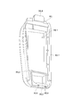
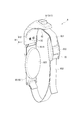
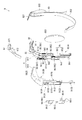
- FIG. 19 is a perspective view showing the band member 9 in an expanded state
- FIG. 20 is a perspective view showing the band member 9 in a reduced state. 2 and 3, the band member 9 passes between the base of the user's thumb and the base of the index finger and between the base of the little finger and the wrist so as to connect the palm and the back of the hand. It is a member that is wound and attached to one hand.
- the band member 9 is deformed from the extended state shown in FIG. 19 to the reduced state shown in FIG. 20 to reduce the circumferential dimension (inner peripheral dimension) of the band member 9, thereby mounting the mounting member 7. In this case, it has a configuration capable of performing additional tightening.
- the optical sensors LS1 to LS5 detect the position of each finger, it is assumed that all fingers are separated from the operating device 1, and the acceleration sensor AS and the gyro sensor. Since the GS detects the movement of one hand of the user wearing the operation device 1, it is necessary to attach the operation device 1 to the one hand without wobbling. For this reason, since the band member 9 is configured to be able to perform tightening, the degree of adhesion of the operating device 1 to one hand is increased.
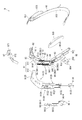
- FIGS. 21 and 22 are exploded perspective views showing the band member 9 in the extended state
- FIGS. 23 and 24 are perspective views showing the band member 9 in the contracted state
- 21 and 23 are exploded perspective views of the band member 9 as viewed from the side attached to the housing 3
- FIGS. 22 and 24 show the band member from the side opposite to the side attached to the housing 3.
- FIG. 21 to 24 such a band member 9 includes a main body member 91, a telescopic member 92, a strip member 93, a slide member 94, a link member 95, a locking member 96, an operation member 97, and an urging member. 98.
- the slide member 94 and the link member 95 constitute the slide mechanism of the present invention.
- the main body member 91 is a substantially L-shaped member that is disposed at the base of the thumb when the mounting member 7 is mounted on one hand.
- the main body member 91 is configured by combining a first main body portion 911 and a second main body portion 912. A part of each of the slide member 94 and the operation member 97 and the urging member 98 are arranged so as to be sandwiched between the main body portions 911 and 912.
- the first main body portion 911 has two attachment portions 9111 to which the elastic member 92 is attached on one end side, and two moving bodies 941 of the slide member 94 are arranged on the other end side.
- a recess 9112 is provided.
- the bottoms of these recesses 9112 function as a guide surface that guides the slide of the movable body 941 in the vertical direction ( ⁇ Y direction).
- the first main body 911 has a hole 9113 through which a screw SC fixed to the second main body 912 is inserted at a position between the pair of recesses 9112 and a position on the one end side.
- a positioning projection 9121 and three fixing portions 9122 that are located on the same straight line are provided on a surface 912A of the second main body portion 912 opposite to the first main body portion 911 side.
- the positioning projections 9121 and the three fixing portions 9122 are used when the band member 9 is attached to the attachment members 8L and 8R, as will be described in detail later.
- fixed part 9122 is comprised by the insert nut in this embodiment.
- the second main body 912 has a recess 9123 in which the locking member 96 is disposed on the surface 912 ⁇ / b> A, and an opening 9124 connected to the recess 9123.
- the opening 9124 is inserted with a connecting portion 972 connected to the locking piece 961 disposed in the recess 9123.
- an opening 9125 from which the operation button 971 is exposed is formed on one end side of the second main body 912.
- the second main body portion 912 includes three fixing portions 9126, two arrangement portions 9127, and one arrangement portion 9128 on the surface 912B on the first main body portion 911 side. Screws SC inserted through the hole 9113 are fixed to the three fixing portions 9126.
- positioning parts 9127 are the site
- One arrangement portion 9128 is located at a lower part of the surface 912B, and is a part where the second urging member 982 of the urging member 98 is arranged along the vertical direction.
- the second main body 912 includes a hole 9129 that passes through the second main body 912 along the short direction (width direction) of the second main body 912 and an attachment portion. Part 9130.
- the rod portion 942 of the slide member 94 is inserted through the hole portion 9129 along the short direction. Since the slide member 94 is slidable in the vertical direction, the hole 9129 is also a hole that is long in the vertical direction.
- the second link member 952 of the link member 95 is rotatably attached to the attachment portion 9130.
- the elastic member 92 is attached to the attachment portion 9111 of the first main body portion 911.
- the elastic member 92 is composed of a band having elasticity such as rubber, and the free end when attached to the attachment portion 9111 is connected to the first belt-like portion 931 of the belt-like member 93.
- the expansion / contraction member 92 has a function of adjusting the inner peripheral dimension of the band member 9 by expanding and contracting and improving the adhesion of the mounting member 7 to one hand.
- the band-shaped member 93 is disposed on the back of the hand when the band member 9 is attached to one hand.
- the belt-like member 93 includes a first belt-like portion 931 coupled to the expansion and contraction member 92, a second belt-like portion 932 connected to the first link member 951 of the link member 95, the first belt-like portion 931 and the second belt-like portion 931. And a buckle 933 for connecting the belt-like portion 932.
- the slide member 94 is attached to the main body member 91 so as to be slidable in the vertical direction.
- the slide member 94 has two moving bodies 941 and one rod-like portion 942.
- the two moving bodies 941 are each formed in a substantially L shape in cross-sectional view, and are housed in the two recesses 9112 (see FIGS. 21 and 23).
- the rod-like portion 942 connects two moving bodies 941.
- the rod-like portion 942 is inserted through the hole 9129, thereby restricting the slide member 94 from dropping from the main body member 91 and guiding the slide along the vertical direction of the slide member 94.
- the link member 95 slides the slide member 94 along the vertical direction.
- the link member 95 includes a first link member 951 and a second link member 952.
- One end of the first link member 951 is rotatably supported by the rod-like portion 942 of the slide member 94.
- the other end of the first link member 951 is connected to the end opposite to the buckle 933 side of the second strip 932 of the strip member 93.
- the surface of the first link member 951 opposite to the second main body portion 912 is a flat surface, which is a contact surface 951A on which the palm of the user can contact.
- the contact surface 951A is provided with a bulging member 955 having a shape corresponding to the concave portion located in the center of the palm.
- the second link member 952 has approximately half the size of the first link member 951, and one end is rotatably supported by a rod-like portion 953 suspended from a substantially central portion of the first link member 951. The end is rotatably supported by the attachment portion 9130 of the second main body portion 912 by the rod-like portion 954.
- the second link member 952 protrudes from the second main body portion 912 so as to be inclined with respect to the second main body portion 912, and the first link member 951 is inclined downward while being inclined with respect to the second main body portion 912.
- the slide member 94 to which the first link member 951 is connected is slid downward.
- the locking member 96 maintains the state in which the slide member 94 is slid upward, that is, the contracted state of the band member 9, by locking the rod-shaped portion 953.
- the locking member 96 includes a locking piece 961 that is slidable in the vertical direction in the concave portion 9123 of the second main body portion 912, and a fixing portion 962.
- the locking piece 961 has a pair of locking claws 9611 that locks the rod-shaped portion 953 at the lower end portion, and also has long holes 9612 and 9613 and a pair of screw holes 9614.
- the pair of locking claws 9611 has a rod-like portion 953 that is a connection portion between the link members 951 and 952. Lock.
- the edge part by the side of the 1st link member 951 in the said pair of latching claw 9611 inclines in the direction spaced apart from the said 1st link member 951 as it goes below, Thereby, a pair of latching claw 9611 is carried out.
- the locking piece 961 slides upward, and then slides downward to lock the rod-shaped portion 953.
- the positioning projection 9121 and the fixing portion 9122 positioned in the recess 9123 are inserted through the long holes 9612 and 9613.
- a screw SC inserted through the fixing portion 962 is fixed to the screw hole 9614.
- the end of the locking piece 961 opposite to the locking claw 9611 side is connected to the operation member 97.
- the fixing portion 962 is disposed on the opposite side of the locking piece 961 across the second main body portion 912, and the screw SC inserted through the fixing portion 962 is fixed to the screw hole 9614, whereby the locking piece 961. Fixed to. As shown in FIGS. 21 and 23, the other end of the second urging member 982 whose one end is in contact with the upper end surface of the arrangement portion 9128 (see FIGS. 22 and 24) contacts the fixing portion 962. . Accordingly, the locking piece 961 to which the fixing portion 962 is fixed is urged downward, that is, in a direction in which the locking piece 961 locks the rod-shaped portion 953.
- the operation member 97 is operated when the band member 9 is extended and removed from one hand, and the locking piece 961 is slid upward to lock the rod-like portion 953 by the locking piece 961, that is, the band member 9 Cancel the reduced state.
- the operation member 97 includes an operation button 971 and a connecting portion 972.
- the operation button 971 is exposed to the outside through the opening 9125.
- the operation button 971 is supported in the main body member 91 so that the end portion on the connecting portion 972 side can rotate.
- the connecting portion 972 is connected to the operation button 971 on one end side and is connected to the locking piece 961 on the other end side.
- the urging member 98 includes two first urging members 981 and one second urging member 982, and the first urging member 981 and the second urging member 982 are provided.
- the biasing member 982 is constituted by a compression coil spring.
- the two first urging members 981 are respectively arranged in the arrangement portion 9127 along the vertical direction. One end of these first urging members 981 is in contact with the upper surface of the inner surface of the arrangement portion 9127, and the other end is in contact with the moving body 941. Therefore, each first urging member 981 urges each moving body 941 downward.
- the first biasing member 981 biases the slide member 94 so that the band member 9 is in the extended state.
- the number of the first urging members 981 is not limited to 2, and may be 1 or 3 or more.
- One second urging member 982 is arranged along the vertical direction in the arrangement portion 9128 (see FIGS. 22 and 24). One end of the second biasing member 982 is in contact with the upper surface of the inner surface of the arrangement portion 9128, and the other end is in contact with the fixing portion 962 of the locking member 96. For this reason, as described above, the second urging member 982 urges the locking member 96 downward.
- the number of the second urging members 982 is not limited to 1, and may be 2 or more.
- FIG. 25 is a side view showing the band member 9 in an expanded state
- FIG. 26 is a side view showing the band member 9 in a reduced state.
- the band member 9 can be tightened even after the length of the band-shaped member 93 is adjusted by sliding the slide member 94 upward from the extended position. Specifically, when the extended band member 9 shown in FIG. 25 is attached to one hand, the link member 95 is rotated along the second main body portion 912 and the slide member 94 is slid upward. As shown in FIG. 26, the band member 9 is in a contracted state.
- the dimension L2 between the lower end 9127A of the arrangement portion 9127 and the rod-shaped portion 942 of the slide member 94 is larger than the dimension L1 between the lower end 9127A and the rod-shaped portion 942 in the expanded state (see FIG. 25). Get smaller.
- the contact surface 951A is pressed toward the second main body portion 912 to rotate the link members 951 and 952 and slide the slide member 94 upward.
- the band member 9 can be tightened by (L1-L2). Therefore, it is possible to increase the degree of adhesion of the band member 9 and eventually the operating device 1 to one hand.
- the operation button 971 on the operation member 97 is pressed, the locking of the rod-shaped portion 953 by the locking piece 961 is released, and the sliding member 94 is moved downward by the biasing force of the first biasing member 981. And the band member 9 is extended. Thereby, the band member 9 and by extension, the operating device 1 can be easily removed from one hand.
- FIG. 27 is a diagram for explaining the size of each hand of the user who wears the operating device 1
- FIG. 28 is a diagram for explaining the position adjustment range of the device main body 2 with respect to the attachment member 8 (8R).
- the band member 9 is attached to the attachment member 8 (8R, 8L)
- the attachment member 7 is attached to the attachment portions 31R1, 31L1, so that the attachment member 7 is attached to the casing 3 of the apparatus main body 2. It is possible to attach the operating device 1 to one hand of the user.
- FIG. 1 is a diagram for explaining the size of each hand of the user who wears the operating device 1
- FIG. 28 is a diagram for explaining the position adjustment range of the device main body 2 with respect to the attachment member 8 (8R).
- the band member 9 is attached to the attachment member 8 (8R, 8L)
- the attachment member 7 is attached to the attachment portions 31R1, 31L1, so that the attachment member 7 is attached to the casing 3 of the apparatus main body 2. It is possible to attach the operating device 1 to one hand of the
- the apparatus main body 2 with respect to the mounting member 7 (mounting member 8).
- the positions of the operation units 32 to 35 can be arranged at positions corresponding to the respective fingers, and the operation device 1 can be easily operated.
- the position adjustment range of the apparatus main body 2 (housing 3) with respect to the mounting member 7 as described above, and the position adjustment range in which the difference in the size of one hand between men and women of the target age as a user can be allowed is as shown in FIG. Further, based on the case where the operating device 1 is attached to one hand of an average size, it is 12 mm in the front-rear direction ( ⁇ Z direction) and 6 mm in the vertical direction ( ⁇ Y direction). It was found by the person.
- the apparatus main body 2 is attached to the attachment portions 31R1 and 31L1.
- the attachment position of the attachment member 8 (8R, 8L) to be attached and the band member 9 attached to one hand can be adjusted.
- the positioning protrusion 9121 of the second main body portion 912 of the band member 9 among the four position adjusting portions is inserted, and the screw fixed to the fixing portion 9122 is inserted.
- the position adjustment part is selected according to the size of one hand, and the position of the hole into which the positioning protrusion 9121 is inserted is further selected, so that the attachment position can be adjusted.
- FIGS. 29 to 32 are views showing the relative positions of the attachment member 8R and the band member 9.
- the band member 9 is attached to the attachment member 8R by using the position adjustment portion 8R8 located closest to the + Z direction in the attachment member 8R, so that the apparatus main body 2 can be moved within the position adjustment range. It can be arranged on the most ⁇ Z direction side. Further, the position of the band member 9 in the ⁇ Y direction with respect to the mounting member 8R is adjusted by selecting the hole into which the positioning protrusion 9121 (see FIGS. 21 and 23) is inserted from the four holes of the groove 8R82. it can. Further, as shown in FIGS.
- the band member 9 is attached to the attachment member 8R by using the position adjustment portion 8R7 or the position adjustment portion 8R6 located on the ⁇ Z direction side of the position adjustment portion 8R8 in the attachment member 8R.
- the apparatus main body 2 can be arranged on the + Z direction side as compared with the case where the position adjustment unit 8R8 is used.
- the band member 9 in the ⁇ Y direction with respect to the mounting member 8R is selected. The position can be adjusted.
- the band member 9 is attached to the attachment member 8R by using the position adjustment portion 8R5 located closest to the ⁇ Z direction in the attachment member 8R, so that the apparatus main body 2 can be moved within the adjustment range. It can arrange
- the position adjustment portion used when attaching the band member 9 to the attachment member 8R is selected from the position adjustment portions 8R5 to 8R8, and the hole portion into which the positioning protrusion 9121 is inserted is the groove portions 8R52, 8R62, 8R72, By selecting from a plurality of holes of 8R82, the position of the apparatus body 2 can be adjusted in the right hand RH with the band member 9 attached. The same applies when the band member 9 is attached to the attachment member 8L.
- the groove directions DR1 ⁇ DR4 and the groove directions DL1 to DL4 of the position adjusting units 8L5 to 8L8 may be parallel to the + Y direction, respectively.
- the groove directions DR1 to DR4 are directions extending radially from the center point CR, and are inclined with respect to each other.
- the groove directions DL1 to DL4 are also radially extending from the center point CL, and are inclined with respect to each other.
- the position of the operation unit 32 (joystick JS) is changed to the center point CR, without greatly changing the position of the operation unit 33 (trigger key TK) with one hand having a different size for each user.
- the joystick JS and push keys PK1 to PK5 of the operation unit 32 are independent of the size of one hand on which the operation device 1 is mounted. This is because the operation unit 32 is arranged at a position where it can be easily operated with the thumb.
- the information processing device PD may notify the user of the position adjustment unit and the hole to be used by the image display device DS or the like.
- the housing 3 is configured symmetrically about the center plane CP.
- the joystick JS, the push key PK3, the trigger key TK, and the optical sensors LS2 to LS4 disposed in the housing 3 are included in the center plane CP as shown in FIGS. 9 and 10, and Arranged on virtual lines VL1 and VL2 along the + Y direction.
- the push keys PK1, PK4 and the push keys PK2, PK5 are arranged symmetrically about the virtual line VL1 as shown in FIG.
- the two sensors constituting the optical sensor LS1 are also arranged symmetrically about the virtual line VL1. That is, not only the shape of the housing 3 but also the arrangement of each component of the operation detection unit 4, the apparatus main body 2 is configured to be bilaterally symmetric about the center plane CP.
- FIG. 33 is a cross-sectional view along the XZ plane at the center of the first link member 951 of the operating device 1 in which the mounting member 7 is attached to each of the left and right attachment portions 31R1 and 31L1.
- the attachment member 7 is not attached to the left and right attachment portions 31R1 and 31L1 during normal use of the operating device 1, but in order to explain the left-right symmetry of the operating device 1, FIG. A state in which the mounting member 7 is attached to the attachment portions 31R1, 31L1 is illustrated.
- the apparatus main body 2 and the left and right attachment members 7 are symmetrical with respect to the center plane CP.
- the contact surface 951A of the first link member 951 is a contact surface with which the palm of the user can contact, and the contact surface 951A when the mounting member 7 is in the contracted state.
- the extension planes EPL and EPR that extend are inclined at the same angle with respect to the center plane CP.
- the extension plane EPL intersects the center plane CP at an angle ⁇ 1 at an intersection CT located on the ⁇ Z direction side with respect to the apparatus main body 2, and the extension plane EPR has an angle with respect to the center plane CP.
- These angles ⁇ 1 and ⁇ 2 are the same angle.
- the center plane CP is a plane including a bisector of the intersection angle between the extension planes EPL and EPR.
- the extension planes EPL and EPR of the contact surface 951A of the mounting member 7 attached to either the left or right side of the housing 3 move toward the center plane CP in a direction away from the center plane CP toward the + Z direction.
- the shape of the housing 3 follows the shape of one hand (left hand LH or right hand RH) when the operating device 1 is gripped. Therefore, it is possible to easily grasp the controller device 1 with the one hand. Since the shape of the housing 3 and the arrangement of the components of the operation detection unit 4 are bilaterally symmetric, even when the operation device 1 is attached to either the right hand RH or the left hand LH, the operation device 1 is gripped. In addition to making it easier to operate, the operation device 1 can be made easier to operate. In the present embodiment, the angles ⁇ 1 and ⁇ 2 are each set to 20 degrees.
- the extension plane EPL is attached to a virtual plane (an attachment surface to which the attachment member 8L is attached in the housing 3) connecting the end edges of the attachment portion 31L1 formed in a concave shape on the left side surface 3L, and the attachment portion 31L1. Further, it is parallel to a virtual plane (an attachment surface to which the band member 9 is attached in the housing 3 to which the attachment member 8L is attached) obtained by extending the outer surface of the attachment member 8L.
- the extension plane EPR is a virtual plane (an attachment surface of the housing 3 to which the attachment member 8R is attached in the housing 3) connecting the edge of the attachment portion 31R1 formed in a concave shape on the right side surface 3R, and the attachment It is parallel to a virtual plane (an attachment surface to which the band member 9 is attached in the housing 3 to which the attachment member 8R is attached) obtained by extending the outer surface of the attachment member 8R attached to the portion 31R1.
- the respective virtual planes (mounting surfaces) are inclined in the direction away from the center plane CP toward the + Z direction side, so that the extended planes EPL and EPR of the contact surface 951A are as described above. Can be reliably tilted.
- the housing 3 can be easily gripped. Can be played.
- the operation device 1 has the following effects.
- the operating device 1 is located on the front 3A side and can be operated by the thumbs RH1 and LH1 of the right hand RH or the left hand LH, and the fingers RH2 to RH5 and LH2 other than the thumbs RH1 and LH1 are located on the back 3B side.
- Operation sections 33 to 35 that can be operated by LH5, and an abutment surface 951A on which the palm of the right hand RH or the left hand LH abuts.
- the extension plane EPR of the contact surface 951A when the mounting member 7 is attached to the attachment portion 31R1 and the extension plane EPL of the contact surface 951A when the attachment member 7 is attached to the attachment portion 31L1 are the front surface.
- a virtual surface defined by a + Z direction that is a first direction from the 3A side toward the back surface 3B side and a + Y direction that is orthogonal to the + Z direction and is a second direction from the bottom surface 3D side toward the top surface 3C side Is inclined in a direction away from the center plane CP as it goes toward the + Z direction.
- gripped with the user's one hand in the operating device 1 can be made to follow the shape of the one hand at the time of holding the said site
- the operating device 1 When the mounting member 7 is attached to the attachment portion 31R1, the operating device 1 has a contact surface 951A located on the right side with respect to the center plane CP, and the attachment member 7 is attached to the attachment portion 31L1.
- the first contact surface in the present invention corresponds to the second contact surface in the present invention.
- the extension planes EPR and EPL of the contact surface 951A are inclined in a direction away from the center plane CP toward the + Z direction. According to this, the controller device 1 can be mounted and gripped independently on each of the right hand RH and the left hand LH. Therefore, the operating device 1 that can be used with each of the right hand RH and the left hand LH can be configured.
- a housing 3 provided in the operating device 1 includes the operating units 32 to 35, and a central plane CP as a virtual plane according to the present invention includes a bisector of an intersection angle of the extended planes EPL and EPR. It is a central plane of the housing 3.
- the housing 3 can have a left-right symmetrical structure, and each configuration of the operation units 32 to 35 can be arranged left-right symmetrically. Therefore, the controller 1 can be configured as a left / right controller, and there is no need to manufacture a controller for the right and a controller for the left. Therefore, the manufacturing cost of the controller 1 can be reduced, and the versatility of the controller 1 can be increased. Can be increased.
- the intersection angle between the extension plane EPL and the center plane CP is 20 degrees
- the intersection angle between the extension plane EPR and the center plane CP is 20 degrees.
- the intersection angle between the extension planes EPL and EPR. Is an acute angle of 40 degrees. That is, the crossing angle between the extended surface of the contact surface 951A of the mounting member 7 disposed on the left and right sides and the other side surface is an acute angle of 40 degrees. According to this, compared with the case where these extension planes EPL and EPR intersect at an obtuse angle, it becomes easier to turn the finger around the operating device 1, so that the operating device 1 can be easily held with the left and right hands. Therefore, the operation device 1 can be easily operated with the one hand.
- the operating device 1 includes a housing 3 having the operation units 32 to 35 and a mounting member 7 for mounting the housing 3 on one hand of a user.
- the mounting member 7 includes an attachment member 8 (8L, 8R) attached to the housing 3, and a band member 9 attached to the attachment member 8 and wound around the palm of the right hand RH or the left hand LH and the back of the hand.
- the casing 3 device main body 2 having the operation units 32 to 35 is maintained in one hand of the user by the band member 9. it can. Therefore, the convenience of the controller device 1 can be improved, and the sensors LS1 to LS5 can reliably detect the positions of the fingers RH1 to RH5 and LH1 to LH5.
- the attachment member 8R attached to the attachment part 31R1 of the housing 3 has position adjustment parts 8R5 to 8R8 each capable of adjusting the position of the band member 9 in the + Y direction, and these position adjustment parts 8R5 to 8R8 is arranged in parallel along the + Z direction which is the depth direction of the controller device 1, respectively.
- the attachment member 8L attached to the attachment part 31L1 of the housing 3 has position adjustment parts 8L5 to 8L8 that can adjust the position of the band member 9 in the + Y direction, respectively.
- These position adjustment parts 8L5 to 8L8 are Are arranged in parallel along the + Z direction. According to this, the position of the attachment members 8L and 8R in one hand to which the band member 9 is attached can be adjusted.
- the position of the housing 3 (device main body 2) in the one hand can be adjusted. Therefore, the position of the apparatus main body 2 can be adjusted according to the size of one hand of the user, and the operation units 32 to 35 can be arranged at positions that are easy for the user to operate, so that the operation apparatus 1 can be operated easily.
- the band member 9 includes a positioning projection 9121 protruding toward the mounting members 8L and 8R, and three fixing portions 9122 to which fixing tools (screws) inserted through the mounting members 8L and 8R are fixed.
- the position adjusting portion 8R5 of the attachment member 8R includes a groove portion 8R52 as a first groove portion having a plurality of holes into which the positioning protrusions 9121 are inserted, and groove portions 8R51 and 8R53 as second groove portions through which the fixing tool is inserted. , 8R54.
- the groove portion 8R52 as the first groove portion and the groove portions 8R51, 8R53, 8R54 as the second groove portion constituting the position adjusting portion 8R5 are formed along the groove direction DR1. Further, the position adjusting unit 8R5 and other position adjusting units 8R6 to 8R8 having the same configuration as the position adjusting unit 8R5 are provided along the + Z direction intersecting the groove direction DR1. According to this, by selecting the position adjustment part used when the band member 9 is attached to the attachment member 8R from the position adjustment parts 8R5 to 8R8, the band member 9 in the attachment member 8R in the + Z direction is selected. Position adjustment, and in turn, position adjustment in the + Z direction of the apparatus main body 2 with one hand can be reliably performed. Therefore, it is possible to easily operate the controller device 1 reliably. Such an effect can be similarly achieved by the mounting member 8L and the band member 9.
- the groove directions DR1 to DR4 of the position adjusting portions 8R5 to 8R8 extend radially around the center point CR.
- the groove directions DL1 to DL4 of the position adjusting portions 8L5 to 8L8 extend radially around the center point CL.
- the band member 9 includes a main body member 91, one end connected to the main body member 91 via the expansion / contraction member 92, and the other end of the main body member 91 and the band-shaped member 93.
- the slide mechanism (slide member 94 and link member 95) that is connected and slides relative to the main body member 91 to expand and contract the inner peripheral dimension of the band member 9, and the inner peripheral dimension of the band member 9 are reduced.
- a locking member 96 that locks the rod-like portion 953 of the link member 95. According to this, even after the dimension of the band-shaped member 93 is adjusted in advance and the band member 9 is attached to one hand, the inner peripheral dimension of the band member 9 can be further reduced by sliding the slide member 94.
- the operation device 1 can be easily operated, and the detection result by the acceleration sensor AS and the gyro sensor GS is connected to the mounting member 7. It can suppress that the noise resulting from the wobble of the apparatus main body 2 is included.
- the band member 9 includes a first biasing member 981 as an extension side biasing member that biases the slide member 94 in a direction in which the inner peripheral dimension of the band member 9 extends. According to this, when removing the band member 9 from one hand, the slide member 94 can be slid to easily increase the inner peripheral dimension of the band member 9. Therefore, the band member 9 can be easily detached from one hand.
- the locking member 96 is configured to be slidable along the sliding direction of the sliding member 94 in the recess 9123.
- the band member 9 includes a second biasing member 982 as a reduction-side biasing member that biases the locking member 96 in a direction in which the locking member 96 locks the slide mechanism (rod-like portion 953). According to this, the state where the inner periphery dimension of the band member 9 was reduced can be maintained reliably. Therefore, when the operating device 1 is used, the slide member 94 is unintentionally slid and the inner peripheral dimension of the band member 9 is extended, so that the band member 9 and thus the operating device 1 can be prevented from dropping from one hand.
- the band member 9 is connected to the main body member 91, and includes a slide member 94 that slides relative to the main body member 91, and a link member 95 that is connected to the second main body portion 912 of the slide member 94 and the main body member 91.
- the link member 95 has a first link member 951 whose one end is rotatably connected to the slide member 94 and the other end is connected to the second band-shaped portion 932 of the band-shaped member 93, and one end is the first link.
- a second link member 952 that is pivotally connected to the member 951 and whose other end is pivotally connected to the second main body portion 912;
- the locking member 96 locks the rod-shaped portion 953 that is a connection portion between the first link member 951 and the second link member 952. According to this, by restricting the rotation of the first link member 951 and the second link member 952, the slide member 94 can be prevented from sliding reliably. Therefore, the reduced state of the band member 9 can be reliably maintained. Furthermore, since the first link member 951 protrudes to the palm side when the band member 9 is extended, the first link member 951 is rotated to the side close to the second main body 912 by turning the wrist.
- the slide member 94 can be slid in the + Y direction, which is the direction in which the band member 9 is shifted to the contracted state.
- the band member 9 has an operation member 97 for releasing the locking of the slide mechanism (rod-like portion 953) by the locking member 96.
- the connecting portion 972 connected to the operation button 971 causes the locking member 96 (the locking piece 961) to move in the + Y direction, that is, the rod-shaped portion. It can be moved in the direction in which the locking of 953 is released. Therefore, the band member 9 can be easily switched from the contracted state to the extended state, and the band member 9 can be easily detached from one hand.
- the first link member 951 has a contact surface 951 ⁇ / b> A that contacts the palm of one hand, and the first link member 951 has a bulging member 955 on the contact surface 951 ⁇ / b> A.
- This bulging member 955 has a shape corresponding to a recess (dent) located in the center of the palm. According to this, the swollen member in the + Z direction and the + Y direction of the band member 9 attached to one hand can be restricted by fitting the bulging member 955 into the concave portion. Therefore, the band member 9, and thus the operating device 1 can be stably attached to one hand. Moreover, it can suppress reliably that the said noise is contained in the detection result by the acceleration sensor AS and the gyro sensor GS by this.
- the housing 3 has the operation unit 32 as the first operation unit and the operation units 33 to 35 as the second operation unit.
- the present invention is not limited to this, and the housing 3 may have at least one of the operation units 33 to 35 as the second operation unit.
- the configurations of the lower housing unit 30A and the upper housing unit 30B, the configurations and layouts disposed in the operation units 32 to 35 are not limited to the above, and can be changed as appropriate.
- the joystick JS may not be disposed on the operation unit 32 and may be disposed on the operation unit 33.
- the trigger key TK may not be disposed on the operation unit 33 but may be disposed on the operation unit 34 or the operation unit 35.
- the optical sensors LS1 to LS5 may not be provided for each finger, and all of the push keys PK1 to PK5 are not necessarily arranged on the operation unit 32.
- at least one of the operation units 32 to 35 may not be configured symmetrically with respect to the central plane CP, and is located on the virtual lines VL1 and VL2 included in the central plane CP. It does not have to be. Further, at least one of the operation units 32 to 35 may be omitted. For example, an operation device including the operation unit 32 and any of the operation units 33 to 35 may be provided, or an operation device without the operation unit 32 may be used. .
- the extended plane EPL of the contact surface 951A when the mounting member 7 is attached to the attachment portion 31L1 intersects the central plane CP as a virtual plane at an intersection angle ⁇ 1 of approximately 20 degrees.
- the extended plane EPR of the contact surface 951A when the mounting member 7 is attached to the attachment portion 31R1 intersects the central plane CP at an intersection angle ⁇ 2 of about 20 degrees.
- the present invention is not limited to this, and the intersecting angles ⁇ 1 and ⁇ 2 may be any number, and the contact surface 951A and the center plane CP may intersect directly.
- the center plane CP may not be a virtual plane including a bisector at the intersection angle between the extension planes EPL and EPR, and the angles ⁇ 1 and ⁇ 2 may be different angles.
- the virtual plane where the contact surface 951A and the extension planes EPL and EPR intersect with each other may not be the center plane CP passing through the center of the housing 3 in the + X direction and along the YZ plane. That is, the virtual is defined by the + Z direction (first direction) from the front surface 3A side toward the back surface 3B side and the + Y direction (second direction) orthogonal to the + Z direction and from the bottom surface 3D toward the top surface 3C.
- the contact surface 951A and the extension planes EPL and EPR may be inclined with respect to the plane (the virtual plane along the YZ plane) in a direction away from the virtual plane as it goes in the + Z direction. Furthermore, either the contact surface that contacts the user's one hand (palm) or the extended plane of the contact surface is inclined in a direction away from a virtual surface (for example, the central plane CP) along the YZ plane as it goes toward the + Z direction. If it does so, the attachment surface of the housing
- the housing 3 is configured to be bilaterally symmetric about the central plane CP, and each configuration of the operation detection unit 4 disposed in the housing 3 is also bilaterally symmetric about the central plane CP. It was supposed to be arranged. However, the present invention is not limited to this, and the shape of the housing 3 and the arrangement of the components of the operation detection unit 4 may not be symmetrical.
- the housing 3 has a mounting portion 31R1 to which either the battery case BCR or the mounting member 7 can be mounted on the right side surface 3R, and either the battery case BCL or the mounting member 7 can be mounted on the left side surface 3L.
- the mounting portion 31L1 is provided.
- the present invention is not limited thereto, and the housing 3 of the apparatus main body 2 is configured such that the mounting member 7 can be attached to only one of the right side surface 3R and the left side surface 3L, and the battery case can be attached only to the other side. Also good.
- the mounting member 7 attached to the housing 3 of the apparatus main body 2 and wound around one hand of the user includes the mounting member 8 (8L, 8R) and the band member 9.
- the configuration of the mounting member is not limited to this, and other configurations may be used, and the operating device 1 may be used by the user holding the apparatus main body 2 with one hand without using the mounting member 7. Even in the latter case, if the imaginary plane connecting the edges of the attachment portions 31L1 and 31R1 is parallel to the contact surface 951A, the same ease of gripping as described above can be realized.
- the example which applied the mounting member 7 to the operating device 1 was given.
- the present invention is not limited to this, and the mounting member 7 may be employed as a mounting member of a wearable device that is mounted on a user and used.
- the band member 9 may be used.
- the wearing part of the band member 9 is not limited to the above part in one hand, but may be another part (for example, wrist) in the user's body.
- the attachment member 8L has the position adjustment portions 8L5 to 8L8 that can adjust the attachment position of the band member 9, and consequently the position of the apparatus main body 2 in one hand with the band member 9 attached thereto.
- the position adjustment units 8R5 to 8R8 are provided.
- the present invention is not limited to this, and such a position adjusting unit may not be provided.
- the configuration of the position adjustment portion is not limited to the configuration having the groove portion, and the attachment position of the band member 9 (the position of the apparatus main body 2 in one hand) is set in the + Y direction and the + Z direction. Any other configuration may be used as long as it can be adjusted along at least one of the directions.
- the position adjustment unit 8R5 has the groove 8R52 as the first groove and the grooves 8R51, 8R53, and 8R54 as the second grooves.
- the position adjusting unit may have at least one first groove and at least one second groove.
- the number of the holes included in the first groove is not limited to the above, and may be changed as appropriate.
- the mounting member 8R has four position adjusting portions 8R5 to 8R8, and the mounting member 8L has four position adjusting portions 8L5 to 8L8.
- the present invention is not limited to this, and the number of position adjustment units can be changed as appropriate.
- the band member 9 can be attached to a plurality of locations in the + Z direction, and if there are a plurality of holes in the first groove, a plurality of locations in the + Y direction in one position adjusting portion.
- the band member 9 can be attached to.
- the groove directions DR1 to DR4 of the groove portions of the position adjustment portions 8R5 to 8R8 extend radially around the center point CR.
- the present invention is not limited to this, and the groove directions DR1 to DR4 may be parallel to each other. Even when the groove directions DR1 to DR4 extend radially, the respective angles with respect to the + Y direction can be changed as appropriate. The same applies to the groove directions DL1 to DL4 of the groove portions included in the position adjusting portions 8L5 to 8L8.
- the band member 9 has a slide mechanism configured to include the slide member 94 and the link member 95.
- the present invention is not limited to this, and the band member 9 may not have the slide mechanism. That is, the band member 9 does not need to have a configuration capable of performing additional tightening. Even when the band member has a slide mechanism, the link member 95 may not be provided.
- the slide member 94 may be extended in the ⁇ Y direction, and the end of the belt-shaped member 93 may be connected to the end on the ⁇ Y direction side.
- the first biasing member 981 as an extension-side biasing member that biases the slide member 94 in the ⁇ Y direction, and the reduction-side attachment that biases the locking member 96 in the direction of locking the slide mechanism.
- a second urging member 982 as a urging member.
- the configuration is not limited thereto, and at least one of the urging members 981 and 982 may be omitted.
- the urging members 981 and 982 do not have to be constituted by compression coil springs, and the urging members may be constituted by elastic members such as rubber as long as a suitable urging force can be applied.
- the locking member 96 maintains the contracted state of the band member 9 by locking the rod-like portion 953.
- the present invention is not limited to this, and the locking member locks at least one of the parts constituting the slide member 94 and the link member 95 as long as the slide of the slide member 94 is locked and the contracted state can be maintained. It is good also as a structure.
- the locking member 96 may lock at least a part of the slide member 94 such as a rod-shaped portion 942 that is a connection portion between the slide member 94 and the first link member 951, and the first member constituting the link member 95. At least one of the first link member 951 and the second link member 952 may be locked.
- the band member 9 has the operation member 97 that releases the locking of the slide mechanism by the locking member 96.
- the present invention is not limited to this, and such an operation member 97 may not be provided.
- the user may slide the slide member 94 so that the band member 9 is in an extended state by rotating the link member 95 or the like.
- the operation button 971 and the connection portion 972 may not be provided. That is, the configuration of the operation member may be another configuration as long as the locked state by the locking member 96 can be released according to a predetermined operation by the user.
- the contact surface 951A is provided with the bulging member 955 corresponding to the concave portion of the palm.
- the invention is not limited to this, and the bulging member 955 may be omitted. Further, the shape and configuration of the bulging member 955 may not be as described above as long as the bulging member 955 is attached to the contact surface 951A and can regulate the swing of the band member 9.
- the controller device 1 communicates with the information processing device PD wirelessly.
- the present invention is not limited to this, and the controller device 1 and the information processing device PD may be configured to communicate with each other by wire.
- the operating device 1 is supplied with electric power by the batteries in the attached battery cases BCR and BCL.
- the present invention is not limited to this, and the operating device may be configured to be supplied with electric power from the outside via a cable.
- (Second groove) 9 ... band member, 91 ... main body member, 93 ... belt-like member, 94 ... slide member (slide mechanism), 95 ... 1st link member (slide mechanism), 952 ... 2nd link member (slide mechanism), 953 ... Bar-shaped part (connection part), 955 ...
Landscapes
- Engineering & Computer Science (AREA)
- Multimedia (AREA)
- General Engineering & Computer Science (AREA)
- Theoretical Computer Science (AREA)
- Human Computer Interaction (AREA)
- Physics & Mathematics (AREA)
- General Physics & Mathematics (AREA)
- Computer Hardware Design (AREA)
- Automation & Control Theory (AREA)
- Position Input By Displaying (AREA)
- Mechanical Control Devices (AREA)
- Clamps And Clips (AREA)
- User Interface Of Digital Computer (AREA)
- Switches With Compound Operations (AREA)
- Switch Cases, Indication, And Locking (AREA)
Abstract
Priority Applications (3)
| Application Number | Priority Date | Filing Date | Title |
|---|---|---|---|
| JP2018502536A JP6401418B2 (ja) | 2016-03-04 | 2016-12-07 | 操作装置 |
| EP16892723.4A EP3425487B1 (fr) | 2016-03-04 | 2016-12-07 | Appareil de commande |
| US16/079,421 US10688388B2 (en) | 2016-03-04 | 2016-12-07 | Operation apparatus |
Applications Claiming Priority (2)
| Application Number | Priority Date | Filing Date | Title |
|---|---|---|---|
| JP2016-042577 | 2016-03-04 | ||
| JP2016042577 | 2016-03-04 |
Publications (1)
| Publication Number | Publication Date |
|---|---|
| WO2017149888A1 true WO2017149888A1 (fr) | 2017-09-08 |
Family
ID=59742769
Family Applications (1)
| Application Number | Title | Priority Date | Filing Date |
|---|---|---|---|
| PCT/JP2016/086400 Ceased WO2017149888A1 (fr) | 2016-03-04 | 2016-12-07 | Appareil de commande |
Country Status (4)
| Country | Link |
|---|---|
| US (1) | US10688388B2 (fr) |
| EP (1) | EP3425487B1 (fr) |
| JP (2) | JP6401418B2 (fr) |
| WO (1) | WO2017149888A1 (fr) |
Cited By (11)
| Publication number | Priority date | Publication date | Assignee | Title |
|---|---|---|---|---|
| CN108355357A (zh) * | 2018-05-08 | 2018-08-03 | 北京诺亦腾科技有限公司 | 固定手柄的转接器 |
| WO2020031271A1 (fr) * | 2018-08-07 | 2020-02-13 | 株式会社ソニー・インタラクティブエンタテインメント | Dispositif de commande |
| WO2020161920A1 (fr) * | 2019-02-08 | 2020-08-13 | 株式会社ソニー・インタラクティブエンタテインメント | Élément d'usure |
| EP3697509A4 (fr) * | 2017-12-07 | 2021-09-08 | Valve Corporation | Contrôleur électronique avec détection de doigt et dispositif de retenue de main réglable |
| JP2021524916A (ja) * | 2018-05-18 | 2021-09-16 | バルブ コーポレーション | ポリイミド基板を備えた力検知抵抗器(fsr)、システム、およびその方法 |
| US11185763B2 (en) | 2016-10-11 | 2021-11-30 | Valve Corporation | Holding and releasing virtual objects |
| JP2022125095A (ja) * | 2016-11-29 | 2022-08-26 | バーチャル インシジョン コーポレイション | ユーザの存在検出機能を備えたユーザコントローラ、関連システムおよび方法 |
| JPWO2023127426A1 (fr) * | 2021-12-27 | 2023-07-06 | ||
| US11786809B2 (en) | 2016-10-11 | 2023-10-17 | Valve Corporation | Electronic controller with finger sensing and an adjustable hand retainer |
| JP2024516755A (ja) * | 2020-05-04 | 2024-04-17 | メタ プラットフォームズ テクノロジーズ, リミテッド ライアビリティ カンパニー | 親指圧力感知を有するハンドヘルドコントローラ |
| US11992751B2 (en) | 2016-10-11 | 2024-05-28 | Valve Corporation | Virtual reality hand gesture generation |
Families Citing this family (18)
| Publication number | Priority date | Publication date | Assignee | Title |
|---|---|---|---|---|
| US10691233B2 (en) | 2016-10-11 | 2020-06-23 | Valve Corporation | Sensor fusion algorithms for a handheld controller that includes a force sensing resistor (FSR) |
| US10391400B1 (en) * | 2016-10-11 | 2019-08-27 | Valve Corporation | Electronic controller with hand retainer and finger motion sensing |
| US10888773B2 (en) | 2016-10-11 | 2021-01-12 | Valve Corporation | Force sensing resistor (FSR) with polyimide substrate, systems, and methods thereof |
| US10898797B2 (en) * | 2016-10-11 | 2021-01-26 | Valve Corporation | Electronic controller with finger sensing and an adjustable hand retainer |
| US11625898B2 (en) | 2016-10-11 | 2023-04-11 | Valve Corporation | Holding and releasing virtual objects |
| JP7143336B2 (ja) | 2017-06-16 | 2022-09-28 | バルブ コーポレーション | 指動作のセンシングを備えた電子コントローラ |
| CN109085922B (zh) * | 2018-07-27 | 2021-02-12 | 北京航空航天大学 | 一种多元触觉融合反馈手柄 |
| CN116171188A (zh) * | 2020-08-03 | 2023-05-26 | 谢尔有限责任公司 | 游戏控制器设备和方法 |
| WO2022086508A1 (fr) * | 2020-10-20 | 2022-04-28 | Hewlett-Packard Development Company, L.P. | Dispositifs kvm ip |
| US11504615B1 (en) * | 2021-05-18 | 2022-11-22 | Valve Corporation | Electronic controller with linear hand strap adjuster |
| WO2023047473A1 (fr) * | 2021-09-21 | 2023-03-30 | 株式会社ソニー・インタラクティブエンタテインメント | Dispositif d'entrée |
| WO2023047472A1 (fr) * | 2021-09-21 | 2023-03-30 | 株式会社ソニー・インタラクティブエンタテインメント | Dispositif d'entrée possédant une poignée réglable |
| IT202200009971A1 (it) * | 2022-05-13 | 2023-11-13 | Cnh Ind Italia Spa | Joystick migliorato per un veicolo da lavoro |
| USD1057833S1 (en) * | 2022-06-28 | 2025-01-14 | Zwift, Inc. | Controller |
| USD1057671S1 (en) * | 2022-06-28 | 2025-01-14 | Zwift, Inc. | Controller |
| USD1057832S1 (en) * | 2022-06-28 | 2025-01-14 | Zwift, Inc. | Controller |
| USD1053259S1 (en) * | 2022-06-28 | 2024-12-03 | Zwift, Inc. | Controller |
| CN120883165A (zh) * | 2023-03-16 | 2025-10-31 | 雷蛇(亚太)私人有限公司 | 控制器 |
Citations (4)
| Publication number | Priority date | Publication date | Assignee | Title |
|---|---|---|---|---|
| JPH0884858A (ja) * | 1994-09-16 | 1996-04-02 | Sega Enterp Ltd | コントローラ保持具 |
| US5796354A (en) * | 1997-02-07 | 1998-08-18 | Reality Quest Corp. | Hand-attachable controller with direction sensing |
| JP3132531U (ja) * | 2007-03-22 | 2007-06-14 | 株式会社バンダイナムコゲームス | 装着具 |
| WO2014115541A1 (fr) * | 2013-01-22 | 2014-07-31 | 株式会社ラパンクリエイト | Dispositif de commande et dispositif électroluminescent |
Family Cites Families (10)
| Publication number | Priority date | Publication date | Assignee | Title |
|---|---|---|---|---|
| JPH0541071A (ja) * | 1991-08-05 | 1993-02-19 | Sony Corp | ヘツドホンステレオ |
| US20010035856A1 (en) * | 2000-05-08 | 2001-11-01 | Myers Christopher S. | Palm-held computer pointing devices |
| US20020175894A1 (en) * | 2001-03-06 | 2002-11-28 | Vince Grillo | Hand-supported mouse for computer input |
| JP3112432U (ja) * | 2004-08-09 | 2005-08-11 | 秀也 野口 | 通信機器送受話器保持袋 |
| US20070279380A1 (en) * | 2006-05-31 | 2007-12-06 | Bruno Rafael Murillo | Computer input device |
| JP5100324B2 (ja) | 2007-11-16 | 2012-12-19 | 株式会社ソニー・コンピュータエンタテインメント | ゲームシステムおよびゲームコントローラ |
| JP4942203B2 (ja) * | 2007-12-20 | 2012-05-30 | キヤノン株式会社 | 電子機器 |
| US10055017B2 (en) * | 2010-10-22 | 2018-08-21 | Joshua Michael Young | Methods devices and systems for creating control signals |
| EP3193238A4 (fr) * | 2014-09-10 | 2018-07-18 | Sony Corporation | Dispositif de détection, procédé de détection, dispositif de commande et procédé de commande |
| US9746933B2 (en) * | 2015-05-20 | 2017-08-29 | Survios, Inc. | Systems and methods for natural motion interaction with a virtual environment |
-
2016
- 2016-12-07 WO PCT/JP2016/086400 patent/WO2017149888A1/fr not_active Ceased
- 2016-12-07 EP EP16892723.4A patent/EP3425487B1/fr active Active
- 2016-12-07 US US16/079,421 patent/US10688388B2/en active Active
- 2016-12-07 JP JP2018502536A patent/JP6401418B2/ja active Active
-
2018
- 2018-09-06 JP JP2018166808A patent/JP6745307B2/ja active Active
Patent Citations (4)
| Publication number | Priority date | Publication date | Assignee | Title |
|---|---|---|---|---|
| JPH0884858A (ja) * | 1994-09-16 | 1996-04-02 | Sega Enterp Ltd | コントローラ保持具 |
| US5796354A (en) * | 1997-02-07 | 1998-08-18 | Reality Quest Corp. | Hand-attachable controller with direction sensing |
| JP3132531U (ja) * | 2007-03-22 | 2007-06-14 | 株式会社バンダイナムコゲームス | 装着具 |
| WO2014115541A1 (fr) * | 2013-01-22 | 2014-07-31 | 株式会社ラパンクリエイト | Dispositif de commande et dispositif électroluminescent |
Non-Patent Citations (1)
| Title |
|---|
| See also references of EP3425487A4 * |
Cited By (23)
| Publication number | Priority date | Publication date | Assignee | Title |
|---|---|---|---|---|
| US12042718B2 (en) | 2016-10-11 | 2024-07-23 | Valve Corporation | Holding and releasing virtual objects |
| US11992751B2 (en) | 2016-10-11 | 2024-05-28 | Valve Corporation | Virtual reality hand gesture generation |
| US11185763B2 (en) | 2016-10-11 | 2021-11-30 | Valve Corporation | Holding and releasing virtual objects |
| US11786809B2 (en) | 2016-10-11 | 2023-10-17 | Valve Corporation | Electronic controller with finger sensing and an adjustable hand retainer |
| JP7575131B2 (ja) | 2016-11-29 | 2024-10-29 | バーチャル インシジョン コーポレイション | ユーザの存在検出機能を備えたユーザコントローラ、関連システムおよび方法 |
| JP2023164870A (ja) * | 2016-11-29 | 2023-11-14 | バーチャル インシジョン コーポレイション | ユーザの存在検出機能を備えたユーザコントローラ、関連システムおよび方法 |
| JP2022125095A (ja) * | 2016-11-29 | 2022-08-26 | バーチャル インシジョン コーポレイション | ユーザの存在検出機能を備えたユーザコントローラ、関連システムおよび方法 |
| JP7343229B2 (ja) | 2016-11-29 | 2023-09-12 | バーチャル インシジョン コーポレイション | ユーザの存在検出機能を備えたユーザコントローラ、関連システムおよび方法 |
| EP3697509A4 (fr) * | 2017-12-07 | 2021-09-08 | Valve Corporation | Contrôleur électronique avec détection de doigt et dispositif de retenue de main réglable |
| CN108355357B (zh) * | 2018-05-08 | 2023-09-08 | 北京诺亦腾科技有限公司 | 固定手柄的转接器 |
| CN108355357A (zh) * | 2018-05-08 | 2018-08-03 | 北京诺亦腾科技有限公司 | 固定手柄的转接器 |
| JP2021524916A (ja) * | 2018-05-18 | 2021-09-16 | バルブ コーポレーション | ポリイミド基板を備えた力検知抵抗器(fsr)、システム、およびその方法 |
| US11648464B2 (en) | 2018-08-07 | 2023-05-16 | Sony Interactive Entertainment Inc. | Controller device |
| JPWO2020031271A1 (ja) * | 2018-08-07 | 2021-04-30 | 株式会社ソニー・インタラクティブエンタテインメント | コントローラ装置 |
| WO2020031271A1 (fr) * | 2018-08-07 | 2020-02-13 | 株式会社ソニー・インタラクティブエンタテインメント | Dispositif de commande |
| JP7112530B2 (ja) | 2019-02-08 | 2022-08-03 | 株式会社ソニー・インタラクティブエンタテインメント | 装着部材 |
| JPWO2020161920A1 (ja) * | 2019-02-08 | 2021-10-28 | 株式会社ソニー・インタラクティブエンタテインメント | 装着部材 |
| US11872499B2 (en) | 2019-02-08 | 2024-01-16 | Sony Interactive Entertainment Inc. | Wearing member |
| WO2020161920A1 (fr) * | 2019-02-08 | 2020-08-13 | 株式会社ソニー・インタラクティブエンタテインメント | Élément d'usure |
| JP2024516755A (ja) * | 2020-05-04 | 2024-04-17 | メタ プラットフォームズ テクノロジーズ, リミテッド ライアビリティ カンパニー | 親指圧力感知を有するハンドヘルドコントローラ |
| WO2023127426A1 (fr) * | 2021-12-27 | 2023-07-06 | 株式会社村田製作所 | Dispositif haptique |
| JPWO2023127426A1 (fr) * | 2021-12-27 | 2023-07-06 | ||
| JP7722471B2 (ja) | 2021-12-27 | 2025-08-13 | 株式会社村田製作所 | ハプティクス装置 |
Also Published As
| Publication number | Publication date |
|---|---|
| US10688388B2 (en) | 2020-06-23 |
| JP6401418B2 (ja) | 2018-10-10 |
| US20190009172A1 (en) | 2019-01-10 |
| EP3425487A1 (fr) | 2019-01-09 |
| EP3425487A4 (fr) | 2019-08-07 |
| JPWO2017149888A1 (ja) | 2018-08-23 |
| EP3425487B1 (fr) | 2022-08-24 |
| JP2019032850A (ja) | 2019-02-28 |
| JP6745307B2 (ja) | 2020-08-26 |
Similar Documents
| Publication | Publication Date | Title |
|---|---|---|
| JP6401418B2 (ja) | 操作装置 | |
| JP7813859B2 (ja) | ゲームコントローラ | |
| JP2020074078A (ja) | 操作デバイス、及び制御システム | |
| JP6625726B2 (ja) | 制御装置及び制御プログラム | |
| WO2016199887A1 (fr) | Système de traitement d'informations, dispositif de traitement d'informations, dispositif d'exploitation et appareil rattaché | |
| KR20150023782A (ko) | 조작 디바이스 | |
| JPWO2017150127A1 (ja) | 制御装置及び制御プログラム | |
| US9017167B2 (en) | Ergonomically configurable game controller | |
| US9724596B2 (en) | Video game controller with handlebar clip | |
| JP7311550B2 (ja) | 入力デバイス | |
| US11941182B2 (en) | Electronic apparatus | |
| CN115120960B (zh) | 输入设备 | |
| JP2018000735A (ja) | 拡縮装置及び操作装置 | |
| US12368986B2 (en) | Electronic apparatus | |
| US20240382839A1 (en) | Input device | |
| CN115617175A (zh) | 手柄及头戴式设备 | |
| JP7217779B2 (ja) | 演出出力玩具 | |
| JP5866888B2 (ja) | 入力装置 | |
| US12374510B2 (en) | Button device and electronic apparatus | |
| WO2023047471A1 (fr) | Dispositif d'entrée possédant une poignée réglable | |
| WO2026047832A1 (fr) | Dispositif accessoire pour dispositif d'entrée | |
| WO2026047833A1 (fr) | Dispositif d'entrée | |
| WO2026047831A1 (fr) | Dispositif d'entrée | |
| WO2026028405A1 (fr) | Dispositif | |
| TW201737031A (zh) | 輔助裝置及導航系統 |
Legal Events
| Date | Code | Title | Description |
|---|---|---|---|
| ENP | Entry into the national phase |
Ref document number: 2018502536 Country of ref document: JP Kind code of ref document: A |
|
| NENP | Non-entry into the national phase |
Ref country code: DE |
|
| WWE | Wipo information: entry into national phase |
Ref document number: 2016892723 Country of ref document: EP |
|
| ENP | Entry into the national phase |
Ref document number: 2016892723 Country of ref document: EP Effective date: 20181004 |
|
| 121 | Ep: the epo has been informed by wipo that ep was designated in this application |
Ref document number: 16892723 Country of ref document: EP Kind code of ref document: A1 |