WO2017149984A1 - Haut-parleur - Google Patents
Haut-parleur Download PDFInfo
- Publication number
- WO2017149984A1 WO2017149984A1 PCT/JP2017/001878 JP2017001878W WO2017149984A1 WO 2017149984 A1 WO2017149984 A1 WO 2017149984A1 JP 2017001878 W JP2017001878 W JP 2017001878W WO 2017149984 A1 WO2017149984 A1 WO 2017149984A1
- Authority
- WO
- WIPO (PCT)
- Prior art keywords
- diaphragm
- edge portion
- core material
- voice coil
- speaker according
- Prior art date
- Legal status (The legal status is an assumption and is not a legal conclusion. Google has not performed a legal analysis and makes no representation as to the accuracy of the status listed.)
- Ceased
Links
Images


Classifications
-
- H—ELECTRICITY
- H04—ELECTRIC COMMUNICATION TECHNIQUE
- H04R—LOUDSPEAKERS, MICROPHONES, GRAMOPHONE PICK-UPS OR LIKE ACOUSTIC ELECTROMECHANICAL TRANSDUCERS; ELECTRIC HEARING AIDS; PUBLIC ADDRESS SYSTEMS
- H04R7/00—Diaphragms for electromechanical transducers; Cones
- H04R7/02—Diaphragms for electromechanical transducers; Cones characterised by the construction
- H04R7/04—Plane diaphragms
- H04R7/06—Plane diaphragms comprising a plurality of sections or layers
- H04R7/08—Plane diaphragms comprising a plurality of sections or layers comprising superposed layers separated by air or other fluid
-
- H—ELECTRICITY
- H04—ELECTRIC COMMUNICATION TECHNIQUE
- H04R—LOUDSPEAKERS, MICROPHONES, GRAMOPHONE PICK-UPS OR LIKE ACOUSTIC ELECTROMECHANICAL TRANSDUCERS; ELECTRIC HEARING AIDS; PUBLIC ADDRESS SYSTEMS
- H04R7/00—Diaphragms for electromechanical transducers; Cones
- H04R7/16—Mounting or tensioning of diaphragms or cones
- H04R7/18—Mounting or tensioning of diaphragms or cones at the periphery
- H04R7/20—Securing diaphragm or cone resiliently to support by flexible material, springs, cords, or strands
-
- H—ELECTRICITY
- H04—ELECTRIC COMMUNICATION TECHNIQUE
- H04R—LOUDSPEAKERS, MICROPHONES, GRAMOPHONE PICK-UPS OR LIKE ACOUSTIC ELECTROMECHANICAL TRANSDUCERS; ELECTRIC HEARING AIDS; PUBLIC ADDRESS SYSTEMS
- H04R9/00—Transducers of moving-coil, moving-strip, or moving-wire type
- H04R9/02—Details
- H04R9/04—Construction, mounting, or centering of coil
Definitions
- the present disclosure relates to a speaker embedded in a door of a car or the ceiling of a car as a mobile device.
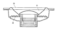
- the support structure of the diaphragm 31 is configured by a damper 32 and an edge portion 33 as shown in FIG. Further, as shown in FIG. 10, the electrodynamic speaker found in Patent Document 2 or the like is thinned by using only the edge portion 33 as a support system for the diaphragm 31.
- the speaker according to the present disclosure includes a diaphragm having an opening at the center, a voice coil, an edge portion, a frame, and a magnetic circuit.
- the voice coil is attached to the inner periphery of the diaphragm.
- the edge portion is attached to the outer periphery of the diaphragm.
- the frame supports the diaphragm via the edge portion.
- the magnetic circuit has a magnetic gap and is arranged on the frame so that the voice coil is positioned in the magnetic gap.
- the edge part is composed of a front side edge part and a back side edge part.
- the inner peripheral part of the front side edge part is fixed to the upper surface of the diaphragm, and the outer peripheral part of the front side edge part is fixed to the frame.
- the inner peripheral part of the back side edge part is fixed to the lower surface of the diaphragm, and the outer peripheral part of the back side edge part is fixed to the frame.
- the mechanical properties of the back edge portion are the same as the
- the diaphragm has a core material having a honeycomb structure in which a large number of holes are integrally formed, and a skin layer is bonded to each of an upper surface and a lower surface of the core material.
- frame is comprised by the front side edge part and the back side edge part, and the inner peripheral part of the front side edge part is fixed to the upper surface of a diaphragm,
- the outer peripheral part Is fixed to the frame.
- the inner peripheral portion of the back side edge portion is fixed to the lower surface of the diaphragm, and the outer peripheral portion thereof is fixed to the frame.
- the diaphragm when the integrally formed honeycomb structure core material is used for the diaphragm, the diaphragm can be made more uniform and more rigid than before, so that a wide-band speaker can be realized.
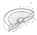
- FIG. 1 is a perspective view including a cross-sectional view taken along the center of a speaker according to an embodiment of the present disclosure.
- FIG. 2 is a perspective view including an enlarged cross-sectional view of a connection portion between the front edge portion, the back edge portion, the diaphragm, and the main frame.
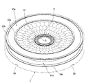
- FIG. 3 is a front view of the speaker.
- FIG. 4 is a side view of the speaker.
- FIG. 5 is a rear view of the speaker.
- FIG. 6 is a perspective view of a state in which the yoke is attached to the back frame.
- FIG. 7 is a perspective view of the core material of the diaphragm and the voice coil coupler bonded to the inner periphery thereof.
- FIG. 8 is a perspective view of a state in which the diaphragm to which the voice coil coupler is attached is attached to the main frame via the front side edge portion and the back side edge portion.
- FIG. 9 is a cross-sectional view of a conventional speaker (Patent Document 1).
- FIG. 10 is a cross-sectional view of a conventional speaker (Patent Document 2).
- the electrodynamic speaker found in Patent Document 1 is not suitable as a speaker embedded in an automobile door or an automobile ceiling because of its thick outer dimensions. Furthermore, since the diaphragm 31 has two different suspension structures of the damper 32 and the edge portion 33, there is a problem in that inherent nonlinear distortion occurs in each of them, and rolling in which the diaphragm 31 rolls easily occurs.
- the support system of the diaphragm 31 is thinned only by the edge portion 33, but the inner end of the edge portion 33 is bonded to the upper surface of the diaphragm 31. Therefore, strictly speaking, the support system of the diaphragm 31 is asymmetric. Therefore, some rolling of the diaphragm 31 remains. Further, the diaphragm 31 has a structure in which the first skin layer 35a is attached to the surface of the core material 34 and the second skin layer 35b is attached to the back surface. As the core material 34, there is a material using a foamed plate material. In addition, a strip-shaped thin plate is formed and bonded to the honeycomb structure to form the core material 34.
- Paper, resin, or metal is used for the strip-shaped thin plate.
- the rigidity of the diaphragm 31 can be increased when the thin plate is bonded to the honeycomb structure shape as compared with the core material 34 using a foam material.
- the bonding step increases, and the rigidity of the diaphragm 31 tends to be uneven.
- This disclosure provides a speaker that is thin and can be embedded in a door of a mobile device such as an automobile or a ceiling of an automobile, and is less likely to cause rolling.
- FIG. 1 and 2 are cross-sectional views showing the inside of the speaker of this embodiment.
- FIG. 4 and FIG. 5 show the front, side and back of the speaker of this embodiment, respectively.
- a frame is configured by combining the annular main frame 1 and the back frame 2.
- a vibration system structure is attached to the main frame 1.
- the main frame 1 supports a diaphragm 4 having a voice coil 3 attached to the inner periphery.
- FIG. 6 is a perspective view of the rear frame 2 with the yoke 6 attached thereto.
- a yoke 6 having an annular wall 5 formed on the outer periphery of the bottom is disposed at the center of the back frame 2.
- Slits 7 are formed at a plurality of locations in the circumferential direction of the annular wall 5.
- a disc-shaped magnet 8 and a magnetic plate 9 are arranged inside the annular wall 5 and in the center of the yoke 6. Between the inside of the tip of the annular wall 5 of the yoke 6 and the outer periphery of the plate 9, As shown in FIG. 2, a magnetic gap 10 is formed.
- the voice coil 3 disposed in the magnetic gap 10 is supported by the main frame 1 as shown below.
- FIG. 7 is a perspective view of the core material of the diaphragm and the voice coil coupler bonded to the inner periphery thereof. As shown in FIGS. 7 and 3, the voice coil 3 is bonded and fixed to the inner periphery of the voice coil coupler 11.
- the voice coil coupler 11 is a non-magnetic material and is integrally formed into a shape in which an inner ring 12 and an outer ring 13 are connected by a plurality of connecting portions 14. A hole 15 is formed between the plurality of connecting portions 14.
- the position of the connecting portion 14 of the voice coil coupler 11 corresponds to the position of the slit 7 of the yoke 6 shown in FIG. 1, and the width 16 of the connecting portion 14 of the voice coil coupler 11 is the slit of the yoke 6 shown in FIG. 1 and FIG. 2 in the assembled state, the magnetic circuit having a structure in which the tip of the annular wall 5 of the yoke 6 penetrates the inside of the hole 15 of the voice coil coupler 11 (slit structure magnetism). Circuit).
- the diaphragm 4 (see FIG. 1) has a core material 19 having a honeycomb structure in which a large number of polygonal holes 18 are formed. As shown in FIG. 2, the first skin layer 20a and the second skin layer 20b are attached to each other.
- the core material 19 was manufactured by a metal injection molding method (MIM metal powder injection molding method) in which a metal powder such as an aluminum alloy or a titanium alloy was mixed with a binder and injected into a mold.
- the core material 19 of the present embodiment is formed such that the inner peripheral side is thinner than the outer peripheral side.
- the size of the hole 18 of the core material 19 is such that the center of the diaphragm 4 is smaller than the outer periphery, and the density per unit area of the core material 19 is higher at the center of the diaphragm 4 than the outer periphery. It is molded into.
- the thickness of the inner peripheral side of the diaphragm 4 which is important for the reproduction of the sound of the middle and high frequency in the frequency characteristics is formed to be thinner than the thickness of the outer peripheral side.
- the inner peripheral side can be reduced in weight, and the sound pressure in the mid-high range can be improved.
- the rigidity of the inner periphery side of the diaphragm 4 is increased, and the sound pressure in the high range is increased. Can be improved.
- the outer peripheral side thickness of the diaphragm 4 is formed larger than the inner peripheral side thickness, the inter-fulcrum dimension between the front side edge portion 21a and the back side edge portion 21b (see FIG. 1) is increased, and vibration is generated. Occurrence of the rolling phenomenon of the plate can be suppressed, and vibration can be stabilized. Thus, gap defects can be reduced and distortion can be reduced.
- FIG. 8 is a perspective view of a state in which the diaphragm to which the voice coil coupler is attached is attached to the main frame via the front side edge portion and the back side edge portion.
- FIG. 8 shows the assembled state of the main frame 1 and the vibration system structure.
- the main frame 1 is illustrated by a virtual line.
- FIG. 2 shows an enlarged view of the connection between the front edge portion 21a and the back edge portion 21b and the diaphragm 4 and the main frame 1.
- the inner end portion 22 a of the front edge portion 21 a is bonded and fixed on the first skin layer 20 a that is affixed to the core material 19.
- the outer end portion 22 b of the front edge portion 21 a is bonded and fixed to the upper surface of the first step portion 23 a of the main frame 1.
- the inner terminal portion 24 a of the back side edge portion 21 b is bonded and fixed under the second skin layer 20 b attached to the core material 19.
- the outer end portion 24 b of the back side edge portion 21 b is bonded and fixed to the lower surface of the second step portion 23 b of the main frame 1.
- the front-side edge portion 21a is configured as an up-roll shape
- the back-side edge portion 21b is configured as a down-roll shape.
- the front side edge portion 21a and the back side edge portion 21b are symmetrical to each other, and in addition, since the mechanical characteristics are the same, the linearity with respect to the vertical amplitude of the diaphragm 4 can be improved, Low distortion can be realized.
- the meaning that the mechanical characteristics are the same here means that the displacement characteristics with respect to the force are the same.
- the material of the front side edge portion 21a and the back side edge portion 21b As for the material of the front side edge portion 21a and the back side edge portion 21b, a soft and lightweight material such as cloth, rubber, foam rubber, or elastomer is desirable. And about the material of the front side edge part 21a and the back side edge part 21b, the linearity of a speaker can be improved by combining the same material and making a mechanical characteristic the same.
- the material of the first skin layer 20a and the second skin layer 20b is preferably a light material such as aluminum or craft and having a certain degree of strength. By using these materials, the sound pressure level can be improved and the distortion can be reduced.
- the main frame 1 to which the diaphragm 4 and the voice coil 3 which is a part of the vibration system structure are attached via the front edge part 21a and the back edge part 21b, and a part of the vibration system structure
- the rear frame 2 to which the yoke 6, the magnet 8 and the plate 9 are attached is engaged with the recess 26 shown in FIG. 5 formed on the rear end surface of the main frame 1 at the front end of the support arm 25 of the rear frame 2.
- connection accuracy between the main frame 1 and the back frame 2 can be improved. Therefore, the assembly accuracy of the speaker can be improved, and gap defects can be reduced. Further, low distortion can be realized.
- the productivity can be improved, the price of the speaker can be reduced.
- the speaker assembled in this way is a slit-structure magnetic circuit in which the tip of the yoke 6 penetrates the inside of the hole 15 of the voice coil coupler 11, and a gap 27 is provided between the yoke 6 and the voice coil coupler 11 as shown in FIG. Therefore, the voice coil coupler 11 having the vibration system structure does not contact the yoke 6.
- the voice coil 3 is located in the magnetic gap 10 of the vibration system structure and does not contact the yoke 6 and the plate 9.
- the configuration using the slit structure magnetic circuit and the voice coil coupler 11 can also ensure the symmetry of the relationship between the magnetic circuit and the voice coil 3. Linearity can be improved and low distortion can be realized.
- the voice coil 3 includes a lead 29a and a wire 30a (see FIG. 3), a lead 29b and a wire from the terminal plates 28a and 28b fixed to the support arm 25 of the back frame 2, respectively. Power is supplied through 30b (see FIG. 3).
- the speaker 100 shown in FIG. 1 is a slit structure magnetic circuit, even if it is a thin speaker, the voice coil coupler 11 does not collide with the yoke 6 at the bottom dead center of the vibration system structure, and a large amplitude can be realized. .
- the front edge portion 21a and the back edge portion 21b are formed between the diaphragm 4 and the main frame 1 shown in FIG. 1, for example, the upper and lower front edge portions 21a and the back edge portion 21b are formed. Since the support system of the diaphragm 4 can be made completely symmetrical by aligning the mechanical characteristics of the front side edge portion 21a and the back side edge portion 21b, for example, by aligning the shape and material of the speaker with the same shape, the vibration system structure of the speaker Rolling is less likely to occur than conventional ones, and low distortion of the reproduced sound can be realized.
- the diaphragm 4 is a metal powder integrally formed part formed by a metal injection molding method (MIM) and has a honeycomb structure, a core material having a honeycomb-shaped hole formed by bonding thin plates with an adhesive Compared with the conventional diaphragms that make, the bonding process is not required, so the rigidity can be made uniform and the rigidity can be increased, so that low distortion and high performance can be realized.
- MIM metal injection molding method
- the loudspeaker 100 in which the diaphragm 4 has high rigidity, can realize a wider-band full-range speaker.
- the density of the honeycomb structure is configured to be higher at the center of the speaker 100, even the thin speaker 100 can emit a high sound faithfully from the center portion.
- the core material 19 may be formed using a foamed resin material. Since the skin layer is bonded to the upper surface and the lower surface of the core material 19 made of foamed resin, the weight can be reduced in the same manner as the honeycomb structure described above, so that the performance of the speaker can be improved. Can do.
- the foamed resin material of the core material 19 is composed of a closed cell foam.
- the foamed resin material of the core material 19 is made of polymethacrylimide.
- the resin material of the closed foam composed of polymethacrylimide As a specific example of the resin material of the closed foam composed of polymethacrylimide, Lohacel (Evonik, registered trademark) or the like can be used. As a result, high performance of the speaker can be realized.
- the speaker 100 according to the present embodiment is suitable for a full-range type speaker embedded in a car door or a car ceiling.
- This disclosure contributes to high performance of various thin speakers such as automobile speakers.
Landscapes
- Engineering & Computer Science (AREA)
- Physics & Mathematics (AREA)
- Acoustics & Sound (AREA)
- Signal Processing (AREA)
- Multimedia (AREA)
- Audible-Bandwidth Dynamoelectric Transducers Other Than Pickups (AREA)
- Diaphragms For Electromechanical Transducers (AREA)
Abstract
L'invention concerne un haut-parleur pourvu d'une membrane présentant une ouverture en son centre, une bobine acoustique, une partie de bord, un cadre et un circuit magnétique. La bobine acoustique est fixée à la périphérie interne de la membrane. La partie de bord est fixée à la périphérie externe de la membrane. Le cadre soutient la membrane sur la partie de bord. Le circuit magnétique présente un espace magnétique, et est disposé sur le cadre de sorte que la bobine acoustique est placée dans l'espace magnétique. La partie de bord est conçue à partir d'une partie de bord latéral avant et d'une partie de bord latéral arrière. La section périphérique interne de la partie de bord latéral avant est fixée à la surface supérieure de la membrane, et la section périphérique externe de la partie de bord latéral avant est fixée au cadre. La section périphérique interne de la partie de bord latéral arrière est solidement fixée à la surface inférieure de la membrane, et la section périphérique externe de la partie de bord latéral arrière est solidement fixée au cadre. Les caractéristiques mécaniques de la partie de bord latéral arrière sont identiques aux caractéristiques mécaniques de la partie de bord latéral avant.
Priority Applications (1)
| Application Number | Priority Date | Filing Date | Title |
|---|---|---|---|
| JP2018502575A JPWO2017149984A1 (ja) | 2016-02-29 | 2017-01-20 | スピーカ |
Applications Claiming Priority (2)
| Application Number | Priority Date | Filing Date | Title |
|---|---|---|---|
| JP2016036522 | 2016-02-29 | ||
| JP2016-036522 | 2016-02-29 |
Publications (1)
| Publication Number | Publication Date |
|---|---|
| WO2017149984A1 true WO2017149984A1 (fr) | 2017-09-08 |
Family
ID=59743766
Family Applications (1)
| Application Number | Title | Priority Date | Filing Date |
|---|---|---|---|
| PCT/JP2017/001878 Ceased WO2017149984A1 (fr) | 2016-02-29 | 2017-01-20 | Haut-parleur |
Country Status (2)
| Country | Link |
|---|---|
| JP (1) | JPWO2017149984A1 (fr) |
| WO (1) | WO2017149984A1 (fr) |
Cited By (2)
| Publication number | Priority date | Publication date | Assignee | Title |
|---|---|---|---|---|
| GB2573888A (en) * | 2018-05-04 | 2019-11-20 | Tymphany Acoustic Tech Huizhou Co Ltd | Loudspeaker |
| EP3697105A4 (fr) * | 2017-10-13 | 2020-12-09 | Foster Electric Co. Ltd. | Unité de haut-parleur |
Citations (9)
| Publication number | Priority date | Publication date | Assignee | Title |
|---|---|---|---|---|
| JPS5668385U (fr) * | 1979-11-01 | 1981-06-06 | ||
| JPS5687796U (fr) * | 1979-12-07 | 1981-07-14 | ||
| JPS58153493A (ja) * | 1982-02-22 | 1983-09-12 | エヌ・ベ−・フイリツプス・フル−イランペンフアブリケン | 電気−音響変換器 |
| JPS6052797U (ja) * | 1983-09-20 | 1985-04-13 | ソニー株式会社 | エツジレススピ−カ |
| JPS60181991U (ja) * | 1984-05-15 | 1985-12-03 | シャープ株式会社 | スピ−カ用振動板 |
| JPS61396U (ja) * | 1984-06-04 | 1986-01-06 | オンキヨー株式会社 | 平板型スピ−カ− |
| JP2002036217A (ja) * | 2000-07-28 | 2002-02-05 | Ngk Insulators Ltd | ハニカム成形体及びその製造方法 |
| WO2007058133A1 (fr) * | 2005-11-15 | 2007-05-24 | Pioneer Corporation | Haut-parleur et circuit magnétique |
| WO2014162411A1 (fr) * | 2013-04-01 | 2014-10-09 | パイオニア株式会社 | Membrane pour dispositif de haut-parleur |
Family Cites Families (1)
| Publication number | Priority date | Publication date | Assignee | Title |
|---|---|---|---|---|
| DE60308659T2 (de) * | 2003-06-04 | 2007-08-23 | Harman Becker Automotive Systems Gmbh | Lautsprecher |
-
2017
- 2017-01-20 WO PCT/JP2017/001878 patent/WO2017149984A1/fr not_active Ceased
- 2017-01-20 JP JP2018502575A patent/JPWO2017149984A1/ja active Pending
Patent Citations (9)
| Publication number | Priority date | Publication date | Assignee | Title |
|---|---|---|---|---|
| JPS5668385U (fr) * | 1979-11-01 | 1981-06-06 | ||
| JPS5687796U (fr) * | 1979-12-07 | 1981-07-14 | ||
| JPS58153493A (ja) * | 1982-02-22 | 1983-09-12 | エヌ・ベ−・フイリツプス・フル−イランペンフアブリケン | 電気−音響変換器 |
| JPS6052797U (ja) * | 1983-09-20 | 1985-04-13 | ソニー株式会社 | エツジレススピ−カ |
| JPS60181991U (ja) * | 1984-05-15 | 1985-12-03 | シャープ株式会社 | スピ−カ用振動板 |
| JPS61396U (ja) * | 1984-06-04 | 1986-01-06 | オンキヨー株式会社 | 平板型スピ−カ− |
| JP2002036217A (ja) * | 2000-07-28 | 2002-02-05 | Ngk Insulators Ltd | ハニカム成形体及びその製造方法 |
| WO2007058133A1 (fr) * | 2005-11-15 | 2007-05-24 | Pioneer Corporation | Haut-parleur et circuit magnétique |
| WO2014162411A1 (fr) * | 2013-04-01 | 2014-10-09 | パイオニア株式会社 | Membrane pour dispositif de haut-parleur |
Cited By (4)
| Publication number | Priority date | Publication date | Assignee | Title |
|---|---|---|---|---|
| EP3697105A4 (fr) * | 2017-10-13 | 2020-12-09 | Foster Electric Co. Ltd. | Unité de haut-parleur |
| US11284198B2 (en) | 2017-10-13 | 2022-03-22 | Foster Electric Company, Limited | Speaker unit |
| GB2573888A (en) * | 2018-05-04 | 2019-11-20 | Tymphany Acoustic Tech Huizhou Co Ltd | Loudspeaker |
| GB2573888B (en) * | 2018-05-04 | 2021-02-17 | Tymphany Acoustic Tech Huizhou Co Ltd | Loudspeaker |
Also Published As
| Publication number | Publication date |
|---|---|
| JPWO2017149984A1 (ja) | 2018-12-20 |
Similar Documents
| Publication | Publication Date | Title |
|---|---|---|
| US9601682B2 (en) | Electroacoustic transducer | |
| CN107889553B (zh) | 扬声器及耳机 | |
| US9654881B2 (en) | Electroacoustic transducer | |
| KR101156053B1 (ko) | 마이크로 스피커 | |
| US10932050B2 (en) | Micro-speaker | |
| JP5700704B2 (ja) | スピーカ装置 | |
| US20160165351A1 (en) | Diaphragm And Speaker Using Same | |
| WO2006082774A1 (fr) | Haut-parleur | |
| KR101184537B1 (ko) | 스피커 | |
| JP4750212B1 (ja) | スピーカ | |
| KR101595175B1 (ko) | 이중 구동부를 갖는 마이크로 스피커 | |
| WO2007091515A1 (fr) | Haut-parleur | |
| WO2017149984A1 (fr) | Haut-parleur | |
| JP2011101074A (ja) | 動電型スピーカーおよびこれに用いる振動部材 | |
| JP2002218585A (ja) | スピーカ | |
| JP2013013021A (ja) | 電気音響変換器 | |
| CN110235452B (zh) | 扬声器振动板和扬声器装置 | |
| JP2012044352A (ja) | スピーカー | |
| JP2020120400A (ja) | 電気音響ドライバ | |
| WO2017104124A1 (fr) | Transducteur électro-acoustique | |
| JPH11275690A (ja) | スピーカ | |
| JP6436530B2 (ja) | 動電型電気音響変換器及びその製造方法 | |
| US11678122B2 (en) | Speaker | |
| WO2017104125A1 (fr) | Transducteur électro-acoustique | |
| JP3991919B2 (ja) | スピーカ用振動板 |
Legal Events
| Date | Code | Title | Description |
|---|---|---|---|
| WWE | Wipo information: entry into national phase |
Ref document number: 2018502575 Country of ref document: JP |
|
| NENP | Non-entry into the national phase |
Ref country code: DE |
|
| 121 | Ep: the epo has been informed by wipo that ep was designated in this application |
Ref document number: 17759456 Country of ref document: EP Kind code of ref document: A1 |
|
| 122 | Ep: pct application non-entry in european phase |
Ref document number: 17759456 Country of ref document: EP Kind code of ref document: A1 |