WO2017149996A1 - Appareil de station terminale, et procédé d'attribution de bande - Google Patents
Appareil de station terminale, et procédé d'attribution de bande Download PDFInfo
- Publication number
- WO2017149996A1 WO2017149996A1 PCT/JP2017/002136 JP2017002136W WO2017149996A1 WO 2017149996 A1 WO2017149996 A1 WO 2017149996A1 JP 2017002136 W JP2017002136 W JP 2017002136W WO 2017149996 A1 WO2017149996 A1 WO 2017149996A1
- Authority
- WO
- WIPO (PCT)
- Prior art keywords
- terminal device
- bandwidth allocation
- resource information
- interval
- terminal
- Prior art date
- Legal status (The legal status is an assumption and is not a legal conclusion. Google has not performed a legal analysis and makes no representation as to the accuracy of the status listed.)
- Ceased
Links
Images



Classifications
-
- H—ELECTRICITY
- H04—ELECTRIC COMMUNICATION TECHNIQUE
- H04W—WIRELESS COMMUNICATION NETWORKS
- H04W72/00—Local resource management
- H04W72/12—Wireless traffic scheduling
- H04W72/1221—Wireless traffic scheduling based on age of data to be sent
-
- H—ELECTRICITY
- H04—ELECTRIC COMMUNICATION TECHNIQUE
- H04J—MULTIPLEX COMMUNICATION
- H04J3/00—Time-division multiplex systems
- H04J3/16—Time-division multiplex systems in which the time allocation to individual channels within a transmission cycle is variable, e.g. to accommodate varying complexity of signals, to vary number of channels transmitted
-
- H—ELECTRICITY
- H04—ELECTRIC COMMUNICATION TECHNIQUE
- H04L—TRANSMISSION OF DIGITAL INFORMATION, e.g. TELEGRAPHIC COMMUNICATION
- H04L12/00—Data switching networks
- H04L12/28—Data switching networks characterised by path configuration, e.g. LAN [Local Area Networks] or WAN [Wide Area Networks]
- H04L12/44—Star or tree networks
-
- H—ELECTRICITY
- H04—ELECTRIC COMMUNICATION TECHNIQUE
- H04W—WIRELESS COMMUNICATION NETWORKS
- H04W56/00—Synchronisation arrangements
- H04W56/001—Synchronization between nodes
-
- H—ELECTRICITY
- H04—ELECTRIC COMMUNICATION TECHNIQUE
- H04W—WIRELESS COMMUNICATION NETWORKS
- H04W56/00—Synchronisation arrangements
- H04W56/003—Arrangements to increase tolerance to errors in transmission or reception timing
-
- H—ELECTRICITY
- H04—ELECTRIC COMMUNICATION TECHNIQUE
- H04W—WIRELESS COMMUNICATION NETWORKS
- H04W72/00—Local resource management
- H04W72/04—Wireless resource allocation
- H04W72/044—Wireless resource allocation based on the type of the allocated resource
- H04W72/0453—Resources in frequency domain, e.g. a carrier in FDMA
Definitions
- the present invention relates to a communication technique in a passive optical communication network system.
- This application claims priority based on Japanese Patent Application No. 2016-038416 filed in Japan on February 29, 2016, the contents of which are incorporated herein by reference.
- a typical example of optical access is FTTH (Fiber To The Home).
- FTTH Fiber To The Home
- a passive optical communication network in which a terminal device and a plurality of terminal devices are generally connected is used. With such a configuration, the optical access realizes economical service provision.
- communication between a terminal device and a terminal device is multiplexed by a time division multiplexing method. Communication from the terminal device to the terminal device (hereinafter referred to as “uplink communication”) is realized using a control protocol called MPCP (Multi-Point Control Protocol) (see Non-Patent Document 1).
- MPCP Multi-Point Control Protocol
- the transmission amount and transmission start time in uplink communication of each terminal device are centrally controlled in the terminal device.
- MPCP Multi-Point Control Protocol
- a communication system in which another communication network is accommodated via a passive optical communication network has also been proposed.
- control is performed in cooperation with a terminal device of a passive optical communication network and a host device connected to a higher level of the terminal station device.
- a technique for realizing an economical network construction by applying a passive optical communication network to a mobile radio communication service network (hereinafter referred to as a “mobile network”) having a severe delay requirement (see Patent Document 2).
- mobile networks include LTE (Long Term Evolution) and LTE-advanced.
- the terminal station device performs band allocation to each terminal device using the radio resource information notified from the host device. At this time, it is necessary to synchronize the clock between the terminal device and the host device.
- ⁇ Clock synchronization may be lost between the terminal device and the host device due to device abnormality.
- the terminal device and the host device each have the clock source, the operation can be continued independently based on the clocks output from the respective clock sources.
- the time between the terminal device and the host device is greatly shifted as time passes. That is, as the time elapses, the timing at which the terminal apparatus executes the bandwidth allocation deviates from the timing that should be originally executed. For this reason, there is a possibility that an ideal bandwidth allocation cannot be performed and a delay increases.
- an object of the present invention is to provide a technique capable of reducing a shift in timing at which a terminal device executes bandwidth allocation.
- the host device, the terminal device, the terminal device, and the lower device are communicably connected in this order, and the host device can be used for communication with the lower device.
- It is a terminal device of a communication system that allocates the resource to the lower-level device by notifying resource information indicating a valid resource.
- the terminal device includes a bandwidth allocating unit that allocates a bandwidth that the terminal device is allowed to use for transmission processing to the terminal device based on an interval at which the resource information is received by the terminal device. Prepare.
- the host device, the terminal device, the terminal device, and the lower device are communicably connected in this order, and the host device can be used for communication with the lower device.
- This is a bandwidth allocation method performed by the terminal device of the communication system that allocates the resource to the lower-level device by notifying resource information indicating a valid resource.
- the band allocation method includes allocating a band that is permitted to be used by the terminal device for transmission processing to the terminal device based on an interval at which the resource information is received by the terminal device.
- FIG. 1 shows the system configuration example of the communication system (communication system 100) of 1st embodiment. It is a schematic block diagram which shows the function structure of the terminal station apparatus 20 in 1st embodiment. It is a flowchart which shows the specific example of the flow of a process of the terminal device 20 in 1st embodiment. It is a schematic block diagram which shows the function structure of the terminal station apparatus 20a in 2nd embodiment. It is a flowchart which shows the specific example of the flow of a process of the terminal device 20a in 2nd embodiment.
- FIG. 1 is a diagram illustrating a system configuration example of a communication system (communication system 100) according to the first embodiment.
- the communication system 100 includes a host device 10, a terminal device 20, a plurality of termination devices 30, and a plurality of lower devices 40.
- the host device 10 is connected to a host network 60 corresponding to the host network of the communication system 100.
- the host device 10 and the terminal device 20 are connected one to one.
- the terminal station device 20 and the plurality of terminal devices 30 are connected to each other via a relay network 70 so that they can communicate with each other.
- Each subordinate device 40 may be communicably connected to a plurality of user devices 50 via a subordinate network 80.
- the host device 10 is communicably connected to the plurality of lower devices 40 via the terminal station device 20, the relay network 70, and the plurality of termination devices 30.
- the relay network 70 includes a relay unit 71.
- the relay unit 71 is a device that branches light.
- the relay unit 71 is, for example, an optical splitter.
- the relay unit 71 may be a multiplexing device that multiplexes or separates optical signals.
- the host device 10 is a device that realizes a predetermined function by communicating with a plurality of lower devices 40.
- the host device 10 is, for example, a base station device (BBU: Bas Band Unit) in a mobile network.
- BBU Bas Band Unit
- the terminal device 20 is a device that terminates the relay network 70 on the upper side.
- the terminal device 20 is, for example, an optical subscriber line terminal device (OLT: Optical Line Terminal).
- OLT optical Subscriber Line Terminal
- the terminal device 20 executes a bandwidth allocation process based on the radio resource information notified from the higher-level device 10. By executing the bandwidth allocation process, the terminal device 20 determines the transmission amount and transmission start time in uplink communication for the plurality of termination devices 30.
- the terminating device 30 is a device that terminates the relay network 70 on the lower side.
- the terminating device 30 is, for example, an optical line terminating device (ONU: Optical Network Unit).
- the termination device 30 is connected to the lower device 40 on a one-to-one basis.
- the lower device 40 is a device that realizes a predetermined function by communicating with the upper device 10.
- the lower device 40 is a device installed at a position closer to the user side than the upper device 10.
- the upper level device 10 is a BBU
- the lower level device 40 is a radio device (RRH: Remote Radio Head) in the mobile network.
- the lower device 40 accommodates a plurality of user devices 50, for example.
- the lower apparatus 40 starts transmission of uplink data based on the scheduling information notified from the upper apparatus 10. Such processing may be performed by the user device 50.
- the user device 50 is a device that is communicably connected to another device via the relay network 70 and the upper network 60 by connecting to the lower device 40 via the lower network 80.
- the user device 50 is an information processing device such as a smartphone, a tablet, or a computer.
- the user device 50 may be, for example, a sensor in IoT (Internet of Things).
- the user device 50 may be a device for business use such as an ATM (Automatic Teller Machine), a vending machine, or a POS (Point Of Sale) terminal.
- FIG. 2 is a schematic block diagram showing a functional configuration of the terminal device 20 in the first embodiment.
- the terminal device 20 includes a cooperative IF (interface) 201, a bandwidth allocation unit 202, an upper communication unit 203, and a lower communication unit 204.
- the cooperation IF 201 may be an example of an interface.
- the upper communication unit 203 may be an example of an interface.
- the functions of the cooperation IF 201, the bandwidth allocation unit 202, the higher-level communication unit 203, and the lower-level communication unit 204 may be realized by executing a program with a CPU (Central Processing Unit) and a memory included in the terminal device 20, for example.
- CPU Central Processing Unit
- All or some of the above functions may be realized by using hardware such as an application specific integrated circuit (ASIC), a programmable logic device (PLD), and a field programmable gate array (FPGA).
- ASIC application specific integrated circuit
- PLD programmable logic device
- FPGA field programmable gate array
- the program to be executed may be recorded on a computer-readable recording medium.
- the computer-readable recording medium is, for example, a portable medium such as a flexible disk, a magneto-optical disk, a ROM, a CD-ROM, or a storage device such as a hard disk built in the computer system.
- the program may be transmitted via a telecommunication line.
- the cooperation IF 201 includes a communication interface for performing communication with the host device 10.
- the cooperation IF 201 receives a synchronization signal and radio resource information from the higher-level device 10.
- the synchronization signal is a signal used by the terminal station device 20 to synchronize the frequency with the clock source of the host device 10.
- the synchronization signal is, for example, a SyncE (Synchronous Ethernet (registered trademark)), PTP (Precision Time Protocol), 1 PPS (Pulse Per Second), 10 MHz signal.
- the terminal device 20 synchronizes its own clock with the clock of the host device 10 based on the synchronization signal.
- the radio resource information is information related to radio channel allocation between the lower level device 40 and the user device 50.
- the radio resource information includes, for example, allocation destination information, resource information, and communication destination information.
- the allocation destination information is information indicating the user device 50 to which the radio resource is allocated.
- the resource information is information indicating the assigned radio resource.
- the communication destination information is information indicating the lower device 40 that is a communication partner of the user device 50. For example, the radio resource information is notified to the terminal device 20 at a cycle in which the higher-level device 10 generates scheduling information.
- the bandwidth allocation unit 202 executes bandwidth allocation processing based on the radio resource information received by the cooperation IF 201. Specifically, it is as follows. Based on the radio resource information, the bandwidth allocation unit 202 acquires in advance information indicating the amount of uplink data arriving at each terminal device 30 and the arrival time. The bandwidth allocation unit 202 creates and notifies the transmission permission to each terminal device 30 in accordance with the arrival time of the uplink data. Notification of transmission permission is performed via the lower communication unit 204.
- the transmission permission is information related to transmission that each terminal device 30 is permitted to perform to the terminal device 20.
- the transmission permission includes, for example, the transmission start time and the transmission permission amount in each terminal device 30.
- the transmission start time indicates a time when the terminal device 30 is permitted to start transmission processing with respect to the terminal device 20.
- the transmission permission amount indicates the amount of data that is permitted for the terminal device 30 to perform transmission processing on the terminal device 20.
- the host communication unit 203 includes a communication interface for performing communication with the host device 10.
- the upper communication unit 203 is, for example, SNI (ServiceINode Interface).
- the upper communication unit 203 transmits / receives a main signal to / from the upper device 10.
- the upper communication unit 203 receives the main signal transmitted from the upper device 10 and relays the received main signal to the lower communication unit 204.
- the upper communication unit 203 relays the main signal received by the lower communication unit 204 to the upper device 10.
- wireless resource information is contained in the main signal
- the lower communication unit 204 includes a communication interface for performing communication with the terminal device 30 via the relay network 70.
- the lower communication unit 204 is, for example, a PON (passive optical network) -IF.
- the lower communication unit 204 transmits and receives a main signal to and from the termination device 30.
- the lower communication unit 204 receives the main signal transmitted from the termination device 30 and relays the received main signal to the upper communication unit 203.
- the lower communication unit 204 relays the main signal received by the upper communication unit 203 to the termination device 30.
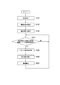
- FIG. 3 is a flowchart showing a specific example of the processing flow of the terminal device 20 in the first embodiment.
- the bandwidth allocation unit 202 executes an initial setting process (step S101).
- the bandwidth allocation unit 202 sets each value of a radio resource information notification interval, a DBA (dynamic bandwidth allocation) cycle, a DBA end time, and a clock magnification.
- the radio resource information notification interval is a time interval at which the host device 10 notifies the terminal device 20 of radio resource information.
- the DBA cycle is a time to be allocated when the bandwidth allocation unit 202 executes the bandwidth allocation process.
- the DBA end time is the end time of the allocation target time when the bandwidth allocation unit 202 executes the bandwidth allocation process last time.
- the initial value of the DBA end time is “0”.
- the clock magnification is a coefficient indicating a clock synchronization shift between the higher-level device 10 and the terminal device 20.
- the initial value of the clock magnification is “1”.
- Band allocating section 202 calculates the period ratio based on Equation 1. That is, the bandwidth allocation unit 202 calculates the ratio between the DBA cycle and the radio resource information notification interval as the cycle ratio (step S102).
- the bandwidth allocation unit 202 waits until both of the following two conditions are satisfied (steps S103 and S104—NO).
- Condition 1 The previous bandwidth allocation target time has expired. That is, the current time exceeds the DBA end time.
- Condition 2 New radio resource information is received.
- step S104—YES the bandwidth allocation unit 202 calculates a new clock magnification (step S105). The new clock magnification is calculated based on Equation 2 below.
- the previous clock magnification indicates the clock magnification calculated in the previous cycle.
- the radio resource information reception interval indicates the time from when the previous radio resource information is received until the current radio resource information is received.
- the DBA cycle value used in Equation 2 is the DBA cycle value calculated in the previous cycle.
- the bandwidth allocation unit 202 sets a new DBA cycle (step S306).
- the bandwidth allocation unit 202 calculates a new DBA cycle based on the following Equation 3.
- the bandwidth allocation unit 202 executes bandwidth allocation processing for each terminal device 30 (step S107).
- the bandwidth allocation unit 202 acquires a request amount based on the radio resource information.
- the bandwidth allocating unit 202 determines a bandwidth to be allocated to each terminal device 30 using the newly set DBA cycle as an allocation target time. More specifically, the bandwidth allocation unit 202 allocates a value obtained by multiplying the acquired request amount by the clock magnification as a bandwidth for the termination device 30.
- the bandwidth allocation unit 202 can allocate a bandwidth to the termination device 30 so as not to exceed the bandwidth that can be allocated in one DBA cycle.
- the bandwidth allocation unit 202 updates the DBA end time to the sum (time) obtained by adding the DBA period to the current time.
- the bandwidth allocation unit 202 repeatedly executes the processing of the flowchart shown in FIG.
- the bandwidth allocation unit 202 of the terminal device 20 calculates the DBA cycle based on the radio resource information reception interval. Then, the DBA cycle is determined so that the band allocation start time coincides with the reception time of the radio resource information. For example, when the clock in the terminal device 20 is late, the start time of band allocation is delayed. In response to such a problem, the bandwidth allocating unit 202 shortens the DBA cycle, and thus can suppress the expansion of the influence of the clock shift. On the other hand, when the clock at the terminal device 20 is early, the start time of band allocation is advanced, and radio resource information does not reach before the start of band allocation.
- the bandwidth allocating unit 202 lengthens the DBA cycle, so that it is possible to suppress the expansion of the influence of the clock shift.
- the clock synchronization is deviated between the higher-level device 10 and the terminal device 20, it is possible to prevent the timing difference at which the terminal device 20 performs the band allocation process from becoming large. be able to.
- uplink communication (communication in the direction from the lower apparatus 40 to the upper apparatus 10) can be maintained.
- the transmission of the synchronization signal and the radio resource information from the higher-level device 10 to the terminal station device 20 is performed through a communication path different from that of the main signal.
- either or both of the synchronization signal and the radio resource information may be transmitted through the same communication path as that of the main signal.
- FIG. 4 is a schematic block diagram showing a functional configuration of the terminal device 20a in the second embodiment.
- the terminal device 20a further includes a synchronization state detection unit 211 in addition to the cooperation IF 201, the bandwidth allocation unit 202, the upper communication unit 203, and the lower communication unit 204.
- the function of the synchronization state detection unit 211 may be realized, for example, by executing a program by a CPU and a memory included in the terminal device 20a.
- all or part of the functions of the synchronization state detection unit 211 may be realized using hardware such as an ASIC, PLD, or FPGA.
- the program to be executed may be recorded on a computer-readable recording medium.
- the computer-readable recording medium is, for example, a portable medium such as a flexible disk, a magneto-optical disk, a ROM, a CD-ROM, or a storage device such as a hard disk built in the computer system.
- the program may be transmitted via a telecommunication line.
- the difference between the terminal device 20a of the second embodiment and the terminal device 20 of the first embodiment will be described.
- the synchronization state detection unit 211 determines whether or not the clock is synchronized between the host device 10 and the own device (terminal device 20a) based on the synchronization signal transmitted from the host device 10. For example, the synchronization state detection unit 211 may determine that the synchronization signal is not synchronized when the synchronization signal cannot be received from the higher-level device 10. For example, when the clock shift exceeds a predetermined threshold, the synchronization state detection unit 211 may determine that the synchronization is not synchronized.
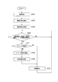
- FIG. 5 is a flowchart showing a specific example of the processing flow of the terminal device 20a in the second embodiment.
- description is abbreviate
- step S104-YES determines whether or not the clock is synchronized between the host device 10 and the own device (terminal device 20a).
- Step S111 determines whether or not the clock is synchronized between the host device 10 and the own device (terminal device 20a).
- step S111—NO the bandwidth allocation unit 202 calculates the clock magnification and the DBA cycle (steps S105 and S106). By this processing, the clock magnification and DBA cycle values are updated according to the radio resource information reception interval. Then, the bandwidth allocation unit 202 performs bandwidth allocation processing (step S107).
- the bandwidth allocation unit 202 performs the bandwidth allocation processing without calculating the clock magnification and the DBA cycle (step S107). In this case, the processing of the bandwidth allocation unit 202 is executed based on a clock (clock of the terminal device 20) synchronized with the higher-level device 10.
- the clock magnification and the DBA cycle are calculated only when it is determined that the clocks are not synchronized. Therefore, it is possible to reduce the amount of calculation executed by the bandwidth allocation unit 202 and reduce the processing resource burden in the bandwidth allocation unit 202. Moreover, in the terminal station apparatus 20a of 2nd embodiment, it becomes possible to acquire the effect similar to the terminal station apparatus 20 of 1st embodiment.
- the host device, the terminal device, the terminal device, and the lower device are connected to be communicable in this order, and the host device uses resources that can be used for communication with the lower device.
- It is a terminal device of a communication system that allocates the resource to the lower-level device by notifying resource information to be indicated.
- the terminal device includes a bandwidth allocating unit that allocates a bandwidth that the terminal device is allowed to use for transmission processing to the terminal device based on an interval at which the resource information is received by the terminal device. Prepare.
- the terminal device may further include an interface that receives the resource information from the host device.
- the band allocation unit may allocate the band based on an interval at which the resource information is received by the interface.
- the bandwidth allocating unit determines a dynamic bandwidth allocation period, which is a target time of bandwidth allocation that the termination device is allowed to use for transmission processing to the terminal device. May be.
- the bandwidth allocating unit may determine the dynamic bandwidth based on a ratio of an interval at which the resource information is received to an interval at which the host device notifies the resource information to the terminal device. An allocation cycle may be determined.
- the bandwidth allocating unit includes a previous dynamic bandwidth allocation period, an interval at which the resource information is received, and an interval at which the host device notifies the terminal device of the resource information. Based on the above, a new dynamic band allocation cycle may be determined.
- the bandwidth allocating unit may generate a new dynamic bandwidth if the interval at which the resource information is received is longer than the interval at which the host device notifies the resource information to the terminal device.
- the allocation period may be determined to be longer than the previous dynamic band allocation period. If the interval at which the resource information is received is shorter than the interval at which the higher-level device notifies the terminal device of the resource information, the bandwidth allocation unit sets a new dynamic bandwidth allocation period to the previous dynamic bandwidth allocation period. You may determine to a period shorter than a band allocation period.
- the terminal device may further include a synchronization state detection unit that determines whether the clock of the terminal device is synchronized with the clock of the host device.
- the band allocating unit may perform band allocation based on the clock of the terminal station device when the synchronization state detecting unit determines that the clock of the terminal station device is synchronized.
- the bandwidth allocation unit may perform bandwidth allocation based on an interval at which the resource information is received when the synchronization state detection unit determines that the clocks of the terminal devices are not synchronized. .
- the present invention may be applied to a terminal device and a bandwidth allocation method.
Landscapes
- Engineering & Computer Science (AREA)
- Computer Networks & Wireless Communication (AREA)
- Signal Processing (AREA)
- Mobile Radio Communication Systems (AREA)
- Small-Scale Networks (AREA)
Abstract
L'invention concerne un appareil de station terminale utilisable dans un système de communication dans lequel un dispositif d'ordre élevé, un appareil de station terminale, un appareil de terminal d'extrémité, et un dispositif d'ordre inférieur, sont connectés dans cet ordre pour une communication. Le dispositif d'ordre élevé indique au dispositif d'ordre inférieur des informations de ressources concernant des ressources utilisables pour une communication, de sorte que les ressources peuvent être attribuées au dispositif d'ordre inférieur. L'appareil de station terminale comprend une unité d'attribution de bande qui, sur la base de l'intervalle auquel les informations de ressources sont reçues par l'appareil de station terminale, attribue une bande pouvant être utilisée par l'appareil de terminal d'extrémité pour exécuter un processus d'envoi d'une transmission à l'appareil de station terminale.
Priority Applications (2)
| Application Number | Priority Date | Filing Date | Title |
|---|---|---|---|
| US16/075,205 US10555330B2 (en) | 2016-02-29 | 2017-01-23 | Terminal station apparatus and band allocation method |
| JP2018502583A JP6568642B2 (ja) | 2016-02-29 | 2017-01-23 | 端局装置及び帯域割当方法 |
Applications Claiming Priority (2)
| Application Number | Priority Date | Filing Date | Title |
|---|---|---|---|
| JP2016-038416 | 2016-02-29 | ||
| JP2016038416 | 2016-02-29 |
Publications (1)
| Publication Number | Publication Date |
|---|---|
| WO2017149996A1 true WO2017149996A1 (fr) | 2017-09-08 |
Family
ID=59743778
Family Applications (1)
| Application Number | Title | Priority Date | Filing Date |
|---|---|---|---|
| PCT/JP2017/002136 Ceased WO2017149996A1 (fr) | 2016-02-29 | 2017-01-23 | Appareil de station terminale, et procédé d'attribution de bande |
Country Status (3)
| Country | Link |
|---|---|
| US (1) | US10555330B2 (fr) |
| JP (1) | JP6568642B2 (fr) |
| WO (1) | WO2017149996A1 (fr) |
Cited By (2)
| Publication number | Priority date | Publication date | Assignee | Title |
|---|---|---|---|---|
| JPWO2017221874A1 (ja) * | 2016-06-20 | 2018-11-08 | 日本電信電話株式会社 | 光伝送装置及び帯域割当方法 |
| JP2019062315A (ja) * | 2017-09-25 | 2019-04-18 | 沖電気工業株式会社 | 局側装置、光アクセスネットワーク、及び、帯域割当方法 |
Citations (3)
| Publication number | Priority date | Publication date | Assignee | Title |
|---|---|---|---|---|
| US20070041384A1 (en) * | 2005-07-20 | 2007-02-22 | Immenstar Inc. | Intelligent bandwidth allocation for ethernet passive optical networks |
| JP2009152916A (ja) * | 2007-12-21 | 2009-07-09 | Hitachi Communication Technologies Ltd | ネットワークシステム及びolt |
| WO2014061552A1 (fr) * | 2012-10-19 | 2014-04-24 | 日本電信電話株式会社 | Système de station de base de communication radio distribuée, unité de bande de base, unité de radio distante et procédé de fonctionnement d'un système de station de base de communication radio distribuée |
Family Cites Families (9)
| Publication number | Priority date | Publication date | Assignee | Title |
|---|---|---|---|---|
| JP3768421B2 (ja) | 2001-09-10 | 2006-04-19 | 日本電信電話株式会社 | 動的帯域割当回路、動的帯域割当方法、動的帯域割当プログラムおよび記録媒体 |
| EP2290839A1 (fr) * | 2008-06-20 | 2011-03-02 | Mitsubishi Electric Corporation | Dispositif de communication et système de communication sans fil |
| JP5259840B2 (ja) * | 2009-12-01 | 2013-08-07 | 富士通株式会社 | 周波数偏差推定方法及び基地局装置 |
| JP5876941B2 (ja) | 2012-11-14 | 2016-03-02 | 日本電信電話株式会社 | 光加入者通信システム、光加入者通信方法、上位装置及び光加入者線終端装置 |
| CN106576248B (zh) * | 2014-08-21 | 2020-03-06 | 日本电信电话株式会社 | 无线通信系统、无线通信方法、协作控制装置、终端装置、以及许可频带基站装置 |
| US9813863B2 (en) * | 2015-08-06 | 2017-11-07 | Qualcomm Incorporated | Enhanced passive positioning with adaptive active positioning |
| CN107041012B (zh) * | 2016-02-03 | 2022-11-22 | 北京三星通信技术研究有限公司 | 基于差分波束的随机接入方法、基站设备及用户设备 |
| CN108781375B (zh) * | 2016-04-01 | 2020-10-09 | 华为技术有限公司 | 上行数据传输的方法和设备 |
| JP2020010075A (ja) * | 2016-11-11 | 2020-01-16 | シャープ株式会社 | 端末装置、基地局装置、通信方法、および、集積回路 |
-
2017
- 2017-01-23 WO PCT/JP2017/002136 patent/WO2017149996A1/fr not_active Ceased
- 2017-01-23 JP JP2018502583A patent/JP6568642B2/ja active Active
- 2017-01-23 US US16/075,205 patent/US10555330B2/en active Active
Patent Citations (3)
| Publication number | Priority date | Publication date | Assignee | Title |
|---|---|---|---|---|
| US20070041384A1 (en) * | 2005-07-20 | 2007-02-22 | Immenstar Inc. | Intelligent bandwidth allocation for ethernet passive optical networks |
| JP2009152916A (ja) * | 2007-12-21 | 2009-07-09 | Hitachi Communication Technologies Ltd | ネットワークシステム及びolt |
| WO2014061552A1 (fr) * | 2012-10-19 | 2014-04-24 | 日本電信電話株式会社 | Système de station de base de communication radio distribuée, unité de bande de base, unité de radio distante et procédé de fonctionnement d'un système de station de base de communication radio distribuée |
Non-Patent Citations (1)
| Title |
|---|
| TASHIRO, T ET AL.: "A novel DBA scheme for TDM-PON based mobile fronthall", OPTICAL FIBER COMMUNICATION CONFERENCE, 2014, pages Tu3F - 3, XP055567941, DOI: doi:10.1364/OFC.2014.Tu3F.3 * |
Cited By (3)
| Publication number | Priority date | Publication date | Assignee | Title |
|---|---|---|---|---|
| JPWO2017221874A1 (ja) * | 2016-06-20 | 2018-11-08 | 日本電信電話株式会社 | 光伝送装置及び帯域割当方法 |
| US10925058B2 (en) | 2016-06-20 | 2021-02-16 | Nippon Telegraph And Telephone Corporation | Optical transmission device and bandwidth allocation method |
| JP2019062315A (ja) * | 2017-09-25 | 2019-04-18 | 沖電気工業株式会社 | 局側装置、光アクセスネットワーク、及び、帯域割当方法 |
Also Published As
| Publication number | Publication date |
|---|---|
| JPWO2017149996A1 (ja) | 2018-08-09 |
| US10555330B2 (en) | 2020-02-04 |
| US20190007955A1 (en) | 2019-01-03 |
| JP6568642B2 (ja) | 2019-08-28 |
Similar Documents
| Publication | Publication Date | Title |
|---|---|---|
| US20170250777A1 (en) | Band control system, band control apparatus and communication apparatus | |
| JP6429225B2 (ja) | 光ネットワークの光端局装置および上りスケジューリング方式 | |
| JP2018093362A (ja) | 通信制御装置、無線通信装置及び遅延調整方法 | |
| JP6475650B2 (ja) | 端局装置及び帯域割当方法 | |
| JP6425568B2 (ja) | Olt、ponシステムおよびプログラム | |
| JP6568642B2 (ja) | 端局装置及び帯域割当方法 | |
| JP6540958B2 (ja) | Ponシステムおよび伝送方法 | |
| JP6540957B2 (ja) | Ponシステムおよび伝送方法 | |
| EP3267631B1 (fr) | Dispositif de station terminale et procédé d'attribution de bande passante | |
| US10454660B2 (en) | Transmission system, transmission method and transmission device | |
| JP2016146585A (ja) | 局側光回線終端装置及びディスカバリ処理実行方法 | |
| EP3461070B1 (fr) | Dispositif de transmission optique, et procédé d'attribution de largeur de bande | |
| JP6748042B2 (ja) | 帯域未使用期間検出装置、加入者線端局装置、及び帯域未使用期間検出方法 | |
| JP6461765B2 (ja) | 端局装置及び帯域割当方法 | |
| JP6599063B2 (ja) | 光通信システム | |
| JP6401678B2 (ja) | 端局装置及び帯域割当方法 | |
| JP6633489B2 (ja) | 端局装置及び光中継伝送方法 | |
| JP2018125776A (ja) | 端局装置及び割当方法 | |
| WO2017071759A1 (fr) | Procédé et dispositif de commande d'un réseau de communication | |
| JP2017208684A (ja) | 通信装置、通信方法及び通信プログラム |
Legal Events
| Date | Code | Title | Description |
|---|---|---|---|
| ENP | Entry into the national phase |
Ref document number: 2018502583 Country of ref document: JP Kind code of ref document: A |
|
| NENP | Non-entry into the national phase |
Ref country code: DE |
|
| 121 | Ep: the epo has been informed by wipo that ep was designated in this application |
Ref document number: 17759468 Country of ref document: EP Kind code of ref document: A1 |
|
| 122 | Ep: pct application non-entry in european phase |
Ref document number: 17759468 Country of ref document: EP Kind code of ref document: A1 |