WO2017150009A1 - Catalyseur pour électrode, composition pour former une électrode à diffusion de gaz, électrode à diffusion de gaz, ensemble d'électrode à membrane, et empilage de piles à combustible - Google Patents
Catalyseur pour électrode, composition pour former une électrode à diffusion de gaz, électrode à diffusion de gaz, ensemble d'électrode à membrane, et empilage de piles à combustible Download PDFInfo
- Publication number
- WO2017150009A1 WO2017150009A1 PCT/JP2017/002386 JP2017002386W WO2017150009A1 WO 2017150009 A1 WO2017150009 A1 WO 2017150009A1 JP 2017002386 W JP2017002386 W JP 2017002386W WO 2017150009 A1 WO2017150009 A1 WO 2017150009A1
- Authority
- WO
- WIPO (PCT)
- Prior art keywords
- electrode
- catalyst
- electrode catalyst
- gas diffusion
- oxide
- Prior art date
- Legal status (The legal status is an assumption and is not a legal conclusion. Google has not performed a legal analysis and makes no representation as to the accuracy of the status listed.)
- Ceased
Links
Images



Classifications
-
- H—ELECTRICITY
- H01—ELECTRIC ELEMENTS
- H01M—PROCESSES OR MEANS, e.g. BATTERIES, FOR THE DIRECT CONVERSION OF CHEMICAL ENERGY INTO ELECTRICAL ENERGY
- H01M4/00—Electrodes
- H01M4/86—Inert electrodes with catalytic activity, e.g. for fuel cells
- H01M4/90—Selection of catalytic material
- H01M4/92—Metals of platinum group
- H01M4/921—Alloys or mixtures with metallic elements
-
- H—ELECTRICITY
- H01—ELECTRIC ELEMENTS
- H01M—PROCESSES OR MEANS, e.g. BATTERIES, FOR THE DIRECT CONVERSION OF CHEMICAL ENERGY INTO ELECTRICAL ENERGY
- H01M4/00—Electrodes
- H01M4/86—Inert electrodes with catalytic activity, e.g. for fuel cells
- H01M4/8647—Inert electrodes with catalytic activity, e.g. for fuel cells consisting of more than one material, e.g. consisting of composites
- H01M4/8657—Inert electrodes with catalytic activity, e.g. for fuel cells consisting of more than one material, e.g. consisting of composites layered
-
- B—PERFORMING OPERATIONS; TRANSPORTING
- B01—PHYSICAL OR CHEMICAL PROCESSES OR APPARATUS IN GENERAL
- B01J—CHEMICAL OR PHYSICAL PROCESSES, e.g. CATALYSIS OR COLLOID CHEMISTRY; THEIR RELEVANT APPARATUS
- B01J23/00—Catalysts comprising metals or metal oxides or hydroxides, not provided for in group B01J21/00
- B01J23/38—Catalysts comprising metals or metal oxides or hydroxides, not provided for in group B01J21/00 of noble metals
- B01J23/40—Catalysts comprising metals or metal oxides or hydroxides, not provided for in group B01J21/00 of noble metals of the platinum group metals
- B01J23/44—Palladium
-
- H—ELECTRICITY
- H01—ELECTRIC ELEMENTS
- H01M—PROCESSES OR MEANS, e.g. BATTERIES, FOR THE DIRECT CONVERSION OF CHEMICAL ENERGY INTO ELECTRICAL ENERGY
- H01M4/00—Electrodes
- H01M4/86—Inert electrodes with catalytic activity, e.g. for fuel cells
-
- H—ELECTRICITY
- H01—ELECTRIC ELEMENTS
- H01M—PROCESSES OR MEANS, e.g. BATTERIES, FOR THE DIRECT CONVERSION OF CHEMICAL ENERGY INTO ELECTRICAL ENERGY
- H01M4/00—Electrodes
- H01M4/86—Inert electrodes with catalytic activity, e.g. for fuel cells
- H01M4/8605—Porous electrodes
-
- H—ELECTRICITY
- H01—ELECTRIC ELEMENTS
- H01M—PROCESSES OR MEANS, e.g. BATTERIES, FOR THE DIRECT CONVERSION OF CHEMICAL ENERGY INTO ELECTRICAL ENERGY
- H01M4/00—Electrodes
- H01M4/86—Inert electrodes with catalytic activity, e.g. for fuel cells
- H01M4/88—Processes of manufacture
- H01M4/8803—Supports for the deposition of the catalytic active composition
- H01M4/8807—Gas diffusion layers
-
- H—ELECTRICITY
- H01—ELECTRIC ELEMENTS
- H01M—PROCESSES OR MEANS, e.g. BATTERIES, FOR THE DIRECT CONVERSION OF CHEMICAL ENERGY INTO ELECTRICAL ENERGY
- H01M4/00—Electrodes
- H01M4/86—Inert electrodes with catalytic activity, e.g. for fuel cells
- H01M4/90—Selection of catalytic material
- H01M4/9016—Oxides, hydroxides or oxygenated metallic salts
-
- H—ELECTRICITY
- H01—ELECTRIC ELEMENTS
- H01M—PROCESSES OR MEANS, e.g. BATTERIES, FOR THE DIRECT CONVERSION OF CHEMICAL ENERGY INTO ELECTRICAL ENERGY
- H01M4/00—Electrodes
- H01M4/86—Inert electrodes with catalytic activity, e.g. for fuel cells
- H01M4/90—Selection of catalytic material
- H01M4/92—Metals of platinum group
-
- H—ELECTRICITY
- H01—ELECTRIC ELEMENTS
- H01M—PROCESSES OR MEANS, e.g. BATTERIES, FOR THE DIRECT CONVERSION OF CHEMICAL ENERGY INTO ELECTRICAL ENERGY
- H01M4/00—Electrodes
- H01M4/86—Inert electrodes with catalytic activity, e.g. for fuel cells
- H01M4/90—Selection of catalytic material
- H01M4/92—Metals of platinum group
- H01M4/925—Metals of platinum group supported on carriers, e.g. powder carriers
- H01M4/926—Metals of platinum group supported on carriers, e.g. powder carriers on carbon or graphite
-
- H—ELECTRICITY
- H01—ELECTRIC ELEMENTS
- H01M—PROCESSES OR MEANS, e.g. BATTERIES, FOR THE DIRECT CONVERSION OF CHEMICAL ENERGY INTO ELECTRICAL ENERGY
- H01M8/00—Fuel cells; Manufacture thereof
- H01M8/10—Fuel cells with solid electrolytes
- H01M8/1004—Fuel cells with solid electrolytes characterised by membrane-electrode assemblies [MEA]
-
- H—ELECTRICITY
- H01—ELECTRIC ELEMENTS
- H01M—PROCESSES OR MEANS, e.g. BATTERIES, FOR THE DIRECT CONVERSION OF CHEMICAL ENERGY INTO ELECTRICAL ENERGY
- H01M8/00—Fuel cells; Manufacture thereof
- H01M8/10—Fuel cells with solid electrolytes
- H01M2008/1095—Fuel cells with polymeric electrolytes
-
- H—ELECTRICITY
- H01—ELECTRIC ELEMENTS
- H01M—PROCESSES OR MEANS, e.g. BATTERIES, FOR THE DIRECT CONVERSION OF CHEMICAL ENERGY INTO ELECTRICAL ENERGY
- H01M8/00—Fuel cells; Manufacture thereof
- H01M8/10—Fuel cells with solid electrolytes
-
- Y—GENERAL TAGGING OF NEW TECHNOLOGICAL DEVELOPMENTS; GENERAL TAGGING OF CROSS-SECTIONAL TECHNOLOGIES SPANNING OVER SEVERAL SECTIONS OF THE IPC; TECHNICAL SUBJECTS COVERED BY FORMER USPC CROSS-REFERENCE ART COLLECTIONS [XRACs] AND DIGESTS
- Y02—TECHNOLOGIES OR APPLICATIONS FOR MITIGATION OR ADAPTATION AGAINST CLIMATE CHANGE
- Y02E—REDUCTION OF GREENHOUSE GAS [GHG] EMISSIONS, RELATED TO ENERGY GENERATION, TRANSMISSION OR DISTRIBUTION
- Y02E60/00—Enabling technologies; Technologies with a potential or indirect contribution to GHG emissions mitigation
- Y02E60/30—Hydrogen technology
- Y02E60/50—Fuel cells
Definitions
- the present invention relates to an electrode catalyst. More specifically, the present invention relates to an electrode catalyst suitably used for a gas diffusion electrode, and relates to an electrode catalyst suitably used for a gas diffusion electrode of a fuel cell. The present invention also relates to a composition for forming a gas diffusion electrode, a membrane / electrode assembly, and a fuel cell stack comprising the electrode catalyst particles.
- PEFC polymer electrolyte fuel cell
- a noble metal catalyst composed of noble metal particles of a platinum group element such as platinum (Pt) is used.
- Pt platinum group element
- a “Pt-supported carbon catalyst” in which Pt fine particles are supported on conductive carbon powder (hereinafter referred to as “Pt / C catalyst” if necessary) is known (for example, Pt / C catalyst having a Pt loading of 50 wt% manufactured by NE CHEMCAT, trade name: “NE-F50”, etc.).
- the ratio of the cost occupied by the noble metal catalyst such as Pt is large in the manufacturing cost of PEFC, which is a problem for reducing the cost of PEFC and popularizing PEFC.
- research and development of a low noble metalization technology or a de noble metalization technology of a catalyst has been advanced.
- Patent Document 1 discloses a particle composite material (core-shell catalyst particle) having a configuration in which palladium (Pd) or a Pd alloy (corresponding to a core part) is covered with an atomic thin layer of Pt atoms (corresponding to a shell part). Is disclosed. Furthermore, this patent document 1 describes, as an example, core-shell catalyst particles in which the core part is a layer made of Pd particles and the shell part is made of Pt.
- Patent Documents 2 to 5 a configuration including a metal element other than the core Pt group as a constituent element has been studied.
- a configuration including Ti oxide as a constituent material of the core has been proposed (for example, Patent Documents 2 to 5).
- Patent Document 2 particles that are an alloy of Pt and a reduction product (TiO 2-y , 0 ⁇ y ⁇ 2) having a core portion of TiO 2 and a shell portion of TiO 2 are supported on a carbon support.
- a synthesis example of a catalyst having a configuration is disclosed (for example, Patent Document 2, Example 10).
- Patent Document 3 discloses platinum-metal oxide composite particles having Ti oxide as a core part and Pt or the like as a shell part (for example, Patent Document 3, paragraph number 0010).
- Patent Document 4 includes Pd (zero-valent metal state Pd), an alloy of Pd and a noble metal selected from another group of noble metals, a mixture thereof, and an internal containing a ceramic material such as titania (TiO 2 ).
- Catalyst particles having a structure in which a core (core part) and an outer shell part (shell part) such as Pt or Pt alloy are used are disclosed (for example, Patent Document 4, paragraph numbers 0026 and 0027).
- Patent Document 5 proposes a fuel cell catalyst having an inner particle (core part) made of Ti oxide and having an outermost layer (shell part) containing Pt covering at least a part of the surface of the inner particle. (For example, Patent Document 5, FIG. 1, paragraph numbers 0031 to 0039).
- Patent Document 5 also states that platinum is present on the surface of crystalline TiO 2 as Reference Example 3, and that a high-angle scattering dark field method (High-Angle Angular Dark-Field: hereinafter referred to as necessary). (Hereinafter referred to as “HAADF”), and energy dispersive X-ray spectroscopy (hereinafter referred to as “EDS” as necessary).
- HAADF high-angle scattering dark field method
- EDS energy dispersive X-ray spectroscopy
- the present invention relates to an electrode catalyst for a fuel cell including a conductive support and catalyst particles having a core-shell structure supported on the support.
- Ti oxide particularly TiO 2
- Pd zero-valent metal state Pd
- the present inventors have found that the structure for obtaining durability and the verification by the examples have not been sufficiently performed, and there is still room for improvement.
- Patent Document 2 Patent Document 3, and Patent Document 5 specifically describe a configuration having a core portion that includes Ti oxide (particularly TiO 2 ) and Pd (zero-valent metal state Pd) as main components. Not considered.
- Patent Document 4 having a core portion containing the (TiO 2), Pd, titania not described embodiment corresponding to a catalyst having a core portion containing the (TiO 2) No catalytic activity or durability has been demonstrated. More specifically, Patent Document 4 is described as an example and its performance evaluation is expressed as “Pt / Ag” when expressed as “shell part / core part” (Patent Document 4, Example 1, Example). 4), “Pt / Au” (Patent Document 4, Example 2, Example 3) only. Regarding performance evaluation, it is only described that “a high specific activity can be obtained in an electrochemical test using an RDE (rotating ring disk electrode)”, and the details of how much performance can be obtained are unknown.
- RDE rotating ring disk electrode
- the present invention has been made in view of such technical circumstances, and has catalytic activity and durability equal to or higher than those of Pt / Pd / C catalysts, and can contribute to cost reduction. It aims at providing the catalyst for electrodes.
- Another object of the present invention is to provide a gas diffusion electrode forming composition, a gas diffusion electrode, a membrane / electrode assembly (MEA), and a fuel cell stack, each including the electrode catalyst.
- the present inventors In the case of adopting a structure containing Ti oxide (especially TiO 2 ) as a constituent material of the core part with the intention of reducing the amount of Pt used, the present inventors also have Pt / Pd / C in terms of catalytic activity and durability. Compared with the catalyst, the present inventors have intensively studied a configuration capable of obtaining a result equal to or higher than that of the catalyst. As a result, the present inventors have obtained a core part containing at least Ti oxide (particularly TiO 2 ) and Pd (Pd alone, that is, Pd in a zero-valent metal state), Pt (Pt in a zero-valent metal state). The present inventors have found that a configuration including a shell portion as a main component is effective, and have completed the present invention. More specifically, the present invention includes the following technical matters.
- the present invention (N1) a conductive carrier; Catalyst particles supported on the carrier; Contains The catalyst particles have a core part formed on the carrier and a shell part formed on the core part, The core part contains Ti oxide and Pd (zero-valent metal state Pd), An electrode catalyst is provided in which the shell portion contains Pt (zero-valent metallic Pt).
- the electrode catalyst of the present invention has catalytic activity and durability equivalent to or higher than those of the Pt / Pd / C catalyst by adopting the above-described configuration. In addition, it can contribute to cost reduction.
- the “Ti oxide” is preferably TiO 2 having high chemical stability.
- the configuration of the catalyst particles supported on the support (the main constituent material) / the configuration of the conductive support”. (Constituent material as main component) ”. More specifically, it is expressed as “shell configuration / core configuration / support configuration”. Furthermore, when the catalyst particle has a structure further having an intermediate shell part between the core part and the shell part, it is expressed as “shell part structure / intermediate shell part structure / core part structure / support structure”. To do.
- the configuration of the electrode catalyst includes “a shell portion made of Pt, a core portion mainly composed of Ti oxide and Pd, and a carrier made of conductive carbon”, “Pt / Pd + TiOx / C” Is written. Further, in the case where the configuration of the electrode catalyst includes “a shell portion made of Pt, an intermediate shell portion made of Pd, a core portion mainly composed of Ti oxide and Pd, and a carrier made of conductive carbon”, This is expressed as “Pt / Pd / Pd + TiOx / C”.
- x in “TiOx” indicates a stoichiometric coefficient of O atoms with respect to Ti atoms.
- the state of the core portion mainly composed of Ti oxide and Pd refers to the Ti oxide component and the Pd component (Pd in a zero-valent metal state) among the constituent components contained in the core portion. ) And the total ratio (% by mass) is the largest. Further, in the “state of the core portion mainly composed of Ti oxide and Pd”, the total ratio of the Ti oxide component and the Pd component among the constituent components included in the core portion is 50% by mass or more. Is more preferable, 80% by mass or more is more preferable, and 90% by mass or more is still more preferable.
- the electrode catalyst according to (N1) of the present invention is (N2) The Pt ratio R1 Pt (atom%), the Pd ratio R1 Pd (atom%), and the Ti oxidation in the analysis region near the surface measured by X-ray photoelectron spectroscopy (XPS) It is preferable that the ratio R1 Ti (atom%) of Ti derived from a material satisfies the condition of the following formula (1). 0.15 ⁇ ⁇ R1 Ti / (R1 Pt + R1 Pd + R1 Ti ) ⁇ ⁇ 0.75 (1)
- the inventors of the present invention have a configuration in which the chemical composition of the analysis region in the vicinity of the catalyst particle surface of the electrode catalyst that can be analyzed by XPS satisfies the condition of the above formula (1) (a configuration in which the ratio of Ti oxide is relatively high). As a result, it has been found that the effects of the present invention can be obtained more reliably. Although the detailed mechanism has not been fully elucidated, the present inventors have found that on the surface of the catalyst particles, the presence of Ti oxide satisfying the above formula (1) on the surface of the catalyst particles causes Pt on the shell portion of the catalyst particles. It is speculated that the oxygen reduction reaction is promoted.
- ⁇ R1 Ti / (R1 Pt + R1 Pd + R1) from the viewpoint of more reliably improving the catalytic activity (particularly, the initial Pt mass activity described later).
- the value of ( Ti 2 ) ⁇ is preferably 0.15 to 0.50, more preferably 0.25 to 0.50, and still more preferably 0.35 to 0.50.
- durability particularly, the maintenance rate of “ECSA after evaluation test” with respect to “initial ECSA before evaluation test” in durability evaluation described later
- ⁇ R1Ti / ( R1Pt + R1Pd + R1Ti ) ⁇ is preferably 0.15 to 0.50, and more preferably 0.15 to 0.40.
- XPS is measured under the following conditions (A1) to (A6).
- A2) Photoelectron extraction accuracy: ⁇ 75 ° C. (see FIG. 5 described later)
- the catalyst for an electrode according to (N1) of the present invention is (N3) a ratio R1 Pt (atom%) of the Pt in the analysis region in the vicinity of the surface measured by X-ray photoelectron spectroscopy (XPS), It is preferable that the ratio R1 Ti (atom%) of Ti derived from the Ti oxide satisfies the condition of the following formula (2). 0.25 ⁇ ⁇ R1Ti / ( R1Pt + R1Ti ) ⁇ ⁇ 0.80 (2)
- the inventors of the present invention have a configuration in which the chemical composition of the analysis region in the vicinity of the catalyst particle surface of the electrode catalyst that can be analyzed by XPS satisfies the above formula (2) (the proportion of Ti oxide is relatively high with respect to Pt) It was found that the effects of the present invention can be obtained more reliably by adopting the configuration. Although the detailed mechanism has not been sufficiently elucidated, the present inventors have found that the presence of Ti oxide satisfying the above formula (2) on or near the surface of the catalyst particle causes Pt on the shell part of the catalyst particle. It is speculated that the oxygen reduction reaction is promoted. For example, when Ti oxide is present in the vicinity of Pt in the shell portion, the generated water generated by the reduction reaction of oxygen on Pt can quickly move from the Pt to the Ti oxide side. It is speculated that the reduction reaction is promoted.
- ⁇ R1 Pt / (R1 Pt + R1 Ti ) from the viewpoint of more reliably improving the catalytic activity (particularly, the initial Pt mass activity described later).
- ⁇ Is preferably 0.25 to 0.60, more preferably 0.35 to 0.60, and still more preferably 0.50 to 0.60.
- durability particularly, the maintenance rate of “ECSA after evaluation test” with respect to “initial ECSA before evaluation test” in durability evaluation described later
- the value of ⁇ R1 Pt / (R1 Pt + R1 Ti ) ⁇ is preferably 0.25 to 0.60, and more preferably 0.25 to 0.55.
- the Pd ratio R1 Pd ( (atom%) is a numerical value calculated under the condition that the total of the three components is 100%. That is, in the analysis region near the surface of the electrode catalyst, the ratio (atom%) of carbon detected in addition to Pt, Pd, and Ti oxide is a numerical value excluded from the calculation.
- the XPS in the equation (2) is also measured under the conditions (A1) to (A6) described above.
- the R1 Pt in the formula (1) or the formula (2) is preferably 19 atom% or more.
- R1 Pt is more preferably 30 atom% or more, and further preferably 30 atom% to 47 atom%.
- the Pd ratio R1 Pd in the formula (1) is preferably 36 atom% or less.
- the core portion contains sufficient Pd.
- R1 Pd is more preferably 9 atom% to 36 atom%, and 17 atom % To 36 atom% is more preferable.
- (N6) is preferably the R1 Ti in the formula (1) or the formula (2) is 18atom% ⁇ 71atom%. Further, from the same viewpoint, R1 Ti is further preferably 18atom% ⁇ 50atom%.
- the electrode catalyst according to any one of (N1) to (N7) of the present invention (N8) It is preferable that the Pt loading rate L Pt (wt%) and the Pd loading rate L Pd (wt%) measured by ICP emission analysis satisfy the condition of the following formula (3). L Pt / L Pd ⁇ 0.30 (3) By configuring the electrode catalyst so as to further satisfy the expression (3), the amount of Pd used in the core can be reduced, which can contribute to further cost reduction.
- the catalyst particles further include an intermediate shell portion disposed between the core portion and the shell portion,
- the intermediate shell portion may have a configuration containing Pd (zero-valent metal state Pd).
- Pd zero-valent metal state Pd
- the shell portion is formed on the intermediate shell portion.
- UPD underpotential deposition
- the lattice constant of Pd (3.89 angstroms) is close to the lattice constant of Pt (3.92 angstroms), it can be expected that Pt of the shell part can be formed in a relatively stable state on the intermediate shell part. Further, since the core portion and the intermediate shell portion contain Pd which is a common component, the affinity between the core portion and the intermediate shell portion can be made relatively good, which is preferable.
- the electrode catalyst according to any one of (N1) to (N9) of the present invention, (N10) Ti oxide may be exposed on a part of the surface of the catalyst particles. Even in this case, since the Ti oxide exists in the vicinity of Pt of the shell portion on the surface of the catalyst particles, the effect of the present invention can be obtained.
- the average value of the crystallite size of the catalyst particles measured by powder X-ray diffraction (XRD) is preferably 3 to 35.0 nm. It is preferable that the average value of the crystallite size is 3 nm or more because it tends to be easier to form particles serving as the core portion on the carrier. Furthermore, it is preferable that the average value of the crystallite size is 35.0 nm or less, because it becomes easier to form the particles serving as the core portion on the carrier in a highly dispersed state.
- the average value of the crystallite size of the catalyst particles measured by powder X-ray diffraction (XRD) is more preferably 3 to 20 nm, and further preferably 3 nm or more and less than 20 nm.
- the intermediate shell part is made of Pt
- the shell part is made of Pd
- the intermediate shell part is composed of one or two Pt atomic layers
- the peak of the Pt (220) plane is obtained by XRD. Therefore, the average value calculated from the peak of the Pd (220) plane of the core (or the peak of the Pd (220) plane of the intermediate shell in the case of the configuration having the intermediate shell) is the crystallite of the catalyst particle. Average size.
- the present invention provides (N12) Provided is a gas diffusion electrode forming composition containing the electrode catalyst described in any one of (N1) to (N11) above. Since the composition for forming a gas diffusion electrode of the present invention contains the catalyst for an electrode of the present invention, compared with the composition for forming a gas diffusion electrode containing a Pt / Pd / C catalyst, the catalytic activity is equal to or higher than this. It is possible to easily manufacture a gas diffusion electrode that has (polarization characteristics) and durability and can contribute to cost reduction.
- the present invention also provides: (N13)
- the electrode catalyst described in any one of (N1) to (N11) described above is contained or formed using the gas diffusion electrode forming composition described in (N12) above.
- a gas diffusion electrode is provided.
- the gas diffusion electrode of the present invention includes the electrode catalyst of the present invention. Or the gas diffusion electrode of this invention is formed using the composition for gas diffusion electrode formation of this invention. Therefore, as compared with a gas diffusion electrode containing a Pt / Pd / C catalyst, it is easy to make a configuration that has catalytic activity (polarization characteristics) equivalent to or higher than this, durability, and can contribute to cost reduction. Become.
- the present invention provides (N14) A membrane / electrode assembly (MEA) including the gas diffusion electrode described in (N13) above is provided. Since the membrane / electrode assembly (MEA) of the present invention includes the gas diffusion electrode of the present invention, the battery characteristics are equivalent to or better than those of the MEA including the Pt / Pd / C catalyst in the gas diffusion electrode. It becomes easy to set it as the structure which has durability and can contribute to cost reduction.
- the present invention also provides: (N15) A fuel cell stack characterized by including the membrane-electrode assembly (MEA) described in (N14) above. Since the fuel cell stack of the present invention includes the membrane-electrode assembly (MEA) of the present invention, the fuel cell stack is compared with a fuel cell stack including at least one MEA including a Pt / Pd / C catalyst in a gas diffusion electrode. It becomes easy to set it as the structure which has the battery characteristic and durability equivalent to this, and can contribute to cost reduction.
- MEA membrane-electrode assembly
- an electrode catalyst that has catalytic activity and durability equal to or higher than this and can contribute to cost reduction.
- the present invention also provides a gas diffusion electrode forming composition, a gas diffusion electrode, a membrane / electrode assembly (MEA), and a fuel cell stack comprising such an electrode catalyst.
- FIG. 1 is a schematic cross-sectional view showing a preferred first embodiment of an electrode catalyst of the present invention. It is a schematic cross section which shows suitable 2nd Embodiment of the catalyst for electrodes of this invention. It is a schematic cross section which shows suitable 3rd Embodiment of the catalyst for electrodes of this invention. It is a schematic cross section which shows suitable 4th Embodiment of the catalyst for electrodes of this invention. It is a schematic diagram which shows schematic structure of the XPS apparatus for demonstrating the analysis conditions of the X-ray photoelectron spectroscopy (XPS) in this invention. It is a schematic diagram which shows suitable one Embodiment of the fuel cell stack of this invention.
- XPS X-ray photoelectron spectroscopy
- FIG. 7 is a graph illustrating a “rectangular wave potential sweep mode” in which the potential (vsRHE) of the rotating disk electrode WE is swept with respect to the reference electrode RE in the embodiment.
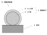
- FIG. 1 is a schematic cross-sectional view showing a first preferred embodiment of the electrode catalyst (core-shell catalyst) of the present invention.
- FIG. 2 is a schematic cross-sectional view showing a second preferred embodiment of the electrode catalyst of the present invention.
- FIG. 3 is a schematic cross-sectional view showing a third preferred embodiment of the electrode catalyst of the present invention.
- FIG. 4 is a schematic sectional view showing a fourth preferred embodiment of the electrode catalyst of the present invention.
- the electrode catalyst 10 of the first embodiment includes a carrier 2 and catalyst particles 3 having a so-called “core-shell structure” formed on the carrier 2. Further, the catalyst particle 3 has a so-called “core-shell structure” including a core part 4 formed on the carrier 2 and a shell part 6 formed on the core part 4. Further, the constituent elements (chemical composition) of the core portion and the constituent elements (chemical composition) of the shell portion 6 are different. In the case of the electrode catalyst 10 shown in FIG. 1, a substantially entire surface of the core portion 4 is covered with the shell portion 6.
- the core portion 4 includes Ti oxide and Pd (zero-valent metal state Pd), and the shell portion 6 includes Pt (zero-valent metal state Pt).
- Pd zero-valent metal state
- Pt zero-valent metal state Pt
- Ti oxide is present in the vicinity of Pt of the shell portion 6, so that the electrode catalyst 10 is equal to or more than this compared to the Pt / Pd / C catalyst.
- the catalyst activity (oxygen reduction activity) and durability can be contributed to cost reduction.
- the electrode catalyst 10A of the second embodiment shown in FIG. 2 has a part of the surface of the core part 4 covered with the shell part 6a, and the surface of the core part 4 is It is in a partially exposed state (for example, a state in which a part 4s of the surface of the core part 4 shown in FIG. 2 is exposed).
- the electrode catalyst 10 ⁇ / b> A shown in FIG. 2 has a shell portion 6 a partially formed on a part of the surface of the core portion 4.
- the shell portion may be formed on at least a part of the surface of the core portion as long as the effects of the present invention can be obtained. Even in this configuration, since the Ti oxide is present in the vicinity of Pt of the shell portion 6a, the electrode catalyst 10A has catalytic activity and durability equivalent to or higher than those of the Pt / Pd / C catalyst. And contribute to cost reduction.
- the main component of the core portion exposed surface 4s (analysis region near the surface measured by XPS) on the surface of the core portion 4 shown in FIG. 2 may be Ti oxide. That is, it may be in a state where the ratio (atom%) of the Ti oxide component is the highest among the constituent components of the core portion exposed surface 4s (analysis region in the vicinity of the surface measured by XPS). . Even in this case, since the Ti oxide exists in the vicinity of Pt of the shell portion 6a on the surface of the catalyst particle 3a, the effect of the present invention can be obtained. As in the electrode catalyst 10A shown in FIG.
- the method for preparing a catalyst having a structure in which the main component of the core portion exposed surface 4s on the surface of the core portion 4 is Ti oxide is not particularly limited, and is prepared by a known method. it can.
- the shell portion 6a is formed on the particles containing Pd and Ti oxide (particles that become the precursor of the core portion), by adopting the UPD method, among the surfaces of the particles containing Pd and Ti oxide
- the shell portion 6a can be selectively formed in a portion where Pd (zero-valent metal state Pd) is exposed.
- Electrode catalyst 10A1 A catalyst (hereinafter referred to as “electrode catalyst 10A1”) can be prepared.
- core part exposed surface 4s among the surfaces of core part 4 consists of Ti oxides, and core part exposed surface 4s among the surfaces of core part 4
- the other surface is preferably made of Pd (zero-valent metal state Pd).
- the electrode catalyst 10B of the third embodiment shown in FIG. 3 has a configuration in which an intermediate shell portion 5b is further disposed between the core portion 4 and the shell portion 6b. have.
- the intermediate shell portion 5b contains Pd.
- the shell part 6b is provided on the intermediate
- the shell part is preferable because it can be formed relatively easily on the intermediate shell part 5b in a good covering state.
- Pd zero-valent metal state Pd
- the intermediate shell portion 5b is more preferably made of only Pd (zero-valent metal state Pd).
- the electrode catalyst 10B has catalytic activity and durability equivalent to or higher than those of the Pt / Pd / C catalyst. And contribute to cost reduction.
- the electrode catalyst 10C shown in FIG. 4 includes an intermediate shell part (intermediate shell part 5c, shell part 5d) on a part of the surface of the core part 4, and A shell part (shell part 6c, shell part 6d) that covers the intermediate shell part is partially formed, and the surface of the core part 4 is partially exposed (for example, one surface of the core part 4 shown in FIG. 4). The portion 4s is exposed). More specifically, in the case of the electrode catalyst 10 ⁇ / b> C shown in FIG.
- an intermediate shell portion 5 c is formed on a part of the surface of the core portion 4, and the shell portion covers almost the entire surface of the intermediate shell portion 5 c. 6c is formed. Further, an intermediate shell portion 5d is formed on another part of the surface of the core portion 4, and a shell portion 6d that covers a part of the surface of the intermediate shell portion 5d is formed.
- a part of surface of the intermediate shell part 5d is coat
- the electrode catalyst 10C is compared with the Pt / Pd / C catalyst. It has equivalent or higher catalytic activity and durability, and can contribute to cost reduction.
- the main component of the core portion exposed surface 4s (analysis region in the vicinity of the surface measured by XPS) on the surface of the core portion 4 shown in FIG. 4 may be Ti oxide. That is, the Ti oxide component ratio (atom%) may be the highest among the constituent components of the core portion exposed surface 4s (analysis region near the surface measured by XPS). Even in this case, since the Ti oxide exists in the vicinity of Pt of the shell portion 6c on the surface of the catalyst particle 3c, the effect of the present invention can be obtained.
- the method for preparing a catalyst having a structure in which the main component of the core portion exposed surface 4s on the surface of the core portion 4 is Ti oxide is not particularly limited, and is prepared by a known method. it can.
- the intermediate shell portion 5c and the intermediate shell portion 5d are formed on particles containing Pd and Ti oxide (particles that serve as a precursor of the core portion)
- the Pd and Ti oxides are changed.
- the intermediate shell portion 5c and the intermediate shell portion 5d can be selectively formed on the surface made of Pd (Pd in a zero-valent metal state) among the surfaces of the contained particles.
- the surface of the intermediate shell portion 5c is adopted by adopting the UPD method.
- the shell portion 6c and the shell portion 6d can be selectively formed on the surface of the intermediate shell portion 5d.
- electrode catalyst 10C1 an electrode catalyst having a structure in which the shell portion 6c is selectively formed on the surface of the intermediate shell portion 5c.
- the core part exposed surface 4s among the surfaces of the core part 4 consists of Ti oxides, and the core part exposed surface 4s among the surfaces of the core part 4 is used.
- the other surface is preferably made of Pd (zero-valent metal state Pd). This makes it easier to selectively form the intermediate shell portion 5c and the intermediate shell portion 5d on the surface other than the core portion exposed surface 4s.
- Pd Pd in a zero-valent metal state
- An intermediate shell portion 5c mainly composed of Pd (zero-valent metal state Pd) and an intermediate shell portion 5d mainly composed of Pd (zero-valent metal state Pd) are formed on the main surface. It becomes a state.
- the electrode catalyst 10C1 since the chemical composition of the contact surface between the core part 4 and the intermediate shell part 5c and the chemical composition of the core part 4 and the intermediate shell part 5d are substantially the same, the core part 4 and the intermediate shell part 5c ( Alternatively, the intermediate shell portion 5d) appears to be integrated. That is, the electrode catalyst 10C1 has substantially the same configuration as the above-described electrode catalyst 10A1 (a modification of the electrode catalyst 10A of the second embodiment).
- the intermediate shell portion 5c containing Pd (zero-valent metal state Pd) as a main component has the highest proportion (atom%) of zero-valent metal state among the constituent components of the intermediate shell portion 5c. State.
- the intermediate shell portion 5d whose main component is Pd (zero-valent metal state Pd) is a state in which the proportion (atom%) of the zero-valent metal state Pd is the highest among the constituent components of the intermediate shell portion 5d.
- the electrode catalyst 10 shown in FIG. 1, the electrode catalyst 10A shown in FIG. 2, the electrode catalyst 10B shown in FIG. 3, and the electrode catalyst 10C shown in FIG. 4 will be described.
- the shell portion 6 (6a, 6b, 6c) is preferably composed only of Pt (zero-valent metal state Pt).
- Pt zero-valent metal state Pt
- the “Ti oxide” contained in the core portion 4 is TiO 2 having high chemical stability.
- the electrode catalysts 10, 10A, 10B, and 10C preferably satisfy the following conditions from the viewpoint of more reliably obtaining the effects of the present invention. That is, the electrode catalysts 10, 10A, 10B, and 10C have a ratio of Pt (zero-valent metal state Pt) in the analysis region near the surface when the surface vicinity is analyzed by X-ray photoelectron spectroscopy (XPS).
- Pt zero-valent metal state Pt
- R1 Pt (atom%), the ratio R1 Pd (atom%) of Pd (zero-valent metal state), and the ratio R1 Ti (atom%) of Ti derived from the Ti oxide are expressed by the following formula (1) It is preferable that the condition of 0.15 ⁇ ⁇ R1 Ti / (R1 Pt + R1 Pd + R1 Ti ) ⁇ ⁇ 0.75 (1)
- the inventors of the present invention have a structure (Ti oxide) that satisfies the condition of the above equation (1) for the chemical composition of the analysis region in the vicinity of the surfaces of the catalyst particles 3, 3a, 3b, 3c of the electrode catalysts 10, 10A, 10B, 10C. It has been found that the effect of the present invention can be obtained more reliably by adopting a configuration in which the ratio of (2) is relatively high.
- the present inventors have found that the presence of Ti oxide satisfying the above formula (1) on or near the surfaces of the catalyst particles 3, 3a, 3b, 3c It is presumed that the oxygen reduction reaction on the Pt of the shell parts 6, 6a, 6b, 6c, 6d of the particles 3, 3a, 3b, 3c is promoted. For example, when Ti oxide is present in the vicinity of Pt in the shell portion, the generated water generated by the reduction reaction of oxygen on Pt can quickly move from the Pt to the Ti oxide side. It is speculated that the reduction reaction is promoted.
- the value of ⁇ R1Ti / ( R1Pt + R1Pd + R1Ti ) ⁇ is a viewpoint that more reliably improves the catalyst activity (particularly, the initial Pt mass activity described later) compared to Pt / Pd / C. Is preferably 0.15 to 0.50, more preferably 0.25 to 0.50, and still more preferably 0.35 to 0.50. Furthermore, the value of ⁇ R1 Ti / (R1 Pt + R1 Pd + R1 Ti ) ⁇ is higher than that of Pt / Pd / C in terms of durability (particularly for “initial ECSA before evaluation test” in the durability evaluation described later). From the viewpoint of more reliably improving the “retention rate of ECSA after evaluation test”, it is preferably 0.15 to 0.50, and more preferably 0.15 to 0.40.
- the X-ray photoelectron spectroscopy is performed under the following analysis conditions (A1) to (A5).
- A2) Photoelectron extraction accuracy: ⁇ 75 ° C.
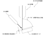
- the photoelectron extraction accuracy ⁇ of (A2) is, as shown in FIG. 5, the X-ray emitted from the X-ray source 32 is irradiated to the sample set on the sample stage 34 and is emitted from the sample.
- the angle ⁇ when the photoelectron is received by the spectroscope 36 corresponds to the angle between the light receiving axis of the spectrometer 36 and the surface of the sample layer of the sample stage 34.
- the electrode catalysts 10, 10A, 10B, and 10C preferably satisfy the following conditions from the viewpoint of more reliably obtaining the effects of the present invention. That is, the electrode catalysts 10, 10A, 10B, and 10C have a ratio of Pt (zero-valent metal state Pt) in the analysis region near the surface when the surface vicinity is analyzed by X-ray photoelectron spectroscopy (XPS). It is preferable that R1 Pt (atom%) and the ratio of Ti derived from Ti oxide R1 Ti (atom%) satisfy the condition of the following formula (2).
- the present inventors have found that the presence of Ti oxide satisfying the above formula (2) on or near the surfaces of the catalyst particles 3, 3a, 3b, 3c It is presumed that the oxygen reduction reaction is promoted on the Pt of the shells of the particles 3, 3a, 3b, 3c. For example, when Ti oxide is present in the vicinity of Pt of the shell parts 6, 6a, 6b, 6c, and 6d, the generated water generated by the oxygen reduction reaction on Pt is promptly formed on the Pt. It is assumed that the oxygen reduction reaction is promoted.
- the value of ⁇ R1 Pt / (R1 Pt + R1 Ti ) ⁇ is compared with Pt / Pd / C from the viewpoint of more reliably improving the catalytic activity (particularly, the initial Pt mass activity described later). 0.25 to 0.60, more preferably 0.35 to 0.60, still more preferably 0.50 to 0.60. Further, the value of ⁇ R1 Pt / (R1 Pt + R1 Ti ) ⁇ is the durability (particularly the maintenance rate of “ECSA after evaluation test” with respect to “initial ECSA before evaluation test” in durability evaluation described later). From the viewpoint of improving more reliably, it is preferably 0.25 to 0.60, more preferably 0.25 to 0.55.
- the XPS in the equation (2) is also measured under the conditions (A1) to (A6) described above.
- R1 Pt in the formula (1) or the formula (2) is preferably 19 atom% or more.
- the ratio of the part which consists of Pt (0t metal state Pt) with high catalytic activity on the surface of the electrode catalyst 10, 10A, 10B, 10C can be sufficiently secured, and the effect of the present invention can be obtained more reliably. be able to.
- R1 Pt is more preferably 30 atom% or more, and further preferably 30 atom% to 47 atom%.
- the ratio R1 Pd of Pd (Pd in a zero-valent metal state) in the formula (1) is preferably 36 atom% or less.
- the ratio of the portion made of Pd (zero-valent metal state Pd) on the surfaces of the electrode catalysts 10, 10A, 10B, and 10C increases, and the elution of Pd can be more reliably suppressed. . Therefore, the effect of the present invention can be obtained more reliably, for example, the durability (particularly, the maintenance rate of “ECSA after evaluation test” with respect to “initial ECSA before evaluation test” in durability evaluation described later) is further improved. It becomes like this.
- the core portion contains sufficient Pd.
- R1 Pd is more preferably 9 atom% to 36 atom%, and 17 atom % To 36 atom% is more preferable.
- the electrode catalyst 10, 10A, 10B, 10C are preferably R1 Ti in the formula (1) or Formula (2) is 18atom% ⁇ 71atom%. Further, from the same viewpoint, R1 Ti is further preferably 18atom% ⁇ 50atom%.
- the electrode catalysts 10, 10A, 10B, and 10C preferably have a Ti loading ratio L Ti (wt%) derived from Ti oxide measured by ICP emission analysis of 4.7 wt% or more.
- L Ti a Ti loading ratio derived from Ti oxide measured by ICP emission analysis of 4.7 wt% or more.
- the Ti loading rate L Ti (wt%) is preferably 9.5 wt% or less, and 9.0 wt% The following is more preferable.
- the Pt loading rate L Pt (wt%) and the Pd loading rate L Pd (wt%) measured by ICP emission analysis are the conditions of the following formula (3). Is preferably satisfied. L Pt / L Pd ⁇ 0.30 (3)
- the electrode catalysts 10, 10A, 10B, and 10C have an average crystallite size of 3 to 35.0 nm measured by powder X-ray diffraction (XRD). Is preferred. It is preferable that the average value of the crystallite size is 3 nm or more because it tends to be easier to form particles that will become the core portion 4 on the carrier. Furthermore, it is preferable that the average value of the crystallite size is 35.0 nm or less, because it becomes easier to form the particles serving as the core portion on the carrier in a highly dispersed state. From the same viewpoint, the average value of the crystallite size of the catalyst particles measured by powder X-ray diffraction (XRD) is more preferably 3 to 20 nm, and further preferably 3 nm or more and less than 20 nm.
- XRD powder X-ray diffraction
- a preferable range is appropriately set according to the design concept of the electrode catalyst. Further, the preferred ranges of the thicknesses of the intermediate shell portions 5b, 5c, and 5d are appropriately set according to the design concept of the electrode catalyst. For example, when it is intended to minimize the amount of Pt used to form the shell parts 6, 6 a, 6 b, 6 c, 6 d, it is a layer composed of one atom (one atomic layer). In this case, the thickness of the shell parts 6, 6a, 6b, 6c, 6d is as follows when the metal elements constituting the shell parts 6, 6a, 6b, 6c, 6d are one kind. The thickness is preferably equivalent to twice the diameter of one atom of the metal element (when approximating a sphere).
- a layer composed of one atom two or more kinds of atoms are juxtaposed on the surface of the core part 4. And a thickness corresponding to one atomic layer formed in this manner.
- the thickness is preferably 1 to 5 nm, and more preferably 2 to 10 nm.
- the shell parts 6, 6a, 6b, 6c, 6d contain Pt (Pt in a zero-valent metal state).
- the shell parts 6, 6a, 6b, 6c, and 6d are mainly composed of Pt (zero-valent metal state Pt) (preferably 50 wt%). More preferably, it is configured as 80 wt% or more, more preferably 90 wt% or more), and more preferably composed of Pt (zero-valent metal state Pt).
- the “average particle diameter” refers to an average value of the diameters of particles composed of an arbitrary number of particle groups, as observed with an electron micrograph.
- the thickness of the intermediate shell portions 5b, 5c, and 5d is preferably equal to or less than the thickness of the shell portion 6. This is preferable because the amount of Pd used can be reduced and the amount of Pd eluted when used as an electrode catalyst can be reduced.
- the intermediate shell portions 5b, 5c, 5d contain Pd (zero-valent metal state Pd).
- the intermediate shell portion 5 is mainly composed of Pd (zero-valent metal state Pd) (preferably 50 wt% or more, more preferably 80 wt%). As described above, it is preferably configured as 90 wt% or more, and more preferably configured from Pd (Pd in a zero-valent metal state).
- the carrier 2 is not particularly limited as long as it can carry a composite composed of the core part 4, the shell parts 6, 6a, 6b, 6c, 6d and the intermediate shell parts 5b, 5c, 5d and has a large surface area. Not. Furthermore, it is preferable that the support
- carrier 2 has a favorable dispersibility in the composition for gas diffusion electrode formation containing the electrode catalysts 10, 10A, 10B, and 10C, and has the outstanding electroconductivity.
- Carrier 2 is glassy carbon (GC), fine carbon, carbon black, graphite, carbon fiber, activated carbon, pulverized product of activated carbon, carbon nanofiber, carbon nanotube, etc., or glass or ceramics material such as oxide. It can be adopted as appropriate.
- a carbon-based material is preferable from the viewpoint of the adsorptivity with the core portion 4 and the BET specific surface area of the carrier 2.
- conductive carbon is preferable, and as the conductive carbon, conductive carbon black is particularly preferable. Examples of the conductive carbon black include trade names “Ketjen Black EC300J”, “Ketjen Black EC600”, “Carbon EPC” and the like (manufactured by Lion Chemical Co., Ltd.).
- the core part 4 is not particularly limited as long as it is configured to include Ti oxide and Pd (zero-valent metal state Pd).
- Pd zero-valent metal state Pd
- the electrode catalyst of the present invention has the electrode catalyst 10 shown in FIG. 1, the electrode catalyst 10A shown in FIG. 2, the electrode catalyst 10B shown in FIG. And the state in which at least 2 types of 10 C of electrode catalysts shown in FIG. 4 were mixed may be sufficient (not shown).
- the shell portion 6c and the shell portion 6d are separated from the same core portion 4 as in the electrode catalyst 10C of the fourth embodiment shown in FIG. May be mixed.
- the electrode catalyst of the present invention may be in a state where only the shell portion 6c shown in FIG. 4 is formed on the same core portion 4 within the range where the effects of the present invention can be obtained. Only the shell portion 6 d shown in FIG. 4 may be formed on the portion 4.
- the electrode catalyst 1 includes the electrode catalyst 10, the electrode catalyst 10A, the electrode catalyst 10B, and the electrode catalyst 10C on the support 2. In addition to at least one kind, a state in which “particles of only the core part 4 not covered with the shell part 6 (6a, 6b, 6c, 6d)” are supported (not shown) may be included. Furthermore, within the range where the effects of the present invention can be obtained, the electrode catalyst 1 includes, in addition to at least one of the above-described electrode catalyst 10, electrode catalyst 10A, electrode catalyst 10B, and electrode catalyst 10C.
- the electrode catalyst 1 includes, in addition to at least one of the above-described electrode catalyst 10, electrode catalyst 10A, electrode catalyst 10B, and electrode catalyst 10C. “Particles of only the core part 4 not covered with the shell part 6 (6a, 6b, 6c, 6d)” and “particles composed only of the constituent elements of the shell part 6 (6a, 6b, 6c, 6d)” However, the state carried independently may be included (not shown).
- the method for producing the electrode catalyst 10, 10A includes a “core particle forming step” in which core particles containing Pd and Ti oxide are formed on a carrier, and at least a surface of the core particles obtained through the core particle forming step. It includes a “shell portion forming step” in which the shell portions 6 and 6 a are partially formed.
- the electrode catalyst 10, 10 ⁇ / b> A is manufactured by sequentially supporting the core part 4 and the shell parts 6, 6 a constituting the catalyst particles 3, 3 a on the carrier 2.
- the method for producing the electrode catalyst 10 or 10A is not particularly limited as long as the method can support the catalyst particles 3 and 3a on the carrier 2.
- an impregnation method in which a solution containing a catalyst component is brought into contact with the support 2 and the support 2 is impregnated with the catalyst component
- a liquid phase reduction method in which a reducing agent is added to the solution containing the catalyst component
- an underpotential precipitation method examples of production methods that employ electrochemical deposition methods such as UPD), chemical reduction methods, reduction deposition methods using adsorbed hydrogen, surface leaching methods of alloy catalysts, displacement plating methods, sputtering methods, vacuum deposition methods, etc. it can.
- the raw materials and the mixing ratios of the raw materials are combined by combining the above-mentioned known methods so as to satisfy the above-mentioned preferred conditions such as formulas (1), (2), and (3). It is preferable to adjust the reaction conditions of the synthesis reaction. Also in the “shell part forming step”, the raw materials and their blends are combined by combining the above-mentioned known methods so as to satisfy the above-mentioned preferred conditions such as formulas (1), (2), and (3). It is preferable to adjust the ratio, synthesis reaction conditions, and the like.
- the electrode catalyst 10, 10A so as to satisfy the above-mentioned preferred conditions such as the formulas (1), (2), (3), for example, the chemical composition of the product (catalyst) Analyze the structure using various known analytical methods, feed back the results of the analysis to the manufacturing process, and prepare and select the raw materials to be selected, the mixing ratio of the raw materials, the synthetic reaction to be selected, the reaction conditions for the synthetic reaction, etc.
- the method of changing is given.
- the method for producing electrode catalysts 10B and 10C includes a “core particle forming step” in which core particles containing Pd and Ti oxide are formed on a carrier, and at least the surface of the core particles obtained through the core particle forming step.
- the electrode catalysts 10B and 10C are manufactured by sequentially supporting the core part 4, the intermediate shell parts 5b, 5c and 5d, and the shell parts 6b, 6c and 6d constituting the catalyst particles 3b and 3c on the carrier 2.
- the method for producing the electrode catalysts 10B and 10C is not particularly limited as long as the catalyst particles 3b and 3c can be supported on the carrier 2.
- an impregnation method in which a solution containing a catalyst component is brought into contact with the support 2 and the support 2 is impregnated with the catalyst component
- a liquid phase reduction method in which a reducing agent is added to the solution containing the catalyst component
- an underpotential precipitation method examples of production methods that employ electrochemical deposition methods such as UPD), chemical reduction methods, reduction deposition methods using adsorbed hydrogen, surface leaching methods of alloy catalysts, displacement plating methods, sputtering methods, vacuum deposition methods, etc. it can.
- the raw materials In the “core particle forming step”, the raw materials, the mixing ratio of the raw materials, It is preferable to adjust the reaction conditions of the synthesis reaction. Also, in the “intermediate shell portion forming step”, the raw materials are obtained by combining the above-described known methods so as to satisfy the above-mentioned preferred conditions such as formulas (1), (2), and (3). It is preferable to adjust the blending ratio, synthesis reaction conditions, and the like. Furthermore, also in the “shell part forming step”, the raw materials and their blends are combined by combining the above-mentioned known methods so as to satisfy the above-mentioned preferred conditions such as formulas (1), (2), and (3). It is preferable to adjust the ratio, synthesis reaction conditions, and the like.
- the electrode catalysts 10B and 10C so as to satisfy the above-described preferable conditions such as the formulas (1), (2), and (3), for example, the chemical composition and structure of the product (catalyst)
- the analysis results obtained are fed back to the manufacturing process, and the raw materials to be selected, the mixing ratio of the raw materials, the synthesis reaction to be selected, the reaction conditions for the synthesis reaction, etc. are prepared and changed. And how to do it.
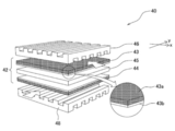
- FIG. 6 shows a gas diffusion electrode forming composition containing the electrode catalyst of the present invention, a gas diffusion electrode produced using this gas diffusion electrode forming composition, and a membrane / electrode assembly comprising this gas diffusion electrode
- FIG. 2 is a schematic diagram showing a preferred embodiment of a fuel cell stack including a MEMBRANE ELECTRODE ASSEMBLY (hereinafter abbreviated as “MEA” as necessary).
- MEA MEMBRANE ELECTRODE ASSEMBLY
- the fuel cell stack 40 includes an MEA 42 including an anode 43 that is a gas diffusion electrode, a cathode 44 that is a gas diffusion electrode, and an electrolyte membrane 45 disposed between these electrodes.
- the fuel cell stack 40 has a configuration in which the MEA 42 is sandwiched between a separator 46 and a separator 48.
- the gas diffusion electrode forming composition, the anode 43 and the cathode 44, and the MEA 42, which are members of the fuel cell stack 40 including the electrode catalyst of the present invention, will be described.
- the electrode catalyst of the present invention can be used as a so-called catalyst ink component to form the gas diffusion electrode forming composition of the present invention.
- the gas diffusion electrode forming composition of the present invention is characterized by containing the electrode catalyst of the present invention.
- the composition for forming a gas diffusion electrode contains the electrode catalyst and an ionomer solution as main components.
- the composition of the ionomer solution is not particularly limited.
- the ionomer solution may contain a polymer electrolyte having hydrogen ion conductivity, water, and alcohol.
- the polymer electrolyte contained in the ionomer solution is not particularly limited.
- the polymer electrolyte can be exemplified by a perfluorocarbon resin having a known sulfonic acid group or carboxylic acid group.
- a perfluorocarbon resin having a known sulfonic acid group or carboxylic acid group.
- polymer electrolytes having hydrogen ion conductivity Nafion (registered trademark, manufactured by DuPont), Aciplex (registered trademark, manufactured by Asahi Kasei Co., Ltd.), Flemion (registered trademark, manufactured by Asahi Glass Co., Ltd.) It can be illustrated.
- the composition for forming a gas diffusion electrode can be prepared by mixing, crushing, and stirring an electrode catalyst and an ionomer solution.
- the composition for forming a gas diffusion electrode can be prepared using a pulverizing mixer such as a ball mill or an ultrasonic disperser.
- the pulverization conditions and the stirring conditions when operating the pulverization mixer can be appropriately set according to the mode of the gas diffusion electrode forming composition.
- Each composition of the electrode catalyst, water, alcohol, and polymer electrolyte having hydrogen ion conductivity contained in the gas diffusion electrode forming composition has a good dispersion state of the electrode catalyst, and the electrode catalyst is gas diffused. It is appropriately set so that the entire catalyst layer of the electrode can be widely spread and the power generation performance of the fuel cell can be improved.
- the anode 43 which is a gas diffusion electrode, has a configuration including a gas diffusion layer 43a and a catalyst layer 43b formed on the surface of the gas diffusion layer 43a on the electrolyte membrane 45 side.
- the cathode 44 has a gas diffusion layer (not shown) and a catalyst layer (not shown) formed on the surface of the gas diffusion layer on the electrolyte membrane 45 side.
- the electrode catalyst of the present invention may be contained in at least one of the anode 43 and the cathode 44. Further, it is preferably contained in the catalyst layers of both the anode 43 and the cathode 44.
- the gas diffusion electrode of this invention can be used as an anode and can also be used as a cathode. Since the gas diffusion electrode (anode 43 and / or cathode 44) according to the present invention includes the electrode catalyst of the present invention, it is compared with the gas diffusion electrode including the Pt / Pd / C catalyst. It becomes easy to have a structure that has catalytic activity (polarization characteristics) and durability equal to or higher and can contribute to cost reduction.
- the catalyst layer 43b is a layer in the anode 43 where a chemical reaction is performed in which the hydrogen gas sent from the gas diffusion layer 43a is dissociated into hydrogen ions by the action of the electrode catalyst 10 contained in the catalyst layer 43b.
- the catalyst layer 43b includes, in the cathode 44, the catalyst 10 for an electrode in which the air (oxygen gas) sent from the gas diffusion layer 43a and the hydrogen ions that have moved through the electrolyte membrane from the anode 43 are contained in the catalyst layer 43b. It is a layer in which a chemical reaction is performed by bonding.
- the catalyst layer 43b is formed using the gas diffusion electrode forming composition.
- the catalyst layer 43b preferably has a large surface area so that the reaction between the electrode catalyst 10 and the hydrogen gas or air (oxygen gas) sent from the gas diffusion layer 43a can be sufficiently performed.
- the catalyst layer 43b is preferably formed so as to have a uniform thickness throughout. The thickness of the catalyst layer 43b may be appropriately adjusted and is not limited, but is preferably 2 to 200 ⁇ m.
- the gas diffusion layer provided in the anode 43 serving as the gas diffusion electrode and the cathode 44 serving as the gas diffusion electrode is introduced into the gas flow path formed between the separator 46 and the anode 43 from the outside of the fuel cell stack 40.
- This is a layer provided for diffusing the hydrogen gas and the air (oxygen gas) introduced into the gas flow path formed between the separator 48 and the cathode 44 into each catalyst layer.
- the gas diffusion layer has a role of supporting the catalyst layer and immobilizing it on the surface of the gas diffusion electrode.
- the gas diffusion layer has a function / structure that allows hydrogen gas or air (oxygen gas) to pass through well and reach the catalyst layer. For this reason, it is preferable that the gas diffusion layer has water repellency.
- the gas diffusion layer has a water repellent component such as polyethylene terephthalate (PTFE).
- the member which can be used for the gas diffusion layer is not particularly limited, and a known member used for the gas diffusion layer of the fuel cell electrode can be used.
- a known member used for the gas diffusion layer of the fuel cell electrode can be used.
- carbon paper, carbon paper as a main raw material, and carbon powder, ion-exchanged water as optional components, and a secondary material made of polyethylene terephthalate dispersion as a binder are applied to carbon paper.
- the anode 43 that is a gas diffusion electrode and the cathode 44 that is a gas diffusion electrode may include an intermediate layer (not shown) between the gas diffusion layer and the catalyst layer.
- the gas diffusion electrode of this invention should just be manufactured so that the electrode catalyst of this invention may become a structural component of a catalyst layer, and a manufacturing method is not specifically limited, A well-known manufacturing method is employable.
- the gas diffusion electrode is formed by applying a gas diffusion electrode forming composition containing an electrode catalyst, a polymer electrolyte having hydrogen ion conductivity, and an ionomer to the gas diffusion layer, and You may manufacture through the process of drying the gas diffusion layer with which the composition was apply
- An MEA 42 that is a preferred embodiment of the MEA of the present invention shown in FIG. 6 has a configuration including an anode 43, a cathode 44, and an electrolyte membrane 45.
- the MEA 42 has a configuration in which at least one of the anode 43 and the cathode 44 includes a gas diffusion electrode containing the electrode catalyst of the present invention. Since the MEA 42 includes the gas diffusion electrode according to the present invention, the MEA 42 has battery characteristics and durability equivalent to or higher than those of the MEA including the Pt / Pd / C catalyst in the gas diffusion electrode, and is low It becomes easy to set it as the structure which can contribute to cost reduction.
- the MEA 42 can be manufactured by laminating the anode 43, the electrolyte 300, and the cathode 44 in this order, and then press-bonding them.
- a fuel cell stack 40 which is a preferred embodiment of the fuel cell stack of the present invention shown in FIG. 6 has a configuration in which a separator 46 is disposed outside the anode 43 of the MEA 42 and a separator 48 is disposed outside the cathode 44.
- One unit cell single cell
- this unit cell single cell
- the fuel cell stack 40 includes the MEA 42 according to the present invention
- the fuel cell stack 40 has a cell characteristic equal to or higher than that of the fuel cell stack including at least one MEA including the Pt / Pd / C catalyst in the gas diffusion electrode.
- the fuel cell system is completed by attaching and assembling peripheral devices to the fuel cell stack 40.
- This Pt / Pd / Pd + TiO 2 / C powder is an intermediate composed of Pd (zero-valent metal state Pd) in the surface of the following Pd / Pd + TiO 2 / C powder by adjusting the conditions of the UPD method.
- This is a powder in which a shell portion made of Pt is selectively formed in a layer.
- the present inventors presume that the electrode catalyst 10C1 is a modified embodiment of the electrode catalyst 10C of the fourth embodiment shown in FIG.
- the electrode catalyst 10C1 has substantially the same configuration as the electrode catalyst 10A1, which is a modification of the electrode catalyst 10A of the second embodiment shown in FIG.
- the present inventors have a configuration of precursor particles before the shell portions 6c and 6d are formed in the electrode catalyst 10C1 which is a modification of the electrode catalyst 10C of the fourth embodiment shown in FIG. I guess.
- Pd + TiO 2 / C powder with a core particle composed of Pd and Ti oxide (TiO 2 ) supported on carbon black powder ⁇ trade name “NE-H002T0-DE”, manufactured by NE CHEMCAT) ⁇ Prepared.
- This Pd + TiO 2 / C powder was prepared by heat-treating a powder containing a commercially available carbon black powder (specific surface area 750 to 850 m 2 / g), a commercially available Ti compound, and a Pd compound in a reducing atmosphere. is there.
- the core particles of the Pd + TiO 2 / C powder were composed of Pd and Ti oxide (TiO 2 ).
- the Pt loading rate L Pt (wt%), the Pd loading rate L Pd (wt%), and the Ti loading rate L Ti (wt%) were measured by the following methods.
- the electrode catalyst of Example 1 was immersed in aqua regia to dissolve the metal. Next, insoluble component carbon was removed from the aqua regia. Next, aqua regia without carbon was analyzed by ICP. The results of ICP analysis are shown in Table 1.
- Example 2 to Example 7 XPS analysis results (R1 Pt , R1 Pd , R1 Ti ) of the surface of the electrode catalyst shown in Table 1, ICP analysis results (L Pt , L Pd , L Ti ) of the entire catalyst particles, XPS analysis of the surface of the catalyst particles
- electrode catalysts of Examples 2 to 7 were produced.
- XPS analysis and ICP analysis were also performed under the same conditions as in Example 1.
- Pd / C powder [Core particle supported carbon “Pd / C” powder] Pd / C powder ⁇ trade name “NE-H0200-DE”, manufactured by NE CHEMCAT) ⁇ in which core particles made of Pd were supported on carbon black powder was prepared.
- This Pd / C powder was prepared as follows. First, in a liquid obtained by preparing a liquid mixture of commercially available carbon black powder (specific surface area 750 to 850 m 2 / g), sodium tetrachloropalladium (II) and water, and adding a reducing agent to this. Then, palladium ions were reduced to obtain a powder in which Pd particles were supported on a carbon black powder.
- the powder in which the Pd particles are supported on the carbon black powder is subjected to a heat treatment in a reducing atmosphere similar to the case where the core particle-supported carbon “Pd + TiO 2 / C” powder of Example 1 is prepared.
- C powder was obtained.
- XPS analysis and ICP analysis were performed under the same conditions as those of the electrode catalyst of Example 1. The results are shown in Table 1.
- a shell part layer made of Pt was formed on at least a part of the surface of the core part particle made of Pd. It was confirmed that the catalyst particles having the core-shell structure were supported on a conductive carbon support.
- Electrode About 8.0 mg of electrode catalyst powder of Examples 1 to 7 and Comparative Example 1 was weighed and placed in a sample bottle together with 2.5 mL of ultrapure water. Mixing while irradiating with sound waves, an electrode catalyst slurry (suspension) was prepared. Next, 10.0 mL of ultrapure water and 20 ⁇ L of a 10 wt% Nafion (registered trademark) aqueous dispersion (trade name “DE1020CS” manufactured by Wako Chemical Co., Ltd.) are mixed in another container to prepare a Nafion-ultrapure aqueous solution. did.
- a 10 wt% Nafion (registered trademark) aqueous dispersion trade name “DE1020CS” manufactured by Wako Chemical Co., Ltd.
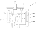
- FIG. 7 is a schematic diagram showing a schematic configuration of a rotating disk electrode measuring apparatus 50 used in the rotating disk electrode method (RDE method).
- the rotating disk electrode measuring apparatus 50 mainly includes a measurement cell 51, a reference electrode RE, a counter electrode CE, and a rotating disk electrode WE. Furthermore, when evaluating a catalyst, electrolyte solution ES is put into the measurement cell 51.
- the measurement cell 51 has a substantially cylindrical shape having an opening on the upper surface, and a fixing member 52 for the rotating disk electrode WE that also serves as a lid capable of gas sealing is disposed in the opening.
- a gas sealable opening for fixing the electrode main body portion of the rotating disk electrode WE while being inserted into the measurement cell 51 is provided at the center of the fixing member 52.
- a substantially L-shaped Lugin tube 53 is arranged next to the measurement cell 51.
- one end portion of the Luggin tube 53 has a Luggin capillary structure, and is inserted into the measurement cell 51, so that the electrolyte ES of the measurement cell 51 also enters the Luggin tube 53.
- the other end of the Lugin tube 53 has an opening, and the reference electrode RE is inserted into the Lugin tube 53 through the opening.
- “Model HSV110” manufactured by Hokuto Denko Co., Ltd. was used as the rotating disk electrode measuring device 50.
- an Ag / AgCl saturated electrode was used as the reference electrode RE, a Pt mesh with Pt black was used as the counter electrode CE, and an electrode having a diameter of 5.0 mm ⁇ and an area of 19.6 mm 2 was used as the rotating disk electrode WE. . Furthermore, using the HCl0 4 of 0.1M as the electrolyte ES.
- CV measurement was performed for 3 cycles in the “triangular wave potential sweep mode” in which the potential (vsRHE) of the rotating disk electrode WE was set to the measurement start potential +119 mV, +50 mV to 1200 mV, and the scanning speed was 20 mV / sec.
- the rotational speed of the rotating disk electrode WE was 1600 rpm.
- the rotating disk electrode was rotated 10 times in “triangular wave potential sweep mode” with a scanning potential of 135 to 1085 mV vs RHE and a scanning speed of 10 mV / sec.
- CV measurement was performed under the condition that the rotational speed of WE was 1600 rpm.
- the current value at the potential of the rotating disk electrode WE + 900 mV vs RHE was recorded.
- the rotational speed of the rotating disk electrode WE was set to 400 rpm, 625 rpm, 900 rpm, 1225 rpm, 2025 rpm, 2500 rpm, and 3025 rpm, respectively, and oxygen reduction (ORR) current measurement was performed for each cycle.
- ORR oxygen reduction
- Pt mass activity (Mass Act) (mA/ ⁇ g-Pt@0.9V) was calculated.
- the results obtained for Examples 1 to 7 and Comparative Example 1 are shown in Table 1.
- Table 1 the Pt mass activity of Examples 1 to 5 and Comparative Example 2 when the Pt mass activity (Mass Act) of Comparative Example 1 (Pt / Pd / C catalyst) is 1.00.
- the relative value of (Mass Act) was shown.
- V-1) [Initial ECSA measurement]
- I Potential sweep process The potential (vsRHE) of the rotating disk electrode WE with respect to the reference electrode RE was swept in a so-called "rectangular wave potential sweep mode" shown in FIG. More specifically, a potential sweep was performed for 6 cycles with the operation shown in (A) to (D) below as one cycle.
- A Potential at start of sweep: +600 mV
- B Sweep from +600 mV to +1000 mV
- C Hold potential at +1000 mV for 3 seconds
- D Sweep from +1000 mV to +600 mV
- E Hold potential at +600 mV 3 seconds.
- the values of the catalyst for electrodes of Example 1 and Examples 2 to 6 [ ⁇ R1 Ti / (R1 Pt + R1 Pd + R1 Ti ) ⁇ are 0.25 to 0.50, ⁇ R1 Ti / (R1 Pt + R1) Ti ) ⁇ value of 0.35 to 0.60] has a Pt mass activity of about 2 to 3 times that of the electrode catalyst of Comparative Example 1 (Pt / Pd / C catalyst). It was revealed that it has excellent catalytic activity. Further, from the results of “the relative value of the retention rate of ESCA” obtained from the initial ECSA value and the ECSA measurement value after 12420 cycles of potential sweep shown in Table 1, the electrodes of Examples 1 to 6 were used.
- the catalyst [ ⁇ R1Ti / ( R1Pt + R1Pd + R1Ti ) ⁇ has a value of 0.15 to 0.50 and ⁇ R1Ti / ( R1Pt + R1Ti ) ⁇ has a value of 0.25 to 0.60].
- the ECSA value and ECSA maintenance rate after the number of potential sweeps of 12420 cycles were equal or higher (about 1.3 times to about 1.5 times). It was revealed that it had excellent durability.
- the electrode catalyst of the present example has equivalent or higher catalytic activity and durability than the Pt / Pd / C catalyst. Furthermore, since the electrode catalyst of this example employs a Ti oxide as a part of the material of the core portion, it has been clarified that the amount of platinum used can be reduced and the cost can be reduced.
- the electrode catalyst of the present invention has equivalent or higher catalytic activity and durability than the Pt / Pd / C catalyst, and can contribute to cost reduction. Accordingly, the present invention is an electrode catalyst that can be applied not only to the electric equipment industry such as fuel cells, fuel cell vehicles, and portable mobiles, but also to energy farms, cogeneration systems, etc. Contribute to development.
Landscapes
- Chemical & Material Sciences (AREA)
- Chemical Kinetics & Catalysis (AREA)
- Electrochemistry (AREA)
- General Chemical & Material Sciences (AREA)
- Engineering & Computer Science (AREA)
- Materials Engineering (AREA)
- Manufacturing & Machinery (AREA)
- Composite Materials (AREA)
- Life Sciences & Earth Sciences (AREA)
- Sustainable Development (AREA)
- Sustainable Energy (AREA)
- Organic Chemistry (AREA)
- Inert Electrodes (AREA)
- Fuel Cell (AREA)
- Catalysts (AREA)
Abstract
Priority Applications (4)
| Application Number | Priority Date | Filing Date | Title |
|---|---|---|---|
| US16/078,306 US20190051910A1 (en) | 2016-02-29 | 2017-01-24 | Electrode catalyst, composition for forming gas diffusion electrode, gas diffusion electrode, membrane-electrode assembly, and fuel cell stack |
| EP17759481.9A EP3425711A1 (fr) | 2016-02-29 | 2017-01-24 | Catalyseur pour électrode, composition pour former une électrode à diffusion de gaz, électrode à diffusion de gaz, ensemble d'électrode à membrane, et empilage de piles à combustible |
| CN201780013797.0A CN108701836A (zh) | 2016-02-29 | 2017-01-24 | 电极用催化剂、气体扩散电极形成用组合物、气体扩散电极、膜电极组件、燃料电池堆 |
| JP2018502590A JPWO2017150009A1 (ja) | 2016-02-29 | 2017-01-24 | 電極用触媒、ガス拡散電極形成用組成物、ガス拡散電極、膜・電極接合体、燃料電池スタック |
Applications Claiming Priority (2)
| Application Number | Priority Date | Filing Date | Title |
|---|---|---|---|
| JP2016-037609 | 2016-02-29 | ||
| JP2016037609 | 2016-02-29 |
Publications (1)
| Publication Number | Publication Date |
|---|---|
| WO2017150009A1 true WO2017150009A1 (fr) | 2017-09-08 |
Family
ID=59743804
Family Applications (1)
| Application Number | Title | Priority Date | Filing Date |
|---|---|---|---|
| PCT/JP2017/002386 Ceased WO2017150009A1 (fr) | 2016-02-29 | 2017-01-24 | Catalyseur pour électrode, composition pour former une électrode à diffusion de gaz, électrode à diffusion de gaz, ensemble d'électrode à membrane, et empilage de piles à combustible |
Country Status (5)
| Country | Link |
|---|---|
| US (1) | US20190051910A1 (fr) |
| EP (1) | EP3425711A1 (fr) |
| JP (1) | JPWO2017150009A1 (fr) |
| CN (1) | CN108701836A (fr) |
| WO (1) | WO2017150009A1 (fr) |
Families Citing this family (1)
| Publication number | Priority date | Publication date | Assignee | Title |
|---|---|---|---|---|
| KR102882441B1 (ko) * | 2022-10-17 | 2025-11-06 | 현대자동차주식회사 | 연료 전지 전극용 촉매, 이의 제조방법 및 이를 포함하는 연료 전지 |
Citations (14)
| Publication number | Priority date | Publication date | Assignee | Title |
|---|---|---|---|---|
| JP2009510705A (ja) * | 2005-08-01 | 2009-03-12 | ブルックヘヴン サイエンス アソシエイツ | プラチナナノ粒子コア上に金の単原子層を含む電極触媒及びその使用 |
| JP2010537033A (ja) * | 2007-08-28 | 2010-12-02 | ビーエーエスエフ ソシエタス・ヨーロピア | 塗料中の光活性TiO2 |
| JP2011072981A (ja) * | 2008-10-30 | 2011-04-14 | Sony Corp | 白金含有触媒及びその製造方法、並びに電極及び電気化学デバイス |
| JP2011162879A (ja) * | 2010-02-04 | 2011-08-25 | Robert Bosch Gmbh | 導電性材料 |
| JP2012120949A (ja) * | 2010-12-06 | 2012-06-28 | Toyota Motor Corp | 白金/パラジウムコアシェル触媒の製造方法 |
| JP2012143753A (ja) * | 2011-01-13 | 2012-08-02 | Samsung Electronics Co Ltd | 活性粒子含有触媒、その製造方法、該触媒を含んだ燃料電池、該活性粒子を含有するリチウム空気電池用電極、及び該電極を含んだリチウム空気電池 |
| JP2013080683A (ja) * | 2011-10-05 | 2013-05-02 | Nissan Motor Co Ltd | 電極触媒 |
| JP2013127869A (ja) * | 2011-12-16 | 2013-06-27 | Univ Of Miyazaki | 燃料電池用白金・チタン酸化物・チタンカーバイド複合触媒及びその製造方法、並びに当該複合触媒を用いた燃料電池用膜・電極接合体 |
| WO2014069208A1 (fr) * | 2012-10-29 | 2014-05-08 | 学校法人同志社 | Catalyseur au platine à structure cœur-écorce, son procédé de fabrication et pile à combustible l'utilisant |
| JP2014514956A (ja) * | 2011-07-25 | 2014-06-26 | トヨタ モーター ヨーロッパ ナームロゼ フェンノートシャップ/ソシエテ アノニム | 高電気化学的安定性及び高費用効率のコア−シェル触媒 |
| JP2014209484A (ja) * | 2014-05-22 | 2014-11-06 | 国立大学法人宮崎大学 | 燃料電池用触媒の製造方法 |
| US20150333337A1 (en) * | 2013-01-16 | 2015-11-19 | Ilika Technologies Ltd | Composite Materials |
| JP2015534244A (ja) * | 2012-10-22 | 2015-11-26 | アウディ アクチェンゲゼルシャフトAudi Ag | 非白金コアを有する白金合金ナノ触媒 |
| US20150372316A1 (en) * | 2013-01-16 | 2015-12-24 | Ilika Technologies Ltd | Composite Materials |
-
2017
- 2017-01-24 CN CN201780013797.0A patent/CN108701836A/zh not_active Withdrawn
- 2017-01-24 EP EP17759481.9A patent/EP3425711A1/fr not_active Withdrawn
- 2017-01-24 JP JP2018502590A patent/JPWO2017150009A1/ja not_active Withdrawn
- 2017-01-24 US US16/078,306 patent/US20190051910A1/en not_active Abandoned
- 2017-01-24 WO PCT/JP2017/002386 patent/WO2017150009A1/fr not_active Ceased
Patent Citations (14)
| Publication number | Priority date | Publication date | Assignee | Title |
|---|---|---|---|---|
| JP2009510705A (ja) * | 2005-08-01 | 2009-03-12 | ブルックヘヴン サイエンス アソシエイツ | プラチナナノ粒子コア上に金の単原子層を含む電極触媒及びその使用 |
| JP2010537033A (ja) * | 2007-08-28 | 2010-12-02 | ビーエーエスエフ ソシエタス・ヨーロピア | 塗料中の光活性TiO2 |
| JP2011072981A (ja) * | 2008-10-30 | 2011-04-14 | Sony Corp | 白金含有触媒及びその製造方法、並びに電極及び電気化学デバイス |
| JP2011162879A (ja) * | 2010-02-04 | 2011-08-25 | Robert Bosch Gmbh | 導電性材料 |
| JP2012120949A (ja) * | 2010-12-06 | 2012-06-28 | Toyota Motor Corp | 白金/パラジウムコアシェル触媒の製造方法 |
| JP2012143753A (ja) * | 2011-01-13 | 2012-08-02 | Samsung Electronics Co Ltd | 活性粒子含有触媒、その製造方法、該触媒を含んだ燃料電池、該活性粒子を含有するリチウム空気電池用電極、及び該電極を含んだリチウム空気電池 |
| JP2014514956A (ja) * | 2011-07-25 | 2014-06-26 | トヨタ モーター ヨーロッパ ナームロゼ フェンノートシャップ/ソシエテ アノニム | 高電気化学的安定性及び高費用効率のコア−シェル触媒 |
| JP2013080683A (ja) * | 2011-10-05 | 2013-05-02 | Nissan Motor Co Ltd | 電極触媒 |
| JP2013127869A (ja) * | 2011-12-16 | 2013-06-27 | Univ Of Miyazaki | 燃料電池用白金・チタン酸化物・チタンカーバイド複合触媒及びその製造方法、並びに当該複合触媒を用いた燃料電池用膜・電極接合体 |
| JP2015534244A (ja) * | 2012-10-22 | 2015-11-26 | アウディ アクチェンゲゼルシャフトAudi Ag | 非白金コアを有する白金合金ナノ触媒 |
| WO2014069208A1 (fr) * | 2012-10-29 | 2014-05-08 | 学校法人同志社 | Catalyseur au platine à structure cœur-écorce, son procédé de fabrication et pile à combustible l'utilisant |
| US20150333337A1 (en) * | 2013-01-16 | 2015-11-19 | Ilika Technologies Ltd | Composite Materials |
| US20150372316A1 (en) * | 2013-01-16 | 2015-12-24 | Ilika Technologies Ltd | Composite Materials |
| JP2014209484A (ja) * | 2014-05-22 | 2014-11-06 | 国立大学法人宮崎大学 | 燃料電池用触媒の製造方法 |
Also Published As
| Publication number | Publication date |
|---|---|
| JPWO2017150009A1 (ja) | 2018-12-20 |
| CN108701836A (zh) | 2018-10-23 |
| EP3425711A1 (fr) | 2019-01-09 |
| US20190051910A1 (en) | 2019-02-14 |
Similar Documents
| Publication | Publication Date | Title |
|---|---|---|
| JP5887453B1 (ja) | 電極用触媒、ガス拡散電極形成用組成物、ガス拡散電極、膜・電極接合体、燃料電池スタック | |
| JP6009112B1 (ja) | 電極用触媒、ガス拡散電極形成用組成物、ガス拡散電極、膜・電極接合体、燃料電池スタック、電極用触媒の製造方法、及び、複合粒子 | |
| WO2017150009A1 (fr) | Catalyseur pour électrode, composition pour former une électrode à diffusion de gaz, électrode à diffusion de gaz, ensemble d'électrode à membrane, et empilage de piles à combustible | |
| WO2017150010A1 (fr) | Catalyseur destiné à une électrode, composition destinée à former une électrode à diffusion de gaz, électrode à diffusion de gaz, ensemble électrode à membrane, et empilement de piles a combustible | |
| WO2018180676A1 (fr) | Catalyseur d'électrode, composition de formation d'électrode à diffusion gazeuse, électrode à diffusion gazeuse, ensemble film-électrode, et empilement de piles à combustible | |
| JP6946112B2 (ja) | 電極用触媒、ガス拡散電極形成用組成物、ガス拡散電極、膜・電極接合体、燃料電池スタック | |
| WO2018180675A1 (fr) | Catalyseur pour électrode, composition de formation d'électrode à diffusion gazeuse, électrode à diffusion gazeuse, ensemble film-électrode, et empilement de piles à combustible | |
| JP2020074260A (ja) | 電極用触媒、ガス拡散電極形成用組成物、ガス拡散電極、膜・電極接合体、燃料電池スタック | |
| JP2017157551A (ja) | 電極用触媒、ガス拡散電極形成用組成物、ガス拡散電極、膜・電極接合体、燃料電池スタック | |
| WO2018159524A1 (fr) | Catalyseur d'électrode, composition de formation d'électrode à diffusion gazeuse, électrode à diffusion gazeuse, ensemble membrane-électrode et empilement de piles à combustible | |
| JP2020074259A (ja) | 電極用触媒、ガス拡散電極形成用組成物、ガス拡散電極、膜・電極接合体、燃料電池スタック |
Legal Events
| Date | Code | Title | Description |
|---|---|---|---|
| WWE | Wipo information: entry into national phase |
Ref document number: 2018502590 Country of ref document: JP |
|
| NENP | Non-entry into the national phase |
Ref country code: DE |
|
| WWE | Wipo information: entry into national phase |
Ref document number: 2017759481 Country of ref document: EP |
|
| ENP | Entry into the national phase |
Ref document number: 2017759481 Country of ref document: EP Effective date: 20181001 |
|
| 121 | Ep: the epo has been informed by wipo that ep was designated in this application |
Ref document number: 17759481 Country of ref document: EP Kind code of ref document: A1 |