WO2017150066A1 - 缶用鋼板およびその製造方法 - Google Patents
缶用鋼板およびその製造方法 Download PDFInfo
- Publication number
- WO2017150066A1 WO2017150066A1 PCT/JP2017/003748 JP2017003748W WO2017150066A1 WO 2017150066 A1 WO2017150066 A1 WO 2017150066A1 JP 2017003748 W JP2017003748 W JP 2017003748W WO 2017150066 A1 WO2017150066 A1 WO 2017150066A1
- Authority
- WO
- WIPO (PCT)
- Prior art keywords
- less
- depth position
- rolling
- cans
- temperature
- Prior art date
- Legal status (The legal status is an assumption and is not a legal conclusion. Google has not performed a legal analysis and makes no representation as to the accuracy of the status listed.)
- Ceased
Links
Classifications
-
- C—CHEMISTRY; METALLURGY
- C21—METALLURGY OF IRON
- C21D—MODIFYING THE PHYSICAL STRUCTURE OF FERROUS METALS; GENERAL DEVICES FOR HEAT TREATMENT OF FERROUS OR NON-FERROUS METALS OR ALLOYS; MAKING METAL MALLEABLE, e.g. BY DECARBURISATION OR TEMPERING
- C21D8/00—Modifying the physical properties of ferrous metals or ferrous alloys by deformation combined with, or followed by, heat treatment
- C21D8/02—Modifying the physical properties of ferrous metals or ferrous alloys by deformation combined with, or followed by, heat treatment during manufacturing of plates or strips
- C21D8/0247—Modifying the physical properties of ferrous metals or ferrous alloys by deformation combined with, or followed by, heat treatment during manufacturing of plates or strips characterised by the heat treatment
- C21D8/0263—Modifying the physical properties of ferrous metals or ferrous alloys by deformation combined with, or followed by, heat treatment during manufacturing of plates or strips characterised by the heat treatment following hot rolling
-
- C—CHEMISTRY; METALLURGY
- C22—METALLURGY; FERROUS OR NON-FERROUS ALLOYS; TREATMENT OF ALLOYS OR NON-FERROUS METALS
- C22C—ALLOYS
- C22C38/00—Ferrous alloys, e.g. steel alloys
- C22C38/002—Ferrous alloys, e.g. steel alloys containing In, Mg, or other elements not provided for in one single group C22C38/001 - C22C38/60
-
- C—CHEMISTRY; METALLURGY
- C22—METALLURGY; FERROUS OR NON-FERROUS ALLOYS; TREATMENT OF ALLOYS OR NON-FERROUS METALS
- C22C—ALLOYS
- C22C38/00—Ferrous alloys, e.g. steel alloys
- C22C38/04—Ferrous alloys, e.g. steel alloys containing manganese
-
- C—CHEMISTRY; METALLURGY
- C21—METALLURGY OF IRON
- C21D—MODIFYING THE PHYSICAL STRUCTURE OF FERROUS METALS; GENERAL DEVICES FOR HEAT TREATMENT OF FERROUS OR NON-FERROUS METALS OR ALLOYS; MAKING METAL MALLEABLE, e.g. BY DECARBURISATION OR TEMPERING
- C21D1/00—General methods or devices for heat treatment, e.g. annealing, hardening, quenching or tempering
- C21D1/26—Methods of annealing
- C21D1/32—Soft annealing, e.g. spheroidising
-
- C—CHEMISTRY; METALLURGY
- C21—METALLURGY OF IRON
- C21D—MODIFYING THE PHYSICAL STRUCTURE OF FERROUS METALS; GENERAL DEVICES FOR HEAT TREATMENT OF FERROUS OR NON-FERROUS METALS OR ALLOYS; MAKING METAL MALLEABLE, e.g. BY DECARBURISATION OR TEMPERING
- C21D6/00—Heat treatment of ferrous alloys
- C21D6/005—Heat treatment of ferrous alloys containing Mn
-
- C—CHEMISTRY; METALLURGY
- C21—METALLURGY OF IRON
- C21D—MODIFYING THE PHYSICAL STRUCTURE OF FERROUS METALS; GENERAL DEVICES FOR HEAT TREATMENT OF FERROUS OR NON-FERROUS METALS OR ALLOYS; MAKING METAL MALLEABLE, e.g. BY DECARBURISATION OR TEMPERING
- C21D7/00—Modifying the physical properties of iron or steel by deformation
- C21D7/02—Modifying the physical properties of iron or steel by deformation by cold working
-
- C—CHEMISTRY; METALLURGY
- C21—METALLURGY OF IRON
- C21D—MODIFYING THE PHYSICAL STRUCTURE OF FERROUS METALS; GENERAL DEVICES FOR HEAT TREATMENT OF FERROUS OR NON-FERROUS METALS OR ALLOYS; MAKING METAL MALLEABLE, e.g. BY DECARBURISATION OR TEMPERING
- C21D8/00—Modifying the physical properties of ferrous metals or ferrous alloys by deformation combined with, or followed by, heat treatment
- C21D8/02—Modifying the physical properties of ferrous metals or ferrous alloys by deformation combined with, or followed by, heat treatment during manufacturing of plates or strips
- C21D8/0221—Modifying the physical properties of ferrous metals or ferrous alloys by deformation combined with, or followed by, heat treatment during manufacturing of plates or strips characterised by the working steps
- C21D8/0226—Hot rolling
-
- C—CHEMISTRY; METALLURGY
- C21—METALLURGY OF IRON
- C21D—MODIFYING THE PHYSICAL STRUCTURE OF FERROUS METALS; GENERAL DEVICES FOR HEAT TREATMENT OF FERROUS OR NON-FERROUS METALS OR ALLOYS; MAKING METAL MALLEABLE, e.g. BY DECARBURISATION OR TEMPERING
- C21D8/00—Modifying the physical properties of ferrous metals or ferrous alloys by deformation combined with, or followed by, heat treatment
- C21D8/02—Modifying the physical properties of ferrous metals or ferrous alloys by deformation combined with, or followed by, heat treatment during manufacturing of plates or strips
- C21D8/0221—Modifying the physical properties of ferrous metals or ferrous alloys by deformation combined with, or followed by, heat treatment during manufacturing of plates or strips characterised by the working steps
- C21D8/0236—Cold rolling
-
- C—CHEMISTRY; METALLURGY
- C21—METALLURGY OF IRON
- C21D—MODIFYING THE PHYSICAL STRUCTURE OF FERROUS METALS; GENERAL DEVICES FOR HEAT TREATMENT OF FERROUS OR NON-FERROUS METALS OR ALLOYS; MAKING METAL MALLEABLE, e.g. BY DECARBURISATION OR TEMPERING
- C21D8/00—Modifying the physical properties of ferrous metals or ferrous alloys by deformation combined with, or followed by, heat treatment
- C21D8/02—Modifying the physical properties of ferrous metals or ferrous alloys by deformation combined with, or followed by, heat treatment during manufacturing of plates or strips
- C21D8/0247—Modifying the physical properties of ferrous metals or ferrous alloys by deformation combined with, or followed by, heat treatment during manufacturing of plates or strips characterised by the heat treatment
- C21D8/0268—Modifying the physical properties of ferrous metals or ferrous alloys by deformation combined with, or followed by, heat treatment during manufacturing of plates or strips characterised by the heat treatment between cold rolling steps
-
- C—CHEMISTRY; METALLURGY
- C21—METALLURGY OF IRON
- C21D—MODIFYING THE PHYSICAL STRUCTURE OF FERROUS METALS; GENERAL DEVICES FOR HEAT TREATMENT OF FERROUS OR NON-FERROUS METALS OR ALLOYS; MAKING METAL MALLEABLE, e.g. BY DECARBURISATION OR TEMPERING
- C21D8/00—Modifying the physical properties of ferrous metals or ferrous alloys by deformation combined with, or followed by, heat treatment
- C21D8/02—Modifying the physical properties of ferrous metals or ferrous alloys by deformation combined with, or followed by, heat treatment during manufacturing of plates or strips
- C21D8/04—Modifying the physical properties of ferrous metals or ferrous alloys by deformation combined with, or followed by, heat treatment during manufacturing of plates or strips to produce plates or strips for drawing, e.g. for deep-drawing
- C21D8/0421—Modifying the physical properties of ferrous metals or ferrous alloys by deformation combined with, or followed by, heat treatment during manufacturing of plates or strips to produce plates or strips for drawing, e.g. for deep-drawing characterised by the working steps
- C21D8/0426—Hot rolling
-
- C—CHEMISTRY; METALLURGY
- C21—METALLURGY OF IRON
- C21D—MODIFYING THE PHYSICAL STRUCTURE OF FERROUS METALS; GENERAL DEVICES FOR HEAT TREATMENT OF FERROUS OR NON-FERROUS METALS OR ALLOYS; MAKING METAL MALLEABLE, e.g. BY DECARBURISATION OR TEMPERING
- C21D8/00—Modifying the physical properties of ferrous metals or ferrous alloys by deformation combined with, or followed by, heat treatment
- C21D8/02—Modifying the physical properties of ferrous metals or ferrous alloys by deformation combined with, or followed by, heat treatment during manufacturing of plates or strips
- C21D8/04—Modifying the physical properties of ferrous metals or ferrous alloys by deformation combined with, or followed by, heat treatment during manufacturing of plates or strips to produce plates or strips for drawing, e.g. for deep-drawing
- C21D8/0421—Modifying the physical properties of ferrous metals or ferrous alloys by deformation combined with, or followed by, heat treatment during manufacturing of plates or strips to produce plates or strips for drawing, e.g. for deep-drawing characterised by the working steps
- C21D8/0436—Cold rolling
-
- C—CHEMISTRY; METALLURGY
- C21—METALLURGY OF IRON
- C21D—MODIFYING THE PHYSICAL STRUCTURE OF FERROUS METALS; GENERAL DEVICES FOR HEAT TREATMENT OF FERROUS OR NON-FERROUS METALS OR ALLOYS; MAKING METAL MALLEABLE, e.g. BY DECARBURISATION OR TEMPERING
- C21D8/00—Modifying the physical properties of ferrous metals or ferrous alloys by deformation combined with, or followed by, heat treatment
- C21D8/02—Modifying the physical properties of ferrous metals or ferrous alloys by deformation combined with, or followed by, heat treatment during manufacturing of plates or strips
- C21D8/04—Modifying the physical properties of ferrous metals or ferrous alloys by deformation combined with, or followed by, heat treatment during manufacturing of plates or strips to produce plates or strips for drawing, e.g. for deep-drawing
- C21D8/0421—Modifying the physical properties of ferrous metals or ferrous alloys by deformation combined with, or followed by, heat treatment during manufacturing of plates or strips to produce plates or strips for drawing, e.g. for deep-drawing characterised by the working steps
- C21D8/0442—Flattening; Dressing; Flexing
-
- C—CHEMISTRY; METALLURGY
- C21—METALLURGY OF IRON
- C21D—MODIFYING THE PHYSICAL STRUCTURE OF FERROUS METALS; GENERAL DEVICES FOR HEAT TREATMENT OF FERROUS OR NON-FERROUS METALS OR ALLOYS; MAKING METAL MALLEABLE, e.g. BY DECARBURISATION OR TEMPERING
- C21D8/00—Modifying the physical properties of ferrous metals or ferrous alloys by deformation combined with, or followed by, heat treatment
- C21D8/02—Modifying the physical properties of ferrous metals or ferrous alloys by deformation combined with, or followed by, heat treatment during manufacturing of plates or strips
- C21D8/04—Modifying the physical properties of ferrous metals or ferrous alloys by deformation combined with, or followed by, heat treatment during manufacturing of plates or strips to produce plates or strips for drawing, e.g. for deep-drawing
- C21D8/0447—Modifying the physical properties of ferrous metals or ferrous alloys by deformation combined with, or followed by, heat treatment during manufacturing of plates or strips to produce plates or strips for drawing, e.g. for deep-drawing characterised by the heat treatment
- C21D8/0468—Modifying the physical properties of ferrous metals or ferrous alloys by deformation combined with, or followed by, heat treatment during manufacturing of plates or strips to produce plates or strips for drawing, e.g. for deep-drawing characterised by the heat treatment between cold rolling steps
-
- C—CHEMISTRY; METALLURGY
- C21—METALLURGY OF IRON
- C21D—MODIFYING THE PHYSICAL STRUCTURE OF FERROUS METALS; GENERAL DEVICES FOR HEAT TREATMENT OF FERROUS OR NON-FERROUS METALS OR ALLOYS; MAKING METAL MALLEABLE, e.g. BY DECARBURISATION OR TEMPERING
- C21D9/00—Heat treatment, e.g. annealing, hardening, quenching or tempering, adapted for particular articles; Furnaces therefor
- C21D9/46—Heat treatment, e.g. annealing, hardening, quenching or tempering, adapted for particular articles; Furnaces therefor for sheet metals
- C21D9/48—Heat treatment, e.g. annealing, hardening, quenching or tempering, adapted for particular articles; Furnaces therefor for sheet metals deep-drawing sheets
-
- C—CHEMISTRY; METALLURGY
- C22—METALLURGY; FERROUS OR NON-FERROUS ALLOYS; TREATMENT OF ALLOYS OR NON-FERROUS METALS
- C22C—ALLOYS
- C22C38/00—Ferrous alloys, e.g. steel alloys
- C22C38/001—Ferrous alloys, e.g. steel alloys containing N
-
- C—CHEMISTRY; METALLURGY
- C22—METALLURGY; FERROUS OR NON-FERROUS ALLOYS; TREATMENT OF ALLOYS OR NON-FERROUS METALS
- C22C—ALLOYS
- C22C38/00—Ferrous alloys, e.g. steel alloys
- C22C38/02—Ferrous alloys, e.g. steel alloys containing silicon
-
- C—CHEMISTRY; METALLURGY
- C22—METALLURGY; FERROUS OR NON-FERROUS ALLOYS; TREATMENT OF ALLOYS OR NON-FERROUS METALS
- C22C—ALLOYS
- C22C38/00—Ferrous alloys, e.g. steel alloys
- C22C38/06—Ferrous alloys, e.g. steel alloys containing aluminium
-
- C—CHEMISTRY; METALLURGY
- C22—METALLURGY; FERROUS OR NON-FERROUS ALLOYS; TREATMENT OF ALLOYS OR NON-FERROUS METALS
- C22C—ALLOYS
- C22C38/00—Ferrous alloys, e.g. steel alloys
- C22C38/12—Ferrous alloys, e.g. steel alloys containing tungsten, tantalum, molybdenum, vanadium, or niobium
Definitions
- the present invention relates to a steel plate for a can used as a raw material for a three-piece can formed by high-working can body processing, a two-piece can that requires pressure strength, and a method for manufacturing the same.
- Measures to reduce can manufacturing costs include cost reduction of materials. Therefore, not only a two-piece can formed by drawing, but also a three-piece can mainly composed of a simple cylinder is being used to reduce the thickness of the steel sheet used.
- steel sheets for cans that are extremely strong and extremely thin are manufactured by the Double Reduce method (hereinafter referred to as DR method) in which secondary cold rolling with a rolling reduction of 20% or more is performed after annealing.
- DR method Double Reduce method
- a steel plate manufactured using the DR method (hereinafter also referred to as a DR material) has high strength, but has a feature that the total elongation is small (poor ductility) and the workability is poor.
- Patent Document 1 proposes a steel plate that balances strength and ductility by combining precipitation strengthening with Nb carbide and refinement strengthening with Nb, Ti, and B carbonitrides.
- Patent Document 2 proposes a method for increasing the strength by using solid solution strengthening such as Mn, P, and N.
- Patent Document 3 a tensile strength is less than 540 MPa using precipitation strengthening by Nb, Ti, and B carbonitrides, and a can that improves the formability of a weld by controlling the particle size of oxide inclusions. Steel plates have been proposed.
- cans formed by can body processing with a high degree of processing for example, can bodies formed by can body processing such as can expansion processing, can bodies formed by can body processing such as bead processing, flange processing
- can bodies formed by can body processing such as bead processing
- flange processing In the case of using a steel plate as a raw material for the can body formed by the above method, it is necessary to apply a highly ductile steel plate.
- steel plates with large total elongation are used to prevent cracking of the steel plates. It is necessary to use as.
- any of the strength, ductility (total elongation), and corrosion resistance is inferior in the above-described conventional technology.
- Patent Document 1 high strength is realized by precipitation strengthening, and steel with a balance between strength and ductility is proposed. However, in the manufacturing method described in Patent Document 1, the target ductility in the present invention cannot be obtained.
- Patent Document 2 proposes increasing the strength by solid solution strengthening.
- P which is generally known as an element that inhibits corrosion resistance, is added in excess, there is a high risk of inhibiting corrosion resistance.
- Patent Document 3 obtains the target strength by using precipitation and refinement strengthening of Nb, Ti and the like. Addition of not only Ti but also Ca and REM is essential from the viewpoint of the formability and surface properties of the welded portion, and there is a problem of deteriorating corrosion resistance.
- the present invention has been made in view of such circumstances, and provides a steel plate for cans having high strength, excellent ductility, and good corrosion resistance even for highly corrosive contents and a method for producing the same. With the goal.
- the present inventors have conducted intensive research to solve the above problems. As a result, the following knowledge was obtained.
- the corrosion resistance is not impaired even for highly corrosive contents.
- the strength can be increased without inferior ductility (without reducing the total elongation).
- the present invention has found that a steel sheet for cans having high ductility and high strength can be manufactured by managing the composition of components and the manufacturing method in total, and has completed the present invention.
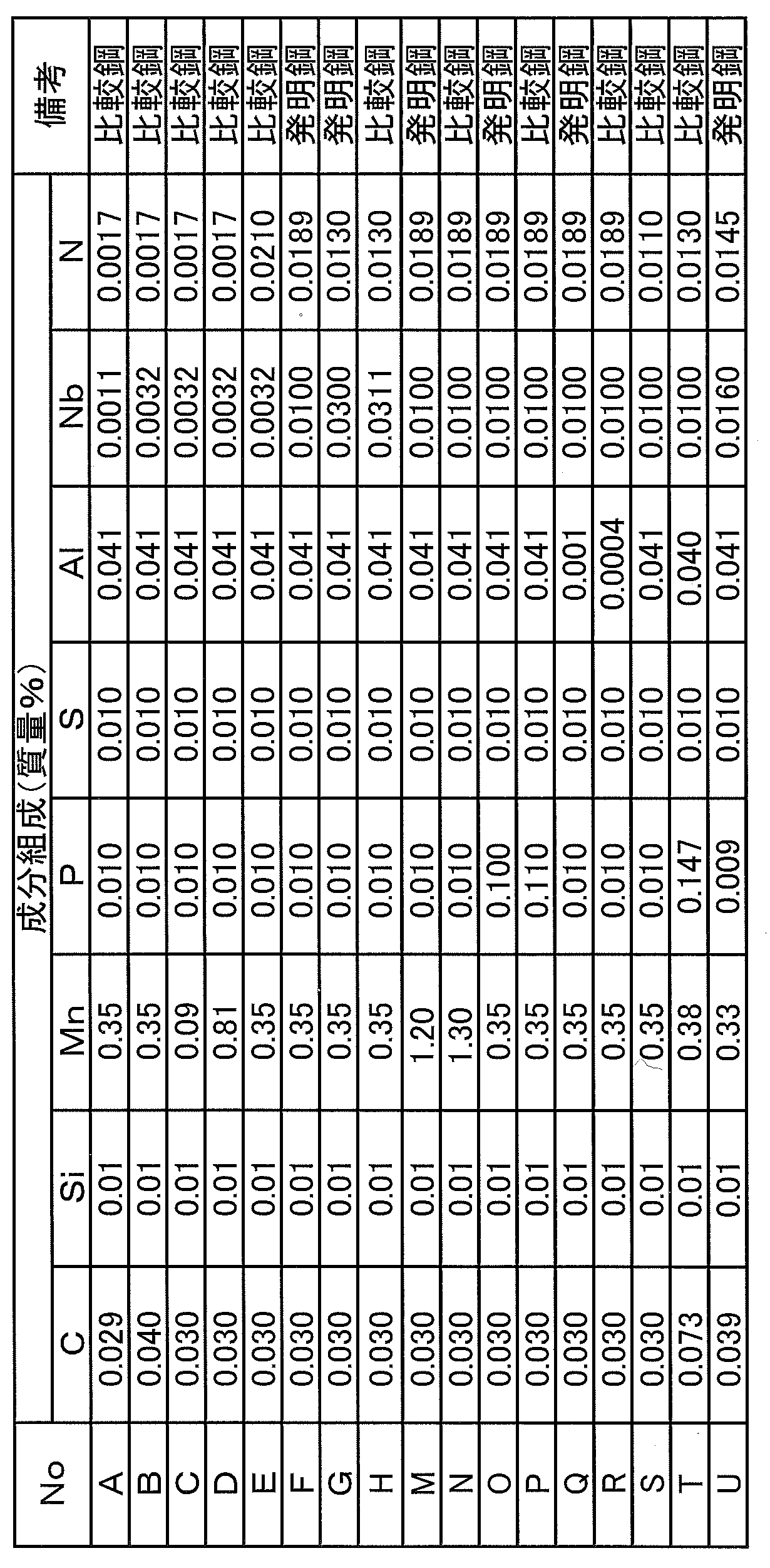
- Component composition is mass%, C: 0.020% to 0.130%, Si: 0.04% or less, Mn: 0.10% to 1.20%, P: 0.007 %: 0.100% or less, S: 0.030% or less, Al: 0.001% or more and 0.100% or less, N: 0.0120% to 0.0200% or less, Nb: 0.0060% or more, 0 0.0300% or less, the balance being iron and inevitable impurities, the upper yield strength is 460 to 680 MPa, the total elongation is 12% or more, and the solid solution Nb in the region from the surface to 1/8 depth position The absolute value of the difference between the amount and the amount of solute Nb in the region from the 3/8 depth position to the 4/8 depth position is 0.0010% by mass or more.
- the 1/8 depth position, the 3/8 depth position, and the 4/8 depth position are the 1/8 depth position, 3/8 depth position, 4 / 8 depth position.
- a primary cold rolling step in which primary rolling is performed at a reduction rate of 80% or more
- a soaking temperature 660 to 800 ° C.
- Heating time 55 s or less
- average cooling rate from soaking temperature to cooling stop temperature 250 to 400 ° C .
- annealing process in which annealing is performed at 30 ° C./s or more and less than 150 ° C./s
- reduction ratio after the annealing process And a secondary cold rolling process in which secondary rolling is performed at 1 to 19%.
- % which shows the component of steel is mass% altogether.
- the present invention by increasing the strength of the steel sheet, it is possible to ensure high strength of the can even if the can is made thinner. Further, due to the high ductility, it is possible to perform strong can barrel processing and flange processing such as bead processing and can expansion processing used in welded cans.
- the component composition of the present invention is mass%, C: 0.020% or more and 0.130% or less, Si: 0.04% or less, Mn: 0.10% or more and 1.20% or less, P: 0.007. %: 0.100% or less, S: 0.030% or less, Al: 0.001% or more and 0.100% or less, N: 0.0120% to 0.0200% or less, Nb: 0.0060% or more, 0 0.0300% or less, and the balance consists of iron and inevitable impurities.
- the ductility can be increased without inferior in ductility by changing the ferrite structure by solid solution strengthening with N and a solid solution of solid solution Nb, it is not necessary to contain any other component composition. For example, addition of Ti or B may deteriorate ductility and corrosion resistance, and is not contained in the present invention.
- the steel plate for cans of the present invention it is important to have an upper yield strength of 460 to 680 MPa and a total elongation of 12% or more.
- the C content of the steel plate for cans is important. Specifically, it is necessary to set the lower limit of the C content to 0.020%. On the other hand, if the C content exceeds 0.130%, subperitectic cracking occurs during the cooling process during steel melting. For this reason, the upper limit of the C content is 0.130%.
- the C content exceeds 0.040%, the strength of the hot-rolled sheet increases and the deformation resistance during cold rolling tends to increase, and the rolling speed is reduced to avoid surface defects after rolling. You may need to do that.
- the C content is preferably 0.020% or more and 0.040% or less.
- Si 0.04% or less Si is an element that increases the strength of steel by solid solution strengthening.
- the Si content is preferably 0.01% or more.
- the Si content is set to 0.04% or less.
- Mn 0.10% or more and 1.20% or less Mn increases the strength of steel by solid solution strengthening.
- the Mn content must be 0.10% or more. Therefore, the lower limit of the Mn content is 0.10%.
- the upper limit of the Mn content is 1.20%. Preferably, it is 0.13% or more and 0.60% or less.
- P 0.007% or more and 0.100% or less
- P is an element having a large solid solution strengthening ability. In order to acquire such an effect, 0.007% or more needs to be contained. Moreover, in order to make P content less than 0.007%, dephosphorization time rises significantly. For this reason, the P content is set to 0.007% or more. However, if the P content exceeds 0.100%, the corrosion resistance is poor. For this reason, the P content is 0.100% or less. Preferably, it is 0.008% or more and 0.030% or less.
- the steel plate for cans of the present invention has a high C and N content and contains Nb that forms precipitates that cause slab cracking, the slab edge is cracked in the straightening zone during continuous casting. It becomes easy.
- the S content is 0.030% or less.
- the S content is 0.020% or less. More preferably, the S content is 0.010% or less.
- the S content is preferably 0.005% or more.
- the recrystallization temperature rises. Therefore, it is necessary to set the annealing temperature higher by the increase in the Al content.
- the recrystallization temperature rises due to the influence of other elements contained in order to increase the upper yield strength, and the annealing temperature must be set high. Therefore, it is necessary to avoid the increase in the recrystallization temperature due to Al as much as possible. Therefore, the Al content is 0.100% or less.
- the Al content is set to 0.001% or more.
- Al is preferably added as a deoxidizer, and in order to obtain this effect, the Al content is preferably 0.010% or more.
- N 0.0120% to 0.0200% or less
- N is an element necessary for increasing solid solution strengthening. In order to exert the effect of solid solution strengthening, the N content needs to be over 0.0120%. On the other hand, when there is too much N content, it will become easy to produce a slab crack in the lower correction zone where the temperature at the time of continuous casting falls. Therefore, the N content is 0.0200% or less. Preferably, it is 0.0130% or more and 0.0190% or less.
- Nb 0.0060% or more and 0.0300% or less
- Nb is an element having a high carbide generating ability and precipitates fine carbides.
- the upper yield strength increases.
- the upper yield strength can be adjusted by the Nb content. Since this effect occurs when the Nb content is 0.0060% or more, the lower limit of the Nb content is set to 0.0060%.
- Nb brings about an increase in recrystallization temperature. Therefore, when the Nb content exceeds 0.0300%, a large amount of unrecrystallized structure is caused by annealing at an annealing temperature of 660 to 800 ° C. and a soaking time of 55 s or less. It remains difficult to anneal. For this reason, the upper limit of Nb content is limited to 0.0300%. Preferably, it is 0.0070% or more and 0.0250% or less.
- the remainder other than the above is Fe and inevitable impurities.
- the absolute value of the difference between the solid solution Nb amount in the region from the surface to the 1/8 depth position and the solid solution Nb amount in the region from the 3/8 depth position to the 4/8 depth position is 0.0010 mass. % Or more.
- the 1/8 depth position, 3/8 depth position, and 4/8 depth position are the 1/8 depth position, 3/8 depth position, and 4/8 depth from the surface in the plate thickness direction. Position.
- the upper yield strength can be further increased by increasing the amount of solute Nb in the region from the 3/8 depth position to the 4/8 depth position.
- good total elongation high ductility
- the absolute value of the difference in the amount of solute Nb in the thickness direction is 0.0010% by mass or more, the high ductility (total elongation is 12% or more) and the high strength (upper yield strength) are intended. 460-680 MPa).
- the absolute value of the difference in the amount of solute Nb is set to 0.0010% by mass or more. Preferably it is 0.0023 mass% or more.
- the absolute value of the difference in the amount of solute Nb exceeds 0.0050% by mass, it is difficult to achieve both the total elongation and the upper yield point, so 0.0050% by mass or less is preferable.
- the difference in the amount of solute Nb is reduced if the average cooling rate after soaking is lowered in the annealing process, and the difference is increased if the average cooling rate is increased.
- the amount of solute Nb in the region from the surface to the 1/8 depth position is preferably 0.0014 to 0.0105% by mass.
- the amount of solute Nb in the region from the 3/8 depth position to the 4/8 depth position is preferably 0.0017 to 0.0095 mass%.
- the amount of solute Nb in the region from the surface to the 1/8 depth position is constant current electrolysis in a 10% acetylacetone-1% tetramethylammonium chloride-methanol solution up to a depth of 1/8 of the plate thickness (20 mA / cm 2 ), and Nb in the electrolyte can be measured by inductively coupled plasma emission spectroscopy.
- the amount of the solid solution Nb in the region from the 3/8 depth position to the 4/8 depth position is chemically polished with a 20 wt% oxalic acid aqueous solution until the depth becomes 3/8 depth of the plate thickness, and then the sample is 4 mm thick.
- the upper yield strength is set to 460 MPa or more.
- the upper yield strength is 680 MPa or less.
- the upper yield strength of the steel plate for cans can be controlled to 460 to 680 MPa by employing the above component composition and, for example, the production conditions described later.
- Total elongation 12% or more If the total elongation of the steel sheet for cans is less than 12%, for example, cracks and other defects occur in the manufacture of cans formed by can body processing such as bead processing and can expansion processing. There is a risk. On the other hand, if the total elongation is less than 12%, cracks may occur during flange processing of the can. Therefore, the lower limit of total elongation is 12%.
- the total elongation can be controlled to 12% or more by adjusting the cooling rate after soaking of the annealing and setting the rolling reduction in the secondary cold rolling process after the annealing process to a specific range. On the other hand, in order to obtain a total elongation exceeding 30%, an excessive cost is required for controlling the components and production conditions, so 30% or less is preferable.
- Plate thickness is 0.4mm or less (preferred condition)
- steel sheets are being made thinner in order to reduce can manufacturing costs.
- the strength of the can may be reduced as the thickness of the steel plate is reduced, that is, as the thickness of the steel plate is reduced.
- the steel plate for cans of the present invention does not reduce the strength of the can even when the plate thickness is thin.
- the plate thickness is preferably 0.4 mm or less. It may be 0.3 mm or less, and may be 0.2 mm or less.
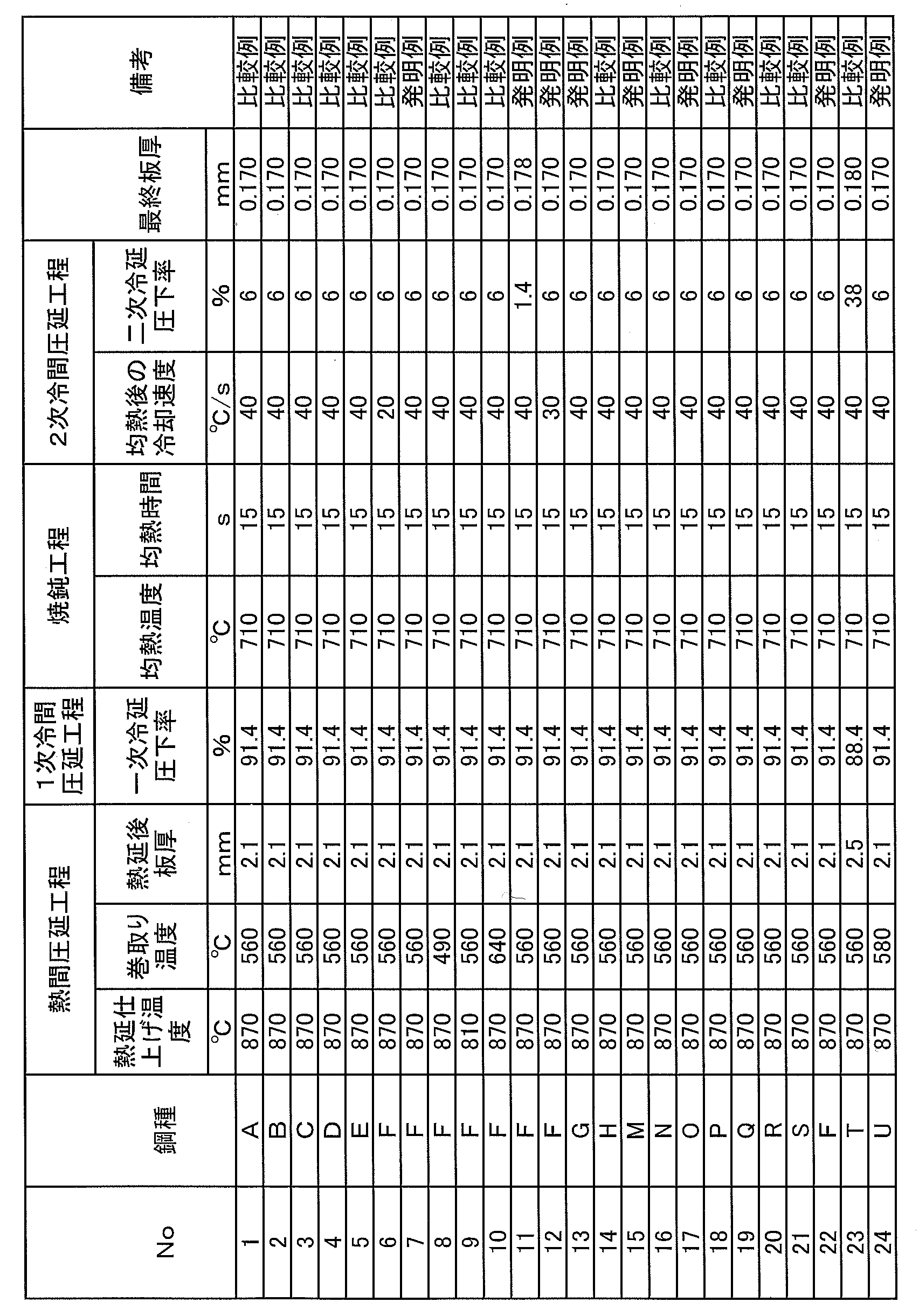
- the method for producing a steel plate for a can according to the present invention comprises a hot rolling step in which a steel slab having the above composition is rolled at a finish rolling temperature of 820 ° C. or more and wound at a winding temperature of 500 to 620 ° C.
- Steel is obtained by melting molten steel adjusted to the above-described component composition by a known melting method using a converter or the like, and then forming a rolled material by a commonly used casting method such as a continuous casting method. It is done.
- the steel obtained as described above is rolled at a finish rolling temperature of 820 ° C. or higher and hot rolled at a winding temperature of 500 to 620 ° C. to produce a hot rolled steel sheet.
- the temperature of the steel is preferably 1200 ° C. or higher.
- Finish rolling temperature 820 ° C. or higher
- the finish rolling temperature in hot rolling is an important factor in securing the upper yield strength.
- the finish rolling temperature in the hot rolling is set to 820 ° C. or higher.
- the upper limit is not particularly limited, but it is preferable to set the upper limit to 980 ° C. for the purpose of suppressing scale generation.
- Winding temperature 500-620 ° C
- the coiling temperature is an important requirement for controlling the upper yield strength and the total elongation, which are important requirements in the present invention.
- the minimum of coiling temperature shall be 500 degreeC.
- the coiling temperature exceeds 620 ° C.
- N added for solid solution strengthening becomes AlN and precipitates in the central layer, so that the amount of solid solution N decreases, and as a result, the upper yield strength decreases. .
- the upper limit of coiling temperature shall be 620 degreeC.
- it is 520 to 600 ° C.
- pickling is performed, and primary cold rolling is performed in which rolling is performed at a rolling reduction of 80% or more.
- the pickling method is not particularly limited. What is necessary is just to be able to remove the surface layer scale of the steel sheet, and pickling can be performed by a usual method. Moreover, you may remove a scale by methods other than pickling.
- Reduction ratio in cold rolling 80% or more
- the reduction ratio in primary cold rolling is one of the important requirements in the present invention. If the reduction ratio in the primary cold rolling is less than 80%, it is difficult to produce a steel plate having an upper yield strength of 460 MPa or more. Furthermore, when the reduction rate in this step is less than 80%, in order to obtain a plate thickness (about 0.17 mm) comparable to that of a conventional DR material in which the reduction rate of secondary cold rolling is 20% or more, At least the thickness of the hot-rolled sheet needs to be 0.9 mm or less. However, in operation, it is difficult to set the thickness of the hot rolled sheet to 0.9 mm or less. Therefore, the rolling reduction in this step is 80% or more. In addition, another process may be appropriately included after the hot rolling process and before the primary cold rolling process. Moreover, you may perform a primary cold rolling process, without performing pickling immediately after a hot rolling process.
- annealing is performed under conditions of soaking temperature: 660 to 800 ° C., holding time: 55 s or less, average cooling rate from soaking temperature to cooling stop temperature: 250 to 400 ° C .: 30 ° C./s or more and less than 150 ° C./s. Do.
- Soaking temperature 660-800 ° C
- the soaking temperature is set to 660 ° C. or higher.
- the soaking temperature is 660 to 800 ° C.
- it is 660 to 760 ° C.
- Soaking time 55 s or less Productivity cannot be secured at a speed at which the soaking time exceeds 55 s. Therefore, the soaking time is 55 s or less.
- the lower limit of the soaking time is not particularly limited, but in order to shorten the soaking time, it is necessary to increase the conveying speed. If the conveying speed is increased, it becomes difficult to stably convey without meandering. For the above reasons, it is preferable to set 10s as the lower limit.
- the average cooling rate from the soaking temperature to the cooling stop temperature 250 to 400 ° C .: 30 ° C./s or more and less than 150 ° C./s
- rapid cooling treatment is performed.
- the cooling rate increases, a solid solution Nb distribution occurs in the thickness direction. This is thought to be because the cooling rate is high, resulting in nonuniform cooling in the plate thickness direction. It is considered that the concentration distribution is generated by influencing the diffusion movement of Nb by being cooled unevenly. Since solute Nb suppresses ferrite grain growth by a solution drag effect, it affects the ferrite grain size in a fine region of the extreme surface layer.
- the cooling rate is less than 30 ° C./s, since the cooling rate is low, the cooling is uniformly performed in the thickness direction, and no solid solution Nb distribution occurs in the thickness direction. As a result, it becomes difficult to achieve both high strength characteristics and high ductility characteristics. Therefore, it shall be 30 degrees C / s or more. Preferably, it is 35 ° C./s or more. More preferably, it is 40 ° C./s or more.
- the cooling rate becomes too high and it becomes impossible to cool uniformly in the width direction, so that the solid solution Nb varies and becomes a non-uniform material. Therefore, it is set to less than 150 ° C./s. Preferably, it is 130 degrees C / s or less. More preferably, it is 120 ° C./s or less.
- the cooling stop temperature is set to 250 to 400 ° C. from the viewpoint of obtaining a uniform temperature without variation in the width direction and the target strength. If it is less than 250 ° C., it is difficult to obtain a uniform temperature without variation in the width direction, and the upper yield strength varies in the width direction.
- the temperature exceeds 400 ° C., the amount of precipitated C increases due to the overaging treatment, and the upper yield strength decreases.
- a continuous annealing apparatus is used for annealing.
- another process may be appropriately included before the annealing process after the primary cold rolling process, or the annealing process may be performed immediately after the primary cold rolling process.
- secondary cold rolling is performed in which secondary rolling is performed at a reduction ratio of 1 to 19%.
- the reduction ratio in the secondary cold rolling is set to 19% or less.
- secondary cold rolling has a role of imparting surface roughness of the steel sheet, and in order to uniformly impart surface roughness to the steel sheet, the reduction ratio of secondary cold rolling needs to be 1% or more. Preferably, it is 8 to 19%.
- another process may be appropriately included before the secondary cold rolling process after the annealing process, or the secondary cold rolling process may be performed immediately after the annealing process.
- the steel plate for cans of the present invention can be obtained.
- various processes can be further performed after the secondary cold rolling.
- the plating layer include an Sn plating layer, a Cr plating layer such as tin-free, an Ni plating layer, and an Sn—Ni plating layer.
- the Sn-plated steel sheet obtained above was subjected to a heat treatment corresponding to a coating baking process at 210 ° C. for 10 minutes and then subjected to a tensile test to measure the upper yield strength and the total elongation.
- the pressure strength, formability, and corrosion resistance were investigated. Further, the amount of dissolved Nb was measured.
- the measurement method and survey method are as follows.
- the amount of solid solution Nb in the region from the 3/8 depth position to the 4/8 depth position was chemically polished with a 20 wt% oxalic acid aqueous solution until reaching a depth of 3/8 of the plate thickness.
- Tensile test JIS No. 5 tensile test piece (JIS Z 2201) with the direction parallel to the rolling direction as the tensile direction is collected, subjected to paint baking equivalent treatment at 210 ° C for 10 minutes, and then stipulated in JIS Z 2241 A compliant tensile test was performed at a tensile speed of 10 mm / min, and an upper yield point (U-YP) and total elongation (El) were measured.
- Roll forming is performed so that the winding width is 5 mm with the pressure-resistant strength rolling direction as the bending direction, both ends of the cylindrical shape are seam welded by electric resistance welding, neck forming and flange forming are performed, and then the lid is wound to empty A can sample was made.
- the obtained empty can sample was put into a chamber, pressurized with compressed air, and the pressure at which the sample buckled after pressurization was measured.
- the buckling pressure was 0.20 MPa or more, it was evaluated as acceptable ( ⁇ ), less than 0.20 MPa as 0.13 MPa or more as acceptable ( ⁇ ), and less than 0.13 MPa as unacceptable (x).
- Roll forming was performed with the rolling direction as the bending direction and the winding width was 5 mm, both ends of the cylindrical shape were seam welded by electric resistance welding, neck forming was performed, and wrinkles during neck forming were visually observed.
- the case where there was no wrinkle was judged as pass ( ⁇ ), the case where one fine wrinkle was seen visually was accepted ( ⁇ ), and the case where two or more fine wrinkles were seen visually was judged as unacceptable (x).
- the sample after corrosion-resistant annealing was subjected to Sn plating with an adhesion amount of 11.2 g / m 2 on one side, and the number of sites where the Sn plating was thinned and observed as holes was measured. Observation was carried out at a measurement area of 2.7 mm 2 with an optical microscope of 50 times. The case where the number was 20 or less was marked as ⁇ , and the case where the number was 21 or more was marked as x. The results obtained as described above are shown in Table 3.
- the present invention it is possible to obtain a steel plate for cans having high strength, excellent ductility, and good corrosion resistance even for highly corrosive contents.
- the present invention is most suitable as a steel plate for cans centering on a three-piece can with a high degree of can body processing and a two-piece can whose bottom portion is processed by several percent.
Landscapes
- Chemical & Material Sciences (AREA)
- Engineering & Computer Science (AREA)
- Mechanical Engineering (AREA)
- Materials Engineering (AREA)
- Metallurgy (AREA)
- Organic Chemistry (AREA)
- Crystallography & Structural Chemistry (AREA)
- Physics & Mathematics (AREA)
- Thermal Sciences (AREA)
- Heat Treatment Of Sheet Steel (AREA)
Abstract
Description
[1]成分組成は、質量%で、C:0.020%以上0.130%以下、Si:0.04%以下、Mn:0.10%以上1.20%以下、P:0.007%以上0.100%以下、S:0.030%以下、Al:0.001%以上0.100%以下、N:0.0120%超え0.0200%以下、Nb:0.0060%以上0.0300%以下を含有し、残部が鉄および不可避的不純物からなり、上降伏強度が460~680MPa、全伸びが12%以上であり、表面から1/8深さ位置までの領域における固溶Nb量と、3/8深さ位置から4/8深さ位置までの領域における固溶Nb量の差の絶対値が、0.0010質量%以上であることを特徴とする缶用鋼板。
なお、前記1/8深さ位置、前記3/8深さ位置、前記4/8深さ位置とは、表面から板厚方向に1/8深さ位置、3/8深さ位置、4/8深さ位置である。
[2]上記[1]に記載の缶用鋼板の製造方法であって、鋼スラブを、仕上げ圧延温度:820℃以上で圧延し、巻取温度:500~620℃で巻取る熱間圧延工程と、前記熱間圧延後、酸洗し、圧下率:80%以上で1次圧延する1次冷間圧延工程と、前記1次冷間圧延工程後、均熱温度:660~800℃、均熱時間:55s以下、均熱温度から冷却停止温度:250~400℃までの平均冷却速度:30℃/s以上150℃/s未満で焼鈍を行う焼鈍工程と、前記焼鈍工程後、圧下率:1~19%で2次圧延を行う2次冷間圧延工程とを有することを特徴とする缶用鋼板の製造方法。
なお、本明細書において、鋼の成分を示す%は、すべて質量%である。
本発明の缶用鋼板においては、460~680MPaの上降伏強度と12%以上の全伸びを有することが重要である。そのためには、Nbを含有することで生成するNbCによる析出強化を利用することが重要となる。NbCによる析出強化を利用するためには、缶用鋼板のC含有量が重要となる。具体的には、C含有量の下限を0.020%とすることが必要である。一方、C含有量が0.130%を超えると、鋼の溶製中冷却過程の中で亜包晶割れを起こす。このため、C含有量の上限は0.130%とする。なお、C含有量が0.040%を超えると熱延板の強度が上昇し、冷間圧延時の変形抵抗が増加する傾向にあり、圧延後の表面欠陥を回避するために圧延速度を小さくする必要が発生する場合がある。このため、製造しやすさの観点からは、C含有量は0.020%以上0.040%以下とすることが好ましい。
Siは固溶強化により鋼を高強度化させる元素である。この効果を得るためには、Si含有量は0.01%以上とすることが好ましい。しかし、Si含有量が0.04%を超えると耐食性が著しく損なわれる。よって、Si含有量は0.04%以下とする。
Mnは固溶強化により鋼の強度を増加させる。目標の上降伏強度を確保するにはMn含有量を0.10%以上にする必要がある。よって、Mn含有量の下限を0.10%とする。一方、Mn含有量が1.20%を超えると耐食性、表面特性が劣る。よって、Mn含有量の上限を1.20%とする。好ましくは、0.13%以上0.60%以下である。
Pは固溶強化能が大きい元素である。このような効果を得るためには0.007%以上の含有が必要である。また、P含有量を0.007%未満とするには脱りん時間が大幅に上昇する。このため、P含有量は0.007%以上とする。しかし、Pの含有量が0.100%を超えると耐食性が劣る。このため、P含有量は0.100%以下とする。好ましくは、0.008%以上0.030%以下である。
本発明の缶用鋼板はC、N含有量が高く、また、スラブ割れの原因となる析出物を形成するNbを含むため、連続鋳造時矯正帯でスラブエッジが割れやすくなる。スラブ割れを防止する点からS含有量は0.030%以下にする。好ましくは、S含有量は0.020%以下である。より好ましくは、S含有量は0.010%以下である。一方、Sを0.005%未満とすると脱Sコストが過大となるため、S含有量は0.005%以上とすることが好ましい。
Al含有量が増加すると、再結晶温度の上昇がもたらされるため、Al含有量の増加分だけ焼鈍温度を高く設定する必要がある。本発明においては、上降伏強度を増加させるために含有する他の元素の影響で再結晶温度が上昇し、焼鈍温度を高く設定しなければならない。そこで、Alによる再結晶温度の上昇を極力回避することが必要である。よって、Al含有量は0.100%以下とする。一方、固溶Nを完全に除去するのは困難なため、Al含有量を0.001%以上とする。なお、Alは脱酸剤として添加することが好ましく、この効果を得るためにはAl含有量を0.010%以上とすることが好ましい。
Nは固溶強化を増加させるために必要な元素である。固溶強化の効果を発揮させるためには、N含有量を0.0120%超えとする必要がある。一方、N含有量が多すぎると、連続鋳造時の温度が低下する下部矯正帯でスラブ割れが生じやすくなる。よって、N含有量は0.0200%以下とする。好ましくは、0.0130%以上0.0190%以下である。
Nbは炭化物生成能の高い元素であり、微細な炭化物を析出させる。これにより、上降伏強度が上昇する。本発明では、Nb含有量によって上降伏強度を調整することができる。Nb含有量が0.0060%以上でこの効果が生じるため、Nb含有量の下限は0.0060%とする。一方、Nbは再結晶温度の上昇をもたらすので、Nb含有量が0.0300%を超えると、660~800℃の焼鈍温度、55s以下の均熱時間での焼鈍では未再結晶組織が多量に残存するなど、焼鈍し難くなる。このため、Nb含有量の上限は0.0300%に限定する。好ましくは、0.0070%以上0.0250%以下である。
なお、1/8深さ位置、3/8深さ位置、4/8深さ位置とは、表面から板厚方向に1/8深さ位置、3/8深さ位置、4/8深さ位置である。
3/8深さ位置から4/8深さ位置までの領域における固溶Nb量を増やすことで上降伏強度をより上昇させることができる。一方、表面から1/8深さ位置までの領域では固溶Nb量を変化させることで良好な全伸び(高延性)を得ることができる。そこで、板厚方向で固溶Nb量に差をつけることで、延性と強度を極めて優れた状態で両立させることができると考えた。この板厚方向での固溶Nb量の差の絶対値が0.0010質量%以上であれば、本発明の目的とする高延性(全伸びが12%以上)と高強度(上降伏強度が460~680MPa)が得られる。以上より、固溶Nb量の差の絶対値を0.0010質量%以上とする。好ましくは0.0023質量%以上である。一方、固溶Nb量の差の絶対値が0.0050質量%を超えると全伸びと上降伏点の両立が困難となるため、0.0050質量%以下が好ましい。
3/8深さ位置から4/8深さ位置までの領域における固溶Nb量を0.0017~0.0095質量%とすることで、上降伏強度、全伸びが優れた値となる。
溶接缶のデント強度、2ピース缶の耐圧強度等を確保するために、上降伏強度を460MPa以上とする。一方、680MPa超えの上降伏強度を得ようとすると多量の元素含有が必要となる。多量の元素含有は本発明の缶用鋼板の耐食性を阻害するおそれがある。そこで、上降伏強度は680MPa以下とする。上記成分組成を採用するとともに、例えば後述する製造条件を採用することで、缶用鋼板の上降伏強度を460~680MPaに制御することができる。
缶用鋼板の全伸びが12%を下回ると、例えば、ビード加工や拡缶加工のような缶胴加工により成形される缶の製造においてクラックなどの割れ発生の不具合が発生するおそれがある。また、全伸びが12%を下回ると、缶のフランジ加工時にクラックが発生するおそれがある。従って、全伸びの下限は12%とする。例えば、焼鈍の均熱後の冷却速度を調整し、焼鈍工程後の2次冷間圧延工程の圧下率を特定の範囲にすることにより全伸び12%以上に制御することができる。一方、30%を超える全伸びを得るためには成分および製造条件の制御に過大なコストが必要となるため、30%以下が好ましい。
現在、製缶コストの低減を目的として、鋼板の薄肉化が進められている。しかしながら、鋼板の薄肉化、すなわち、鋼板板厚の低減に伴って、缶体強度の低下が懸念される。これに対して、本発明の缶用鋼板は、板厚が薄い場合でも、缶体強度を低下させることがない。板厚が薄い場合に、高延性かつ高強度という本発明の効果が顕著にでる。この点から、板厚は0.4mm以下とすることが好ましい。0.3mm以下としてよく、0.2mm以下としてよい。
本発明の缶用鋼板の製造方法は、上記成分組成からなる鋼スラブを、仕上げ圧延温度:820℃以上で圧延し、巻取温度:500~620℃で巻取る熱間圧延工程と、前記熱間圧延後、酸洗し、圧下率:80%以上で1次圧延する1次冷間圧延工程と、1次冷間圧延工程後、均熱温度:660~800℃、保持時間:55s以下、均熱温度から冷却停止温度:250~400℃までの平均冷却速度:30℃/s以上150℃/s未満の条件で焼鈍を行う焼鈍工程と、前記焼鈍工程後、圧下率:1~19%で2次圧延を行う2次冷間圧延工程とを有する。
熱間圧延における仕上げ圧延温度は、上降伏強度を確保する上で重要因子となる。仕上げ温度が820℃未満では、オーステナイト+フェライト(γ+α)の2相域熱延により粒成長し、冷間圧延し焼鈍した後の結晶粒が粗大化する。その結果、上降伏強度が低下する。よって、熱間圧延における仕上げ圧延温度は820℃以上とする。この上限は特に限定されないが、スケール発生を抑制するという理由で980℃を上限とすることが好ましい。
巻取温度は、本発明で重要な要件である上降伏強度および全伸びを制御する上で重要な要件である。巻取温度を500℃未満にすると、表層が早く冷却されるため、表層のAlN量が少なくなり、表層の固溶N量が増加する。このため、巻取温度の下限は500℃とする。一方、巻取温度が620℃を超えると、固溶強化のために添加したNがAlNとなって中央層に析出して、固溶N量が低下し、その結果、上降伏強度が低下する。このため、巻取温度の上限を620℃とする。好ましくは、520~600℃である。
1次冷間圧延における圧下率は、本発明において重要な要件の一つである。1次冷間圧延での圧下率が80%未満では、上降伏強度が460MPa以上の鋼板を製造することは困難である。さらに、本工程での圧下率を80%未満とした場合、2次冷間圧延の圧下率を20%以上とした従来のDR材並みの板厚(0.17mm程度)を得るためには、少なくとも熱延板の板厚を0.9mm以下にまでする必要がある。しかし、操業上、熱延板の板厚を0.9mm以下とすることは困難である。従って、本工程での圧下率は80%以上とする。
なお、熱間圧延工程後1次冷間圧延工程前に適宜他の工程が含まれても良い。また、熱間圧延工程の直後に酸洗を行わずに1次冷間圧延工程を行っても良い。
鋼板の組織をより均一にするためには、均熱温度を660℃以上にする。一方、均熱温度が800℃超えの条件で焼鈍するためには、鋼板の破断を防止するために極力搬送速度を落とす必要があり、生産性が低下する。以上から、均熱温度は660~800℃とする。好ましくは、660~760℃である。
均熱時間が55s超えになるような速度では、生産性を確保できない。よって、均熱時間は55s以下とする。均熱時間の下限は特に限定されないが、均熱時間を短くするためには、搬送速度を速くすることが必要となる。搬送速度を速くすると蛇行させずに安定的に搬送することが難しくなる。以上の理由から、10sを下限とすることが好ましい。
均熱後に急冷処理を行う。冷却速度が大きくなると板厚方向に固溶Nb分布が生じる。これは、冷却速度が大きいために板厚方向で不均一に冷却されるためと考えられる。不均一に冷却されることで、Nbの拡散移動に影響を及ぼし、濃度分布が生じると考えられる。固溶Nbは、フェライト粒成長をソリュートドラッグ効果で抑制するため、極表層の微細な領域でフェライト粒径に影響を及ぼす。さらに、本発明では、板厚方向に固溶Nb分布が生じることにより、表層と中央層で微細な材質差が生じる。その結果、高延性と高強度を両立することが可能となる。冷却速度が30℃/s未満の場合は、冷却速度が低いために板厚方向で均一に冷却され板厚方向に固溶Nb分布は生じない。その結果、高強度特性と高延性特性の両立が難しくなる。そのため、30℃/s以上とする。好ましくは、35℃/s以上である。さらに好ましくは、40℃/s以上である。一方、150℃/s以上だと冷却速度が大きくなりすぎ、幅方向に均一に冷却することが出来なくなるため、固溶Nbがばらつき不均一な材料となる。そのため、150℃/s未満とする。好ましくは、130℃/s以下である。さらに好ましくは、120℃/s以下である。
冷却停止温度は幅方向にばらつきなく均一な温度を得ることと、目標強度の点から250~400℃とする。250℃未満では幅方向にばらつきなく均一な温度を得ることが困難になり上降伏強度が幅方向にばらつくためである。400℃超えでは、過時効処理により析出C量が増加して上降伏強度が低下するためである。
なお、焼鈍には連続焼鈍装置を用いる。また、1次冷間圧延工程後焼鈍工程前に適宜他の工程が含まれても良いし、1次冷間圧延工程の直後に焼鈍工程を行っても良い。
焼鈍後の2次冷間圧延での圧下率を通常行われるDR材製造条件と同様(20%以上)にすると、加工時に導入される歪が多くなるため全伸びが低下する。本発明では極薄材で全伸び12%以上を確保する必要があるため、2次冷間圧延での圧下率は19%以下とする。また、2次冷間圧延には鋼板の表面粗さ付与の役割があり、均一に鋼板に表面粗さを付与するために2次冷間圧延の圧下率は1%以上にする必要がある。好ましくは、8~19%である。
なお、焼鈍工程後2次冷間圧延工程前に適宜他の工程が含まれても良いし、焼鈍工程の直後に2次冷間圧延工程を行っても良い。
板厚の1/8の深さまで、試料を10%アセチルアセトン-1%塩化テトラメチルアンモニウム-メタノール溶液中で定電流電解(20 mA/cm2)し、電解液中のNbを誘導結合プラズマ発光分光法で分析し求めた。
圧延方向に対して平行方向を引張方向とするJIS 5号引張試験片(JIS Z 2201)を採取し、210℃で10分間の塗装焼付相当処理を施した後、JIS Z 2241の規定に準拠した引張試験を引張速度10mm/分で行って、上降伏強度(U-YP:upper yield point)、全伸び(El:elongation)を測定した。
圧延方向を曲げ方向として巻幅が5mmになるようにロールフォーム加工し、円筒状の両端を電気抵抗溶接でシーム溶接し、ネック成形、フランジ成形を行い、次いで、蓋を巻き締めて空缶サンプルを作成した。得られた空缶サンプルを、チャンバーに入れ、圧縮空気で加圧し、加圧後にサンプルが座屈した圧力を測定した。座屈時の圧力が0.20MPa以上を合格(◎)、0.20MPa未満0.13MPa以上を合格(○)、0.13MPa未満を不合格(×)とした。
圧延方向を曲げ方向として巻幅が5mmになるようにロールフォーム加工、円筒状の両端を電気抵抗溶接でシーム溶接し、ネック成形を行い、ネック成形時のシワを目視にて観察した。全くシワが無い場合を合格(◎)、目視で微細なシワが1箇所見られる場合を合格(○)、目視で微細なシワが2箇所以上見られる場合を不合格(×)とした。
焼鈍後のサンプルに片面付着量11.2g/m2のSnめっきを施し、Snめっきが薄くなって穴状に観察される部位の個数を計測した。光学顕微鏡50 倍において測定面積2.7mm2で観察を行った。個数が20個以下の場合を○、21個以上の場合を×とした。
以上により得られた結果を表3に示す。

Claims (2)
- 成分組成は、質量%で、C:0.020%以上0.130%以下、
Si:0.04%以下、
Mn:0.10%以上1.20%以下、
P:0.007%以上0.100%以下、
S:0.030%以下、
Al:0.001%以上0.100%以下、
N:0.0120%超え0.0200%以下、
Nb:0.0060%以上0.0300%以下を含有し、残部が鉄および不可避的不純物からなり、
上降伏強度が460~680MPa、全伸びが12%以上であり、
表面から1/8深さ位置までの領域における固溶Nb量と、3/8深さ位置から4/8深さ位置までの領域における固溶Nb量の差の絶対値が、0.0010質量%以上であることを特徴とする缶用鋼板。
なお、前記1/8深さ位置、前記3/8深さ位置、前記4/8深さ位置とは、表面から板厚方向に1/8深さ位置、3/8深さ位置、4/8深さ位置である。 - 請求項1に記載の缶用鋼板の製造方法であって、鋼スラブを、仕上げ圧延温度:820℃以上で圧延し、巻取温度:500~620℃で巻取る熱間圧延工程と、
前記熱間圧延後、酸洗し、圧下率:80%以上で1次圧延する1次冷間圧延工程と、
前記1次冷間圧延工程後、均熱温度:660~800℃、均熱時間:55s以下、均熱温度から冷却停止温度:250~400℃までの平均冷却速度:30℃/s以上150℃/s未満で焼鈍を行う焼鈍工程と、
前記焼鈍工程後、圧下率:1~19%で2次圧延を行う2次冷間圧延工程と
を有することを特徴とする缶用鋼板の製造方法。
Priority Applications (12)
| Application Number | Priority Date | Filing Date | Title |
|---|---|---|---|
| CN201780013649.9A CN108779526A (zh) | 2016-02-29 | 2017-02-02 | 罐用钢板及其制造方法 |
| NZ744555A NZ744555A (en) | 2016-02-29 | 2017-02-02 | Steel sheet for can and method for manufacturing the same |
| BR112018017156-5A BR112018017156A2 (ja) | 2016-02-29 | 2017-02-02 | A steel-for-can board and a manufacturing method for the same |
| MX2018010365A MX375238B (es) | 2016-02-29 | 2017-02-02 | Lamina de acero para lata y metodo para la fabricacion de la misma |
| ES17759537T ES2866892T3 (es) | 2016-02-29 | 2017-02-02 | Chapa de acero para lata y método para fabricar la misma |
| CA3012447A CA3012447C (en) | 2016-02-29 | 2017-02-02 | Steel sheet for can and method for manufacturing the same |
| EP17759537.8A EP3399065B1 (en) | 2016-02-29 | 2017-02-02 | Steel sheet for can and method for manufacturing the same |
| US16/080,067 US10941456B2 (en) | 2016-02-29 | 2017-02-02 | Steel sheet for can and method for manufacturing the same |
| JP2017529095A JP6191807B1 (ja) | 2016-02-29 | 2017-02-02 | 缶用鋼板およびその製造方法 |
| KR1020187024581A KR102096389B1 (ko) | 2016-02-29 | 2017-02-02 | 캔용 강판 및 그의 제조 방법 |
| AU2017227455A AU2017227455B2 (en) | 2016-02-29 | 2017-02-02 | Steel Sheet for Can and Method for Manufacturing the Same |
| PH12018550122A PH12018550122A1 (en) | 2016-02-29 | 2018-07-27 | Steel sheet for can and method for manufacturing the same |
Applications Claiming Priority (2)
| Application Number | Priority Date | Filing Date | Title |
|---|---|---|---|
| JP2016038201 | 2016-02-29 | ||
| JP2016-038201 | 2016-02-29 |
Publications (1)
| Publication Number | Publication Date |
|---|---|
| WO2017150066A1 true WO2017150066A1 (ja) | 2017-09-08 |
Family
ID=59743770
Family Applications (1)
| Application Number | Title | Priority Date | Filing Date |
|---|---|---|---|
| PCT/JP2017/003748 Ceased WO2017150066A1 (ja) | 2016-02-29 | 2017-02-02 | 缶用鋼板およびその製造方法 |
Country Status (15)
| Country | Link |
|---|---|
| US (1) | US10941456B2 (ja) |
| EP (1) | EP3399065B1 (ja) |
| JP (1) | JP6191807B1 (ja) |
| KR (1) | KR102096389B1 (ja) |
| CN (1) | CN108779526A (ja) |
| AU (1) | AU2017227455B2 (ja) |
| BR (1) | BR112018017156A2 (ja) |
| CA (1) | CA3012447C (ja) |
| ES (1) | ES2866892T3 (ja) |
| MX (1) | MX375238B (ja) |
| MY (1) | MY178386A (ja) |
| NZ (1) | NZ744555A (ja) |
| PH (1) | PH12018550122A1 (ja) |
| TW (1) | TWI620824B (ja) |
| WO (1) | WO2017150066A1 (ja) |
Cited By (1)
| Publication number | Priority date | Publication date | Assignee | Title |
|---|---|---|---|---|
| WO2021009966A1 (ja) * | 2019-07-18 | 2021-01-21 | Jfeスチール株式会社 | 箱型焼鈍dr鋼板およびその製造方法 |
Families Citing this family (5)
| Publication number | Priority date | Publication date | Assignee | Title |
|---|---|---|---|---|
| US12203155B2 (en) | 2018-11-21 | 2025-01-21 | Jfe Steel Corporation | Steel sheet for cans and method for manufacturing the same |
| CA3234916A1 (en) * | 2021-10-14 | 2023-04-20 | Tata Steel Ijmuiden B.V. | Method for producing high-strength tinplate and tinplate produced therewith |
| KR20230094461A (ko) * | 2021-12-21 | 2023-06-28 | 주식회사 포스코 | 강도와 연신율이 우수한 냉연강판 및 그 제조방법 |
| KR20240097321A (ko) | 2022-12-20 | 2024-06-27 | 주식회사 포스코 | 캔용 Ni 도금강판 및 그 제조방법 |
| KR20240097187A (ko) | 2022-12-20 | 2024-06-27 | 주식회사 포스코 | 도금강판 및 그 제조방법 |
Citations (9)
| Publication number | Priority date | Publication date | Assignee | Title |
|---|---|---|---|---|
| JPH08325670A (ja) * | 1995-03-29 | 1996-12-10 | Kawasaki Steel Corp | 製缶時の深絞り性及びフランジ加工性と、製缶後の表面性状とに優れ、十分な缶強度を有する製缶用鋼板及びその製造方法 |
| JP2001107187A (ja) * | 1999-08-04 | 2001-04-17 | Kawasaki Steel Corp | 高強度缶用鋼板およびその製造方法 |
| WO2005103316A1 (ja) * | 2004-04-27 | 2005-11-03 | Jfe Steel Corporation | 缶用鋼板およびその製造方法 |
| JP2005350737A (ja) * | 2004-06-11 | 2005-12-22 | Nippon Steel Corp | 強い缶体強度と良好なプレス加工性を備えた缶用薄鋼板およびその製造方法 |
| JP2008138234A (ja) * | 2006-11-30 | 2008-06-19 | Jfe Steel Kk | 高強度高延性缶用鋼板およびその製造方法 |
| WO2008105524A1 (ja) * | 2007-02-28 | 2008-09-04 | Jfe Steel Corporation | 缶用鋼板およびその母材に用いる熱延鋼板ならびにそれらの製造方法 |
| JP2009007607A (ja) * | 2007-06-27 | 2009-01-15 | Nippon Steel Corp | 極薄容器用鋼板 |
| WO2009123356A1 (ja) * | 2008-04-03 | 2009-10-08 | Jfeスチール株式会社 | 高強度缶用鋼板およびその製造方法 |
| JP2013028842A (ja) * | 2011-07-29 | 2013-02-07 | Jfe Steel Corp | 高強度高加工性缶用鋼板およびその製造方法 |
Family Cites Families (13)
| Publication number | Priority date | Publication date | Assignee | Title |
|---|---|---|---|---|
| JP3369657B2 (ja) | 1993-08-26 | 2003-01-20 | 川崎製鉄株式会社 | 焼付け硬化性、耐時効性およびノンイヤリング性に優れた高強度高加工性製缶用鋼板およびその製造方法 |
| CN1040777C (zh) | 1995-05-19 | 1998-11-18 | 宝山钢铁(集团)公司 | 大型球罐钢及热处理方法 |
| JPH11315343A (ja) * | 1998-03-06 | 1999-11-16 | Kawasaki Steel Corp | 溶接缶用スリット鋼帯およびその製造方法ならびにスリット鋼帯用冷延鋼帯コイル |
| JP4051778B2 (ja) | 1998-10-08 | 2008-02-27 | Jfeスチール株式会社 | 表面性状が良好な3ピース缶に適した缶用鋼板 |
| JP4810766B2 (ja) | 2001-07-05 | 2011-11-09 | Jfeスチール株式会社 | 軽量2ピース缶用極薄高強度鋼板の製造方法 |
| JP3887009B2 (ja) | 2002-12-05 | 2007-02-28 | 東洋鋼鈑株式会社 | 薄肉化深絞りしごき缶用鋼板およびその製造法 |
| JP5135868B2 (ja) * | 2007-04-26 | 2013-02-06 | Jfeスチール株式会社 | 缶用鋼板およびその製造方法 |
| JP4235247B1 (ja) * | 2007-09-10 | 2009-03-11 | 新日本製鐵株式会社 | 製缶用高強度薄鋼板及びその製造方法 |
| JP5794004B2 (ja) | 2011-07-12 | 2015-10-14 | Jfeスチール株式会社 | フランジ加工性に優れる高強度缶用鋼板およびその製造方法 |
| DE102011056846B4 (de) | 2011-12-22 | 2014-05-28 | Thyssenkrupp Rasselstein Gmbh | Verfahren zur Herstellung eines Aufreißdeckels sowie Verwendung eines mit einer Schutzschicht versehenen Stahlblechs zur Herstellung eines Aufreißdeckels |
| DE102011056847B4 (de) | 2011-12-22 | 2014-04-10 | Thyssenkrupp Rasselstein Gmbh | Stahlblech zur Verwendung als Verpackungsstahl sowie Verfahren zur Herstellung eines Verpackungsstahls |
| CN104334460A (zh) * | 2012-06-06 | 2015-02-04 | 杰富意钢铁株式会社 | 三片罐及其制造方法 |
| JP5655839B2 (ja) | 2012-10-26 | 2015-01-21 | Jfeスチール株式会社 | 缶用鋼板の母材に用いる熱延鋼板およびその製造方法 |
-
2017
- 2017-02-02 WO PCT/JP2017/003748 patent/WO2017150066A1/ja not_active Ceased
- 2017-02-02 BR BR112018017156-5A patent/BR112018017156A2/ja not_active Application Discontinuation
- 2017-02-02 US US16/080,067 patent/US10941456B2/en active Active
- 2017-02-02 JP JP2017529095A patent/JP6191807B1/ja active Active
- 2017-02-02 EP EP17759537.8A patent/EP3399065B1/en active Active
- 2017-02-02 NZ NZ744555A patent/NZ744555A/en not_active IP Right Cessation
- 2017-02-02 KR KR1020187024581A patent/KR102096389B1/ko active Active
- 2017-02-02 MX MX2018010365A patent/MX375238B/es active IP Right Grant
- 2017-02-02 ES ES17759537T patent/ES2866892T3/es active Active
- 2017-02-02 CN CN201780013649.9A patent/CN108779526A/zh active Pending
- 2017-02-02 CA CA3012447A patent/CA3012447C/en active Active
- 2017-02-02 MY MYPI2018703000A patent/MY178386A/en unknown
- 2017-02-02 AU AU2017227455A patent/AU2017227455B2/en not_active Ceased
- 2017-02-16 TW TW106105032A patent/TWI620824B/zh active
-
2018
- 2018-07-27 PH PH12018550122A patent/PH12018550122A1/en unknown
Patent Citations (10)
| Publication number | Priority date | Publication date | Assignee | Title |
|---|---|---|---|---|
| JPH08325670A (ja) * | 1995-03-29 | 1996-12-10 | Kawasaki Steel Corp | 製缶時の深絞り性及びフランジ加工性と、製缶後の表面性状とに優れ、十分な缶強度を有する製缶用鋼板及びその製造方法 |
| JP2001107187A (ja) * | 1999-08-04 | 2001-04-17 | Kawasaki Steel Corp | 高強度缶用鋼板およびその製造方法 |
| WO2005103316A1 (ja) * | 2004-04-27 | 2005-11-03 | Jfe Steel Corporation | 缶用鋼板およびその製造方法 |
| JP2005350737A (ja) * | 2004-06-11 | 2005-12-22 | Nippon Steel Corp | 強い缶体強度と良好なプレス加工性を備えた缶用薄鋼板およびその製造方法 |
| JP2008138234A (ja) * | 2006-11-30 | 2008-06-19 | Jfe Steel Kk | 高強度高延性缶用鋼板およびその製造方法 |
| WO2008105524A1 (ja) * | 2007-02-28 | 2008-09-04 | Jfe Steel Corporation | 缶用鋼板およびその母材に用いる熱延鋼板ならびにそれらの製造方法 |
| JP2008214658A (ja) * | 2007-02-28 | 2008-09-18 | Jfe Steel Kk | 缶用鋼板およびその母材に用いる熱延鋼板ならびにそれらの製造方法 |
| JP2009007607A (ja) * | 2007-06-27 | 2009-01-15 | Nippon Steel Corp | 極薄容器用鋼板 |
| WO2009123356A1 (ja) * | 2008-04-03 | 2009-10-08 | Jfeスチール株式会社 | 高強度缶用鋼板およびその製造方法 |
| JP2013028842A (ja) * | 2011-07-29 | 2013-02-07 | Jfe Steel Corp | 高強度高加工性缶用鋼板およびその製造方法 |
Cited By (2)
| Publication number | Priority date | Publication date | Assignee | Title |
|---|---|---|---|---|
| WO2021009966A1 (ja) * | 2019-07-18 | 2021-01-21 | Jfeスチール株式会社 | 箱型焼鈍dr鋼板およびその製造方法 |
| JP6838685B1 (ja) * | 2019-07-18 | 2021-03-03 | Jfeスチール株式会社 | 箱型焼鈍dr鋼板およびその製造方法 |
Also Published As
| Publication number | Publication date |
|---|---|
| BR112018017156A2 (ja) | 2018-12-26 |
| NZ744555A (en) | 2019-07-26 |
| TW201732054A (zh) | 2017-09-16 |
| CA3012447C (en) | 2021-02-02 |
| AU2017227455A1 (en) | 2018-08-09 |
| EP3399065A4 (en) | 2019-02-27 |
| MY178386A (en) | 2020-10-11 |
| TWI620824B (zh) | 2018-04-11 |
| CA3012447A1 (en) | 2017-09-08 |
| PH12018550122A1 (en) | 2019-03-18 |
| KR20180109964A (ko) | 2018-10-08 |
| MX375238B (es) | 2025-03-06 |
| US20190062859A1 (en) | 2019-02-28 |
| CN108779526A (zh) | 2018-11-09 |
| JPWO2017150066A1 (ja) | 2018-03-15 |
| ES2866892T3 (es) | 2021-10-20 |
| AU2017227455B2 (en) | 2019-12-12 |
| EP3399065B1 (en) | 2021-03-24 |
| MX2018010365A (es) | 2018-12-06 |
| JP6191807B1 (ja) | 2017-09-06 |
| KR102096389B1 (ko) | 2020-04-02 |
| US10941456B2 (en) | 2021-03-09 |
| EP3399065A1 (en) | 2018-11-07 |
Similar Documents
| Publication | Publication Date | Title |
|---|---|---|
| JP6028884B1 (ja) | 缶用鋼板及び缶用鋼板の製造方法 | |
| JP6191807B1 (ja) | 缶用鋼板およびその製造方法 | |
| JP2009263789A (ja) | 高強度容器用鋼板およびその製造方法 | |
| JP6813132B2 (ja) | 缶用鋼板およびその製造方法 | |
| JP5939368B1 (ja) | 缶用鋼板及びその製造方法 | |
| JP6540769B2 (ja) | 高強度極薄鋼板およびその製造方法 | |
| JP6361553B2 (ja) | 高加工性高強度缶用鋼板及びその製造方法 | |
| JP6421773B2 (ja) | 缶用鋼板およびその製造方法 | |
| JP6881696B1 (ja) | 缶用鋼板およびその製造方法 | |
| WO2020045449A1 (ja) | 缶用鋼板およびその製造方法 |
Legal Events
| Date | Code | Title | Description |
|---|---|---|---|
| ENP | Entry into the national phase |
Ref document number: 2017529095 Country of ref document: JP Kind code of ref document: A |
|
| WWE | Wipo information: entry into national phase |
Ref document number: 3012447 Country of ref document: CA |
|
| WWE | Wipo information: entry into national phase |
Ref document number: 12018550122 Country of ref document: PH |
|
| WWE | Wipo information: entry into national phase |
Ref document number: 2017759537 Country of ref document: EP |
|
| ENP | Entry into the national phase |
Ref document number: 2017759537 Country of ref document: EP Effective date: 20180731 |
|
| ENP | Entry into the national phase |
Ref document number: 2017227455 Country of ref document: AU Date of ref document: 20170202 Kind code of ref document: A |
|
| ENP | Entry into the national phase |
Ref document number: 20187024581 Country of ref document: KR Kind code of ref document: A |
|
| WWE | Wipo information: entry into national phase |
Ref document number: MX/A/2018/010365 Country of ref document: MX |
|
| NENP | Non-entry into the national phase |
Ref country code: DE |
|
| REG | Reference to national code |
Ref country code: BR Ref legal event code: B01A Ref document number: 112018017156 Country of ref document: BR |
|
| ENP | Entry into the national phase |
Ref document number: 112018017156 Country of ref document: BR Kind code of ref document: A2 Effective date: 20180822 |