WO2017150099A1 - Corps composite - Google Patents
Corps composite Download PDFInfo
- Publication number
- WO2017150099A1 WO2017150099A1 PCT/JP2017/004406 JP2017004406W WO2017150099A1 WO 2017150099 A1 WO2017150099 A1 WO 2017150099A1 JP 2017004406 W JP2017004406 W JP 2017004406W WO 2017150099 A1 WO2017150099 A1 WO 2017150099A1
- Authority
- WO
- WIPO (PCT)
- Prior art keywords
- aluminum
- holes
- composite
- film
- resin layer
- Prior art date
- Legal status (The legal status is an assumption and is not a legal conclusion. Google has not performed a legal analysis and makes no representation as to the accuracy of the status listed.)
- Ceased
Links
Images





Classifications
-
- C—CHEMISTRY; METALLURGY
- C25—ELECTROLYTIC OR ELECTROPHORETIC PROCESSES; APPARATUS THEREFOR
- C25F—PROCESSES FOR THE ELECTROLYTIC REMOVAL OF MATERIALS FROM OBJECTS; APPARATUS THEREFOR
- C25F3/00—Electrolytic etching or polishing
- C25F3/02—Etching
- C25F3/04—Etching of light metals
-
- B—PERFORMING OPERATIONS; TRANSPORTING
- B32—LAYERED PRODUCTS
- B32B—LAYERED PRODUCTS, i.e. PRODUCTS BUILT-UP OF STRATA OF FLAT OR NON-FLAT, e.g. CELLULAR OR HONEYCOMB, FORM
- B32B15/00—Layered products comprising a layer of metal
- B32B15/04—Layered products comprising a layer of metal comprising metal as the main or only constituent of a layer, which is next to another layer of the same or of a different material
- B32B15/08—Layered products comprising a layer of metal comprising metal as the main or only constituent of a layer, which is next to another layer of the same or of a different material of synthetic resin
- B32B15/09—Layered products comprising a layer of metal comprising metal as the main or only constituent of a layer, which is next to another layer of the same or of a different material of synthetic resin comprising polyesters
-
- B—PERFORMING OPERATIONS; TRANSPORTING
- B32—LAYERED PRODUCTS
- B32B—LAYERED PRODUCTS, i.e. PRODUCTS BUILT-UP OF STRATA OF FLAT OR NON-FLAT, e.g. CELLULAR OR HONEYCOMB, FORM
- B32B15/00—Layered products comprising a layer of metal
- B32B15/04—Layered products comprising a layer of metal comprising metal as the main or only constituent of a layer, which is next to another layer of the same or of a different material
- B32B15/08—Layered products comprising a layer of metal comprising metal as the main or only constituent of a layer, which is next to another layer of the same or of a different material of synthetic resin
-
- B—PERFORMING OPERATIONS; TRANSPORTING
- B32—LAYERED PRODUCTS
- B32B—LAYERED PRODUCTS, i.e. PRODUCTS BUILT-UP OF STRATA OF FLAT OR NON-FLAT, e.g. CELLULAR OR HONEYCOMB, FORM
- B32B15/00—Layered products comprising a layer of metal
- B32B15/04—Layered products comprising a layer of metal comprising metal as the main or only constituent of a layer, which is next to another layer of the same or of a different material
- B32B15/08—Layered products comprising a layer of metal comprising metal as the main or only constituent of a layer, which is next to another layer of the same or of a different material of synthetic resin
- B32B15/085—Layered products comprising a layer of metal comprising metal as the main or only constituent of a layer, which is next to another layer of the same or of a different material of synthetic resin comprising polyolefins
-
- B—PERFORMING OPERATIONS; TRANSPORTING
- B32—LAYERED PRODUCTS
- B32B—LAYERED PRODUCTS, i.e. PRODUCTS BUILT-UP OF STRATA OF FLAT OR NON-FLAT, e.g. CELLULAR OR HONEYCOMB, FORM
- B32B15/00—Layered products comprising a layer of metal
- B32B15/20—Layered products comprising a layer of metal comprising aluminium or copper
-
- B—PERFORMING OPERATIONS; TRANSPORTING
- B32—LAYERED PRODUCTS
- B32B—LAYERED PRODUCTS, i.e. PRODUCTS BUILT-UP OF STRATA OF FLAT OR NON-FLAT, e.g. CELLULAR OR HONEYCOMB, FORM
- B32B27/00—Layered products comprising a layer of synthetic resin
- B32B27/32—Layered products comprising a layer of synthetic resin comprising polyolefins
-
- B—PERFORMING OPERATIONS; TRANSPORTING
- B32—LAYERED PRODUCTS
- B32B—LAYERED PRODUCTS, i.e. PRODUCTS BUILT-UP OF STRATA OF FLAT OR NON-FLAT, e.g. CELLULAR OR HONEYCOMB, FORM
- B32B27/00—Layered products comprising a layer of synthetic resin
- B32B27/36—Layered products comprising a layer of synthetic resin comprising polyesters
-
- B—PERFORMING OPERATIONS; TRANSPORTING
- B32—LAYERED PRODUCTS
- B32B—LAYERED PRODUCTS, i.e. PRODUCTS BUILT-UP OF STRATA OF FLAT OR NON-FLAT, e.g. CELLULAR OR HONEYCOMB, FORM
- B32B2307/00—Properties of the layers or laminate
- B32B2307/40—Properties of the layers or laminate having particular optical properties
- B32B2307/412—Transparent
-
- B—PERFORMING OPERATIONS; TRANSPORTING
- B32—LAYERED PRODUCTS
- B32B—LAYERED PRODUCTS, i.e. PRODUCTS BUILT-UP OF STRATA OF FLAT OR NON-FLAT, e.g. CELLULAR OR HONEYCOMB, FORM
- B32B3/00—Layered products comprising a layer with external or internal discontinuities or unevennesses, or a layer of non-planar shape; Layered products comprising a layer having particular features of form
- B32B3/26—Layered products comprising a layer with external or internal discontinuities or unevennesses, or a layer of non-planar shape; Layered products comprising a layer having particular features of form characterised by a particular shape of the outline of the cross-section of a continuous layer; characterised by a layer with cavities or internal voids ; characterised by an apertured layer
- B32B3/266—Layered products comprising a layer with external or internal discontinuities or unevennesses, or a layer of non-planar shape; Layered products comprising a layer having particular features of form characterised by a particular shape of the outline of the cross-section of a continuous layer; characterised by a layer with cavities or internal voids ; characterised by an apertured layer characterised by an apertured layer, the apertures going through the whole thickness of the layer, e.g. expanded metal, perforated layer, slit layer regular cells B32B3/12
-
- C—CHEMISTRY; METALLURGY
- C25—ELECTROLYTIC OR ELECTROPHORETIC PROCESSES; APPARATUS THEREFOR
- C25D—PROCESSES FOR THE ELECTROLYTIC OR ELECTROPHORETIC PRODUCTION OF COATINGS; ELECTROFORMING; APPARATUS THEREFOR
- C25D11/00—Electrolytic coating by surface reaction, i.e. forming conversion layers
- C25D11/02—Anodisation
- C25D11/04—Anodisation of aluminium or alloys based thereon
- C25D11/18—After-treatment, e.g. pore-sealing
-
- Y—GENERAL TAGGING OF NEW TECHNOLOGICAL DEVELOPMENTS; GENERAL TAGGING OF CROSS-SECTIONAL TECHNOLOGIES SPANNING OVER SEVERAL SECTIONS OF THE IPC; TECHNICAL SUBJECTS COVERED BY FORMER USPC CROSS-REFERENCE ART COLLECTIONS [XRACs] AND DIGESTS
- Y10—TECHNICAL SUBJECTS COVERED BY FORMER USPC
- Y10T—TECHNICAL SUBJECTS COVERED BY FORMER US CLASSIFICATION
- Y10T428/00—Stock material or miscellaneous articles
- Y10T428/24—Structurally defined web or sheet [e.g., overall dimension, etc.]
- Y10T428/24273—Structurally defined web or sheet [e.g., overall dimension, etc.] including aperture
- Y10T428/24322—Composite web or sheet
- Y10T428/24331—Composite web or sheet including nonapertured component
Definitions
- the present invention relates to a composite of an aluminum substrate and a resin layer.
- Patent Document 1 a light-transmissive plastic molded article (1) having a vapor-deposited film (3) mainly composed of metal formed on the surface, and the total light transmittance is the vapor-deposited film (3)
- the vapor-deposited decorative resin molded product is a vapor-deposited film layer formed on the outer surface of the transparent resin substrate, and a transparent top coat layer formed on the surface of the vapor-deposited film layer.
- this invention makes it a subject to provide the composite which can produce the molded article which is excellent in any of an external appearance and light transmittance.
- the present inventors used the composite having an aluminum base and a resin layer in which the average opening diameter and the average opening ratio of the through holes are within a specific range. And it discovered that the molded article which is excellent in any of and light transmittance can be produced, and completed this invention. That is, it discovered that the said subject was solvable by the following structures.
- [1] It has an aluminum base having a plurality of through holes in the thickness direction, and a resin layer provided on at least one surface of the aluminum base, The average opening diameter of the through holes is 0.1 to 100 ⁇ m, A composite having an average open area ratio of 1 to 50% by the through holes.
- [2] The composite according to [1], wherein the average effective diameter of the through holes in the cross section cut in the direction perpendicular to the surface of the aluminum substrate is 700 nm or more.
- [4] The composite according to any one of [1] to [3], wherein the average thickness of the aluminum substrate is 5 to 1000 ⁇ m.
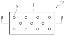
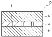
- FIG. 1A is a schematic top view showing an example of the composite of the present invention.
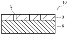
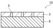
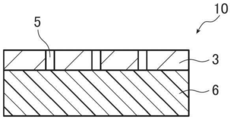
- FIG. 1B is a cross-sectional view taken along line BB of FIG. 1A.
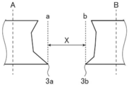
- FIG. 2A is a cross-sectional view of an aluminum base for explaining the average effective diameter of through holes.
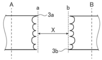
- FIG. 2B is a cross-sectional view of another aluminum base for illustrating the average effective diameter of the through holes.
- FIG. 3A is a schematic cross-sectional view of an aluminum base in a schematic cross-sectional view for explaining an example of a preferred method for producing a composite of the present invention.
- FIG. 1A is a schematic top view showing an example of the composite of the present invention.
- FIG. 1B is a cross-sectional view taken along line BB of FIG. 1A.
- FIG. 2A is a cross-sectional view of an aluminum base for explaining the average effective diameter of through holes.
- FIG. 2B is a cross-sectional view of another aluminum base for illustrating the average effective diameter of the
- FIG. 3B is a schematic cross-sectional view for explaining an example of a preferred method for producing the composite of the present invention, in which the aluminum base is subjected to a film forming treatment to form an aluminum hydroxide film on the surface. It is a typical sectional view showing.
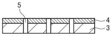
- FIG. 3C is a schematic cross-sectional view for explaining an example of a preferred method for producing the composite of the present invention, in which an electrochemical dissolution treatment is applied after the film formation treatment, and an aluminum substrate and an aluminum hydroxide film are provided. It is a typical sectional view showing the state where a penetration hole was formed in.
- FIG. 3C is a schematic cross-sectional view for explaining an example of a preferred method for producing the composite of the present invention, in which an electrochemical dissolution treatment is applied after the film formation treatment, and an aluminum substrate and an aluminum hydroxide film are provided. It is a typical sectional view showing the state where a penetration hole was formed in.
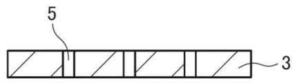
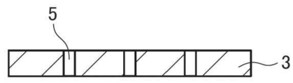
- FIG. 3D is a schematic cross-sectional view showing a state after removing the aluminum hydroxide film after the electrochemical solution treatment among the schematic cross-sectional views for explaining an example of the preferable method for producing the composite of the present invention.
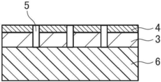
- FIG. 3E shows a state in which a resin layer is formed on one surface after removing the aluminum hydroxide film in a schematic cross-sectional view for explaining an example of a preferred method for producing the composite of the present invention. It is a typical sectional view.
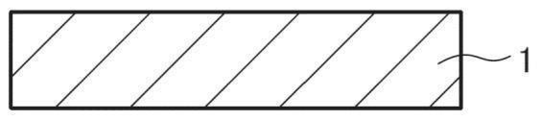
- FIG. 4A is a schematic cross-sectional view of an aluminum base in a schematic cross-sectional view for explaining another example of the preferred method for producing the composite of the present invention.
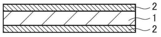
- FIG. 4B is a schematic cross-sectional view for explaining another example of the preferred method for producing the composite of the present invention, in which the aluminum base is subjected to a film formation treatment, and an aluminum hydroxide film is provided on the front and back surfaces. It is a typical sectional view showing the formed state.
- FIG. 4C is a schematic cross-sectional view for explaining another example of the preferred method for producing the composite of the present invention, in which an electrochemical dissolution treatment is carried out after the film formation treatment, and an aluminum substrate and hydroxylation are carried out. It is a schematic cross section which shows the state which formed the through-hole in the aluminum film.
- FIG. 4C is a schematic cross-sectional view for explaining another example of the preferred method for producing the composite of the present invention, in which an electrochemical dissolution treatment is carried out after the film formation treatment, and an aluminum substrate and hydroxylation are carried out. It is a schematic cross section which shows the state which formed the through-hole in the aluminum film.
- FIG. 4D shows a state after removing the aluminum hydroxide film after the electrochemical dissolution treatment in a schematic cross-sectional view for explaining another example of a preferred method for producing the composite of the present invention. It is a typical sectional view.
- FIG. 4E shows a state in which a resin layer is formed on both sides after removing the aluminum hydroxide film in a schematic cross-sectional view for explaining another example of the preferred method for producing the composite of the present invention. It is a typical sectional view.
- FIG. 5A is a schematic cross-sectional view of an aluminum base in a schematic cross-sectional view for explaining another example of the preferred method for producing the composite of the present invention.
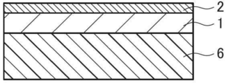
- FIG. 5B is a schematic cross-sectional view showing a state in which a resin layer is formed on one surface of an aluminum base in a schematic cross-sectional view for explaining another example of the preferred method for producing the composite of the present invention.
- FIG. 5C is a schematic cross-sectional view for explaining another example of the preferred method for producing the composite of the present invention, in which the film formation treatment is applied to the surface of the aluminum base on the side where the resin layer is not formed. It is typical sectional drawing which shows the state which was given and the aluminum hydroxide film was formed in the surface.
- FIG. 5B is a schematic cross-sectional view showing a state in which a resin layer is formed on one surface of an aluminum base in a schematic cross-sectional view for explaining another example of the preferred method for producing the composite of the present invention.
- FIG. 5C is a schematic cross-sectional view for explaining another example of the preferred method for producing the composite of the present invention, in which the film formation treatment is applied to the surface of the aluminum base on the side where the
- FIG. 5D is a schematic cross-sectional view for explaining another example of the preferred method for producing the composite of the present invention, in which an electrochemical dissolution treatment is applied after the film formation treatment, and an aluminum substrate and hydroxylation are carried out. It is a schematic cross section which shows the state which formed the through-hole in the aluminum film.
- FIG. 5E shows a state after removing the aluminum hydroxide film after the electrochemical dissolution treatment in a schematic cross-sectional view for explaining another example of the preferred method for producing the composite of the present invention. It is a typical sectional view.
- a numerical range represented using “to” means a range including numerical values described before and after “to” as the lower limit value and the upper limit value.
- the composite of the present invention has an aluminum base having a plurality of through holes in the thickness direction, and a resin layer provided on at least one surface of the aluminum base.
- the average opening diameter of the through holes is 0.1 to 100 ⁇ m.
- the composite of the present invention has an average open area ratio of 1 to 50% by the through holes.
- the average opening diameter of the through holes is obtained by photographing the surface of the aluminum substrate at a magnification of 100 to 10000 times from directly above using a high resolution scanning electron microscope (SEM).
- SEM scanning electron microscope
- the magnification of the range mentioned above can be suitably selected so that the SEM photograph which can extract 20 or more through holes can be obtained.
- the opening diameter measured the maximum value of the distance between the ends of the through-hole part.
- the shape of the opening of the through hole is not limited to a substantially circular shape, when the shape of the opening is non-circular, the maximum value of the distance between the end portions of the through holes is taken as the opening diameter. Therefore, for example, even in the case of a through hole having a shape in which two or more through holes are integrated, this is regarded as one through hole, and the maximum value of the distance between the ends of the through hole portions is taken as the opening diameter. .
- the average aperture ratio by the through holes can be determined by placing a parallel light optical unit on one surface side of the aluminum substrate and transmitting parallel light, and using the optical microscope from the other surface of the aluminum substrate The surface of the material is photographed at a magnification of 100 times to obtain a photograph. From the sum of the aperture area of the through holes projected by the parallel light transmitted and the area (geometrical area) of the visual field, for the 100 mm ⁇ 75 mm visual field (5 places) in the range of 10 cm ⁇ 10 cm of the obtained photograph The ratio is calculated from the ratio (opening area / geometrical area), and the average value in each field of view (5 places) is calculated as the average opening ratio.
- appearance and light transmission are achieved by having an aluminum base having an average opening diameter and an average opening ratio of the through holes in the above-mentioned ranges and a resin layer provided on at least one surface of the aluminum base.
- a molded article excellent in any of the properties can be produced.
- the composite 10 shown in FIGS. 1A and 1B includes an aluminum base 3 having a plurality of through holes 5 in the thickness direction, and a resin layer 6 provided on one surface of the aluminum base 3.
- the wall surface of the through hole 5 has a surface perpendicular to the surface of the aluminum base 3.
- the hole wall surface of the through hole may have an uneven shape as shown in FIG.
- the resin layer 6 is provided on one surface of the aluminum base 3.
- both sides of the aluminum base 3 are provided. May have a resin layer.
- the aluminum base of the composite of the present invention is not particularly limited as long as it has a through hole described later, and, for example, 3000 series (eg, 3003 material etc.), 8000 series (eg, 8021 material etc.), etc.
- Known aluminum alloys can be used.
- an aluminum alloy for example, an aluminum alloy having an alloy number shown in Table 1 below can be used.
- the average opening diameter of the through holes is 0.1 to 100 ⁇ m, and the average opening ratio by the through holes is 1 to 50%.
- the average opening diameter of the through holes is preferably 1 to 100 ⁇ m and more preferably 1 to 70 ⁇ m from the viewpoints of adhesion to a resin layer described later, tensile strength, visibility of the through holes, etc.
- it is 1 to 40 ⁇ m.
- the average aperture ratio by the through holes is preferably 2 to 45%, more preferably 2 to 30%, from the viewpoints of adhesion to a resin layer described later, tensile strength, light transmittance and the like. And 5 to 30% is more preferable, and 10 to 30% is particularly preferable.
- the average effective diameter of the through holes in the cross section cut in the direction perpendicular to the surface of the aluminum substrate is preferably 700 nm or more, and 800 nm or more, for better light transmission. Is more preferably 1 to 100 ⁇ m.
- the average effective diameter refers to the shortest distance between the wall surfaces of the through holes in the cross section cut in the direction perpendicular to the surface of the aluminum base, and as shown in FIGS. 2A and 2B, The average value of the distance X between the perpendicular a at the point 3a where the distance from the reference line A is maximum on the wall and the perpendicular b at the point 3b where the distance from the reference line B at the right hole wall of the through hole is maximum .
- the average effective diameter is determined by placing a parallel light optical unit on one side of the aluminum base and transmitting parallel light, and using the optical microscope from the other side of the aluminum base, using an optical microscope. The surface of the material is photographed at a magnification of 100 times to obtain a photograph. With respect to 100 mm ⁇ 75 mm visual fields (5 places) in the range of 10 cm ⁇ 10 cm of the obtained photograph, 20 through holes projected by the transmitted parallel light are extracted in each visual field. The diameter of a total of 100 extracted through holes is measured, and the average value of these is calculated as an average effective diameter.
- the average thickness of the aluminum base is preferably 5 to 1000 ⁇ m, more preferably 5 to 50 ⁇ m, and still more preferably 8 to 30 ⁇ m from the viewpoint of handling.
- the average thickness of the aluminum substrate refers to the average value of the thickness at which any five points are measured using a contact-type film thickness meter (digital electronic micrometer).
- the resin layer contained in the composite of the present invention is not particularly limited as long as it is a layer formed of a resin material having transparency, and examples of the resin material include polyester, polyolefin, and the like.
- the polyester include polyethylene terephthalate (PET) and polyethylene naphthalate.
- Specific examples of other resin materials include, for example, polyamide, polyether, polystyrene, polyesteramide, polycarbonate, polyphenylene sulfide, polyetherester, polyvinyl chloride, polyacrylic ester, polymethacrylic ester and the like.
- “having transparency” indicates that the transmittance of visible light is 60% or more, preferably 80% or more, and particularly preferably 90% or more.
- the average thickness of the resin layer is preferably 12 to 200 ⁇ m, more preferably 12 to 100 ⁇ m, still more preferably 25 to 100 ⁇ m, and further preferably 50 to 100 ⁇ m from the viewpoint of handling and processability. Particular preference is given to Here, the average thickness of the resin layer refers to the average value of the thickness obtained by measuring any five points using a contact-type film thickness meter (digital electronic micrometer).
- the method for producing the composite of the present invention is not particularly limited, for example, after the film forming step of forming an aluminum hydroxide film on at least one surface of the aluminum base and the film forming step, A resin is formed on at least one surface of an aluminum substrate having a through hole after the through hole forming step of forming the through hole, the film removing step of removing the aluminum hydroxide film after the through hole forming step, and the film removing step Method including a resin layer forming step of forming a layer (hereinafter also referred to as “manufacturing method A”); resin layer forming step of forming a resin layer on one surface of an aluminum base, and after resin layer forming step After the film forming step, forming an aluminum hydroxide film on the surface of the aluminum base on the side where the resin layer is not provided; A method having a through hole forming step of forming a through hole, and a film removing step of removing an aluminum hydroxide film after the through hole forming step (her
- FIGS. 3A to 3E and FIGS. 4A to 4E are schematic cross-sectional views showing an example of a preferred embodiment of the method A for producing a composite.
- the method for producing a composite performs a film forming treatment on one surface (both sides in the embodiment shown in FIG. 4) of the aluminum substrate 1. 3A and 3B, and FIGS. 4A and 4B, forming the aluminum hydroxide film 2 and the electrolytic solution treatment after the film forming process to form the through holes 5, and aluminum having the through holes A through-hole forming step (FIGS.
- the method B of producing a composite includes a resin layer forming step (FIGS. 5A and 5B) of forming a resin layer 6 on one surface of the aluminum base 1 and an aluminum group.
- a film forming process is performed on the surface of the material 1 on which the resin layer 6 is not formed to form an aluminum hydroxide film 2 (FIGS. 5B and 5C), and electrolytic dissolution is performed after the film forming process.
- a through hole is formed to form a laminate having an aluminum base 3 having a through hole, an aluminum hydroxide film 4 having a through hole, and a resin layer 6 not having a through hole.
- the aluminum hydroxide film 4 having the through hole is removed, and the aluminum base 3 having the through hole and the resin layer 6 having no through hole Have and It is a manufacturing method and a film removal step of preparing a polymer (FIGS. 5D and 5E).
- the film formation step is a step of forming a film of aluminum hydroxide by subjecting the surface of the aluminum substrate to a film formation treatment.
- the film formation process is not particularly limited, and, for example, the same process as the conventionally known aluminum hydroxide film formation process can be performed.
- the film formation process for example, the conditions and apparatus described in paragraphs [0013] to [0026] of JP-A-2011-201123 can be appropriately adopted.
- the conditions of the film formation treatment can not be determined indiscriminately because they vary depending on the electrolyte used, but generally, the electrolyte concentration is 1 to 80 mass%, the solution temperature is 5 to 70 ° C. It is appropriate that the current density is 0.5 to 60 A / dm 2 , the voltage is 1 to 100 V, and the electrolysis time is 1 second to 20 minutes, and it is adjusted to obtain a desired amount of film.
- electrochemical treatment using nitric acid, hydrochloric acid, sulfuric acid, phosphoric acid or oxalic acid, or a mixed acid of two or more of these acids as an electrolytic solution.
- direct current may be applied between the aluminum base and the counter electrode, and alternating current may be applied.
- the current density is preferably 1 to 60 A / dm 2 , more preferably 5 to 50 A / dm 2 .
- the amount of the aluminum hydroxide film formed by the film forming treatment is preferably 0.05 to 50 g / m 2 , and more preferably 0.1 to 10 g / m 2 .
- the through hole forming step is a step of performing electrolytic dissolution treatment after the film forming step to form a through hole.
- the electrolytic dissolution treatment is not particularly limited, and an acidic solution can be used as the electrolytic solution using direct current or alternating current.
- electrochemical treatment is preferably performed using at least one of nitric acid and hydrochloric acid, and electrochemical treatment is performed using a mixed acid obtained by adding at least one or more acids of sulfuric acid, phosphoric acid and oxalic acid to these acids. It is more preferable to
- the concentration of the acidic solution is preferably 0.1 to 2.5% by mass, particularly preferably 0.2 to 2.0% by mass.
- the liquid temperature of the acidic solution is preferably 20 to 80 ° C., and more preferably 30 to 60 ° C.
- the aqueous solution mainly composed of the acid is a nitrate compound having nitrate ion such as aluminum nitrate, sodium nitrate and ammonium nitrate in an aqueous solution of acid having a concentration of 1 to 100 g / L or hydrochloric acid such as aluminum chloride, sodium chloride and ammonium chloride.
- a hydrochloric acid compound having an ion and a sulfate compound having a sulfate ion such as aluminum sulfate, sodium sulfate and ammonium sulfate can be added and used in a range from 1 g / L to saturation.
- mainly contained means that the component which becomes the main component in the aqueous solution is contained in an amount of 30% by mass or more, preferably 50% by mass or more, with respect to the entire components added to the aqueous solution.
- the metal contained in aluminum alloys such as iron, copper, manganese, nickel, titanium, magnesium, a silica, may be melt
- the alternating current power source wave is not particularly limited when using alternating current, and sine wave, rectangular wave, trapezoidal wave, triangular wave or the like is used, Among them, rectangular waves or trapezoidal waves are preferable, and trapezoidal waves are particularly preferable.
- nitric acid electrolysis In the present invention, penetration which makes the average opening diameter be 0.1 ⁇ m or more and less than 100 ⁇ m easily by electrochemical dissolution treatment using an electrolyte mainly composed of nitric acid (hereinafter also referred to as “nitric acid dissolution treatment”). Holes can be formed.
- the average current density is preferably 100 A / dm 2 or less, and the amount of electricity is preferably 10000 C / dm 2 or less.
- concentration and temperature of the electrolyte in nitric acid electrolysis are not particularly limited, and electrolysis is performed at 30 to 60 ° C. using a high concentration nitric acid electrolyte having a nitric acid concentration of 15 to 35 mass%, for example. Electrolysis can be performed at a high temperature, for example, 80 ° C. or higher, using a 7 to 2% by mass nitric acid electrolyte. In addition, electrolysis can be performed using an electrolytic solution obtained by mixing at least one of sulfuric acid, oxalic acid and phosphoric acid at a concentration of 0.1 to 50% by mass with the above nitric acid electrolytic solution.
- a through-hole having an average opening diameter of 1 ⁇ m or more and less than 100 ⁇ m can be easily obtained by electrochemical dissolution treatment using an electrolytic solution mainly composed of hydrochloric acid (hereinafter also abbreviated as “hydrochloric acid dissolution treatment”).
- hydrochloric acid dissolution treatment the condition that the average current density is 5 A / dm 2 or more and the amount of electricity is 50 C / dm 2 or more using a direct current because it is easy to control the dissolution point of through hole formation It is preferable that it is the electrolytic treatment given by.
- the average current density is preferably 100 A / dm 2 or less, and the amount of electricity is preferably 10000 C / dm 2 or less.
- the concentration and temperature of the electrolytic solution in hydrochloric acid electrolysis are not particularly limited, and electrolysis is carried out at 30 to 60 ° C. using a high concentration, for example, a hydrochloric acid electrolytic solution having a hydrochloric acid concentration of 10 to 35 mass%.
- the electrolysis can be performed at a high temperature, for example, 80 ° C. or more, using a 7 to 2% by mass hydrochloric acid electrolyte solution. Further, electrolysis can be performed using an electrolytic solution obtained by mixing at least one of sulfuric acid, oxalic acid and phosphoric acid at a concentration of 0.1 to 50% by mass with the above-mentioned hydrochloric acid electrolytic solution.
- the film removal step is a step of chemical dissolution treatment to remove the aluminum hydroxide film.
- the aluminum hydroxide film can be removed by performing an acid etching treatment or an alkali etching treatment described later.
- the solution treatment is a treatment in which an aluminum hydroxide film is dissolved using a solution in which aluminum hydroxide is preferentially dissolved in preference to aluminum (hereinafter referred to as “aluminum hydroxide solution”).
- the aluminum hydroxide solution for example, nitric acid, hydrochloric acid, sulfuric acid, phosphoric acid, oxalic acid, chromium compound, zirconium compound, titanium compound, lithium salt, cerium salt, magnesium salt, sodium silicofluoride, fluoride fluoride
- An aqueous solution containing at least one selected from the group consisting of zinc, a manganese compound, a molybdenum compound, a magnesium compound, a barium compound and a halogen alone is preferred.
- chromium compound for example, chromium (III) oxide, chromium (VI) anhydride and the like can be mentioned.
- zirconium-based compound include ammonium zirconium fluoride, zirconium fluoride and zirconium chloride.
- titanium compounds include titanium oxide and titanium sulfide.
- lithium salts include lithium fluoride and lithium chloride.
- cerium salt include cerium fluoride and cerium chloride.
- magnesium salt magnesium sulfide is mentioned, for example.
- manganese compounds include sodium permanganate and calcium permanganate.
- molybdenum compound sodium molybdate is mentioned, for example.
- magnesium fluoride pentahydrate is mentioned, for example.
- a barium compound for example, barium oxide, barium acetate, barium carbonate, barium chlorate, barium chloride, barium fluoride, barium iodide, barium lactate, barium oxalate, barium perchlorate, barium selenate, selenious acid
- barium stearate, barium sulfite, barium titanate, barium hydroxide, barium nitrate, and hydrates of these barium oxide, barium acetate and barium carbonate are preferred, and barium oxide is particularly preferred.
- the halogen alone include chlorine, fluorine and bromine.
- the above-mentioned aluminum hydroxide solution is preferably an aqueous solution containing an acid
- the acid include nitric acid, hydrochloric acid, sulfuric acid, phosphoric acid, oxalic acid and the like, and even a mixture of two or more acids. Good.
- nitric acid it is preferable to use nitric acid as the acid.
- the acid concentration is preferably 0.01 mol / L or more, more preferably 0.05 mol / L or more, and still more preferably 0.1 mol / L or more.
- the upper limit is not particularly limited, but generally 10 mol / L or less is preferable, and 5 mol / L or less is more preferable.
- the dissolution treatment is carried out by bringing the aluminum base on which the aluminum hydroxide film is formed into contact with the above-mentioned solution.
- the method for contacting is not particularly limited, and examples thereof include a dipping method and a spraying method. Among them, the immersion method is preferred.
- the immersion method is a process of immersing the aluminum base on which the aluminum hydroxide film is formed in the above-described solution. Stirring during the immersion treatment is preferable because the treatment without unevenness is performed.
- the immersion treatment time is preferably 10 minutes or more, more preferably 1 hour or more, and still more preferably 3 hours or more and 5 hours or more.
- the alkali etching treatment is a treatment in which the surface layer is dissolved by bringing the aluminum hydroxide film into contact with an alkali solution.
- alkali used for the alkali solution examples include caustic alkali and alkali metal salts.
- caustic alkali examples include sodium hydroxide (caustic soda) and caustic potash.
- alkali metal salt for example, alkali metal silicates such as sodium metasilicate, sodium silicate, potassium metasilicate and potassium silicate; alkali metal carbonates such as sodium carbonate and potassium carbonate; sodium aluminate, aluminum Alkali metal aluminates such as potassium hydroxide; alkali metal aldonates such as sodium gluconate and potassium gluconate; sodium dibasic phosphate, potassium dibasic phosphate, sodium tribasic phosphate, potassium tribasic phosphate and the like And alkali metal hydrogen phosphates.
- a solution of caustic alkali and a solution containing both caustic alkali and an alkali metal aluminate are preferable from the viewpoint of high etching rate and low cost.
- an aqueous solution of sodium hydroxide is preferred.
- the concentration of the alkaline solution is preferably 0.1 to 50% by mass, and more preferably 0.2 to 10% by mass.
- concentration of aluminum ions is preferably 0.01 to 10% by mass, and more preferably 0.1 to 3% by mass.
- the temperature of the alkaline solution is preferably 10 to 90.degree.
- the treatment time is preferably 1 to 120 seconds.
- a method of bringing an aluminum hydroxide film into contact with an alkaline solution for example, a method of passing an aluminum base on which an aluminum hydroxide film is formed through a tank containing an alkaline solution, aluminum on which an aluminum hydroxide film is formed There is a method of immersing the substrate in a bath containing an alkaline solution, and a method of spraying the alkaline solution onto the surface (aluminum hydroxide film) of the aluminum substrate on which the aluminum hydroxide film is formed.
- the resin layer forming step is a step of forming a resin layer on the surface of the aluminum base having a through hole after the film removing step in the manufacturing method A, and in the manufacturing method B, no through hole is formed. It is a process of forming a resin layer on an aluminum substrate.
- the method to form a resin layer is not specifically limited, For example, dry lamination, wet lamination, extrusion lamination, an inflation lamination method etc. are mentioned. Among these, as described above, the embodiment in which the average thickness of the resin layer is 12 to 200 ⁇ m (particularly 25 to 100 ⁇ m) and the embodiment in which the average thickness of the aluminum base is 5 to 1000 ⁇ m are preferred embodiments.
- the method of forming a resin layer by dry lamination is preferable. As the dry lamination, for example, the conditions and devices described in paragraphs [0067] to [0078] of JP-A-2013-121673 can be appropriately adopted.
- Example 1 ⁇ Production of aluminum base> The surface of an aluminum base (JIS H-4160, alloy number: 1085-H, aluminum purity: 99.85%) with an average thickness of 20 ⁇ m and a size of 200 mm ⁇ 300 mm is treated as described below to have through holes An aluminum base was produced.
- A1 Aluminum hydroxide film formation treatment (film formation process) Using an electrolytic solution kept at 50 ° C. (nitric acid concentration 1%, sulfuric acid concentration 0.2%, aluminum concentration 0.5%), the above aluminum base material is subjected to electrolytic treatment as a cathode, and the aluminum base material is hydroxylated An aluminum film was formed. In addition, the electrolysis process was performed by direct-current power supply.
- the direct current density was 33 A / dm 2 and applied for 30 seconds. After the formation of the aluminum hydroxide film, washing with water by spraying was performed. It was 1.5 micrometers when the thickness of the aluminum hydroxide film
- Electrolytic dissolution treatment through hole forming step
- the current density is made 25 A / dm 2 by using the aluminum base as an anode.
- the electrolytic treatment was performed under the condition of the total amount of 700 C / dm 2 to form through holes in the aluminum base and the aluminum hydroxide film.
- the electrolysis process was performed by direct-current power supply. After the formation of the through holes, the plate was rinsed with a spray and dried.
- Example 2 A composite was produced in the same manner as in Example 1 except that in the electrolytic solution treatment (b1) of Example 1, the total amount of electricity was changed to 850 C / dm 2 .
- Example 3 A composite was produced in the same manner as in Example 1 except that in the electrolytic dissolution treatment (b1) in Example 1, the total amount of electricity was changed to 1400 C / dm 2 .
- Example 4 A composite was produced in the same manner as in Example 1 except that in the electrolytic solution treatment (b1) of Example 1, the total amount of electricity was changed to 1800 C / dm 2 .
- Comparative Example 1 An aluminum substrate was prepared according to the method described in WO 2008/078777. Specifically, for an aluminum foil (thickness: 20 ⁇ m) with uniform crystal orientation, the temperature of the hydrochloric acid electrolyte and the amount of electricity of the electrolytic treatment are adjusted to produce an aluminum substrate having through holes with an average opening diameter of 3 ⁇ m. did. A resin layer was formed in the same manner as in Example 1 except that the produced aluminum base was used, to produce a composite.
- Comparative Example 2 An aluminum substrate was prepared according to the method described in WO 2008/078777. Specifically, a pattern is formed on the surface of a hard aluminum foil (thickness: 20 ⁇ m) by resist printing, and a chemical etching treatment is performed with an alkaline processing solution to obtain aluminum having a through hole with an average opening diameter of 110 ⁇ m. A substrate was made. A resin layer was formed in the same manner as in Example 1 except that the produced aluminum base was used, to produce a composite.
- Comparative Example 3 An aluminum substrate was prepared according to the method described in WO 2008/078777. Specifically, through holes (average opening diameter: 300 ⁇ m) were mechanically formed by a punching die on a hard aluminum foil (thickness: 20 ⁇ m) to produce an aluminum base. A resin layer was formed in the same manner as in Example 1 except that the produced aluminum base was used, to produce a composite.
- Example 5 After producing an aluminum base by the same method as Comparative Example 1, after immersing in an aqueous solution (sodium hydroxide concentration 5 mass%, aluminum ion concentration 0.5 mass%) (liquid temperature 35 ° C.) for 120 seconds, sulfuric acid The aluminum base having a through hole with an average opening diameter of 15 ⁇ m was produced by immersing in an aqueous solution having a concentration of 30% and an aluminum ion concentration of 0.5% by mass (a liquid temperature of 50 ° C.) for 20 seconds. A resin layer was formed in the same manner as in Example 1 except that the produced aluminum base was used, to produce a composite.
- Example 6 Japanese Patent Application Laid-Open No. 2013-121673 on one surface of an aluminum base (JIS H-4160, alloy number: 1085-H, aluminum purity: 99.85%) having an average thickness of 9.0 ⁇ m and a size of 200 mm ⁇ 300 mm.
- JIS H-4160, alloy number: 1085-H, aluminum purity: 99.85% having an average thickness of 9.0 ⁇ m and a size of 200 mm ⁇ 300 mm.
- a 125 ⁇ m-thick PET was laminated as a resin layer by the method described in Thereafter, the following treatment was performed to prepare a complex.
- A2 Aluminum hydroxide film formation treatment (film formation step)
- the electrolytic treatment was performed using an electrolytic solution (nitric acid concentration 1%, sulfuric acid concentration 0.2%, aluminum concentration 0.5%) kept at 50 ° C., using the aluminum substrate as a cathode, and the side not provided with PET An aluminum hydroxide film was formed on the surface of the aluminum substrate of
- the electrolysis process was performed by direct-current power supply.
- the direct current density was 55 A / dm 2 and applied for 30 seconds.
- washing with water by spraying was performed. It was 1.5 micrometers when the thickness of the aluminum hydroxide film
- FIB focused ion beam
- Electrolytic dissolution treatment (through hole forming step) Then, using an electrolytic solution kept at 50 ° C. (nitric acid concentration 1%, sulfuric acid concentration 0.2%, aluminum concentration 0.5%), the aluminum substrate is made to be an anode, and the current density is 35 A / dm 2.
- the electrolytic treatment was performed under the condition of the total amount of 400 C / dm 2 to form through holes in the aluminum base and the aluminum hydroxide film.
- the electrolysis process was performed by direct-current power supply. After the formation of the through holes, the plate was rinsed with a spray and dried.
- a light emitting diode (LED) light (SG-355B: made by GENTOS) is placed at a distance of 4 cm below the PET sheet in the same environment as the appearance test described above, and the observer lights the PET sheet.
- a test was conducted to see if it could recognize written characters. The above test was conducted by 10 persons and evaluated according to the following criteria. For practical use, the evaluation is preferably 1 to 3, and more preferably 1 or 2. 1: The number of people who can recognize letters is 9 to 10. The number of people who can recognize letters is 6 to 8. The number of people who can recognize letters is 2 to 5 4: The number of people who can recognize letters is 0 to 1
- the composite of the present invention is used for photocatalysts, hydrogen generation catalysts, enzyme electrodes, noble metal absorbent carriers, antibacterial carriers, adsorbents, absorptions, in addition to uses for molded articles such as metallic decorative bodies used for lighting applications. It can also be used as an agent, an optical filter, a far infrared cut filter, a soundproof / sound absorbing material, an electromagnetic wave shield, a building material, etc.
Landscapes
- Chemical & Material Sciences (AREA)
- Engineering & Computer Science (AREA)
- Chemical Kinetics & Catalysis (AREA)
- Electrochemistry (AREA)
- Materials Engineering (AREA)
- Metallurgy (AREA)
- Organic Chemistry (AREA)
- Laminated Bodies (AREA)
- ing And Chemical Polishing (AREA)
Abstract
Priority Applications (4)
| Application Number | Priority Date | Filing Date | Title |
|---|---|---|---|
| JP2018502972A JP6563583B2 (ja) | 2016-02-29 | 2017-02-07 | 金属調装飾体成型用複合体 |
| CN201780013628.7A CN108698360B (zh) | 2016-02-29 | 2017-02-07 | 复合体 |
| EP17759570.9A EP3424697A4 (fr) | 2016-02-29 | 2017-02-07 | Corps composite |
| US16/111,393 US20180361710A1 (en) | 2016-02-29 | 2018-08-24 | Composite body |
Applications Claiming Priority (4)
| Application Number | Priority Date | Filing Date | Title |
|---|---|---|---|
| JP2016037897 | 2016-02-29 | ||
| JP2016-037897 | 2016-02-29 | ||
| JP2017005394 | 2017-01-16 | ||
| JP2017-005394 | 2017-01-16 |
Related Child Applications (1)
| Application Number | Title | Priority Date | Filing Date |
|---|---|---|---|
| US16/111,393 Continuation US20180361710A1 (en) | 2016-02-29 | 2018-08-24 | Composite body |
Publications (1)
| Publication Number | Publication Date |
|---|---|
| WO2017150099A1 true WO2017150099A1 (fr) | 2017-09-08 |
Family
ID=59743788
Family Applications (1)
| Application Number | Title | Priority Date | Filing Date |
|---|---|---|---|
| PCT/JP2017/004406 Ceased WO2017150099A1 (fr) | 2016-02-29 | 2017-02-07 | Corps composite |
Country Status (6)
| Country | Link |
|---|---|
| US (1) | US20180361710A1 (fr) |
| EP (1) | EP3424697A4 (fr) |
| JP (1) | JP6563583B2 (fr) |
| CN (1) | CN108698360B (fr) |
| TW (1) | TW201800254A (fr) |
| WO (1) | WO2017150099A1 (fr) |
Cited By (4)
| Publication number | Priority date | Publication date | Assignee | Title |
|---|---|---|---|---|
| WO2019066011A1 (fr) | 2017-09-29 | 2019-04-04 | 富士フイルム株式会社 | Stratifié |
| WO2019142588A1 (fr) * | 2018-01-17 | 2019-07-25 | 富士フイルム株式会社 | Stratifié, composite et procédé de fabrication de composite |
| WO2020044900A1 (fr) * | 2018-08-29 | 2020-03-05 | 富士フイルム株式会社 | Film protecteur et appareil d'affichage d'image |
| WO2020066597A1 (fr) * | 2018-09-26 | 2020-04-02 | 富士フイルム株式会社 | Corps stratifié |
Families Citing this family (1)
| Publication number | Priority date | Publication date | Assignee | Title |
|---|---|---|---|---|
| KR102239441B1 (ko) * | 2018-08-22 | 2021-04-12 | 주식회사 엘지화학 | 마스크 필름을 이용한 편광판의 제조방법 및 그 편광판 |
Citations (20)
| Publication number | Priority date | Publication date | Assignee | Title |
|---|---|---|---|---|
| US4184932A (en) | 1977-09-29 | 1980-01-22 | Hoechst Aktiengesellschaft | Electropolishing process |
| US4336113A (en) | 1981-06-26 | 1982-06-22 | American Hoechst Corporation | Electrolytic graining of aluminum with hydrogen peroxide and nitric or hydrochloric acid |
| US4374710A (en) | 1982-03-18 | 1983-02-22 | American Hoechst Corporation | Electrolytic graining of aluminum with nitric and oxalic acids |
| US4416972A (en) | 1981-06-26 | 1983-11-22 | American Hoechst Corporation | Electrolytic graining of aluminum with nitric and boric acids |
| US4566959A (en) | 1984-01-05 | 1986-01-28 | Hoechst Aktiengesellschaft | Process for the electrochemical roughening of aluminum useful for printing plate supports, in an aqueous mixed electrolyte |
| US4566960A (en) | 1984-01-05 | 1986-01-28 | Hoechst Aktiengesellschaft | Process for electrochemical roughening of aluminum useful for printing plate supports, in an aqueous mixed electrolyte |
| US4566958A (en) | 1984-01-05 | 1986-01-28 | Hoechst Aktiengesellschaft | Process for electrochemical roughening of aluminum useful for printing plate supports, in an aqueous mixed electrolyte |
| US4600482A (en) | 1984-04-25 | 1986-07-15 | Hoechst Aktiengesellschaft | Process for the electrochemical roughening of aluminum for use as printing plate supports, in an aqueous mixed electrolyte |
| US4618405A (en) | 1984-04-25 | 1986-10-21 | Hoechst Aktiengesellschaft | Process for the electrochemical roughening of aluminum for use as printing plate supports, in an aqueous mixed electrolyte |
| US4661219A (en) | 1985-02-06 | 1987-04-28 | Hoechst Aktiengesellschaft | Process for the electrochemical roughening of aluminum for use in printing plate supports |
| US4671859A (en) | 1985-09-20 | 1987-06-09 | Hoeschst Aktiengesellschaft | Process for the electrochemical graining of aluminum for use as printing plate supports |
| JPH0677920U (ja) * | 1993-04-19 | 1994-11-01 | マツダ工業株式会社 | 穿孔メタル及びそれを用いた複層板 |
| JP2005015867A (ja) | 2003-06-27 | 2005-01-20 | Yoshino Kogyosho Co Ltd | 加飾プラスチック成形品 |
| WO2008078777A1 (fr) | 2006-12-27 | 2008-07-03 | Jm Energy Corporation | Électrode revêtue et condensateur électrolytique organique |
| JP2010125466A (ja) * | 2008-11-26 | 2010-06-10 | Aru Techno:Kk | 極小孔加工板の製造方法 |
| JP2011201123A (ja) | 2010-03-25 | 2011-10-13 | Fujifilm Corp | 電解処理方法及び装置、並びに平版印刷版の製造方法及び装置 |
| JP2011216364A (ja) * | 2010-03-31 | 2011-10-27 | Toyo Aluminium Kk | 負極集電体用金属箔 |
| JP2013121673A (ja) | 2011-12-09 | 2013-06-20 | Fujifilm Corp | 積層シートの製造方法及び製造装置 |
| WO2015151756A1 (fr) * | 2014-03-31 | 2015-10-08 | 富士フイルム株式会社 | Composite de séparation de gaz et son procédé de fabrication |
| JP2015196280A (ja) | 2014-03-31 | 2015-11-09 | 株式会社吉野工業所 | 加飾樹脂成形品 |
Family Cites Families (5)
| Publication number | Priority date | Publication date | Assignee | Title |
|---|---|---|---|---|
| JPH0922699A (ja) * | 1995-07-06 | 1997-01-21 | Toshiba Battery Co Ltd | ポリマー電解質二次電池 |
| JP3045986U (ja) * | 1997-08-05 | 1998-02-20 | 有限会社サン・ブラスト | 写真画像表示プレート |
| JPH11311780A (ja) * | 1998-04-27 | 1999-11-09 | Kawaguchiko Seimitsu Kk | 液晶表示装置 |
| WO2015086032A1 (fr) * | 2013-12-13 | 2015-06-18 | Bang & Olufsen A/S | Motifs éclairés sur une surface |
| JP6405116B2 (ja) * | 2014-05-08 | 2018-10-17 | 株式会社アルテクノ | 金属製表示パネルの製造方法及び金属製表示パネル |
-
2017
- 2017-02-07 WO PCT/JP2017/004406 patent/WO2017150099A1/fr not_active Ceased
- 2017-02-07 JP JP2018502972A patent/JP6563583B2/ja active Active
- 2017-02-07 EP EP17759570.9A patent/EP3424697A4/fr not_active Withdrawn
- 2017-02-07 CN CN201780013628.7A patent/CN108698360B/zh active Active
- 2017-02-21 TW TW106105657A patent/TW201800254A/zh unknown
-
2018
- 2018-08-24 US US16/111,393 patent/US20180361710A1/en not_active Abandoned
Patent Citations (20)
| Publication number | Priority date | Publication date | Assignee | Title |
|---|---|---|---|---|
| US4184932A (en) | 1977-09-29 | 1980-01-22 | Hoechst Aktiengesellschaft | Electropolishing process |
| US4336113A (en) | 1981-06-26 | 1982-06-22 | American Hoechst Corporation | Electrolytic graining of aluminum with hydrogen peroxide and nitric or hydrochloric acid |
| US4416972A (en) | 1981-06-26 | 1983-11-22 | American Hoechst Corporation | Electrolytic graining of aluminum with nitric and boric acids |
| US4374710A (en) | 1982-03-18 | 1983-02-22 | American Hoechst Corporation | Electrolytic graining of aluminum with nitric and oxalic acids |
| US4566959A (en) | 1984-01-05 | 1986-01-28 | Hoechst Aktiengesellschaft | Process for the electrochemical roughening of aluminum useful for printing plate supports, in an aqueous mixed electrolyte |
| US4566960A (en) | 1984-01-05 | 1986-01-28 | Hoechst Aktiengesellschaft | Process for electrochemical roughening of aluminum useful for printing plate supports, in an aqueous mixed electrolyte |
| US4566958A (en) | 1984-01-05 | 1986-01-28 | Hoechst Aktiengesellschaft | Process for electrochemical roughening of aluminum useful for printing plate supports, in an aqueous mixed electrolyte |
| US4600482A (en) | 1984-04-25 | 1986-07-15 | Hoechst Aktiengesellschaft | Process for the electrochemical roughening of aluminum for use as printing plate supports, in an aqueous mixed electrolyte |
| US4618405A (en) | 1984-04-25 | 1986-10-21 | Hoechst Aktiengesellschaft | Process for the electrochemical roughening of aluminum for use as printing plate supports, in an aqueous mixed electrolyte |
| US4661219A (en) | 1985-02-06 | 1987-04-28 | Hoechst Aktiengesellschaft | Process for the electrochemical roughening of aluminum for use in printing plate supports |
| US4671859A (en) | 1985-09-20 | 1987-06-09 | Hoeschst Aktiengesellschaft | Process for the electrochemical graining of aluminum for use as printing plate supports |
| JPH0677920U (ja) * | 1993-04-19 | 1994-11-01 | マツダ工業株式会社 | 穿孔メタル及びそれを用いた複層板 |
| JP2005015867A (ja) | 2003-06-27 | 2005-01-20 | Yoshino Kogyosho Co Ltd | 加飾プラスチック成形品 |
| WO2008078777A1 (fr) | 2006-12-27 | 2008-07-03 | Jm Energy Corporation | Électrode revêtue et condensateur électrolytique organique |
| JP2010125466A (ja) * | 2008-11-26 | 2010-06-10 | Aru Techno:Kk | 極小孔加工板の製造方法 |
| JP2011201123A (ja) | 2010-03-25 | 2011-10-13 | Fujifilm Corp | 電解処理方法及び装置、並びに平版印刷版の製造方法及び装置 |
| JP2011216364A (ja) * | 2010-03-31 | 2011-10-27 | Toyo Aluminium Kk | 負極集電体用金属箔 |
| JP2013121673A (ja) | 2011-12-09 | 2013-06-20 | Fujifilm Corp | 積層シートの製造方法及び製造装置 |
| WO2015151756A1 (fr) * | 2014-03-31 | 2015-10-08 | 富士フイルム株式会社 | Composite de séparation de gaz et son procédé de fabrication |
| JP2015196280A (ja) | 2014-03-31 | 2015-11-09 | 株式会社吉野工業所 | 加飾樹脂成形品 |
Non-Patent Citations (1)
| Title |
|---|
| See also references of EP3424697A4 |
Cited By (11)
| Publication number | Priority date | Publication date | Assignee | Title |
|---|---|---|---|---|
| WO2019066011A1 (fr) | 2017-09-29 | 2019-04-04 | 富士フイルム株式会社 | Stratifié |
| KR20200044057A (ko) | 2017-09-29 | 2020-04-28 | 후지필름 가부시키가이샤 | 적층체 |
| CN111163931A (zh) * | 2017-09-29 | 2020-05-15 | 富士胶片株式会社 | 层叠体 |
| WO2019142588A1 (fr) * | 2018-01-17 | 2019-07-25 | 富士フイルム株式会社 | Stratifié, composite et procédé de fabrication de composite |
| CN111601705A (zh) * | 2018-01-17 | 2020-08-28 | 富士胶片株式会社 | 层叠体、复合体及复合体的制造方法 |
| JPWO2019142588A1 (ja) * | 2018-01-17 | 2021-01-07 | 富士フイルム株式会社 | 積層体、複合体および複合体の製造方法 |
| WO2020044900A1 (fr) * | 2018-08-29 | 2020-03-05 | 富士フイルム株式会社 | Film protecteur et appareil d'affichage d'image |
| CN112638643A (zh) * | 2018-08-29 | 2021-04-09 | 富士胶片株式会社 | 覆盖膜及图像显示装置 |
| JPWO2020044900A1 (ja) * | 2018-08-29 | 2021-09-09 | 富士フイルム株式会社 | カバーフイルムおよび画像表示装置 |
| WO2020066597A1 (fr) * | 2018-09-26 | 2020-04-02 | 富士フイルム株式会社 | Corps stratifié |
| JPWO2020066597A1 (ja) * | 2018-09-26 | 2021-08-30 | 富士フイルム株式会社 | 積層体 |
Also Published As
| Publication number | Publication date |
|---|---|
| TW201800254A (zh) | 2018-01-01 |
| JPWO2017150099A1 (ja) | 2018-12-13 |
| CN108698360B (zh) | 2021-03-23 |
| CN108698360A (zh) | 2018-10-23 |
| JP6563583B2 (ja) | 2019-08-21 |
| EP3424697A4 (fr) | 2019-01-16 |
| EP3424697A1 (fr) | 2019-01-09 |
| US20180361710A1 (en) | 2018-12-20 |
Similar Documents
| Publication | Publication Date | Title |
|---|---|---|
| JP6374013B2 (ja) | アルミニウム板 | |
| JP6563583B2 (ja) | 金属調装飾体成型用複合体 | |
| JP6199416B2 (ja) | アルミニウム板の製造方法、アルミニウム板、蓄電デバイス用集電体、蓄電デバイス、防音・吸音材、電磁波シールドおよび建築用材料 | |
| JP6592506B2 (ja) | アルミニウム板および蓄電デバイス用集電体 | |
| JP6328785B2 (ja) | アルミニウム板およびアルミニウム板の製造方法 | |
| JP6936864B2 (ja) | アルミニウム箔および電極用アルミニウム部材 | |
| US20200223186A1 (en) | Laminate | |
| WO2016017380A1 (fr) | Plaque d'aluminium | |
| US20220037671A1 (en) | Aluminum member for electrodes and method of producing aluminum member for electrodes | |
| WO2017018462A1 (fr) | Plaque d'aluminium et procédé permettant de produire une plaque d'aluminium | |
| JP2022015565A (ja) | アルミニウム部材及びその製造方法 | |
| WO2018061709A1 (fr) | Film | |
| JPWO2020044900A1 (ja) | カバーフイルムおよび画像表示装置 | |
| Bashirom et al. | Anodic ZrO2 Nanotube Arrays Formation by Anodisation in Ethylene Glycol with Varying Amount of Water |
Legal Events
| Date | Code | Title | Description |
|---|---|---|---|
| WWE | Wipo information: entry into national phase |
Ref document number: 2018502972 Country of ref document: JP |
|
| NENP | Non-entry into the national phase |
Ref country code: DE |
|
| WWE | Wipo information: entry into national phase |
Ref document number: 2017759570 Country of ref document: EP |
|
| ENP | Entry into the national phase |
Ref document number: 2017759570 Country of ref document: EP Effective date: 20181001 |
|
| 121 | Ep: the epo has been informed by wipo that ep was designated in this application |
Ref document number: 17759570 Country of ref document: EP Kind code of ref document: A1 |