WO2017150103A1 - Dispositif de traitement audio, dispositif de traitement d'image, système de réseau de microphones et procédé de traitement audio - Google Patents
Dispositif de traitement audio, dispositif de traitement d'image, système de réseau de microphones et procédé de traitement audio Download PDFInfo
- Publication number
- WO2017150103A1 WO2017150103A1 PCT/JP2017/004483 JP2017004483W WO2017150103A1 WO 2017150103 A1 WO2017150103 A1 WO 2017150103A1 JP 2017004483 W JP2017004483 W JP 2017004483W WO 2017150103 A1 WO2017150103 A1 WO 2017150103A1
- Authority
- WO
- WIPO (PCT)
- Prior art keywords
- voice
- sound
- unit
- audio
- emotion value
- Prior art date
- Legal status (The legal status is an assumption and is not a legal conclusion. Google has not performed a legal analysis and makes no representation as to the accuracy of the status listed.)
- Ceased
Links
Images





Classifications
-
- H—ELECTRICITY
- H04—ELECTRIC COMMUNICATION TECHNIQUE
- H04R—LOUDSPEAKERS, MICROPHONES, GRAMOPHONE PICK-UPS OR LIKE ACOUSTIC ELECTROMECHANICAL TRANSDUCERS; ELECTRIC HEARING AIDS; PUBLIC ADDRESS SYSTEMS
- H04R3/00—Circuits for transducers
-
- G—PHYSICS
- G10—MUSICAL INSTRUMENTS; ACOUSTICS
- G10L—SPEECH ANALYSIS TECHNIQUES OR SPEECH SYNTHESIS; SPEECH RECOGNITION; SPEECH OR VOICE PROCESSING TECHNIQUES; SPEECH OR AUDIO CODING OR DECODING
- G10L21/00—Speech or voice signal processing techniques to produce another audible or non-audible signal, e.g. visual or tactile, in order to modify its quality or its intelligibility
- G10L21/003—Changing voice quality, e.g. pitch or formants
- G10L21/007—Changing voice quality, e.g. pitch or formants characterised by the process used
- G10L21/013—Adapting to target pitch
-
- G—PHYSICS
- G10—MUSICAL INSTRUMENTS; ACOUSTICS
- G10L—SPEECH ANALYSIS TECHNIQUES OR SPEECH SYNTHESIS; SPEECH RECOGNITION; SPEECH OR VOICE PROCESSING TECHNIQUES; SPEECH OR AUDIO CODING OR DECODING
- G10L21/00—Speech or voice signal processing techniques to produce another audible or non-audible signal, e.g. visual or tactile, in order to modify its quality or its intelligibility
- G10L21/003—Changing voice quality, e.g. pitch or formants
-
- G—PHYSICS
- G10—MUSICAL INSTRUMENTS; ACOUSTICS
- G10L—SPEECH ANALYSIS TECHNIQUES OR SPEECH SYNTHESIS; SPEECH RECOGNITION; SPEECH OR VOICE PROCESSING TECHNIQUES; SPEECH OR AUDIO CODING OR DECODING
- G10L21/00—Speech or voice signal processing techniques to produce another audible or non-audible signal, e.g. visual or tactile, in order to modify its quality or its intelligibility
- G10L21/02—Speech enhancement, e.g. noise reduction or echo cancellation
- G10L21/0316—Speech enhancement, e.g. noise reduction or echo cancellation by changing the amplitude
- G10L21/0324—Details of processing therefor
- G10L21/034—Automatic adjustment
-
- G—PHYSICS
- G10—MUSICAL INSTRUMENTS; ACOUSTICS
- G10L—SPEECH ANALYSIS TECHNIQUES OR SPEECH SYNTHESIS; SPEECH RECOGNITION; SPEECH OR VOICE PROCESSING TECHNIQUES; SPEECH OR AUDIO CODING OR DECODING
- G10L25/00—Speech or voice analysis techniques not restricted to a single one of groups G10L15/00 - G10L21/00
- G10L25/48—Speech or voice analysis techniques not restricted to a single one of groups G10L15/00 - G10L21/00 specially adapted for particular use
- G10L25/51—Speech or voice analysis techniques not restricted to a single one of groups G10L15/00 - G10L21/00 specially adapted for particular use for comparison or discrimination
- G10L25/63—Speech or voice analysis techniques not restricted to a single one of groups G10L15/00 - G10L21/00 specially adapted for particular use for comparison or discrimination for estimating an emotional state
-
- H—ELECTRICITY
- H04—ELECTRIC COMMUNICATION TECHNIQUE
- H04R—LOUDSPEAKERS, MICROPHONES, GRAMOPHONE PICK-UPS OR LIKE ACOUSTIC ELECTROMECHANICAL TRANSDUCERS; ELECTRIC HEARING AIDS; PUBLIC ADDRESS SYSTEMS
- H04R1/00—Details of transducers, loudspeakers or microphones
- H04R1/20—Arrangements for obtaining desired frequency or directional characteristics
- H04R1/32—Arrangements for obtaining desired frequency or directional characteristics for obtaining desired directional characteristic only
- H04R1/40—Arrangements for obtaining desired frequency or directional characteristics for obtaining desired directional characteristic only by combining a number of identical transducers
-
- H—ELECTRICITY
- H04—ELECTRIC COMMUNICATION TECHNIQUE
- H04R—LOUDSPEAKERS, MICROPHONES, GRAMOPHONE PICK-UPS OR LIKE ACOUSTIC ELECTROMECHANICAL TRANSDUCERS; ELECTRIC HEARING AIDS; PUBLIC ADDRESS SYSTEMS
- H04R3/00—Circuits for transducers
- H04R3/005—Circuits for transducers for combining the signals of two or more microphones
-
- H—ELECTRICITY
- H04—ELECTRIC COMMUNICATION TECHNIQUE
- H04R—LOUDSPEAKERS, MICROPHONES, GRAMOPHONE PICK-UPS OR LIKE ACOUSTIC ELECTROMECHANICAL TRANSDUCERS; ELECTRIC HEARING AIDS; PUBLIC ADDRESS SYSTEMS
- H04R5/00—Stereophonic arrangements
- H04R5/04—Circuit arrangements, e.g. for selective connection of amplifier inputs/outputs to loudspeakers, for loudspeaker detection, or for adaptation of settings to personal preferences or hearing impairments
-
- G—PHYSICS
- G10—MUSICAL INSTRUMENTS; ACOUSTICS
- G10L—SPEECH ANALYSIS TECHNIQUES OR SPEECH SYNTHESIS; SPEECH RECOGNITION; SPEECH OR VOICE PROCESSING TECHNIQUES; SPEECH OR AUDIO CODING OR DECODING
- G10L21/00—Speech or voice signal processing techniques to produce another audible or non-audible signal, e.g. visual or tactile, in order to modify its quality or its intelligibility
- G10L21/003—Changing voice quality, e.g. pitch or formants
- G10L21/007—Changing voice quality, e.g. pitch or formants characterised by the process used
- G10L21/013—Adapting to target pitch
- G10L2021/0135—Voice conversion or morphing
-
- G—PHYSICS
- G10—MUSICAL INSTRUMENTS; ACOUSTICS
- G10L—SPEECH ANALYSIS TECHNIQUES OR SPEECH SYNTHESIS; SPEECH RECOGNITION; SPEECH OR VOICE PROCESSING TECHNIQUES; SPEECH OR AUDIO CODING OR DECODING
- G10L21/00—Speech or voice signal processing techniques to produce another audible or non-audible signal, e.g. visual or tactile, in order to modify its quality or its intelligibility
- G10L21/02—Speech enhancement, e.g. noise reduction or echo cancellation
- G10L21/0208—Noise filtering
- G10L21/0216—Noise filtering characterised by the method used for estimating noise
- G10L2021/02161—Number of inputs available containing the signal or the noise to be suppressed
- G10L2021/02166—Microphone arrays; Beamforming
Definitions
- the present disclosure relates to a sound processing device, an image processing device, a microphone array system, and a sound processing method.
- the directivity for the collected sound is formed in the directivity direction toward the sound position designated from the microphone array device.
- this system controls the output of the collected sound (mute processing, masking processing, or voice change processing), or pauses sound collection (Patent Literature). 1).
- This disclosure aims to detect the emotion of the speaker while protecting the privacy.
- the voice processing device includes an acquisition unit that acquires voice collected by a sound collection unit, a detection unit that detects a voice position of the voice, and a voice uttered when the voice position is within the privacy protection area.
- a determination unit that determines whether or not the voice is a voice, an analysis unit that analyzes the voice of the utterance to obtain an emotion value, a conversion unit that converts the voice of the utterance into an alternative output corresponding to the emotion value, and the voice
- An output control unit that outputs an alternative output to the output audio output unit;
- FIG. 1 is a block diagram showing the configuration of the microphone array system in the first embodiment.
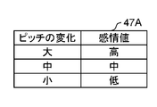
- FIG. 2A is a diagram illustrating registered contents of an emotion value table in which emotion values corresponding to pitch changes are registered.
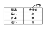
- FIG. 2B is a diagram showing registration contents of an emotion value table in which emotion values corresponding to speech speed are registered.
- FIG. 2C is a diagram illustrating registration contents of an emotion value table in which emotion values corresponding to sound volumes are registered.
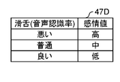
- FIG. 2D is a diagram illustrating registered contents of an emotion value table in which emotion values corresponding to the tongue are registered.
- FIG. 3 is a diagram showing registration contents of an alternative sound table in which corresponding alternative sounds corresponding to emotion values are registered.
- FIG. 1 is a block diagram showing the configuration of the microphone array system in the first embodiment.
- FIG. 2A is a diagram illustrating registered contents of an emotion value table in which emotion values corresponding to pitch changes are registered.
- FIG. 2B is a diagram showing registration contents of an emotion value table in which emotion values corresponding to
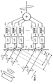
- FIG. 4 is an explanatory diagram of an example of the principle of forming directivity in a predetermined direction with respect to the sound collected by the microphone array device.
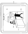
- FIG. 5 is a diagram showing an image representing a situation in which a conversation between the receptionist and a customer is picked up by a microphone array device installed at a store window.
- FIG. 6 is a flowchart showing a procedure for outputting sound collected by the microphone array apparatus.
- FIG. 7 is a block diagram showing a configuration of the microphone array system in the second embodiment.
- FIG. 8 is a diagram showing the registration contents of the alternative image table.
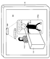
- FIG. 9 is a diagram showing an image representing a situation in which a conversation between the receptionist and a customer is picked up by a microphone array device installed at a store window.
- FIG. 9 is a diagram showing an image representing a situation in which a conversation between the receptionist and a customer is picked up by a microphone array device installed at a store window.
- FIG. 10 is a flowchart showing a procedure for outputting a video including a face icon based on the sound collected by the microphone array device.
- FIG. 11 is a block diagram illustrating a configuration of a microphone array system according to the third embodiment.
- FIG. 12 is a diagram showing an image representing a situation in which a conversation between the receptionist and a customer is picked up by a microphone array device installed at a store window.
- a voice processing device an image processing device, a microphone array system, and a voice processing method capable of detecting a speaker's emotion while protecting privacy will be described.
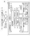
- FIG. 1 is a block diagram showing a configuration of a microphone array system 10 according to the first embodiment.
- the microphone array system 10 includes a camera device CA, a microphone array device MA, a recorder RC, and a directivity control device 30.
- the camera device CA, the microphone array device MA, the recorder RC, and the directivity control device 30 are connected to each other via a network NW so that data communication is possible.
- the network NW may be a wired network (for example, an intranet or the Internet) or a wireless network (for example, a wireless LAN (Local Area Network)).
- the camera device CA is a fixed camera with a fixed angle of view, for example, installed on a ceiling or wall in a room.
- the camera device CA functions as a surveillance camera that can image an imaging area SA (see FIG. 5), which is an imaging space in which the device itself is installed.
- the camera apparatus CA is not limited to a fixed camera, and may be an omnidirectional camera or a PTZ camera capable of pan / tilt / zoom operations.
- the camera device CA stores the time (image capturing time) when the image is captured in association with the image data, and transmits the image data to the directivity control device 30 via the network NW.
- the microphone array device MA is, for example, an omnidirectional microphone array device installed on an indoor ceiling.
- the microphone array device MA collects sound in all directions in the sound collection space (sound collection area) where the device itself is installed.
- the microphone array device MA includes a housing having an opening formed in the center, and a plurality of microphone units arranged concentrically around the opening in the circumferential direction.
- a microphone for example, a high sound quality small electret condenser microphone (ECM) is used.
- the imaging area and the sound collection area are substantially the same.
- the microphone array device MA stores the collected sound data in association with the time of sound collection (sound collection time), and directs the stored sound data and sound collection time data via the network NW. It transmits to the control apparatus 30.
- the directivity control device 30 is installed outside the room where the microphone array device MA and the camera device CA are installed, for example.
- the directivity control device 30 is, for example, a stationary PC (Personal Computer).
- the directivity control device 30 forms directivity for the omnidirectional sound collected by the microphone array device MA and emphasizes the sound in the directional direction.
- the directivity control device 30 estimates the position of a sound source (also referred to as an audio position) in the imaging area, and performs a predetermined mask process when the estimated position of the sound source is within the range of the privacy protection area. Details of the mask processing will be described later.
- the directivity control device 30 may be a communication terminal such as a mobile phone, a tablet terminal, or a smartphone instead of the PC.
- the directivity control device 30 includes a communication unit 31, an operation unit 32, a signal processing unit 33, a display device 36, a speaker device 37, a memory 38, a setting management unit 39, and a voice analysis unit 45. It is the structure which contains at least.
- the signal processing unit 33 includes a directivity control unit 41, a privacy determination unit 42, an utterance determination unit 34, and an output control unit 35.
- the setting management unit 39 sets the coordinates of the privacy protection area designated by the user from the microphone array device MA to the privacy protection area for the image captured by the camera device CA displayed on the display device 36.
- the angle is converted into an angle indicating a directivity direction toward the corresponding voice area.
- the setting management unit 39 calculates a directivity angle ( ⁇ MAh, ⁇ MAv) from the microphone array device MA toward the voice area corresponding to the privacy protection area in accordance with the designation of the privacy protection area. Details of this calculation processing are described in, for example, Patent Document 1.
- ⁇ MAh represents the horizontal angle of the directivity direction from the microphone array device MA toward the voice position.
- ⁇ MAv represents the vertical angle of the directivity direction from the microphone array device MA toward the sound position.
- the audio position is an actual position corresponding to a designated position designated by the user's finger or stylus pen in the video data displayed on the display device 36 by the operation unit 32. This conversion process may be performed by the signal processing unit 33.
- the setting management unit 39 has a memory 39z.
- the setting management unit 39 obtains the coordinates of the privacy protection area designated by the user and the coordinates indicating the directivity direction toward the audio area corresponding to the converted privacy protection area for the image captured by the camera device CA. Store in the memory 39z.
- the communication unit 31 receives the video data including the imaging time transmitted from the camera device and the audio data including the sound collection time transmitted from the microphone array device MA, and outputs the received data to the signal processing unit 33.
- the operation unit 32 is a user interface (UI) for notifying the signal processing unit 33 of the content of a user input operation, and includes a pointing device such as a mouse or a keyboard.
- UI user interface
- the operation unit 32 may be configured using, for example, a touch panel or a touch pad that is arranged corresponding to the screen of the display device 36 and can be input with a user's finger or stylus pen.
- the operation unit 32 designates a privacy protection area PRA that is an area where the user desires privacy protection in the video data (see FIG. 5) of the camera device CA displayed on the display device 36. Then, the operation unit 32 acquires coordinate data representing the position of the designated privacy protection area and outputs it to the signal processing unit 33.
- the memory 38 is configured using, for example, a RAM (Random Access Memory), and functions as a program memory, a data memory, and a work memory when the directivity control device 30 operates.
- the memory 38 stores the sound data of the sound collected by the microphone array device MA together with the sound collection time.
- the signal processing unit 33 includes an utterance determination unit 34, a directivity control unit 41, a privacy determination unit 42, and an output control unit 35 as functional configurations.
- the signal processing unit 33 is configured using, for example, a CPU (Central Processing Unit), an MPU (Micro Processing Unit), or a DSP (Digital Signal Processor) as hardware.
- the signal processing unit 33 controls the overall operation of each unit of the directivity control device 30, data input / output processing with other units, data calculation (calculation) processing, and data storage. Process.
- the utterance determination unit 34 analyzes the collected voice and recognizes whether the voice is an utterance.
- the sound here is a sound having a frequency in an audible frequency band (for example, 20 Hz to 23 kHz), and may include sounds other than those spoken by a person.
- the utterance is a voice spoken by a person and a sound having a frequency in a narrow band (for example, 300 Hz-4 kHz) compared to the audible frequency band.
- VAD Voice Activity Detectors
- the privacy judgment unit 42 uses the voice data stored in the memory 38 to determine whether or not the voice collected by the microphone array apparatus MA is detected within the privacy protection area.
- the privacy determination unit 42 determines whether or not the direction of the sound source is within the range of the privacy protection area when sound is collected by the microphone array device MA. In this case, for example, the privacy determination unit 42 divides the imaging area into a plurality of blocks, forms directivity of sound for each block, determines whether there is sound exceeding the threshold in the directivity direction, and captures the image. Estimate the voice position in the area.
- a known method may be used. For example, “Paper“ Estimation of multiple sound sources based on the CSP method using a microphone array ”, Takanobu Nishiura, etc., IEICE Transactions D-11 Vol. J83-D-11 No. 8 pp. 1713-1721 August 2000 ”may be used.
- the privacy judgment unit 42 forms directivity at a position in the privacy protection area for the voice data collected by the microphone array apparatus MA, and determines whether or not voice is detected in the direction of the voice. Also good. In this case, it can be determined whether or not the voice position is within the range of the privacy protection area, but even if the voice position is outside the privacy protection area, the position is not specified.
- the output control unit 35 controls operations of the camera device CA, the microphone array device MA, the display device 36, and the speaker device 37.
- the output control unit 35 causes the display device 36 to output the video data transmitted from the camera device CA, and causes the speaker device 37 to output the audio data transmitted from the microphone array device MA.
- the directivity control unit 41 performs directivity formation processing using the audio data collected by the microphone array device MA and transmitted to the directivity control device 30.
- the directivity control unit 41 forms the directivity of the audio data in the direction of the directivity angle ( ⁇ MAh, ⁇ MAv) calculated by the setting management unit 39.
- the privacy judgment unit 42 may determine whether or not the voice position is included in the privacy protection area PRA (see FIG. 5) designated in advance based on the coordinate data indicating the calculated directivity direction.
- the output control unit 35 controls the voice picked up by the microphone array device MA, for example, reproduces a substitute sound instead of the voice.
- the alternative sound includes, for example, a so-called “pea sound” as an example of a privacy sound.
- the output control unit 35 calculates the sound pressure of the sound in the privacy protection area PRA collected by the microphone array device MA, and outputs the substitute sound when the calculated sound exceeds the sound pressure threshold. May be.
- the output control unit 35 sends the voice in the privacy protection area PRA collected by the microphone array device MA to the voice analysis unit 45 when outputting the substitute sound.
- the output control unit 35 acquires the voice data of the alternative sound based on the result of the voice analysis performed by the voice analysis unit 45 from the voice analysis unit 45.
- the voice analysis unit 45 When the voice analysis unit 45 receives the voice in the privacy protection area PRA picked up by the microphone array apparatus MA, the voice analysis unit 45 analyzes the voice and acquires the emotion of the person who emitted the voice as an emotion value. In this voice analysis, the voice analysis unit 45 analyzes, for example, a change in the pitch (frequency) of the voice of the speech uttered by the speaker among the voices in the privacy protection area PRA, and the voice goes up, goes down, goes up Get emotional values such as.
- the emotion value is divided into three levels, for example, “high”, “medium”, and “low”. Note that the emotion value may be divided into an arbitrary number of stages.
- the privacy sound database (DB) 48 of the voice analysis unit 45 holds four emotion value tables 47A, 47B, 47C and 47D (see FIGS. 2A to 2D). In particular, when there is no need to distinguish these tables, they are collectively referred to as an emotion value table 47.
- the emotion value table 47 is stored in the privacy sound DB 48.
- FIG. 2A is a schematic diagram showing registered contents of the emotion value table 47A in which emotion values corresponding to pitch changes are registered.
- the pitch change is “large”, “high” is set as the emotion value because the voice is rising.
- the change in pitch is “medium”, “medium” is set as the emotion value because the voice is slightly raised.
- the pitch change is “small”, “small” is set as the emotion value because the voice is lowered and calmed down.
- FIG. 2B is a schematic diagram showing registered contents of the emotion value table 47B in which emotion values corresponding to the speech speed are registered.
- the speaking speed is represented, for example, by the number of words uttered by the speaker within a predetermined time.
- “high” is set as the emotion value, for example, when the speech speed is fast, the speech is fast.
- “medium” is set as the emotion value, for example, because the talk is a little faster.
- “small” is set as the emotion value because the mood is calm.
- FIG. 2C is a schematic diagram showing the registration contents of the emotion value table 47C in which emotion values corresponding to the volume are registered.
- the emotion value table 47C for example, when the volume of the voice uttered by the speaker is large, “high” is set as the emotion value, for example, because the mood is elevated. For example, when the sound volume is normal (medium), “medium” is set as the emotion value, indicating that it is a normal mood. For example, when the volume is low, “small” is set as the emotion value because the mood is calm.
- FIG. 2D is a schematic diagram showing registered contents of the emotion value table 47D in which emotion values corresponding to the smooth tongue are registered.
- the quality of the smooth tongue is determined by, for example, the level of recognition by speech recognition.
- the emotion value table 47C for example, when the voice recognition rate is low and the smooth tongue is bad, the emotion value is set to “large” as angry. For example, when the speech recognition rate is medium and the smooth tongue is normal (medium), “medium” is set in the emotion value, for example, that the voice is calm. For example, when the voice recognition rate is high and the smooth tongue is good, “small” is set as the emotion value, such as calmness.
- the voice analysis unit 45 may use any emotion value table 47 or may derive an emotion value using a plurality of emotion value tables 47.
- a case where the voice analysis unit 45 acquires an emotion value from a change in pitch in the emotion value table 47A is shown.
- the voice analysis unit 45 includes a privacy sound conversion unit 46 and a privacy sound DB 48.
- the privacy sound conversion unit 46 converts the voice of the utterance in the privacy protection area PRA into an alternative sound corresponding to the emotion value.
- the privacy sound DB 48 for example, one piece of sine wave (sine wave) sound data representing a beep sound is registered as the privacy sound.
- the privacy sound conversion unit 46 reads out the sine wave audio data registered in the privacy sound DB 48, and during the period during which the utterance sound is output, based on the read out audio data, the sine wave of the frequency corresponding to the emotion value. Audio data is output.
- the privacy sound conversion unit 46 outputs a 1 kHz beep when the emotion value is “high”, and outputs a 500 Hz beep sound when the emotion value is “medium”. ”, A 200 Hz beep sound may be output. This frequency is an example, and may be another height.
- the privacy sound conversion unit 46 registers voice data corresponding to emotion values in advance in the privacy sound DB 48, for example, instead of generating voice data of a plurality of frequencies based on one sine wave voice data. Alternatively, this audio data may be read out.
- FIG. 3 is a schematic diagram showing registered contents of the substitute sound table 49 in which corresponding substitute sounds corresponding to emotion values are registered.
- the substitute sound table 49 is stored in the privacy sound DB 48.
- the privacy sounds of the three different frequencies described above are registered as alternative sounds corresponding to emotion values.
- the privacy sound DB 48 is not limited to this, and the sound data of the cannon representing anger when the emotion value is “high”, and the sound of the bean gun representing that the emotion value is “medium” and not being angry. Data, sound data of a melody sound representing joy when the emotion value is “low”, and the like may be registered.
- the display device 36 displays the video data captured by the camera device CA on the screen.
- the speaker device 37 outputs the sound data picked up by the microphone array device MA or the sound data picked up by the microphone array device MA having directivity formed at the directivity angles ( ⁇ MAh, ⁇ MAv).
- the display device 36 and the speaker device 37 may be configured as separate devices from the directivity control device 30.
- FIG. 4 is an explanatory view of an example of the principle of forming directivity in a predetermined direction with respect to the sound collected by the microphone array device MA.
- the directivity control device 30 uses the audio data transmitted from the microphone array device MA to add the respective audio data collected by the microphones MA1 to MAn by the directivity control processing of the audio data. Then, the directivity control device 30 emphasizes (amplifies) the sound (volume level) in the specific direction from the position of each of the microphones MA1 to MAn of the microphone array device MA. Generate data.
- the specific direction is a direction from the microphone array device MA toward the sound position designated by the operation unit 32.
- Patent Documents are related to directivity control processing of audio data for forming directivity of audio collected by the microphone array device MA. As shown in 1) and the like, this is a known technique.
- the microphones MA1 to MAn are one-dimensionally arranged on a straight line for easy understanding. In this case, directivity becomes an in-plane two-dimensional space. Furthermore, in order to form directivity in a three-dimensional space, the microphones MA1 to MAn may be arranged two-dimensionally and the same processing may be performed.
- the incident angle ⁇ may be the horizontal angle ⁇ MAh or the vertical angle ⁇ MAv in the directing direction from the microphone array device MA toward the sound position.
- the sound source 80 is, for example, a conversation of a person who is a subject of the camera device CA existing in the sound collecting direction in which the microphone array device MA collects sound.
- the sound source 80 exists in the direction of the predetermined angle ⁇ with respect to the surface of the casing 21 of the microphone array apparatus MA. Further, the distance d between the microphones MA1, MA2, MA3,..., MA (n ⁇ 1), MAn is constant.
- the sound wave emitted from the sound source 80 first reaches the microphone MA1 and is collected, then reaches the microphone MA2, and is collected in the same manner, and is collected one after another, and finally reaches the microphone MAn. Sound is collected.
- the microphone array device MA converts analog audio data collected by the microphones MA1, MA2, MA3,..., MA (n ⁇ 1), MAn into A / D converters 241, 242, 243,. -1) AD conversion into digital audio data at 24n.
- the microphone array device MA has a difference in arrival time in each of the microphones MA1, MA2, MA3,..., MA (n ⁇ 1), MAn in the delay units 251, 252, 253,.
- the delay time corresponding to is provided and the phases of all the sound waves are aligned, and then the adder 26 adds the audio data after the delay processing.
- the microphone array apparatus MA forms the directivity of the audio data in the direction of the predetermined angle ⁇ on each of the microphones MA1, MA2, MA3,..., MA (n ⁇ 1), MAn.
- the microphone array apparatus MA changes the delay times D1, D2, D3,..., Dn-1, Dn set in the delay units 251, 252, 253,..., 25 (n-1), 25n.
- the directivity of the collected voice data can be easily formed.
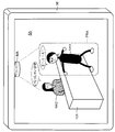
- FIG. 5 is a schematic diagram showing an image showing a situation in which a conversation between the receptionist hm2 and the customer hm1 is collected by the microphone array device MA installed at the store window.
- the imaging area SA captured by the camera device CA which is a fixed camera installed on the ceiling in the store is displayed on the display device 36.
- the microphone array device MA is installed directly above the counter 101 where the receptionist hm2 (an example of an employee) faces the customer hm1.
- the microphone array device MA picks up the voice in the store including the conversation between the receptionist hm2 and the customer hm1.
- the counter 101 where the customer hm1 is located is set in the privacy protection area PRA.
- the privacy protection area PRA is set by, for example, designating a range by a touch operation or the like with respect to an image previously displayed on the display device 36 by the user.
- FIG. 5 shows a situation where the customer hm1 has visited the store in the imaging area SA and is in the privacy protection area PRA installed in front of the counter 101. For example, when the receptionist hm2 greets “I welcome you”, the sound is output from the speaker device 37. In addition, for example, the customer hm1 is talking with a steep expression, but the voice is output from the speaker device 37 as a privacy sound.
- the user of the microphone array system 10 can detect the emotion of the customer hm1 from the change in the pitch of the privacy sound output from the speaker device 37.
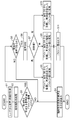
- FIG. 6 is a flowchart showing a procedure for outputting the sound collected by the microphone array apparatus MA. This voice output operation is performed, for example, after the voice data of the voice collected by the microphone array apparatus MA is temporarily stored in the recorder RC.
- the communication unit 31 acquires audio data and video data for a predetermined time recorded in the recorder RC via the network NW (S1).
- the directivity control unit 41 forms directivity with respect to the sound data collected by the microphone array apparatus MA, and acquires sound data having a predetermined direction in the store or the like as the direction of direction (S2).
- the privacy judgment unit 42 determines whether or not the voice position where the directivity is formed by the directivity control unit 41 is within the privacy protection area PRA (S3).
- the output control unit 35 When the voice position is not within the privacy protection area PRA, the output control unit 35 outputs the voice data with directivity formed to the speaker device 37 as it is (S4). In this case, the output control unit 35 outputs the video data to the display device 36. Thereafter, the signal processing unit 33 ends this operation.
- the utterance determination unit 34 determines whether or not the voice with the directivity formed is the voice of the utterance. (S5).
- the speech determination unit 34 is a voice in which directivity-formed voice is spoken by a person such as a conversation between the receptionist hm2 and the customer hm1, and is narrower than an audible frequency band (for example, 300 Hz-4 kHz). It is determined whether or not the sound has a frequency of
- the voice analysis unit 45 performs voice analysis on the voice data with the directivity formed (S6).
- the voice analysis unit 45 uses the emotion value table 47 registered in the privacy sound DB 48 to determine whether the emotion value of the uttered voice is “high”, “medium”, or “low”. Discriminate (S7).
- the privacy sound conversion unit 46 reads the sine wave sound data using the alternative sound table 49, and the sound of the high frequency (for example, 1 kHz). Data is converted (S8).
- the output control unit 35 outputs high-frequency audio data as a privacy sound to the speaker device 37 (S11).
- the speaker device 37 outputs a “beep sound” that is a privacy sound. Thereafter, the signal processing unit 33 ends this operation.
- the privacy sound conversion unit 46 reads out the sine wave sound data using the alternative sound table 49, and the sound of the middle frequency (for example, 500 Hz). Data is converted (S9).
- step S11 the output control unit 35 outputs the mid-frequency audio data to the speaker device 37 as a privacy sound.
- the speaker device 37 outputs a “beep sound” that is a privacy sound. Thereafter, the signal processing unit 33 ends this operation.
- the privacy sound conversion unit 46 reads out the sine wave sound data using the alternative sound table 49, and the sound of the low frequency (for example, 200 Hz). Data is converted (S10).
- step S11 the output control unit 35 outputs low-frequency audio data to the speaker device 37 as a privacy sound.
- the speaker device 37 outputs a “beep sound” that is a privacy sound. Thereafter, the signal processing unit 33 ends this operation.
- the microphone array system 10 for example, even if the user does not know the content of the utterance of the customer hm 1 output from the speaker device 37, the customer hm 1 is angry because of the pitch of the “pea” sound emitted as the privacy sound. I can sense emotions such as being.
- the user changes the emotion of the customer hm1 while the content of the utterance of the customer hm1 is concealed. Can understand.
- the voice processing device is configured to acquire a voice when the voice collected by the voice collecting unit, a detection unit that detects the voice position of the voice, and the voice position is within the privacy protection area PRA.
- a determination unit that determines whether or not a voice is an utterance, an analysis unit that analyzes an utterance voice and obtains an emotion value, a conversion unit that converts the utterance voice into an alternative sound corresponding to the emotion value,
- An output control unit 35 that outputs a substitute sound to the sound output unit that outputs sound is provided.
- the voice processing device is, for example, the directivity control device 30.
- the sound collection unit is, for example, a microphone array device MA.
- the acquisition unit is, for example, the communication unit 31.
- the detection unit is, for example, the directivity control unit 41.
- the determination unit is, for example, the utterance determination unit 34.
- the analysis unit is, for example, a voice analysis unit 45.
- the audio output unit is, for example, a speaker device 37.
- the conversion unit is, for example, a privacy sound conversion unit 46.
- the substitute sound is, for example, a privacy sound.
- the voice processing device can grasp the emotion of the speaker while protecting the privacy.
- the voice of the utterance can be concealed with the substitute sound, and the privacy protection of the customer hm1 is ensured.
- the voice processing device does not mask the spoken voice uniformly, but uses different substitute sounds according to the spoken voice, it can output substitute sounds according to the emotion of the speaker. Therefore, the user can also infer a change in the feelings of customer hm1 even if the conversation records of receptionist hm2 and customer hm1 are used as a trouble case for looking back when a complaint occurs or in-house training materials. That is, for example, the user can grasp how the customer hm1 settles when the employee hm2 responds to the customer hm1 at the time of trouble.
- the analysis unit may acquire at least one emotion value by analyzing at least one (including a plurality of combinations) of pitch change, speech speed, volume, and smooth tongue with respect to the speech voice.
- the conversion unit may change the frequency of the alternative sound according to the emotion value.
- the alternative sound corresponding to the emotion value obtained as a result of performing the voice analysis by the voice analysis unit 45 is output as the privacy sound.
- a face icon corresponding to an emotion value is output instead of an image of an audio position captured by the camera device CA.
- FIG. 7 is a block diagram showing the configuration of the microphone array system 10A in the second embodiment.
- the microphone array system of the second embodiment has almost the same configuration as that of the first embodiment.
- the description is abbreviate
- the microphone array system 10A includes a voice analysis unit 45A and a video conversion unit 65 in addition to the configuration similar to that of the microphone array system 10 of the first embodiment.
- the voice analysis unit 45A omits the privacy sound conversion unit 46 and has a privacy sound DB 48A.
- the voice analysis unit 45A receives the voice in the privacy protection area PRA picked up by the microphone array device MA, the voice analysis unit 45A analyzes the voice and acquires the emotion of the person who emitted the voice as an emotion value.
- an emotion value table 47 registered in the privacy sound DB 48A is used.
- the video conversion unit 65 includes a face icon conversion unit 66 and a face icon DB 68.
- the video conversion unit 65 converts the video at the audio position captured by the camera device CA into a substitute image (for example, a face icon) corresponding to the emotion value.
- a substitute image table 67 is stored in the face icon DB 68.
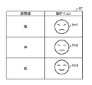
- FIG. 8 is a schematic diagram showing the registration contents of the alternative image table 67.
- face icons fm (fm1, fm2, fm3,%) Corresponding to emotion values are registered. For example, when the emotion value is high and “high”, it is converted into a face icon fm1 having an angry expression. For example, when the emotion value is normal (medium) and “medium”, it is converted into a face icon fm2 having a gentle expression. For example, when the emotion value is low and “low”, it is converted into a face icon fm3 having a smiling expression.
- FIG. 8 shows three registration examples, any number of face icons may be registered so as to correspond to emotion values.
- the face icon conversion unit 66 acquires the face icon fm corresponding to the emotion value obtained as a result of the voice analysis by the voice analysis unit 45A from the substitute image table 67 in the face icon DB 68.
- the face icon conversion unit 66 superimposes the acquired face icon fm on the audio position image captured by the camera device CA.
- the video conversion unit 65 sends the image data after the face icon conversion to the output control unit 35.
- the output control unit 35 causes the display device 36 to display the image data after the face icon conversion.
- FIG. 9 is a schematic diagram showing an image showing a situation in which a conversation between the receptionist hm2 and the customer hm1 is collected by the microphone array device MA installed at the store window.
- an imaging area SA captured by the camera device CA which is a fixed camera installed on the ceiling in the store, is displayed on the display device 36.
- the microphone array device MA is installed just above the counter 101 where the receptionist hm2 faces the customer hm1.
- the microphone array device MA picks up the voice in the store including the conversation between the receptionist hm2 and the customer hm1.
- the counter 101 where the customer hm1 is located is set in the privacy protection area PRA.
- the privacy protection area PRA is set by, for example, designating a range by a touch operation or the like with respect to an image previously displayed on the display device 36 by the user.
- the video in FIG. 9 shows a situation in which the customer hm1 comes to the store in the imaging area SA and enters the privacy protection area PRA installed in front of the counter 101. For example, when the receptionist hm2 greets “I welcome you”, the sound is output from the speaker device 37. Further, for example, the voice uttered by the customer hm1 is output from the speaker device 37 as “the case of the other day's trouble”. Pronunciation content is recognizable.
- a face icon fm1 having an angry expression is drawn near the face (voice position) of the customer hm1 standing in the privacy protection area PRA.
- the user can detect the utterance content and can detect the emotion of the customer hm1 from the face icon fm1.
- the face of the customer hm1 is concealed (masked) by the face icon fm1, and the privacy protection of the customer hm1 is ensured.
- FIG. 10 is a flowchart showing a video output procedure including a face icon based on the sound collected by the microphone array apparatus MA. This video output operation is performed, for example, after the sound data and image data of the sound collected by the microphone array device MA are temporarily stored in the recorder RC.
- the output control unit 35 outputs video data including a face image captured by the camera device CA to the display device 36 (S4A). In this case, the output control unit 35 outputs the voice data with directivity formed to the speaker device 37 as it is. Thereafter, the signal processing unit 33 ends this operation.
- the face icon conversion unit 66 reads the face icon fm1 corresponding to the emotion value “high” registered in the alternative image table 67.
- the face icon conversion unit 66 converts the video data by superimposing the read face icon fm1 on the face image (audio position) of the video data captured by the camera device CA (S8A).
- the face icon conversion unit 66 may convert the video data by replacing the face image (sound position) of the video data captured by the camera device CA with the read face icon fm1 (S8A). ).
- the output control unit 35 outputs the converted video data to the display device 36 (S11A).
- the display device 36 displays video data including the face icon fm1.
- the output control unit 35 outputs the sound data with directivity formed to the speaker device 37 as it is. Thereafter, the signal processing unit 33 ends this operation.
- the face icon conversion unit 66 reads the face icon fm2 registered in the substitute image table 67 and corresponding to the emotion value “medium”.
- the face icon conversion unit 66 converts the video data by superimposing the read face icon fm2 on the face image (sound position) of the video data captured by the camera device CA (S9A).
- the face icon conversion unit 66 may convert the video data by replacing the face image (sound position) of the video data captured by the camera device CA with the read face icon fm2 (S9A). ).
- the output control unit 35 outputs the converted video data to the display device 36 in S11A.
- the display device 36 displays video data including the face icon fm2.
- the output control unit 35 outputs the sound data with directivity formed to the speaker device 37 as it is. Thereafter, the signal processing unit 33 ends this operation.
- the face icon conversion unit 66 reads the face icon fm3 corresponding to the emotion value “low” registered in the alternative image table 67.
- the face icon conversion unit 66 converts the video data by superimposing the read face icon fm3 on the face image (audio position) of the video data captured by the camera device CA (S10A).
- the face icon conversion unit 66 may convert the video data by replacing the face image (audio position) of the video data captured by the camera device CA with the read face icon fm3 (S10A). ).
- the output control unit 35 outputs the converted video data to the display device 36 in S11A.
- the display device 36 displays video data including the face icon fm3.
- the output control unit 35 outputs the sound data with directivity formed to the speaker device 37 as it is. Thereafter, the signal processing unit 33 ends this operation.
- the microphone array system 10A for example, even if it is difficult for the user to visually recognize the face image of the customer hm1 displayed on the display device 36, the user hm1 is angry based on the type of the displayed face icon fm. Can be observed.
- the user can change the emotion of the customer hm1 while the face image of the customer hm1 is concealed. Understandable.
- the acquisition unit acquires the video of the imaging area SA captured by the imaging unit, and acquires the audio of the imaging area SA collected by the sound collection unit.
- the conversion unit converts the video at the audio position into an alternative image corresponding to the emotion value.
- the output control unit 35 displays the substitute image on the display unit that displays the video.
- the imaging unit is, for example, a camera device CA.
- the conversion unit is, for example, a face icon conversion unit 66.
- the substitute image is, for example, a face icon fm.
- the display unit is, for example, the display device 36.
- the image processing apparatus detects the image of the imaging area SA captured by the imaging unit, the acquisition unit that acquires the sound of the imaging area SA collected by the sound collection unit, and the audio position of the audio
- a determination unit that determines whether or not the voice is an utterance when the voice position is within the privacy protection area PRA, and an analysis unit that analyzes the utterance and acquires an emotion value
- a conversion unit that converts the video at the audio position into a substitute image corresponding to the emotion value
- an output control unit 35 that displays the substitute image on the display unit that displays the video.
- the image processing apparatus is, for example, the directivity control apparatus 30.
- the user can detect the emotion of the customer hm1 from the face icon fm. Further, the face icon of the customer hm1 can be concealed (masked) by the face icon, and the privacy protection of the customer hm1 is ensured. Therefore, the voice processing device can visually grasp the emotion of the speaker while protecting the privacy.
- the conversion unit may display different alternative images indicating emotions according to emotion values.
- the speech processing apparatus can output a face icon fm or the like having a different expression depending on the emotion value. Therefore, the user can appropriately grasp the emotion of the customer hm1.
- FIG. 11 is a block diagram showing a configuration of a microphone array system 10B in the third embodiment.
- the description is abbreviate
- the microphone array system 10B has a configuration similar to that of the first and second embodiments, and includes both the audio analysis unit 45 and the video conversion unit 65.
- the configurations and operations of the audio analysis unit 45 and the video conversion unit 65 are as described above.
- a conversation between a customer who visits a store and a receptionist is collected and output as a voice, and an imaging area where the customer and the receptionist are located Suppose that is recorded.
- FIG. 12 is a schematic diagram showing an image representing a situation in which a conversation between the receptionist hm2 and the customer hm1 is collected by the microphone array device MA installed at the store window.
- the video displayed on the display device 36 shown in FIG. 12 shows a situation where the customer hm1 has visited the store and is in the privacy protection area PRA installed in front of the counter 101. For example, when the receptionist hm2 greets “I welcome you”, the sound is output from the speaker device 37. In addition, for example, the customer hm1 also speaks to the receptionist hm2, but the speaker device 37 outputs “Peep, Peep, Peep” and a privacy sound.
- the user of the microphone array system 10B can detect the emotion of the customer hm1 from the change in the pitch of the privacy sound output from the speaker device 37.
- a face icon fm1 having an angry expression is placed near the face (speech position) of the customer hm1 standing in the privacy protection area PRA.
- the user can detect the emotion of the customer hm1 from the face icon fm1. Further, the face icon fm1 conceals (masks) the customer hm1's face, thereby protecting the privacy of the customer hm1.
- the microphone array system 10B detects an image capturing unit that captures an image of the image capturing area SA, a sound collecting unit that collects sound in the image capturing area, and a voice position of the sound collected by the sound collecting unit.
- a detection unit a determination unit that determines whether or not the voice is an utterance voice when the voice position is within the privacy protection area PRA, an analysis unit that analyzes an utterance voice and obtains an emotion value;
- a conversion unit that performs a conversion process corresponding to the emotion value and an output control unit 35 that outputs the result of the conversion process are provided.
- the conversion process includes, for example, at least one of an audio process for converting to a privacy sound and an image conversion process for converting to a face icon fm.
- the microphone array system 10B can further protect the privacy because the utterance content of the customer hm1 is concealed by the privacy sound and the face of the customer hm1 is concealed by the face icon fm. At least one of the concealment of the speech content and the concealment of the face is performed. Further, the user can more easily detect the emotion of the customer hm1 by changing the pitch of the privacy sound and the type of the face icon.
- the sound detected in the imaging area SA is converted into a privacy sound without depending on the user. It was shown that the process to convert. Instead of this, the conversion process into the privacy sound may be performed depending on the user. The same applies to the conversion process of the face icon as well as the conversion process to the privacy sound.
- the conversion process to privacy sound is performed, and when the user is an authorized user such as an administrator, the conversion process to privacy sound is not performed. Also good. Which user is the user may be determined based on, for example, a user ID when logging into the directivity control device 30.
- the privacy sound conversion unit 46 performs a voice change process (processing process) on the sound data of the sound collected by the microphone array device MA as a privacy sound corresponding to the emotion value. You may give it.
- the privacy sound conversion unit 46 may change the frequency (pitch) of the voice data of the voice collected by the microphone array device MA, for example. That is, the privacy sound conversion unit 46 may change the frequency of the sound output from the speaker device 37 to another frequency that makes it difficult to understand the content of the sound.
- the output control unit 35 may cause the speaker device 37 to output the sound collected and processed by the microphone array device MA.
- the privacy of the subject for example, a person
- PRA privacy protection area
- the output control unit 35 indicates that the privacy protection area PRA includes an audio position corresponding to the designated position designated on the screen by the user's finger or stylus pen. You may explicitly notify the user.
- the privacy determination unit 42 may determine whether or not the collected time zone is included in a time zone requiring privacy protection (privacy protection time).
- the privacy sound conversion unit 46 and the face icon conversion unit 66 may convert at least a part of the voice or video according to the emotion value.
- the customer hm1 is set in the privacy protection area PRA, and at least a part of the voice or video is replaced with another voice or video depending on the emotion value detected from the utterance of the customer hm1.
- the receptionist hm2 is set as a privacy protection area, and at least a part of the voice or video is replaced according to the emotion value detected from the utterance of the receptionist hm2. It may be converted into another audio, video or image.
- the utterances of the customer hm1 and the receptionist hm2 are collected using the microphone array device MA and the directivity control device 30, but instead, the customer hm1 and the receptionist hm2 respectively.
- Each utterance may be picked up using a plurality of microphones (for example, directional microphones) installed in the vicinity of.
- the present disclosure is useful for a voice processing device, an image processing device, a microphone array system, a voice processing method, and the like that can detect the emotion of a speaker while protecting privacy.
Landscapes
- Engineering & Computer Science (AREA)
- Health & Medical Sciences (AREA)
- Acoustics & Sound (AREA)
- Signal Processing (AREA)
- Physics & Mathematics (AREA)
- Computational Linguistics (AREA)
- Audiology, Speech & Language Pathology (AREA)
- Human Computer Interaction (AREA)
- Quality & Reliability (AREA)
- Multimedia (AREA)
- General Health & Medical Sciences (AREA)
- Otolaryngology (AREA)
- Child & Adolescent Psychology (AREA)
- Hospice & Palliative Care (AREA)
- Psychiatry (AREA)
- Circuit For Audible Band Transducer (AREA)
- Obtaining Desirable Characteristics In Audible-Bandwidth Transducers (AREA)
- Soundproofing, Sound Blocking, And Sound Damping (AREA)
- User Interface Of Digital Computer (AREA)
Abstract
Priority Applications (4)
| Application Number | Priority Date | Filing Date | Title |
|---|---|---|---|
| JP2018502976A JP6887102B2 (ja) | 2016-02-29 | 2017-02-08 | 音声処理装置、画像処理装置、マイクアレイシステム、及び音声処理方法 |
| US16/074,311 US10943596B2 (en) | 2016-02-29 | 2017-02-08 | Audio processing device, image processing device, microphone array system, and audio processing method |
| EP17759574.1A EP3425635A4 (fr) | 2016-02-29 | 2017-02-08 | Dispositif de traitement audio, dispositif de traitement d'image, système de réseau de microphones et procédé de traitement audio |
| US17/168,450 US20210158828A1 (en) | 2016-02-29 | 2021-02-05 | Audio processing device, image processing device, microphone array system, and audio processing method |
Applications Claiming Priority (2)
| Application Number | Priority Date | Filing Date | Title |
|---|---|---|---|
| JP2016-038227 | 2016-02-29 | ||
| JP2016038227 | 2016-02-29 |
Related Child Applications (2)
| Application Number | Title | Priority Date | Filing Date |
|---|---|---|---|
| US16/074,311 A-371-Of-International US10943596B2 (en) | 2016-02-29 | 2017-02-08 | Audio processing device, image processing device, microphone array system, and audio processing method |
| US17/168,450 Continuation US20210158828A1 (en) | 2016-02-29 | 2021-02-05 | Audio processing device, image processing device, microphone array system, and audio processing method |
Publications (1)
| Publication Number | Publication Date |
|---|---|
| WO2017150103A1 true WO2017150103A1 (fr) | 2017-09-08 |
Family
ID=59743795
Family Applications (1)
| Application Number | Title | Priority Date | Filing Date |
|---|---|---|---|
| PCT/JP2017/004483 Ceased WO2017150103A1 (fr) | 2016-02-29 | 2017-02-08 | Dispositif de traitement audio, dispositif de traitement d'image, système de réseau de microphones et procédé de traitement audio |
Country Status (4)
| Country | Link |
|---|---|
| US (2) | US10943596B2 (fr) |
| EP (1) | EP3425635A4 (fr) |
| JP (1) | JP6887102B2 (fr) |
| WO (1) | WO2017150103A1 (fr) |
Cited By (6)
| Publication number | Priority date | Publication date | Assignee | Title |
|---|---|---|---|---|
| JP2020052775A (ja) * | 2018-09-27 | 2020-04-02 | 株式会社コロプラ | プログラム、仮想空間の提供方法および情報処理装置 |
| US20200388283A1 (en) * | 2019-06-06 | 2020-12-10 | Beijing Baidu Netcom Science And Technology Co., Ltd. | Method and apparatus for processing speech |
| JP2021033573A (ja) * | 2019-08-22 | 2021-03-01 | ソニー株式会社 | 情報処理装置、情報処理方法、およびプログラム |
| JP2021149664A (ja) * | 2020-03-19 | 2021-09-27 | ヤフー株式会社 | 出力装置、出力方法及び出力プログラム |
| JP2022041858A (ja) * | 2020-08-31 | 2022-03-11 | テイ・エス テック株式会社 | 車内システム |
| JP2025100673A (ja) * | 2021-12-16 | 2025-07-03 | 日本電気株式会社 | システム、サーバ装置、サーバ装置の制御方法及びプログラム |
Families Citing this family (4)
| Publication number | Priority date | Publication date | Assignee | Title |
|---|---|---|---|---|
| US11527265B2 (en) * | 2018-11-02 | 2022-12-13 | BriefCam Ltd. | Method and system for automatic object-aware video or audio redaction |
| CN111833418B (zh) * | 2020-07-14 | 2024-03-29 | 北京百度网讯科技有限公司 | 动画交互方法、装置、设备以及存储介质 |
| US20220293122A1 (en) * | 2021-03-15 | 2022-09-15 | Avaya Management L.P. | System and method for content focused conversation |
| CN113571097B (zh) * | 2021-09-28 | 2022-01-18 | 之江实验室 | 一种说话人自适应的多视角对话情感识别方法及系统 |
Citations (7)
| Publication number | Priority date | Publication date | Assignee | Title |
|---|---|---|---|---|
| JP2003248837A (ja) * | 2001-11-12 | 2003-09-05 | Mega Chips Corp | 画像作成装置、画像作成システム、音声生成装置、音声生成システム、画像作成用サーバ、プログラム、および記録媒体 |
| JP2004248145A (ja) * | 2003-02-17 | 2004-09-02 | Megachips System Solutions Inc | 多地点通信システム |
| JP2010169925A (ja) * | 2009-01-23 | 2010-08-05 | Konami Digital Entertainment Co Ltd | 音声処理装置、チャットシステム、音声処理方法、ならびに、プログラム |
| JP2011002704A (ja) * | 2009-06-19 | 2011-01-06 | Nippon Telegr & Teleph Corp <Ntt> | 音響信号送信装置、音響信号受信装置、音響信号送信方法及びそのプログラム |
| JP2014143678A (ja) | 2012-12-27 | 2014-08-07 | Panasonic Corp | 音声処理システム及び音声処理方法 |
| WO2014192457A1 (fr) * | 2013-05-30 | 2014-12-04 | ソニー株式会社 | Dispositif client, procédé, système et programme de commande |
| JP2015029241A (ja) | 2013-06-24 | 2015-02-12 | パナソニックIpマネジメント株式会社 | 指向性制御システム及び音声出力制御方法 |
Family Cites Families (11)
| Publication number | Priority date | Publication date | Assignee | Title |
|---|---|---|---|---|
| US5567901A (en) * | 1995-01-18 | 1996-10-22 | Ivl Technologies Ltd. | Method and apparatus for changing the timbre and/or pitch of audio signals |
| US6095650A (en) * | 1998-09-22 | 2000-08-01 | Virtual Visual Devices, Llc | Interactive eyewear selection system |
| JP2001036544A (ja) * | 1999-07-23 | 2001-02-09 | Sharp Corp | 通信ネットワークの擬人化処理装置および擬人化処理方法 |
| JP4169712B2 (ja) * | 2004-03-03 | 2008-10-22 | 久徳 伊藤 | 会話支援システム |
| JP4871552B2 (ja) * | 2004-09-10 | 2012-02-08 | パナソニック株式会社 | 情報処理端末 |
| CN1815550A (zh) * | 2005-02-01 | 2006-08-09 | 松下电器产业株式会社 | 可识别环境中的语音与非语音的方法及系统 |
| US8046220B2 (en) * | 2007-11-28 | 2011-10-25 | Nuance Communications, Inc. | Systems and methods to index and search voice sites |
| KR101558553B1 (ko) * | 2009-02-18 | 2015-10-08 | 삼성전자 주식회사 | 아바타 얼굴 표정 제어장치 |
| US8525885B2 (en) * | 2011-05-15 | 2013-09-03 | Videoq, Inc. | Systems and methods for metering audio and video delays |
| US20140006017A1 (en) * | 2012-06-29 | 2014-01-02 | Qualcomm Incorporated | Systems, methods, apparatus, and computer-readable media for generating obfuscated speech signal |
| JP6985005B2 (ja) * | 2015-10-14 | 2021-12-22 | パナソニック インテレクチュアル プロパティ コーポレーション オブ アメリカPanasonic Intellectual Property Corporation of America | 感情推定方法、感情推定装置、及び、プログラムを記録した記録媒体 |
-
2017
- 2017-02-08 JP JP2018502976A patent/JP6887102B2/ja active Active
- 2017-02-08 US US16/074,311 patent/US10943596B2/en active Active
- 2017-02-08 WO PCT/JP2017/004483 patent/WO2017150103A1/fr not_active Ceased
- 2017-02-08 EP EP17759574.1A patent/EP3425635A4/fr not_active Withdrawn
-
2021
- 2021-02-05 US US17/168,450 patent/US20210158828A1/en not_active Abandoned
Patent Citations (7)
| Publication number | Priority date | Publication date | Assignee | Title |
|---|---|---|---|---|
| JP2003248837A (ja) * | 2001-11-12 | 2003-09-05 | Mega Chips Corp | 画像作成装置、画像作成システム、音声生成装置、音声生成システム、画像作成用サーバ、プログラム、および記録媒体 |
| JP2004248145A (ja) * | 2003-02-17 | 2004-09-02 | Megachips System Solutions Inc | 多地点通信システム |
| JP2010169925A (ja) * | 2009-01-23 | 2010-08-05 | Konami Digital Entertainment Co Ltd | 音声処理装置、チャットシステム、音声処理方法、ならびに、プログラム |
| JP2011002704A (ja) * | 2009-06-19 | 2011-01-06 | Nippon Telegr & Teleph Corp <Ntt> | 音響信号送信装置、音響信号受信装置、音響信号送信方法及びそのプログラム |
| JP2014143678A (ja) | 2012-12-27 | 2014-08-07 | Panasonic Corp | 音声処理システム及び音声処理方法 |
| WO2014192457A1 (fr) * | 2013-05-30 | 2014-12-04 | ソニー株式会社 | Dispositif client, procédé, système et programme de commande |
| JP2015029241A (ja) | 2013-06-24 | 2015-02-12 | パナソニックIpマネジメント株式会社 | 指向性制御システム及び音声出力制御方法 |
Non-Patent Citations (2)
| Title |
|---|
| See also references of EP3425635A4 |
| TAKANOBU NISHIURA ET AL.: "Multiple sound source location estimation based on CSP method using microphone array", TRANSACTIONS OF THE INSTITUTE OF ELECTRONICS, INFORMATION AND COMMUNICATION ENGINEERS, D - 11, vol. J83-D-11, no. 8, August 2000 (2000-08-01), pages 1713 - 1721 |
Cited By (11)
| Publication number | Priority date | Publication date | Assignee | Title |
|---|---|---|---|---|
| JP2020052775A (ja) * | 2018-09-27 | 2020-04-02 | 株式会社コロプラ | プログラム、仮想空間の提供方法および情報処理装置 |
| US20200388283A1 (en) * | 2019-06-06 | 2020-12-10 | Beijing Baidu Netcom Science And Technology Co., Ltd. | Method and apparatus for processing speech |
| US11488603B2 (en) * | 2019-06-06 | 2022-11-01 | Beijing Baidu Netcom Science And Technology Co., Ltd. | Method and apparatus for processing speech |
| JP2021033573A (ja) * | 2019-08-22 | 2021-03-01 | ソニー株式会社 | 情報処理装置、情報処理方法、およびプログラム |
| JP7334536B2 (ja) | 2019-08-22 | 2023-08-29 | ソニーグループ株式会社 | 情報処理装置、情報処理方法、およびプログラム |
| US12272090B2 (en) | 2019-08-22 | 2025-04-08 | Sony Group Corporation | Information processing apparatus, and information processing method |
| JP2021149664A (ja) * | 2020-03-19 | 2021-09-27 | ヤフー株式会社 | 出力装置、出力方法及び出力プログラム |
| JP7248615B2 (ja) | 2020-03-19 | 2023-03-29 | ヤフー株式会社 | 出力装置、出力方法及び出力プログラム |
| JP2022041858A (ja) * | 2020-08-31 | 2022-03-11 | テイ・エス テック株式会社 | 車内システム |
| JP7656178B2 (ja) | 2020-08-31 | 2025-04-03 | テイ・エス テック株式会社 | 車内システム |
| JP2025100673A (ja) * | 2021-12-16 | 2025-07-03 | 日本電気株式会社 | システム、サーバ装置、サーバ装置の制御方法及びプログラム |
Also Published As
| Publication number | Publication date |
|---|---|
| US20210158828A1 (en) | 2021-05-27 |
| EP3425635A4 (fr) | 2019-03-27 |
| JP6887102B2 (ja) | 2021-06-16 |
| JPWO2017150103A1 (ja) | 2019-01-31 |
| EP3425635A1 (fr) | 2019-01-09 |
| US20200152215A1 (en) | 2020-05-14 |
| US10943596B2 (en) | 2021-03-09 |
Similar Documents
| Publication | Publication Date | Title |
|---|---|---|
| JP6887102B2 (ja) | 音声処理装置、画像処理装置、マイクアレイシステム、及び音声処理方法 | |
| US11531518B2 (en) | System and method for differentially locating and modifying audio sources | |
| JP6135880B2 (ja) | 音声処理方法、音声処理システム、及び記憶媒体 | |
| US10497356B2 (en) | Directionality control system and sound output control method | |
| JP5452158B2 (ja) | 音響監視システム、及び音声集音システム | |
| JP5857674B2 (ja) | 画像処理装置、及び画像処理システム | |
| US20230177942A1 (en) | Systems and methods for identifying an acoustic source based on observed sound | |
| CN108762494A (zh) | 显示信息的方法、装置及存储介质 | |
| JP6447976B2 (ja) | 指向性制御システム及び音声出力制御方法 | |
| WO2017134300A1 (fr) | Procédé d'aide au suivi d'une conversation pour personne malentendante | |
| CN111933174A (zh) | 语音处理方法、装置、设备和系统 | |
| CN106782625B (zh) | 音频处理方法和装置 | |
| JPWO2015151130A1 (ja) | 音声処理方法、音声処理システム、及び記憶媒体 | |
| KR101976937B1 (ko) | 마이크로폰 어레이를 이용한 회의록 자동작성장치 | |
| EP3149968B1 (fr) | Procédé d'aide au suivi d'une conversation pour personne malentendante | |
| JP6569853B2 (ja) | 指向性制御システム及び音声出力制御方法 | |
| CN113038338A (zh) | 降噪处理方法和装置 | |
| JP2016219966A (ja) | 指向性制御システム及び音声出力制御方法 | |
| JP2016219965A (ja) | 指向性制御システム及び音声出力制御方法 | |
| EP2927885A1 (fr) | Appareil de traitement du son, système de traitement sonore et procédé de traitement sonore |
Legal Events
| Date | Code | Title | Description |
|---|---|---|---|
| WWE | Wipo information: entry into national phase |
Ref document number: 2018502976 Country of ref document: JP |
|
| NENP | Non-entry into the national phase |
Ref country code: DE |
|
| WWE | Wipo information: entry into national phase |
Ref document number: 2017759574 Country of ref document: EP |
|
| ENP | Entry into the national phase |
Ref document number: 2017759574 Country of ref document: EP Effective date: 20181001 |
|
| 121 | Ep: the epo has been informed by wipo that ep was designated in this application |
Ref document number: 17759574 Country of ref document: EP Kind code of ref document: A1 |