WO2017150196A1 - Procédé de fabrication d'un objet moulé tridimensionnel, objet moulé tridimensionnel et dispositif de moulage - Google Patents
Procédé de fabrication d'un objet moulé tridimensionnel, objet moulé tridimensionnel et dispositif de moulage Download PDFInfo
- Publication number
- WO2017150196A1 WO2017150196A1 PCT/JP2017/005652 JP2017005652W WO2017150196A1 WO 2017150196 A1 WO2017150196 A1 WO 2017150196A1 JP 2017005652 W JP2017005652 W JP 2017005652W WO 2017150196 A1 WO2017150196 A1 WO 2017150196A1
- Authority
- WO
- WIPO (PCT)
- Prior art keywords
- modeling
- dimensional structure
- support member
- reinforcing material
- surrounding
- Prior art date
- Legal status (The legal status is an assumption and is not a legal conclusion. Google has not performed a legal analysis and makes no representation as to the accuracy of the status listed.)
- Ceased
Links
Images


Classifications
-
- B—PERFORMING OPERATIONS; TRANSPORTING
- B29—WORKING OF PLASTICS; WORKING OF SUBSTANCES IN A PLASTIC STATE IN GENERAL
- B29C—SHAPING OR JOINING OF PLASTICS; SHAPING OF MATERIAL IN A PLASTIC STATE, NOT OTHERWISE PROVIDED FOR; AFTER-TREATMENT OF THE SHAPED PRODUCTS, e.g. REPAIRING
- B29C67/00—Shaping techniques not covered by groups B29C39/00 - B29C65/00, B29C70/00 or B29C73/00
-
- B—PERFORMING OPERATIONS; TRANSPORTING
- B33—ADDITIVE MANUFACTURING TECHNOLOGY
- B33Y—ADDITIVE MANUFACTURING, i.e. MANUFACTURING OF THREE-DIMENSIONAL [3D] OBJECTS BY ADDITIVE DEPOSITION, ADDITIVE AGGLOMERATION OR ADDITIVE LAYERING, e.g. BY 3D PRINTING, STEREOLITHOGRAPHY OR SELECTIVE LASER SINTERING
- B33Y10/00—Processes of additive manufacturing
-
- B—PERFORMING OPERATIONS; TRANSPORTING
- B33—ADDITIVE MANUFACTURING TECHNOLOGY
- B33Y—ADDITIVE MANUFACTURING, i.e. MANUFACTURING OF THREE-DIMENSIONAL [3D] OBJECTS BY ADDITIVE DEPOSITION, ADDITIVE AGGLOMERATION OR ADDITIVE LAYERING, e.g. BY 3D PRINTING, STEREOLITHOGRAPHY OR SELECTIVE LASER SINTERING
- B33Y30/00—Apparatus for additive manufacturing; Details thereof or accessories therefor
-
- B—PERFORMING OPERATIONS; TRANSPORTING
- B33—ADDITIVE MANUFACTURING TECHNOLOGY
- B33Y—ADDITIVE MANUFACTURING, i.e. MANUFACTURING OF THREE-DIMENSIONAL [3D] OBJECTS BY ADDITIVE DEPOSITION, ADDITIVE AGGLOMERATION OR ADDITIVE LAYERING, e.g. BY 3D PRINTING, STEREOLITHOGRAPHY OR SELECTIVE LASER SINTERING
- B33Y80/00—Products made by additive manufacturing
Definitions
- the present invention relates to a three-dimensional structure manufacturing method, a three-dimensional structure, and a modeling apparatus that manufacture a three-dimensional structure by discharging a liquid modeling material and then solidifying the discharged modeling material.
- Patent Document 1 a method of manufacturing a three-dimensional structure by discharging a liquid modeling material and then solidifying the discharged modeling material is known (see Patent Document 1).
- the thin part of the three-dimensional structure supports a part of the three-dimensional structure.
- the weight of the part supported by the thin part of the three-dimensional structure, or the thin part of the three-dimensional structure by an external force applied by a human hand to the part supported by the thin part of the three-dimensional structure Since stress is concentrated on the three-dimensional structure, there is a problem that breakage may occur in a thin portion of the three-dimensional structure.
- a modeling material that is solid and highly flexible is used to prevent breakage, the weight of the part supported by the thin part of the three-dimensional structure and the thin part of the three-dimensional structure are supported.
- the thin part of the three-dimensional structure is bent by the external force applied by the hand of the person to the part that is applied, and the thin part of the three-dimensional structure appropriately supports a part of the three-dimensional structure.
- Such thin parts include human feet, animal feet, insect feet, dragonfly wings, plant leaves and branches.
- the three-dimensional structure manufacturing method of the present invention is a three-dimensional structure manufacturing method for manufacturing a three-dimensional structure by discharging a liquid modeling material and then solidifying the discharged modeling material.
- the modeling material that forms the internal part by a process has a higher rigidity in a solid state than the modeling material that forms the peripheral part by the perimeter forming process.
- the three-dimensional structure manufactured by the three-dimensional structure manufacturing method of the present invention has a solid state rigidity in which the modeling material forming the inner part forms a surrounding part. Since it is large, the rigidity in a thin part can be improved by the modeling material which forms an internal part. Therefore, the three-dimensional structure manufacturing method of the present invention can manufacture a three-dimensional structure that can suppress the occurrence of breakage and bending in a thin portion. Moreover, since the internal part is formed by putting the liquid modeling material into a groove
- the internal forming step and the surrounding forming step may be a step of discharging the liquid forming material by an ink jet method.
- the three-dimensional structure manufacturing method of the present invention forms both the inner part and the surrounding part by the ink jet method, so that the three-dimensional structure can be easily manufactured.
- the three-dimensional structure manufacturing method of the present invention is a three-dimensional structure manufacturing method for manufacturing a three-dimensional structure by discharging a liquid modeling material and then solidifying the discharged modeling material.
- the reinforcing material has a higher rigidity than the solid modeling material.
- the three-dimensional structure manufactured by the method of manufacturing a three-dimensional structure of the present invention has higher rigidity than a solid-state modeling material in which a reinforcing material that forms an internal portion forms a surrounding portion. Therefore, the rigidity in the thin part can be improved by the reinforcing material. Therefore, the three-dimensional structure manufacturing method of the present invention can manufacture a three-dimensional structure that can suppress the occurrence of breakage and bending in a thin portion.
- the reinforcing material may include a connecting portion for connecting to another member.
- the three-dimensional structure manufactured by the three-dimensional structure manufacturing method of the present invention can improve convenience because the reinforcing material is used for connection to other members in addition to reinforcement. .
- the internal forming step includes the step of forming the reinforcing material in the inner portion before the peripheral portion of the three-dimensional structure is formed by the peripheral forming step. It may be a process to be arranged.
- the three-dimensional structure manufacturing method of the present invention has a three-dimensional structure compared to a method in which a reinforcing material is inserted into the peripheral portion after all the peripheral portions of the three-dimensional structure are formed. It is possible to easily fix the reinforcing material in the interior.
- the surrounding forming step is a step of discharging the liquid forming material by a forming apparatus based on modeling data, and the surrounding forming step is performed by the internal forming step. After the reinforcing material is disposed in the portion, the position of the reinforcing material relative to the surrounding portion may be detected, and the modeling data may be corrected based on the detected position.
- the three-dimensional structure manufacturing method according to the present invention corrects the modeling data based on the position of the reinforcing material with respect to the surrounding portion, and therefore can facilitate the work of arranging the reinforcing material on the surrounding portion. . Therefore, the three-dimensional structure manufacturing method of the present invention can facilitate the manufacture of the three-dimensional structure.
- the reinforcing material is inserted into the internal portion after all the peripheral portions of the three-dimensional structure are formed by the peripheral formation step. It may be a process.
- the three-dimensional structure manufacturing method of the present invention is more effective than the method in which the reinforcing material is disposed in the surrounding portion before the surrounding portion of the part of the three-dimensional structure is formed.
- the manufacture of the part can be facilitated.
- the surrounding formation step is a step in which a direction orthogonal to the extending direction of the layer is a vertical direction, and the three-dimensional structure is a vertical direction in the periphery forming step.
- a space is formed in a part of the lower portion of the reinforcing material in the space, and the surrounding portion supports the reinforcing material on the lower side of the reinforcing material in the vertical direction in the surrounding forming step.
- the surface of the support portion may be an inclined surface that does not overhang in the periphery forming step.
- the three-dimensional structure manufacturing method according to the present invention is configured so that the space in which the modeling material does not exist is formed in a part of the portion that becomes the lower side of the reinforcing material in the vertical direction in the periphery forming process. Since the amount of the material is greatly reduced, it is possible to reduce the weight of the three-dimensional structure and the material cost. Further, in the three-dimensional structure manufacturing method of the present invention, since the surface of the support portion among the surfaces forming the space is an inclined surface that does not overhang in the surrounding formation step, the shape of each layer collapses in the space portion. As a result, the three-dimensional structure can be formed with high accuracy.
- the support portion includes an end support portion that supports the reinforcing material at an end portion of the reinforcing material in the extending direction of the layer, and a portion other than the end portion. You may provide the non-end part support part which supports a reinforcing material.
- the three-dimensional structure manufacturing method of the present invention causes the reinforcing material to bend by providing the non-end support portion with the forming material at a portion of the reinforcing material having a long length in the extending direction of the layer. Therefore, it is possible to form a three-dimensional structure with high accuracy.
- the reinforcing member may have a hole formed in at least a part of a portion where the space is formed on both sides in a direction orthogonal to the extending direction of the layer. .
- the three-dimensional structure manufacturing method of the present invention significantly reduces the amount of necessary reinforcing material by forming holes in the reinforcing material. Can be reduced.
- the three-dimensional structure of the present invention includes an internal portion and a portion around the internal portion, and the peripheral portion is formed of a solid modeling material, and the internal portion is the modeling material.
- the reinforcing material is characterized in that it has higher rigidity than the solid modeling material.
- the three-dimensional structure of the present invention has a rigidity higher than that of a solid-state modeling material in which the reinforcing material forming the inner part forms a surrounding part. Can be improved. Therefore, the three-dimensional structure of the present invention can suppress the occurrence of breakage and bending at a thin portion.
- the reinforcing material may include a connection portion for connecting to another member.
- the three-dimensional structure of the present invention can improve convenience because the reinforcing material is used for connection to other members in addition to reinforcement.
- the three-dimensional structure of the present invention includes a plurality of porous sheets each having a plurality of holes formed therein and laminated, and a modeling material that bonds the porous sheets by entering the holes. To do.
- the three-dimensional structure of the present invention improves the mechanical strength by adhering the porous sheets to each other with a modeling material, so that the three-dimensional structure can suppress the occurrence of breakage and bending in a thin portion.
- the modeling material may be an ultraviolet curable ink that is cured by being irradiated with ultraviolet rays.
- the three-dimensional structure of the present invention can be manufactured at high speed and with high accuracy because the modeling material is cured at high speed with high accuracy.
- the modeling apparatus includes a support member on which a plurality of perforated sheets each having a large number of holes are stacked, and a modeling material that adheres the perforated sheets to each other by entering the holes. And a modeling material head for discharging toward the plurality of porous sheets.
- the modeling apparatus of the present invention improves the mechanical strength by adhering the porous sheets to each other with a modeling material, so that a three-dimensional structure with high mechanical strength can be manufactured. Therefore, the modeling apparatus of the present invention is suitable for manufacturing a three-dimensional modeled object that can suppress the occurrence of breakage and bending at a thin portion.
- the modeling apparatus of the present invention is a laser that cuts out a three-dimensional structure including a plurality of the porous sheets stacked in a state where the porous sheets are bonded to each other from the plurality of stacked porous sheets.
- a cutter is provided.
- the modeling apparatus of the present invention improves the mechanical strength by adhering the porous sheets to each other with a modeling material, and at the same time, using a laser cutter, the three-dimensional structure is accurately obtained from a plurality of laminated porous sheets. Since it cuts out, a highly accurate three-dimensional structure with high mechanical strength can be manufactured.
- the modeling apparatus of the present invention includes a moving unit that moves the porous sheet relative to the support member. After part of the porous sheet is cut out from the porous sheet by the laser cutter, the porous sheet is moved by the moving unit. By moving the porous sheet relative to the support member, the porous sheet is cut away by the laser cutter from the porous sheet and supported by the support member. Sheets may be laminated.
- the modeling apparatus of the present invention facilitates the stacking of a plurality of porous sheets on the support member, and thus can facilitate the manufacture of a three-dimensional modeled object.
- the support member is rotatably supported, and the modeling apparatus includes a rotation unit that rotates the support member, and the rotation unit rotates the support member to rotate the support member.
- the porous sheet may be laminated by winding the porous sheet around a support member.
- the modeling apparatus of the present invention facilitates the stacking of a plurality of porous sheets on the support member, and thus can facilitate the manufacture of a three-dimensional modeled object.
- the support member may include a plurality of surfaces on which the three-dimensional model is formed in the rotation direction.
- the modeling apparatus of the present invention can manufacture a three-dimensional modeled object on each of the plurality of surfaces of the support member, so that a plurality of three-dimensional modeled objects can be manufactured at high speed.
- the modeling material head may cause the modeling materials discharged in a state in which the rotation angles of the support members by the rotating means are different from each other to contact each other.
- the modeling apparatus of the present invention can manufacture a three-dimensional structure having a shape corresponding to the rotation of the support member by the rotating means, such as a tube-shaped three-dimensional structure.
- the three-dimensional structure manufacturing method, the three-dimensional structure, and the modeling apparatus of the present invention can manufacture a three-dimensional structure that can suppress the occurrence of breakage and bending at a narrow portion.
- FIG. (A) It is a top view of an example of the three-dimensional structure manufactured with the modeling apparatus shown in FIG. (B) It is the II sectional view taken on the line shown to Fig.3 (a). It is sectional drawing of the three-dimensional structure in the middle stage in which the three-dimensional structure shown in FIG. 3 is manufactured. It is an example of the three-dimensional structure manufactured with the modeling apparatus shown in FIG. 1, Comprising: It is a top view of the example different from the example shown in FIG.
- FIG. 1 It is sectional drawing of the three-dimensional structure in the middle stage in which the three-dimensional structure manufactured by the modeling apparatus shown in FIG. 1 is manufactured. It is a schematic front view of the modeling apparatus used for the three-dimensional structure manufacturing method which concerns on the 2nd Embodiment of this invention. It is a block diagram of the modeling apparatus shown in FIG. (A) It is a top view of an example of the three-dimensional structure manufactured with the modeling apparatus shown in FIG. (B) It is the II-II arrow directional cross-sectional view shown to Fig.9 (a). It is sectional drawing of the three-dimensional structure in the middle stage in which the three-dimensional structure shown in FIG. 9 is manufactured. It is an example of the three-dimensional structure manufactured by the modeling apparatus shown in FIG.
- FIG. 7 is a plan view of an example different from the example shown in FIG. It is an example of the three-dimensional structure manufactured by the modeling apparatus shown in FIG. 7, and is a plan view of an example different from the examples shown in FIGS. (A) It is a figure which shows the modification of the part of the reinforcing material which has come out of the three-dimensional structure in FIG. (B) It is a III-III arrow directional cross-sectional view shown to Fig.13 (a).
- FIG. 13 is an external perspective view of an example different from the examples illustrated in FIGS. 9, 11, and 12, which is a three-dimensional structure manufactured by the modeling apparatus illustrated in FIG. 7.
- A It is a side view of the three-dimensional structure shown in FIG.
- FIG. 14 It is a bottom view of the three-dimensional structure shown in FIG. 14 in the middle of manufacture by a modeling apparatus.
- FIG. 15 is a side cross-sectional view of an example different from the examples illustrated in FIGS. 9, 11, 12, and 14, which is a three-dimensional structure being manufactured by the modeling apparatus illustrated in FIG. 7. It is side surface sectional drawing of the three-dimensional structure shown in FIG. 16 in the state in which the hole is formed in the reinforcing material.
- FIG. 17 is a side cross-sectional view of an example different from the examples illustrated in FIGS. 9, 11, 12, 14, and 16, which is a three-dimensional structure being manufactured by the modeling apparatus illustrated in FIG. 7.
- FIG. 21 It is IV-IV arrow sectional drawing shown in FIG. (B) It is a figure which shows the modification of the three-dimensional structure shown to Fig.19 (a). It is side surface sectional drawing of the three-dimensional structure shown in FIG. 18 in the state in which the hole is formed in the reinforcing material. It is a schematic front view of the modeling apparatus which concerns on the 3rd Embodiment of this invention.
- A It is a schematic front view of a part of the modeling apparatus shown in FIG. 21 when laser light is irradiated in the vertical direction.
- FIG. 21 It is a schematic front view of a part of the modeling apparatus shown in FIG. 21 when the laser beam is irradiated in a direction different from the vertical direction.
- FIG. 22 is a schematic front sectional view of a part of the modeling apparatus shown in FIG. 21 in a state in which a modeling material part and a support material part are formed on one porous sheet.
- FIG. 22 is a schematic front sectional view of a part of the modeling apparatus shown in FIG. 21 in which a part of the three-dimensional structure in one porous sheet and a part other than the three-dimensional structure are separable. It is a schematic front sectional view of a part of the modeling apparatus shown in FIG. 21 in a state where a three-dimensional structure is manufactured. It is an external appearance perspective view of the three-dimensional structure shown in FIG.
- FIG. 21 It is a schematic sectional drawing of the perforated sheet shown in FIG. 21 cut by the laser cutter.
- B It is a schematic cross-sectional view of a perforated sheet that has been subjected to subsequent steps in the state shown in FIG.
- C It is a schematic cross-sectional view of a perforated sheet that has been subjected to subsequent steps in the state shown in FIG. 28 (b).
- D It is a schematic sectional drawing of the porous sheet in which the subsequent process was performed in the state shown in FIG. It is a schematic front view which shows an example of the modeling apparatus shown in FIG. It is a block diagram of the modeling apparatus shown in FIG.
- FIG. 30 is a schematic plan view of a part of the modeling apparatus shown in FIG. 29.
- FIG. 30 is a schematic front sectional view of a part of the modeling apparatus shown in FIG. 29. It is an example of the modeling apparatus shown in FIG. 21, Comprising: It is a schematic front view which shows the example different from the example shown in FIG. It is a block diagram of the modeling apparatus shown in FIG.
- FIG. 34 is a schematic front sectional view of a part of the modeling apparatus shown in FIG. 33.
- FIG. 34 is a schematic front view illustrating an example of the modeling apparatus illustrated in FIG. 21, which is an example different from the examples illustrated in FIGS. 29 and 33. It is a schematic front view which shows an example different from the example shown in FIG. 29, FIG. 33, and FIG. It is a schematic side view of the modeling apparatus shown in FIG.
- FIG. 1 is a schematic front view of a modeling apparatus 10 used in the three-dimensional structure manufacturing method according to the present embodiment.
- the modeling apparatus 10 includes a modeling table 11 that serves as a table for a three-dimensional model when a three-dimensional model is manufactured, and an inkjet that discharges a liquid modeling material 12 a toward the modeling table 11.
- a modeling head 12 of a system and a modeling head 13 of a FDM (Fused Deposition Modeling / Heat Melting Laminating Method) system that discharges a liquid modeling material 13 a toward the modeling table 11.
- the FDM method is a method of arranging or laminating thermoplastic resins in a molten state.
- the layers in the FDM method are welded and integrated.
- UV curable ink that is made solid by being irradiated with UV (UltraViolet) may be used.
- thermoplastic resin that becomes liquid when heated and becomes solid when cooled is used.
- thermoplastic resin used as the modeling material 13a PVC (Polyvinyl Chloride) or ABS (Acrylonitrile Butadiene Styrene) resin may be used.
- thermoplastic resin used as the modeling material 13a engineering plastics such as polycarbonate and PET (PolyEthylene Terephthalate) may be used.
- the modeling material 13a a material having higher rigidity in a solid state than that of the modeling material 12a is used. In addition, it is preferable that the modeling material 13a has a higher bending strength in a solid state than the modeling material 12a.
- FIG. 2 is a block diagram of the modeling apparatus 10.
- the modeling apparatus 10 includes a modeling table 11, a modeling head 12, and a modeling head in the Y direction orthogonal to the Z direction as the ejection direction of the modeling material by the modeling head 12 and the modeling head 13. 13 is provided with a main scanning direction driving device 14 for driving the other relative to the other.
- the Z direction is the vertical direction.
- the modeling apparatus 10 performs sub-scanning in which the modeling table 11, the modeling head 12, and the modeling head 13 are driven relatively to the other in the X direction (not shown) orthogonal to both the Y direction and the Z direction.
- a direction driving device 15 is provided.
- the modeling apparatus 10 includes a height direction driving device 16 that relatively drives one of the modeling table 11, the modeling head 12, and the modeling head 13 in the Z direction.
- the modeling apparatus 10 includes a communication unit 17 that is a communication device that communicates with an external apparatus via a network (not shown), and a control unit 18 that controls the entire modeling apparatus 10.
- the control unit 18 includes a CPU (Central Processing Unit), a ROM (Read Only Memory) that stores programs and various data in advance, and a RAM (Random Access Memory) used as a work area of the CPU. .
- the CPU executes a program stored in the ROM.
- the control unit 18 of the modeling apparatus 10 drives the modeling head 12, the modeling head 13, the main scanning direction driving device 14, and the sub-scanning direction driving based on the input modeling data.
- a three-dimensional structure is manufactured by controlling the device 15 and the height direction driving device 16.
- the control unit 18 discharges the liquid modeling material 12a by the modeling head 12 based on the modeling data, and then solidifies the discharged modeling material 12a, thereby performing three-dimensional modeling. Form the part around the inner part of the object.
- the internal part is hereinafter referred to as “internal part”.
- the surrounding part is hereinafter referred to as “peripheral part”.
- control unit 18 discharges the liquid modeling material 13a by the modeling head 13 based on the modeling data, and then solidifies the ejected modeling material 13a, whereby the inside of the three-dimensional modeled object is formed. Forming part.
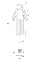
- FIG. 3A is a plan view of an example of the three-dimensional structure 20 manufactured by the modeling apparatus 10.
- FIG. 3B is a cross-sectional view taken along the line II of FIG.
- the three-dimensional structure 20 shown in FIG. 3 is a doll.
- the front-rear direction indicated by the arrow 20 a in FIG. 3 the left-right direction indicated by the arrow 20 b, and the upper-lower direction indicated by the arrow 20 c are respectively the X direction and Y direction when manufactured by the modeling apparatus 10. Corresponds to the Z direction.
- the three-dimensional structure 20 includes an internal part 21 and a peripheral part 22. Of the surrounding portion 22, at least a portion on the surface side of the three-dimensional structure 20 may be a decorative portion that is decorated with a pattern or color. Further, the inner portion 21 may be configured in white. The inner portion 21 is configured to be white, thereby favorably reflecting light entering from the surface side of the three-dimensional structure 20 and constituting a light reflecting portion that realizes coloring by subtractive color mixing.
- the inner part 21 is formed by stacking a plurality of layers of the modeling material 13a in the Z direction by the FDM method.
- the surrounding portion 22 is formed by stacking a plurality of layers of the modeling material 12a in the Z direction by an inkjet method.
- the thickness of each layer by the ink jet method is very thin such as 40 ⁇ m.
- the thickness of each layer by the FDM method is thicker than the thickness of each layer by the ink jet method. Therefore, when the three-dimensional structure 20 is manufactured, as shown in FIG. 4, the depth 22c in the Z direction of the groove 22b formed by stacking the plurality of layers 22a by the ink jet method is set to the FDM method. It is preferable that the control unit 18 controls the height 21c in the Z direction of the portion 21b formed by the layer 21a.
- the control unit 18 may flatten the surface of the layer 22a with a roller (not shown) after discharging the modeling material 12a forming the layer 22a in order to make the thicknesses of the plurality of layers 22a uniform.
- a roller not shown
- the control unit 18 flattens the surface of the layer 22a in order to increase the adhesion between the two adjacent layers 22a, and then discharges the modeling material 12a to the surface of the layer 22a by the modeling head 12. A large number of minute protrusions may be formed.
- the control unit 18 may detect the formation state of the three-dimensional structure 20 using a detection device such as a CCD (Charge-Coupled Device) during the formation of the three-dimensional structure 20. And the control part 18 judges whether the condition of formation of the three-dimensional structure 20 is progressing according to modeling data. When the control unit 18 determines that the state of formation of the three-dimensional structure 20 does not proceed according to the modeling data, the control unit 18 corrects the modeling data so that the outer shape of the three-dimensional structure 20 is the same as the original modeling data. Thereby, the accuracy of the external shape of the completed three-dimensional structure 20 is improved.
- the inner part 21 and the surrounding part 22 are formed in different ways by different materials and are overlapped with each other. The advantage that modeling data is corrected is great.
- the internal portion 21 is arranged in almost the entire area of the three-dimensional structure 20, but only a portion that needs to be reinforced in the three-dimensional structure 20 as shown in FIG. 5. May be arranged.
- the internal part 21 is formed by putting the liquid modeling material 13a in the groove 22b, and therefore the manufacturing of the internal part 21 can be facilitated.
- the internal portion 21 is formed by the FDM method.
- the internal portion 21 may be formed by the modeling material 13a by a method other than the FDM method.
- the internal part 21 may be formed with the modeling material 13a by an inkjet system.
- the groove 22b is formed by the peripheral portion 22, the modeling material 13a forming the inner portion 21 may be simply poured into the groove 22b. Therefore, the internal part 21 may be formed by a method in which the liquid modeling material 13a is discharged from the dispenser or the like toward the groove 22b, and then the discharged modeling material 13a is solidified.
- two dispensers filled with resin on one side and filled with a curing agent on the other side are prepared, and the dispenser on one side is prepared.
- the resin discharged from the liquid and the curing agent discharged from the other dispenser may be mixed in the groove 22b.
- both the inner portion 21 and the surrounding portion 22 are formed by the ink jet method, the structure of the modeling apparatus can be simplified, and therefore the manufacturing of the three-dimensional structure 20 can be facilitated.
- the modeling material 13a forming the inner portion 21 may be a curable liquid such as a two-component curable material when the inner portion 21 is formed by pouring the modeling material 13a into the groove 22b.
- the modeling material 13a that forms the internal portion 21 may be an FRP (Fiber Reinforced Plastics) -based material or may be blended with CNT (Carbon NanoTube).
- the protrusion part 22d may be formed in the groove
- the peripheral portion 22 is formed by an ink jet method.
- the surrounding portion 22 may be formed of the modeling material 12a by a method other than the inkjet method.
- the surrounding part 22 may be formed with the modeling material 12a by a FDM system.
- the three-dimensional structure 20 manufactured by the three-dimensional structure manufacturing method according to this embodiment includes the modeling material 13a that forms the internal portion 21 and the modeling material 12a that forms the surrounding portion 22.
- the rigidity in the solid state is large, so the modeling material 13a forming the internal part 21 can improve the rigidity in the thin part. Therefore, the three-dimensional structure manufacturing method according to the present embodiment can manufacture the three-dimensional structure 20 that can suppress the occurrence of breakage and bending at a thin portion.
- the internal formation step of forming the internal portion 21 with the modeling material 13a before the partial peripheral portion 22 of the three-dimensional structure 20 is formed by the surrounding formation step of forming the peripheral portion 22 with the modeling material 12a.
- the internal forming process may be executed after all the surrounding portions 22 of the three-dimensional structure 20 are formed by the surrounding forming process.
- the step of forming the molding material 13a for the internal portion 21 into the inside of the peripheral portion 22 through the hole by forming a hole communicating with the inside from the outside of the peripheral portion 22 in the peripheral forming step is the peripheral forming step. May be executed after all the surrounding portions 22 of the three-dimensional structure 20 are formed.
- FIG. 7 is a schematic front view of the modeling apparatus 110 used in the three-dimensional structure manufacturing method according to the present embodiment.
- the modeling apparatus 110 includes a modeling table 111 serving as a table for a three-dimensional model when a three-dimensional model is manufactured, and an inkjet that discharges a liquid modeling material 112 a toward the modeling table 111. And a modeling head 112 of the type.
- UV curable ink that is made solid by being irradiated with UV may be used.
- FIG. 8 is a block diagram of the modeling apparatus 110.
- the modeling apparatus 110 is configured with respect to one of the modeling table 111 and the modeling head 112 in the Y direction orthogonal to the Z direction as the ejection direction of the modeling material 112 a by the modeling head 112.
- a main scanning direction driving device 113 that relatively drives the other is provided.
- the Z direction is the vertical direction.
- the modeling apparatus 110 is a sub-scanning direction driving apparatus 114 that drives the other of the modeling table 111 and the modeling head 112 in the X direction (not shown) orthogonal to both the Y direction and the Z direction. It has.
- the modeling apparatus 110 includes a height direction driving device 115 that relatively drives one of the modeling table 111 and the modeling head 112 in the Z direction.
- the modeling apparatus 110 includes a communication unit 116 that is a communication device that communicates with an external apparatus via a network (not shown), and a control unit 117 that controls the entire modeling apparatus 110.
- the control unit 117 includes a CPU, a ROM that stores programs and various data in advance, and a RAM that is used as a work area of the CPU.
- the CPU executes a program stored in the ROM.
- the control unit 117 of the modeling apparatus 110 receives the modeling head 112, the main scanning direction driving device 113, the sub-scanning direction driving device 114, and the high level based on the input modeling data.
- a three-dimensional structure is manufactured by controlling the vertical drive device 115. Specifically, in the surrounding formation step, the control unit 117 discharges the liquid modeling material 112a by the modeling head 112 based on the modeling data, and then solidifies the discharged modeling material 112a, thereby performing the three-dimensional modeling. Form the peripheral part of the inner part of the object.
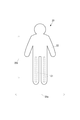
- FIG. 9A is a plan view of an example of the three-dimensional structure 120 manufactured by the modeling apparatus 110.
- FIG. 9B is a cross-sectional view taken along arrow II-II shown in FIG.
- the three-dimensional structure 120 shown in FIG. 9 is a doll.
- the front-rear direction indicated by an arrow 120a the left-right direction indicated by an arrow 120b
- the upper-lower direction indicated by an arrow 120c in FIG. Corresponds to the Z direction.
- the three-dimensional structure 120 includes an internal part 121 and a peripheral part 122.
- the inner part 121 is formed by a reinforcing material 121a other than the modeling material 112a discharged by the modeling head 112.
- a reinforcing material 121a metal, resin, wood, or the like may be used.
- a metal is used as the reinforcing material 121a
- a piano wire is preferable when it is thin and needs strength
- stainless steel is preferable when rust is a problem.
- a resin is used as the reinforcing material 121a
- an epoxy resin is preferable when adhesion to the modeling material 112a is required
- an FRP such as a resin containing glass fiber or a resin containing carbon fiber is preferable when rigidity is required. .
- the reinforcing material 121a has higher rigidity than the solid modeling material 112a. Further, it is preferable that the reinforcing material 121a has a higher bending strength than the solid modeling material 112a. Further, it is preferable that the reinforcing material 121a has a high impact value in addition to the bending strength as compared with the solid modeling material 112a.
- the surrounding portions 122 at least a portion on the surface side of the three-dimensional structure 120 may be a decorated portion decorated with a pattern or a color.
- the surrounding portion 122 is formed by stacking a plurality of layers 122a of the modeling material 112a in the Z direction by an inkjet method.
- control unit 117 may flatten the surface of the layer 122a with a roller (not shown) after discharging the modeling material 112a forming the layer 122a in order to make the thickness of the plurality of layers 122a uniform.
- the control unit 117 may flatten the surface of the layer 122a with a roller (not shown) after discharging the modeling material 112a forming the layer 122a in order to make the thickness of the plurality of layers 122a uniform.
- the three-dimensional structure 120 has a lower adhesion between the layers 122a. Therefore, when the external force is applied or the layer 122a expands or contracts due to the influence of temperature, the three-dimensional structure 120 is adjacent. Separation may occur between the two layers 122a.
- control unit 117 flattens the surface of the layer 122a in order to increase the adhesion between the two adjacent layers 122a, and then discharges the modeling material 112a to the surface of the layer 122a by the modeling head 112. A large number of minute protrusions may be formed.
- the control unit 117 may detect the state of formation of the three-dimensional structure 120 using a detection device such as a CCD during the formation of the three-dimensional structure 120. And the control part 117 judges whether the condition of formation of the three-dimensional structure 120 is progressing according to modeling data. When the control unit 117 determines that the state of formation of the three-dimensional structure 120 does not proceed according to the modeling data, the control unit 117 corrects the modeling data so that the outer shape of the three-dimensional structure 120 is the same as the original modeling data. Thereby, the accuracy of the external shape of the completed three-dimensional structure 120 is improved.
- a detection device such as a CCD
- the position of the reinforcing material 121a with respect to the peripheral portion 122 is detected and detected.
- the modeling data may be corrected based on the position.
- the peripheral portion 122 is superimposed on the internal portion 121 in the vertical direction, that is, the Z direction, there is a great advantage that the modeling data is corrected according to the situation. .
- the internal portion 121 is arranged in almost the entire area of the three-dimensional structure 120, but only the portions that need to be reinforced in the three-dimensional structure 120 as shown in FIG. 11. May be arranged.
- a part of the reinforcing material 121a constituting the internal part 121 may be outside the three-dimensional structure 120 as shown in FIG.
- the part 121b can be used for various purposes.
- the portion 121b of the reinforcing material 121a may be used as a connection portion for connecting to another member.
- the portion 121b may be simply inserted into and fixed to another member.
- the portion 121b can be coupled to the screw of the other member.
- the part 121b can be connected to another member in a state in which the angle can be changed with respect to the other member by forming a part such as a hinge that is a hinge.
- FIG. 13 is a diagram illustrating an example in which a hinge 121c is formed on the portion 121b. In FIG.
- the part 121b is provided with a hinge 121c and a connecting part 121d connected to a foot 123 as another member.
- the hinge 121c is formed integrally with the inner portion 121, and includes a portion 121f in which a hole 121e is formed at the center, a shaft 121g inserted into the hole 121e, and a hole (not shown) into which the shaft 121g is inserted. 121h.
- the connecting part 121d is formed integrally with the part 121h.
- the ankle joint of the doll is formed by the hinge 121c, but joints of other parts such as a knee joint and a hip joint may be formed by the same configuration. Further, in FIG.
- the hinge 121 c can realize rotation about the axis 121 g orthogonal to the extending direction of the internal portion 121, but centering on the axis extending in the extending direction of the internal portion 121. It may be possible to realize rotation in a direction other than the rotation shown in FIG.
- the portion 121b of the reinforcing material 121a may be used for energization.
- the portion 121b itself of the reinforcing material 121a may be used as an electrode.
- electric power is supplied from the outside of the three-dimensional structure 120 by inserting an electric wire inside the reinforcing material 121a. Can be done.
- the electric power supplied from the outside of the three-dimensional structure 120 is supplied to an electronic component attached to the three-dimensional structure 120.
- an LED Light Emitting Diode
- the three-dimensional structure 120 can be energized inside or can be realized by using the reinforcing material 121a.
- the modeling material 112a in a place where energization is necessary includes a particle of a conductive substance. By using the material 112a, internal energization can be realized.
- FIG. 14 is an external perspective view of the three-dimensional structure 220 manufactured by the modeling apparatus 110.
- FIG. 15A is a side view of the three-dimensional structure 220 in a state before the support material portion 223 formed by the support material 112b is removed.
- FIG. 15B is a bottom view of the three-dimensional structure 220 that is being manufactured by the modeling apparatus 110.
- the three-dimensional structure 220 shown in FIGS. 14 and 15 is a small bird model that stands on a disk-shaped table.
- the vertical direction indicated by the arrow 220a in FIGS. 14 and 15, the front-rear direction indicated by the arrow 220b, and the left-right direction indicated by the arrow 220c are respectively the X direction when manufactured by the modeling apparatus 110, It corresponds to the Y direction and the Z direction.
- the three-dimensional structure 220 includes an internal part 221 and a peripheral part 222.
- the internal portion 221 is formed by a reinforcing material 221a other than the modeling material 112a discharged by the modeling head 112.
- a reinforcing material 221a metal, resin, wood, or the like may be used.
- the reinforcing material 221a has higher rigidity than the solid modeling material 112a. Further, it is preferable that the reinforcing material 221a has a higher bending strength than the solid modeling material 112a. Furthermore, it is preferable that the reinforcing material 221a has a high impact value in addition to the high bending strength as compared with the solid modeling material 112a.
- At least a portion on the surface side of the three-dimensional structure 220 may be a decorated portion decorated with a pattern or a color.
- the surrounding portion 222 is formed by a plurality of layers of the modeling material 112a when a plurality of layers including at least one of the modeling material 112a and the support material 112b are stacked in the Z direction.
- the support material portion 223 is provided to support the peripheral portion 222 from the lower side in the vertical direction, that is, the Z direction, or from the horizontal direction when the peripheral portion 222 is formed.
- the support material portion 223 is formed by the liquid support material 112b being ejected by a head (not shown) similar to the modeling head 112, and then the ejected support material 112b being solid, like the surrounding portion 222. Is done.
- the support material portion 223 is formed by a plurality of layers of the support material 112b when a plurality of layers made of at least one of the modeling material 112a and the support material 112b are stacked in the Z direction.
- the support material 112b can be easily dissolved and removed by water or the like.
- the reinforcing material 221a is preferably a wire having a diameter smaller than the thickness of the three-dimensional structure 220. In the middle of the lamination, the reinforcing material 221a extending in the extending direction of the layers is disposed. Since the bent portion 221b extending in the direction perpendicular to the laminated surface, that is, the direction indicated by the arrow 220c is present at the end of the reinforcing material 221a, the three-dimensional structure 220 is compared with the case where the bent portion 221b is not present. Thus, the strength against twisting in the three-dimensional direction is increasing.
- the reinforcing material 221a is disposed in the peripheral portion 222 so as not to protrude to the outside of the three-dimensional structure 220. It is preferable that the reinforcing material 221a is not visible at least from the outside of the three-dimensional structure 220.
- the reinforcing material 221 a It is preferable to arrange
- the thin tail feather portion 231 is easily bent over time due to the weight of the tail feather itself. Further, when the three-dimensional structure 220 does not include the reinforcing material 221a, the thin leg portion 232 is easily broken by the weight of the portion above the leg. However, since the three-dimensional structure 220 includes the reinforcing material 221a, the occurrence of breakage and bending can be suppressed.
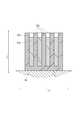
- FIG. 16 is a side cross-sectional view of a three-dimensional structure 320 that is being manufactured by the modeling apparatus 110.
- a three-dimensional structure 320 shown in FIG. 16 is a large bird model standing on a disk-shaped table.
- the three-dimensional structure 320 has a left-right direction (not shown), a front-rear direction indicated by an arrow 320b in FIG. 16, and an up-down direction indicated by an arrow 320c, respectively. Corresponds to the Z direction.
- the three-dimensional structure 320 includes an internal part 321 and a peripheral part 322.
- the internal portion 321 is formed by a reinforcing material 321a other than the modeling material 112a discharged by the modeling head 112.
- a reinforcing material 321a metal, resin, wood, or the like may be used.
- the reinforcing material 321a has higher rigidity than the solid modeling material 112a.
- the reinforcing material 321a has a higher bending strength than the solid modeling material 112a.
- the reinforcing material 321a has a high impact value in addition to the high bending strength as compared with the solid modeling material 112a.
- the peripheral portion 322 is formed by a plurality of layers of the modeling material 112a when a plurality of layers made of at least one of the modeling material 112a and the support material 112b are stacked in the Z direction.
- the support material portion 323 formed by the support material 112b is provided to support the peripheral portion 322 from the lower side in the vertical direction, that is, the Z direction, or from the horizontal direction when the peripheral portion 322 is formed.
- the support material portion 323 is formed by the liquid support material 112b being discharged by a head (not shown) similar to the modeling head 112, and then the discharged support material 112b being solid, like the surrounding portion 322. Is done.
- the support material portion 323 is formed by a plurality of layers of the support material 112b when a plurality of layers made of at least one of the modeling material 112a and the support material 112b are stacked in the Z direction.
- the support material 112b can be easily dissolved and removed by water or the like.
- the reinforcing material 321a has a surface shape.
- a surface-shaped reinforcing material 321a extending in the extending direction of the layer is disposed in the middle of the lamination.
- a plurality of reinforcing members 321a are arranged in the direction indicated by the arrow 320c. Since the space 320d in which the modeling material 112a does not exist is formed in a part of the three-dimensional structure 320 in the vertical direction, that is, the lower side of the reinforcing material 321a in the Z direction in the surrounding formation process, the necessary modeling material is formed. By significantly reducing the amount of 112a, weight and material costs can be reduced. In addition, since the weight of the three-dimensional structure 320 is reduced, it is possible to suppress the breakage or bending of the thin leg portion 331 due to the weight of the portion above the leg.
- the peripheral portion 322 includes a support portion 322a that supports the reinforcing material 321a in the vertical direction, that is, the lower side of the reinforcing material 321a in the Z direction, and forms a part of the boundary of the space 320d.
- the surface 322b of the support portion 322a is an inclined surface that does not overhang in the surrounding formation step, so the layer of the upper modeling material 112a in the vertical direction, that is, the Z direction is the lower modeling. It is reliably formed on the layer of material 112a. Therefore, the three-dimensional structure 320 can suppress the collapse of the shape of each layer in the space 320d, and as a result, can be formed with high accuracy.
- the reinforcing member 321a has a large number of holes 321b in at least a part of a portion where spaces 320d are formed on both sides in the direction orthogonal to the extending direction of the layers, that is, the direction indicated by the arrow 320c. It may be formed.
- the hole 321b is formed in the reinforcing material 321a, the amount of the necessary reinforcing material 321a can be significantly reduced, so that the weight and the material cost can be reduced. is there.
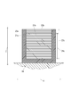
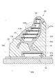
- FIG. 18 is a side cross-sectional view of a three-dimensional structure 420 that is being manufactured by the modeling apparatus 110.
- FIG. 19A is a cross-sectional view taken along the line IV-IV shown in FIG.
- a three-dimensional structure 420 shown in FIGS. 18 and 19A is a truncated cone having a diameter of the upper base larger than that of the lower base.
- the three-dimensional structure 420 has a left-right direction indicated by an arrow 420a in FIG. 19A, a front-rear direction indicated by an arrow 420b in FIGS. 18 and 19A, and a vertical direction indicated by an arrow 420c in FIG. This corresponds to the X direction, the Y direction, and the Z direction at the time of manufacture by the apparatus 110.
- the three-dimensional structure 420 includes an inner part 421 and a surrounding part 422.
- the internal portion 421 is formed by a reinforcing material 421a other than the modeling material 112a discharged by the modeling head 112.
- a reinforcing material 421a metal, resin, wood, or the like may be used.
- the reinforcing material 421a has higher rigidity than the solid modeling material 112a. Further, it is preferable that the reinforcing material 421a has a higher bending strength than the solid modeling material 112a. Furthermore, it is preferable that the reinforcing material 421a has a high impact value in addition to the bending strength as compared with the solid modeling material 112a.
- the peripheral portion 422 is formed by a plurality of layers of the modeling material 112a when a plurality of layers made of at least one of the modeling material 112a and the support material 112b are stacked in the Z direction.
- the support material portion 423 formed by the support material 112b is provided to support the peripheral portion 422 from the lower side in the vertical direction, that is, the Z direction, or from the horizontal direction when the peripheral portion 422 is formed.
- the support material portion 423 is formed by the liquid support material 112b being discharged by a head (not shown) similar to the modeling head 112, and then the discharged support material 112b being solid, like the surrounding portion 422. Is done.
- the support material portion 423 is formed by a plurality of layers of the support material 112b when a plurality of layers made of at least one of the modeling material 112a and the support material 112b are stacked in the Z direction.
- the support material 112b can be easily dissolved and removed by water or the like.
- the reinforcing material 421a has a surface shape.
- a surface-shaped reinforcing material 421a extending in the extending direction of the layers is arranged in the middle of the lamination.
- a plurality of reinforcing members 421a are arranged in the direction indicated by the arrow 420c. Since the space 420d in which the modeling material 112a does not exist is formed in the part of the three-dimensional structure 420 in the vertical direction, that is, the lower side of the reinforcing material 421a in the Z direction in the surrounding formation process, the necessary modeling material is formed. By significantly reducing the amount of 112a, weight and material costs can be reduced.
- the surrounding portion 422 includes a support portion 422a that supports the reinforcing material 421a on the lower side in the vertical direction, that is, the Z direction in the surrounding forming step, and constitutes a part of the boundary of the space 420d.
- the surface 422b of the support portion 422a is an inclined surface that does not overhang in the periphery forming step, and therefore, the layer of the upper modeling material 112a in the vertical direction, that is, the Z direction is the lower modeling. It is reliably formed on the layer of material 112a. Therefore, the three-dimensional structure 420 can suppress the collapse of the shape of each layer in the space 420d, and as a result, can be formed with high accuracy.
- the support portion 422a includes an end portion support portion 422c that supports the reinforcing material 421a at an end portion of the reinforcing material 421a in the extending direction of the layer, and a reinforcing material 421a in a portion other than the end portion of the reinforcing material 421a in the extending direction of the layer. And a non-end support portion 422d for supporting the.
- the non-end support part 422d may be a wall that partitions the space 420d as shown in FIG. 19A, or may be a pillar that does not partition the space 420d as shown in FIG. 19B.
- the reinforcing material 421a Since the three-dimensional structure 420 is provided with the non-end support part 422d by the modeling material 112a at a portion of the reinforcing material 421a that is long in the extending direction of the layer, the reinforcing material 421a is warped. As a result, it can be formed with high accuracy.
- the reinforcing member 421a has a large number of holes 421b in at least a part of a portion where spaces 420d are formed on both sides in the direction perpendicular to the extending direction of the layers, that is, the direction indicated by the arrow 420c. It may be formed.
- the hole 421b is formed in the reinforcing material 421a, the three-dimensional structure 420 can reduce the amount of the necessary reinforcing material 421a, thereby reducing the weight and the material cost. is there.
- the peripheral portion is formed by an ink jet method.
- the surrounding portion may be formed by the modeling material 112a by a method other than the ink jet method.
- the surrounding portion may be formed of the modeling material 112a by the FDM method.
- the three-dimensional structure manufactured by the three-dimensional structure manufacturing method according to the present embodiment is compared with the solid state forming material in which the reinforcing material forming the inner portion forms the surrounding portion. Since the rigidity is large, the rigidity in the thin portion can be improved by the reinforcing material. Therefore, the three-dimensional structure manufacturing method according to the present embodiment can manufacture a three-dimensional structure that can suppress the occurrence of breakage and bending at a thin portion.
- the reinforcing material is disposed inside the three-dimensional structure, it is possible to suppress the appearance from being deteriorated by the reinforcing material, unlike the configuration in which the reinforcing material is disposed outside. Moreover, since the reinforcing material is arrange
- the three-dimensional structure can improve convenience when the reinforcing material is used for connection to other members in addition to reinforcement.
- the internal forming process in which the reinforcing material is arranged in the peripheral portion is executed before the partial peripheral portion of the three-dimensional structure is formed by the peripheral forming step of forming the peripheral portion with the modeling material. Therefore, it is possible to easily fix the reinforcing material inside the three-dimensional structure as compared with the method of inserting the reinforcing material into the peripheral part after all the peripheral parts of the three-dimensional structure are formed by the peripheral forming process. it can.
- the internal formation process which inserts a reinforcing material in a three-dimensional structure after all the surrounding parts of a three-dimensional structure are formed by the periphery formation process may be performed.
- the step of inserting the reinforcing material into the inside of the surrounding portion through this hole It may be performed after the surrounding portion of the is formed.
- the internal formation process which inserts a reinforcing material in a three-dimensional structure is performed after all the peripheral parts of the three-dimensional structure are formed by the peripheral formation process, a part of the three-dimensional structure is performed by the peripheral formation process. Compared to a case where an internal forming process in which a reinforcing material is disposed on the peripheral portion before the peripheral portion is formed, manufacturing of the peripheral portion can be facilitated.
- FIG. 21 is a schematic front view of the modeling apparatus 510 according to the present embodiment.
- 21 is a basic structure of the modeling apparatus according to the present embodiment.
- the modeling apparatus 510 includes a support member 511 that supports the three-dimensional structure when the three-dimensional structure is manufactured.
- the modeling apparatus 510 includes an inkjet-type modeling material head 512 that ejects a liquid modeling material 512 a toward the support member 511 and an inkjet-type support material head that ejects a liquid support material 513 a toward the support member 511. 513 and a carriage 515 on which a modeling material 512a discharged by the modeling material head 512 and an ultraviolet irradiation device 514 for irradiating the support material 513a discharged by the support material head 513 with ultraviolet rays 514a are mounted. I have.
- the modeling material 512a is a UV curable ink that is solidified by being irradiated with UV.
- the modeling material 512a is modeling ink that becomes a material of a three-dimensional modeled object.
- CMYK Cyan, Magenta, Yellow, Black
- the modeling apparatus 510 may include a modeling material head 512 for each type of the modeling material 512a.
- the support material 513a is a UV curable ink that is solidified by being irradiated with UV.
- the support material 513a becomes a material of the support material portion that supports the three-dimensional structure in order to form a three-dimensional structure having an arbitrary shape with the modeling ink.
- the support material 513a may be CMYK color ink.
- the support material 513a is ink that can be easily removed by a specific liquid such as water.
- the support material portion is formed on the lower side in the vertical direction or in the horizontal direction with respect to the three-dimensional modeled object.
- the support material portion is formed on the lower side in the vertical direction with respect to the overhang portion and supports the overhang portion.
- the modeling apparatus 510 may include a support material head 513 for each type of support material 513a.
- the modeling apparatus 510 includes a carriage 517 on which a laser cutter 516 that performs cutting with a laser beam 516a is mounted.
- the laser beam 516a may be a pulse laser or a CW (Continuous Wave) laser.
- the modeling material 512a or the porous sheet reacts with the surrounding gas due to heat generated when the modeling material 512a or a porous sheet described later is irradiated with laser light 516a, and the modeling material 512a or the porous sheet is burnt or oxidized. In order to suppress this, it is preferable that the cutting process by the laser cutter 516 is performed in an inert gas.
- FIG. 22 (a) is a schematic front view of a part of the modeling apparatus 510 when the laser beam 516a is irradiated in the vertical direction.
- FIG. 22B is a schematic front view of a part of the modeling apparatus 510 when the laser beam 516a is irradiated in a direction different from the vertical direction.
- the laser cutter 516 is mounted on the carriage 517 so that the direction can be changed, and by changing the direction, the laser beam 516 a is irradiated in an arbitrary direction in which the vertical component is downward. Is possible. Since the irradiation direction of the laser beam 516a by the laser cutter 516, that is, the cutting direction by the laser beam 516a can be changed, the surface of the three-dimensional structure cut out by the laser beam 516a can be smoothed.
- a porous sheet 531 in which a large number of holes are formed is supported on a support member 511 via a release sheet 532.
- the perforated sheet 531 is a sheet in which a large number of holes are formed so that the modeling material 512a and the support material 513a can pass through or permeate through the holes.
- a sheet having a mesh hole such as a film having a mesh knitted with plastic fiber or metal wire, or a cloth can be used.
- a sheet in which holes not depending on the mesh are formed such as an etching film in which a large number of holes are formed by etching, may be employed.
- the release sheet 532 is a member that can easily peel the porous sheet 531 on which the modeling material 512a is adhered from the release sheet 532 itself. Further, the release sheet 532 is a member that can be easily separated from the support member 511 as well.
- the porous sheet 531 may be directly supported by the support member 511 without using the release sheet 532.
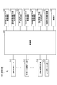
- FIG. 23 is a block diagram of the modeling apparatus 510.
- the modeling apparatus 510 includes a Y direction orthogonal to the Z direction as the ejection direction of the modeling material 512 a by the modeling material head 512 and the ejection direction of the support material 513 a by the support material head 513. Further, a modeling main scanning direction driving device 521 for driving the other of the support member 511 and the carriage 515 relative to the other is provided.
- the Z direction is the vertical direction.
- the modeling apparatus 510 is a modeling sub-scanning direction driving apparatus that relatively drives one of the support member 511 and the carriage 515 in the X direction (not shown) orthogonal to both the Y direction and the Z direction. 522.
- the modeling apparatus 510 includes a modeling height direction driving apparatus 523 that relatively drives one of the support member 511 and the carriage 515 in the Z direction.
- the modeling apparatus 510 includes a cutting main scanning direction driving device 524 that relatively drives one of the support member 511 and the carriage 517 in the Y direction.
- the modeling apparatus 510 includes a cutting sub-scanning direction driving device 525 that relatively drives one of the support member 511 and the carriage 517 in the X direction.
- the modeling apparatus 510 includes a cutting height direction driving device 526 that relatively drives one of the support member 511 and the carriage 517 in the Z direction.
- the modeling apparatus 510 changes the direction of the laser cutter 516 relative to the carriage 517 in order to change the irradiation direction of the laser beam 516a by the laser cutter 516 to an arbitrary direction in which the vertical component is downward. It has.
- the modeling apparatus 510 includes a communication unit 528 that is a communication device that communicates with an external apparatus via a network (not shown), and a control unit 529 that controls the entire modeling apparatus 510.
- the control unit 529 includes a CPU, a ROM that stores programs and various data in advance, and a RAM that is used as a work area of the CPU.
- the CPU executes a program stored in the ROM.
- the control unit 529 of the modeling apparatus 510 receives the modeling material head 512, the support material head 513, the ultraviolet irradiation device 514, and the laser cutter based on the input modeling data.
- a three-dimensional structure is manufactured by controlling the vertical direction driving device 526 and the cutting direction changing device 527.
- the control unit 529 discharges the liquid modeling material 512a toward the porous sheet 531 by the modeling material head 512, and then applies ultraviolet rays to the modeling material 512a attached to the porous sheet 531 by the ultraviolet irradiation device 514. By irradiating, the modeling material 512a is cured to be solid.
- the control unit 529 discharges the liquid support material 513a toward the porous sheet 531 by the support material head 513 and then attaches the support to the porous sheet 531. By irradiating the material 513a with ultraviolet rays by an ultraviolet irradiation device 514, the support material 513a is cured to be solid.
- the control unit 529 controls the modeling main scanning direction driving device 521 and the modeling sub-scanning direction driving device 522 based on the modeling data, and the modeling material 512a and the support material 513a attached to the porous sheet 531 as described above.
- the solid material is formed into a single porous sheet 531 with the modeling material portion formed of the modeling material 512a and the support material portion formed of the support material 513a.
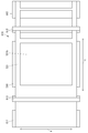
- FIG. 24 is a schematic front sectional view of a part of the modeling apparatus 510 in a state in which the modeling material portion 541 and the support material portion 542 are formed on one porous sheet 531.
- control unit 529 controls the modeling material head 512, the support material head 513, the ultraviolet irradiation device 514, the modeling main scanning direction driving device 521, and the modeling sub-scanning direction driving device 522 based on the modeling data.
- a modeling material portion 541 and a support material portion 542 are formed on one porous sheet 531.
- the control unit 529 forms the modeling material portion 541 and the support material portion 542 on one perforated sheet 531, and then based on the modeling data, the cutting main scanning direction driving device 524, the cutting sub-scanning direction driving device 525, and the cutting While controlling the direction changing device 527, the laser cutter 516 irradiates the porous sheet 531 with laser light 516a, thereby cutting the porous sheet 531 and part of the three-dimensional structure in the porous sheet 531. A part other than the modeled object is made separable.
- FIG. 25 is a schematic front cross-sectional view of a part of the modeling apparatus 510 in which a part 543 of the three-dimensional structure in one porous sheet 531 and a part other than the three-dimensional structure can be separated. .
- control unit 529 controls the laser cutter 516, the cutting main scanning direction driving device 524, the cutting sub-scanning direction driving device 525, and the cutting direction changing device 527, as shown in FIG.
- a part 543 of the three-dimensional structure in one porous sheet 531 and a part other than the three-dimensional structure are made separable.
- the width 543a of the part 543 of the three-dimensional structure is defined by printing by the modeling material head 512.
- the modeling material portion 541 has a three-dimensional structure in which the width 541a of the modeling material portion 541 is cut by the laser cutter 516 as shown in FIG. It is preferable that the portion 543 is wider than the width 543a so as to include the portion 543 of the three-dimensional structure.
- the width 541a may be the same as the width 543a.
- the controller 529 makes a part 543 of the three-dimensional structure in the single porous sheet 531 separable from a part other than the three-dimensional structure, and then drives the height direction for modeling based on the modeling data.
- the distance between the supporting member 511 and the carriage 515 and the carriage 517 in the vertical direction is increased by the distance corresponding to the thickness of the single porous sheet 531.
- a new porous sheet 531 is stacked on the upper side in the vertical direction of the porous sheet 531 in which a part 543 of the three-dimensional structure and a portion other than the three-dimensional structure are separable.
- the modeling height direction driving device 523 and the cutting height direction driving are performed.
- the device 526 may be the same device.
- FIG. 26 is a schematic front sectional view of a part of the modeling apparatus 510 in a state in which the three-dimensional structure 550 is manufactured.
- FIG. 27 is an external perspective view of the three-dimensional structure 550 shown in FIG.
- the control unit 529 manufactures a three-dimensional structure 550 as shown in FIG. 26 by repeating the above operation.
- the three-dimensional structure 550 is configured such that a layer is formed for each thickness of the porous sheet 531 and a plurality of layers are stacked.
- the three-dimensional structure 550 is in a state in which a part 543 of the three-dimensional structure and a part other than the three-dimensional structure can be separated in each porous sheet 531. Therefore, the operator can take out the three-dimensional structure 550 as shown in FIG.
- a three-dimensional structure 550 shown in FIG. 27 is a hemispherical three-dimensional object in which a hemispherical groove 550a is formed.
- the amount of the modeling material 512a attached to the porous sheet 531 may be an amount by which the porous sheet 531 and the porous sheet 531 immediately below the porous sheet 531 are adhered by the modeling material 512a.
- the amount of the modeling material portion 541 may not be soaked uniformly.
- the porous sheet 531 is cut by the laser cutter 516, another porous sheet 531 is overlaid on the porous sheet 531, and the lower porous sheet 531 is cut in the horizontal position.
- the modeling material 512a is attached to the upper porous sheet 531 at a position corresponding to the position, the modeling material 512a attached to the upper porous sheet 531 may enter the cut of the lower porous sheet 531. . If the modeling material 512a that has entered the cut is cured by ultraviolet rays, the three-dimensional modeled object 550 may not be taken out.
- the control unit 529 cuts the porous sheet 531 with the laser cutter 516
- the control unit 529 fills the cut with the support material 513a, and then positions the upper porous sheet 531 on the porous sheet 531 in the horizontal direction.
- the modeling material 512a may be prevented from entering the cut from the upper porous sheet 531 and the three-dimensional model 550 may not be taken out. Can be reduced.
- FIG. 28A is a schematic cross-sectional view of a porous sheet 531 in which a cut 531 a is cut by a laser cutter 516.
- FIG. 28B is a schematic cross-sectional view of the porous sheet 531 that has been subjected to subsequent steps in the state shown in FIG.
- FIG. 28C is a schematic cross-sectional view of the porous sheet 531 that has been subjected to subsequent steps in the state shown in FIG.
- FIG. 28D is a schematic cross-sectional view of the porous sheet 531 that has been subjected to the subsequent process in the state shown in FIG.
- FIG. 28A when the control unit 529 cuts 531 a into the porous sheet 531 with the laser cutter 516, another porous sheet 531 is overlaid on the porous sheet 531 to further form the modeling material 512 a.
- the notch 531a of the porous sheet 531 with the notch 531a is filled with the support material 513a as shown in FIG. 28B, and the support material 513a is cured by the ultraviolet ray 514a.
- the control unit 529 attaches the modeling material 512a as shown in FIG. 28C by superimposing another porous sheet 531 on the porous sheet 531 in which the notch 531a is filled with the support material 513a, and the modeling material portion 541 is attached.
- control unit 529 makes a cut 531a in the porous sheet 531 on which the modeling material portion 541 is formed, as shown in FIG. Note that the support material 513a that is hardened by filling the cuts 531a can be easily removed with water or the like.
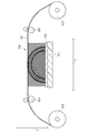
- FIG. 29 is a schematic front view showing a modeling apparatus 610 which is an example of the modeling apparatus 510.
- 21 can be realized as the modeling apparatus 610 shown in FIG.
- the modeling apparatus 610 includes a feeding roller 611 around which the porous sheet 531 is wound in order to feed out the porous sheet 531, and a winding roller 612 around which the porous sheet 531 is wound in order to wind up the porous sheet 531. And a plurality of rollers 613 for extending the perforated sheet 531 that is fed by the feeding roller 611 and wound by the winding roller 612 in a direction orthogonal to the Z direction.
- the central axes of the feeding roller 611, the take-up roller 612, and the roller 613 extend in the X direction.
- the feeding roller 611, the take-up roller 612, and the roller 613 are supported so as to be rotatable around their respective central axes.
- FIG. 30 is a block diagram of the modeling apparatus 610.
- the configuration of the control system of the modeling apparatus 610 is the same as that shown in FIG. 23 except that it includes a roller rotating device 621 that controls the rotation of the feeding roller 611 and the take-up roller 612. It is.
- the roller rotating device 621 moves the perforated sheet 531 relative to the support member 511, and constitutes the moving means of the present invention.
- the modeling main scanning direction driving device 521 drives only the carriage 515 in the Y direction among the support member 511 and the carriage 515.
- the modeling sub-scanning direction driving device 522 drives only the carriage 515 of the support member 511 and the carriage 515 in the X direction.
- the cutting main scanning direction driving device 524 drives only the carriage 517 in the Y direction among the support member 511 and the carriage 517.
- the cutting sub-scanning direction driving device 525 drives only the carriage 517 out of the support member 511 and the carriage 517 in the X direction.
- the modeling height direction driving device 523 and the cutting height direction driving device 526 are the same device, and only the support member 511 among the support member 511, the carriage 515, and the carriage 517 is driven in the Z direction.
- FIG. 31 is a schematic plan view of a part of the modeling apparatus 610.
- control unit 529 of the modeling apparatus 610 forms the modeling material portion 541 and the support material portion 542 on the porous sheet 531, and then the part 543 of the three-dimensional modeling object in the porous sheet 531 and the three-dimensional modeling object.
- the part 531b of a specific range is cut out from the porous sheet 531 as shown in FIG.
- control unit 529 supports the cutting height direction driving device 526, which is the modeling height direction driving device 523, based on the modeling data, thereby supporting only the distance corresponding to the thickness of one porous sheet 531.
- the member 511 is moved downward in the vertical direction.
- control unit 529 operates the roller rotating device 621 so as to wind up the porous sheet 531 by the winding roller 612 by a distance longer than the length of the portion 531b in the Y direction.
- the perforated sheet 531 is fed from the feed roller 611 by the amount wound by the take-up roller 612.
- the control unit 529 urges the feeding roller 611 by the roller rotating device 621 in the direction opposite to the rotation direction when the porous sheet 531 is fed, and the winding roller 612 is made porous.
- the porous sheet 531 that is fed by the feeding roller 611 and wound by the winding roller 612 is horizontal with respect to the support member 511.
- a tension in the Y direction is applied to the perforated sheet 531 that overlaps the positions in FIG.
- FIG. 32 is a schematic front sectional view of a part of the modeling apparatus 610.
- the control unit 529 manufactures a three-dimensional structure 550 as shown in FIG. 32 by repeating the above operation.
- a three-dimensional structure 550 shown in FIG. 32 has a layer formed for each thickness of the porous sheet 531 and is formed by stacking a plurality of layers.
- the porous sheet 531 has been transported in the Y direction as described above, but may be transported in the X direction. That is, in the modeling apparatus 610, the central axes of the feeding roller 611, the take-up roller 612, and the roller 613 may extend in the Y direction.
- the modeling apparatus 610 cuts a part of the porous sheet 531, that is, the part 531 b by the laser cutter 516, and then moves the porous sheet 531 relative to the support member 511 by the roller rotating device 621.
- a perforated sheet 531 is laminated on the side opposite to the support member 511 side with respect to the portion 531b cut out by the laser cutter 516 and supported by the support member 511.
- FIG. 33 is a schematic front view showing a modeling apparatus 710 that is an example of the modeling apparatus 510.
- 21 can be realized as a modeling apparatus 710 shown in FIG.
- the modeling apparatus 710 includes a feeding roller 711 around which the porous sheet 531 is wound in order to feed out the porous sheet 531.
- the central axis of the feeding roller 711 extends in the X direction.
- the feeding roller 711 is supported so as to be rotatable around the central axis.
- the support member 511 of the modeling apparatus 710 includes a sheet fixing portion 511a to which the porous sheet 531 is fixed.
- a central axis 511b of the support member 511 of the modeling apparatus 710 extends in the X direction. And the supporting member 511 of the modeling apparatus 710 is supported so that rotation around the central axis 511b is possible.
- FIG. 34 is a block diagram of the modeling apparatus 710.
- the configuration of the control system of the modeling apparatus 710 includes a support member rotation device 721 that controls the rotation of the support member 511 and a roller rotation device 722 that controls the rotation of the feed roller 711.
- the configuration is the same as that shown in FIG.
- the support member rotating device 721 rotates the support member 511 and constitutes the rotating means of the present invention.
- the modeling main scanning direction driving device 521 drives only the carriage 515 in the Y direction among the support member 511 and the carriage 515.
- the modeling sub-scanning direction driving device 522 drives only the carriage 515 of the support member 511 and the carriage 515 in the X direction.
- the modeling height direction driving device 523 drives only the carriage 515 in the Z direction among the support member 511 and the carriage 515.
- the cutting main scanning direction driving device 524 drives only the carriage 517 in the Y direction among the support member 511 and the carriage 517.
- the cutting sub-scanning direction driving device 525 drives only the carriage 517 out of the support member 511 and the carriage 517 in the X direction.
- the cutting height direction driving device 526 drives only the carriage 517 in the Z direction among the support member 511 and the carriage 517.
- control unit 529 of the modeling apparatus 710 forms the modeling material portion 541 and the support material portion 542 on the porous sheet 531, and the part 543 of the three-dimensional modeling object in the porous sheet 531 and the three-dimensional modeling object. After making it a state which can be separated from other parts, by controlling the height direction driving device for modeling 523 and the height direction driving device for cutting 526 for cutting based on the modeling data, the thickness of one perforated sheet 531 The carriage 515 and the carriage 517 are moved upward in the vertical direction by the distance of.
- the control unit 529 contacts the carriage 515 and the carriage 517 with the perforated sheet 531 wound around the support member 511 or the support member 511.
- the carriage 515 is driven by at least one of the modeling main scanning direction driving device 521 and the modeling sub-scanning direction driving device 522 at a position where the cutting is not performed, and the cutting main scanning direction driving device 524 and the cutting sub-scanning direction driving device 525 are driven.
- the carriage 517 is driven by at least one of them.
- the control unit 529 operates the support member rotating device 721 so that the support member 511 rotates 180 degrees around the central axis 511b in a specific direction.
- the perforated sheet 531 is fed from the feed roller 711 by the amount wound by the support member 511.
- the control unit 529 is fed by the feed roller 711 by biasing the feed roller 711 by the roller rotating device 722 in a direction opposite to the rotation direction when the perforated sheet 531 is fed.
- the tension in the Y direction is applied to the perforated sheet 531 whose position in the horizontal direction overlaps the support member 511 and whose position in the vertical direction is the uppermost side.
- FIG. 35 is a schematic front sectional view of a part of the modeling apparatus 710.
- the control unit 529 manufactures a three-dimensional structure 550 as shown in FIG. 35 by repeating the above operation.
- a three-dimensional structure 550 shown in FIG. 35 has a layer for each thickness of the porous sheet 531 and is configured by stacking a plurality of layers.
- the modeling apparatus 710 can manufacture a three-dimensional structure 550 on each of the two surfaces of the support member 511. Since the hardened modeling material 512a and the support material 513a are attached to the surface of the support member 511 with a certain degree of adhesive force, the three-dimensional structure 550 is positioned below the support member 511 in the vertical direction. Even if a certain amount of force is present, the three-dimensional structure 550 does not fall from the support member 511 unless a certain amount of force is applied.
- the porous sheet 531 has been conveyed in the Y direction in the above, but may be conveyed in the X direction. That is, in the modeling apparatus 710, the central axis of the feeding roller 711 and the central axis 511b of the support member 511 may extend in the Y direction.
- the support member rotating device 721 rotates the support member 511 to wind the porous sheet 531 around the support member 511 and stack the porous sheet 531.
- the modeling apparatus 710 facilitates the stacking of the plurality of porous sheets 531 on the support member 511, and thus can facilitate the manufacture of the three-dimensional modeled object 550.
- the modeling apparatus 610 shown in FIG. 29 maintains the position of the porous sheet 531 with respect to the carriage 515 and the carriage 517 by the balance of the pulling force of the porous sheet 531 by the feeding roller 611 and the take-up roller 612.
- the modeling apparatus 710 shown in FIG. 33 maintains the position of the porous sheet 531 with respect to the carriage 515 and the carriage 517 by the pulling force of the porous sheet 531 only by the feeding roller 711. Therefore, the modeling apparatus 710 can maintain the position of the porous sheet 531 with respect to the carriage 515 and the carriage 517 with higher accuracy than the modeling apparatus 610.
- the modeling device 710 includes two surfaces on which the three-dimensional structure 550 is formed in the support member 511 in the rotation direction, and can manufacture the three-dimensional structure 550 on each of the two surfaces of the support member 511. Since it is possible, compared with the modeling apparatus 610, it is possible to manufacture the some three-dimensional molded item 550 at high speed.
- FIG. 36 is a schematic front view showing a modeling apparatus 810 that is an example of the modeling apparatus 510.
- the modeling apparatus 510 shown in FIG. 21 can be realized as the modeling apparatus 810 shown in FIG.
- control unit 529 is configured so that the shape of the support member 511 and the support member 511 rotate around the central axis 511b in 90 degrees instead of 180 degrees in a specific direction. Except for operating the support member rotating device 721, it is the same as the modeling apparatus 710 shown in FIG.
- the modeling apparatus 810 has the porous sheet 531 conveyed in the Y direction, but may be conveyed in the X direction. That is, in the modeling apparatus 810, the central axis of the feeding roller 811 and the central axis 511b of the support member 511 may extend in the Y direction.
- the modeling apparatus 810 rotates the support member 511 to wind the porous sheet 531 around the support member 511 and stack the porous sheet 531 in the same manner as the modeling apparatus 710 shown in FIG. With this configuration, the modeling apparatus 810 facilitates the stacking of the plurality of porous sheets 531 on the support member 511, and thus can facilitate the manufacture of the three-dimensional modeled object 550.
- the modeling apparatus 810 includes four surfaces on which the three-dimensional structure 550 is formed in the rotation direction of the support member 511, and can manufacture the three-dimensional structure 550 on each of the four surfaces of the support member 511. Therefore, a plurality of three-dimensional structures 550 can be manufactured at a higher speed than the modeling apparatus 710.
- FIG. 37 is a schematic front view showing a modeling apparatus 910 that is an example of the modeling apparatus 510.
- FIG. 38 is a schematic side view of the modeling apparatus 910.
- the modeling apparatus 510 shown in FIG. 21 can be realized as the modeling apparatus 910 shown in FIGS.
- the modeling apparatus 910 includes a feeding roller 911 around which the perforated sheet 531 is wound in order to feed out the perforated sheet 531.
- the central axis of the feeding roller 911 extends in the Y direction.
- the feeding roller 911 is supported so as to be rotatable around the central axis.
- the support member 511 of the modeling apparatus 910 includes a sheet fixing portion 511a to which the porous sheet 531 is fixed.
- the support member 511 of the modeling apparatus 910 has a cylindrical shape.
- the central axis of the support member 511 of the modeling apparatus 910 extends in the Y direction.
- the support member 511 of the modeling apparatus 910 is supported so as to be rotatable around the central axis.
- the configuration of the control system of the modeling apparatus 910 is the same as the configuration shown in FIG.
- the modeling main scanning direction driving device 521 drives only the carriage 515 in the Y direction among the support member 511 and the carriage 515.
- the modeling height direction driving device 523 drives only the carriage 515 in the Z direction among the support member 511 and the carriage 515.
- the cutting main scanning direction driving device 524 drives only the carriage 517 in the Y direction among the support member 511 and the carriage 517.
- the cutting height direction driving device 526 drives only the carriage 517 in the Z direction among the support member 511 and the carriage 517.
- the modeling sub-scanning direction driving device 522 and the cutting sub-scanning direction driving device 525 are the same device.
- the support member 511 Of the support member 511, the carriage 515, and the carriage 517, only the support member 511 is the central axis of the support member 511.
- the roller rotating device 621 rotates the feeding roller 911.
- the roller rotating device 621 controls the rotation of the feeding roller 911.
- the control unit 529 discharges the liquid modeling material 512a toward the porous sheet 531 by the modeling material head 512, and then applies ultraviolet rays to the modeling material 512a attached to the porous sheet 531 by the ultraviolet irradiation device 514. By irradiating, the modeling material 512a is cured to be solid.
- the control unit 529 is formed of the modeling material 512a by solidifying the modeling material 512a attached to the porous sheet 531 as described above while controlling the modeling main scanning direction driving device 521 based on the modeling data.
- the formed modeling material portion 541 is formed on the porous sheet 531.
- the control unit 529 controls the cutting main scanning direction driving device 524 and the cutting direction changing device 527 based on the modeling data, and the laser cutter 516 emits the laser beam 516a. By irradiating the porous sheet 531, the porous sheet 531 is cut.
- the control unit 529 controls the modeling sub-scanning direction driving device 522 based on the modeling data, solidifies the modeling material 512a attached to the porous sheet 531 as described above, and uses the laser cutter 516 to form the porous sheet 531. Is formed on the porous sheet 531, and a part of the three-dimensional structure in the porous sheet 531 can be separated from a part other than the three-dimensional structure.
- the control unit 529 urges the feeding roller 911 by the roller rotating device 621 in the direction opposite to the rotation direction when the perforated sheet 531 is fed, thereby supporting the porous sheet 531 fed by the feeding roller 911.
- a tension in the X direction is applied to the porous sheet 531 whose position in the horizontal direction overlaps the member 511 and whose position in the vertical direction is the uppermost side.
- the control unit 529 rotates the support member 511 by the modeling sub-scanning direction driving device 522 so that the distance between the carriage 515 and the carriage 517 and the porous sheet 531 at the position facing the carriage 515 is within a specific distance range.
- the shaping height direction driving device 523 and the cutting height direction driving device 526 are controlled according to the above.
- the control unit 529 can manufacture the tube-shaped three-dimensional structure 550 surrounding the support member 511 by repeating the above operation.
- the modeling sub-scanning direction driving device 522 and the cutting sub-scanning direction driving device 525 as the rotating means of the present invention rotate the support member 511 to wind the porous sheet 531 around the support member 511 and stack the porous sheets 531.
- the modeling apparatus 910 facilitates the stacking of the plurality of porous sheets 531 on the support member 511, and thus can facilitate the manufacture of the three-dimensional modeled object 550.
- the modeling material head 512 of the modeling apparatus 910 causes the modeling materials 512a ejected in a state in which the rotation angles of the support members 511 by the modeling sub-scanning direction driving device 522 and the cutting sub-scanning direction driving device 525 are different from each other.
- the modeling apparatus 910 has a shape corresponding to the rotation of the support member 511 by the modeling sub-scanning direction driving device 522 and the cutting sub-scanning direction driving device 525, such as the tube-shaped three-dimensional modeling object 550.
- Article 550 can be manufactured.
- the three-dimensional structure 550 improves the mechanical strength by adhering the porous sheets 531 to each other with the modeling material 512a, so that it is possible to suppress the occurrence of breakage and bending in a thin portion. Suitable as an original model.
- the modeling material 512a is ultraviolet curable ink
- the modeling material 512a is cured at high speed with high accuracy. Therefore, the three-dimensional structure 550 can be manufactured at high speed and with high accuracy.
- modeling material 512a may be ink other than ultraviolet curable ink, or the porous sheets 531 may be bonded to each other by a method other than the ink jet method.
- the modeling material 512a may be attached to the porous sheet 531 with a dispenser.
- the modeling apparatuses 510, 610, 710, 810, and 910 improve the mechanical strength by bonding the porous sheets 531 to each other with the modeling material 512 a, and the high accuracy of the three-dimensional structure 550 from the porous sheet 531 by the laser cutter 516. Therefore, it is possible to manufacture a highly accurate three-dimensional structure 550 having high mechanical strength. Therefore, the modeling apparatuses 510, 610, 710, 810, and 910 are suitable for manufacturing the three-dimensional modeled object 550 that can suppress the occurrence of breakage and bending in a thin portion.
- the modeling material 512a used in the inkjet method needs to be discharged by the modeling material head 512, it is a low-viscosity liquid.
- the diameter of the nozzle of the modeling material head 512 used in the inkjet method is usually about 20 ⁇ m to 30 ⁇ m. Therefore, the modeling material 512a cannot be mixed with a reinforcing material having a large particle size or a filament-shaped reinforcing material in order to prevent clogging of the nozzle of the modeling material head 512. Therefore, the three-dimensional structure 550 cannot be used for applications that require strength and durability when the porous sheet 531 is not used and is formed only with the modeling material 512a.
- the three-dimensional model 550 When the three-dimensional model 550 is a large model, the three-dimensional model 550 may be broken by its own weight when the porous sheet 531 is not used and is formed only by the modeling material 512a. However, since the three-dimensional structure 550 in the present embodiment can provide strength by being reinforced by the porous sheet 531, it can be used for applications that require strength and durability.
- the three-dimensional structure 550 can improve the accuracy in the Z direction by reducing the thickness of the porous sheet 531.
- the three-dimensional structure 550 can exhibit performance according to the performance of the porous sheet 531.
- the porous sheet 531 is a high-strength member, the strength of the three-dimensional structure 550 is improved.
- the three-dimensional structure 550 can be provided with fire resistance.
Landscapes
- Engineering & Computer Science (AREA)
- Mechanical Engineering (AREA)
Abstract
L'invention concerne un procédé de fabrication d'un objet moulé tridimensionnel, grâce auquel il est possible de fabriquer un objet moulé tridimensionnel dans lequel la flexion ou la rupture au niveau de parties étroites peut être supprimée, un objet moulé tridimensionnel et un dispositif de moulage. Un procédé de fabrication d'un objet moulé tridimensionnel comprend la fabrication d'un objet moulé tridimensionnel par distribution d'un matériau de moulage liquide, puis par solidification du matériau de moulage distribué. Le procédé est caractérisé en ce qu'il comprend une étape de formation intérieure d'une partie intérieure d'un objet moulé tridimensionnel au moyen du matériau de moulage, et une étape de formation de périphérie d'une partie périphérique sur la périphérie de la partie intérieure par accumulation d'une pluralité de couches au moyen du matériau de moulage, le matériau de moulage de formation de la partie intérieure au cours de l'étape de formation intérieure ayant une plus grande rigidité à l'état solide, en comparaison avec le matériau de moulage de formation de la partie périphérique au cours de l'étape de formation de la périphérie, l'étape de formation de la périphérie étant une étape de formation de rainures (22b) faisant partie de la partie périphérique, et l'étape de formation intérieure étant une étape de formation de la partie intérieure en plaçant le matériau de moulage liquide dans les rainures (22b) avant la formation d'une partie de la partie périphérique de l'objet moulé tridimensionnel au cours de l'étape de formation de périphérie.
Priority Applications (1)
| Application Number | Priority Date | Filing Date | Title |
|---|---|---|---|
| US16/080,674 US11718016B2 (en) | 2016-02-29 | 2017-02-16 | Three-dimensional object manufacturing method, three-dimensional object, and shaping device |
Applications Claiming Priority (4)
| Application Number | Priority Date | Filing Date | Title |
|---|---|---|---|
| JP2016036898 | 2016-02-29 | ||
| JP2016-036898 | 2016-02-29 | ||
| JP2016-180720 | 2016-09-15 | ||
| JP2016180720A JP6839509B2 (ja) | 2016-02-29 | 2016-09-15 | 三次元造形物製造方法および造形装置 |
Publications (1)
| Publication Number | Publication Date |
|---|---|
| WO2017150196A1 true WO2017150196A1 (fr) | 2017-09-08 |
Family
ID=59742844
Family Applications (1)
| Application Number | Title | Priority Date | Filing Date |
|---|---|---|---|
| PCT/JP2017/005652 Ceased WO2017150196A1 (fr) | 2016-02-29 | 2017-02-16 | Procédé de fabrication d'un objet moulé tridimensionnel, objet moulé tridimensionnel et dispositif de moulage |
Country Status (1)
| Country | Link |
|---|---|
| WO (1) | WO2017150196A1 (fr) |
Cited By (2)
| Publication number | Priority date | Publication date | Assignee | Title |
|---|---|---|---|---|
| WO2019131326A1 (fr) * | 2017-12-26 | 2019-07-04 | 株式会社びーふる | Objet formé tridimensionnel et sa méthode de fabrication |
| US11390018B2 (en) * | 2018-02-09 | 2022-07-19 | Toray Engineering Co., Ltd. | Three-dimensional modeling method |
Citations (14)
| Publication number | Priority date | Publication date | Assignee | Title |
|---|---|---|---|---|
| JPH04366617A (ja) * | 1991-06-13 | 1992-12-18 | Mitsui Eng & Shipbuild Co Ltd | 光学的造形法 |
| JPH0811218A (ja) * | 1994-07-05 | 1996-01-16 | Kashio Polymertech Kk | 光造形における異材質複合成形体およびその成形法 |
| JPH09201878A (ja) * | 1996-01-30 | 1997-08-05 | Hitachi Ltd | 光造形物とその作製方法 |
| JPH09216291A (ja) * | 1996-02-09 | 1997-08-19 | Ricoh Co Ltd | 三次元物体形成方法、三次元物体形成装置、及び三次元物体 |
| JP2000211032A (ja) * | 1998-12-09 | 2000-08-02 | Japan Steel Works Ltd:The | 3次元立体造形方法および造形装置 |
| JP2002036374A (ja) * | 2000-07-28 | 2002-02-05 | Ntt Data Corp | 硬化性樹脂から成る着色造形物の製造方法、硬化性樹脂から成る着色造形物、及び造形装置 |
| WO2005037529A1 (fr) * | 2003-10-20 | 2005-04-28 | National Institute Of Advanced Industrial Science And Technology | Procede de fabrication d'article en trois dimensions et article en trois dimensions |
| JP2006130864A (ja) * | 2004-11-09 | 2006-05-25 | Seiko Epson Corp | 液体吐出方式による立体造形物の造形方法 |
| JP2007531641A (ja) * | 2003-07-15 | 2007-11-08 | ヒューレット−パッカード デベロップメント カンパニー エル.ピー. | 固体自由形状製造を使用して物体を作成する方法およびシステム |
| JP2009281518A (ja) * | 2008-05-23 | 2009-12-03 | Mitsubishi Electric Corp | インサート成形体用埋込体、及びインサート成形体 |
| WO2014153535A2 (fr) * | 2013-03-22 | 2014-09-25 | Gregory Thomas Mark | Impression tridimensionnelle |
| JP2015512816A (ja) * | 2012-04-10 | 2015-04-30 | ア レイモン エ シーA. Raymond Et Cie | 造形封入法 |
| JP2016027957A (ja) * | 2007-11-29 | 2016-02-25 | エムコア テクノロジーズ リミテッド | 積層物体造形システム |
| JP2017026818A (ja) * | 2015-07-22 | 2017-02-02 | 株式会社リコー | 立体造形物及びその製造方法 |
-
2017
- 2017-02-16 WO PCT/JP2017/005652 patent/WO2017150196A1/fr not_active Ceased
Patent Citations (14)
| Publication number | Priority date | Publication date | Assignee | Title |
|---|---|---|---|---|
| JPH04366617A (ja) * | 1991-06-13 | 1992-12-18 | Mitsui Eng & Shipbuild Co Ltd | 光学的造形法 |
| JPH0811218A (ja) * | 1994-07-05 | 1996-01-16 | Kashio Polymertech Kk | 光造形における異材質複合成形体およびその成形法 |
| JPH09201878A (ja) * | 1996-01-30 | 1997-08-05 | Hitachi Ltd | 光造形物とその作製方法 |
| JPH09216291A (ja) * | 1996-02-09 | 1997-08-19 | Ricoh Co Ltd | 三次元物体形成方法、三次元物体形成装置、及び三次元物体 |
| JP2000211032A (ja) * | 1998-12-09 | 2000-08-02 | Japan Steel Works Ltd:The | 3次元立体造形方法および造形装置 |
| JP2002036374A (ja) * | 2000-07-28 | 2002-02-05 | Ntt Data Corp | 硬化性樹脂から成る着色造形物の製造方法、硬化性樹脂から成る着色造形物、及び造形装置 |
| JP2007531641A (ja) * | 2003-07-15 | 2007-11-08 | ヒューレット−パッカード デベロップメント カンパニー エル.ピー. | 固体自由形状製造を使用して物体を作成する方法およびシステム |
| WO2005037529A1 (fr) * | 2003-10-20 | 2005-04-28 | National Institute Of Advanced Industrial Science And Technology | Procede de fabrication d'article en trois dimensions et article en trois dimensions |
| JP2006130864A (ja) * | 2004-11-09 | 2006-05-25 | Seiko Epson Corp | 液体吐出方式による立体造形物の造形方法 |
| JP2016027957A (ja) * | 2007-11-29 | 2016-02-25 | エムコア テクノロジーズ リミテッド | 積層物体造形システム |
| JP2009281518A (ja) * | 2008-05-23 | 2009-12-03 | Mitsubishi Electric Corp | インサート成形体用埋込体、及びインサート成形体 |
| JP2015512816A (ja) * | 2012-04-10 | 2015-04-30 | ア レイモン エ シーA. Raymond Et Cie | 造形封入法 |
| WO2014153535A2 (fr) * | 2013-03-22 | 2014-09-25 | Gregory Thomas Mark | Impression tridimensionnelle |
| JP2017026818A (ja) * | 2015-07-22 | 2017-02-02 | 株式会社リコー | 立体造形物及びその製造方法 |
Cited By (2)
| Publication number | Priority date | Publication date | Assignee | Title |
|---|---|---|---|---|
| WO2019131326A1 (fr) * | 2017-12-26 | 2019-07-04 | 株式会社びーふる | Objet formé tridimensionnel et sa méthode de fabrication |
| US11390018B2 (en) * | 2018-02-09 | 2022-07-19 | Toray Engineering Co., Ltd. | Three-dimensional modeling method |
Similar Documents
| Publication | Publication Date | Title |
|---|---|---|
| JP6839509B2 (ja) | 三次元造形物製造方法および造形装置 | |
| US11135762B2 (en) | Shaped article, and manufacturing method for the shaped article | |
| US10011074B2 (en) | Color three-dimensional printing apparatus and color three-dimensional printing method | |
| KR101662894B1 (ko) | 3d 프린터용 베드, 이를 구비한 3d 프린트 및 프린팅 방법 | |
| US20170136706A1 (en) | Three-dimensional object fabrication device, three-dimensional object fabrication method, and three-dimensional object | |
| KR101963436B1 (ko) | 다종 소재용 3d 프린팅 장치 및 다종 소재 3d 프린팅 방법 | |
| US11701818B2 (en) | Method of producing patterns, molds, and related products | |
| KR101610897B1 (ko) | 다양한 색상이 구현되는 3차원 프린터 | |
| JP2019104192A (ja) | 立体造形装置、立体造形方法、立体造形物 | |
| WO2017150196A1 (fr) | Procédé de fabrication d'un objet moulé tridimensionnel, objet moulé tridimensionnel et dispositif de moulage | |
| WO2019155897A1 (fr) | Procédé de moulage tridimensionnel | |
| JP6727782B2 (ja) | 立体物の製造方法及び造形装置 | |
| JP2015202683A (ja) | 3次元プリンタ、及び、3次元造形物製造方法 | |
| JP7227784B2 (ja) | 立体物造形方法 | |
| CN106313565A (zh) | 多功能复合打印装置 | |
| CN107020756A (zh) | 多功能复合打印装置 | |
| KR102139726B1 (ko) | 접착제 도포 기능을 갖는 3d 프린터 및 그 구동 방법 | |
| JP7054665B2 (ja) | 3次元造形物製造装置、3次元造形物の製造方法及び3次元造形物 | |
| JP2021084277A (ja) | 造形装置及び造形方法 | |
| CN106313566A (zh) | 多功能复合打印装置 | |
| JP6660817B2 (ja) | 立体物造形方法 | |
| JP2019123181A (ja) | 立体造形装置 | |
| JP5418325B2 (ja) | 造形方法 | |
| ES1230889U (es) | Aparato electromecánico portátil para manufactura aditiva de objetos tridimensionales aplicables en calzado o vestimenta. | |
| JP7160700B2 (ja) | 立体造形装置、立体造形物の製造方法 |
Legal Events
| Date | Code | Title | Description |
|---|---|---|---|
| NENP | Non-entry into the national phase |
Ref country code: DE |
|
| 121 | Ep: the epo has been informed by wipo that ep was designated in this application |
Ref document number: 17759667 Country of ref document: EP Kind code of ref document: A1 |
|
| 122 | Ep: pct application non-entry in european phase |
Ref document number: 17759667 Country of ref document: EP Kind code of ref document: A1 |