WO2017154061A1 - Dispositif d'élaboration de carte et procédé d'élaboration de carte - Google Patents
Dispositif d'élaboration de carte et procédé d'élaboration de carte Download PDFInfo
- Publication number
- WO2017154061A1 WO2017154061A1 PCT/JP2016/056925 JP2016056925W WO2017154061A1 WO 2017154061 A1 WO2017154061 A1 WO 2017154061A1 JP 2016056925 W JP2016056925 W JP 2016056925W WO 2017154061 A1 WO2017154061 A1 WO 2017154061A1
- Authority
- WO
- WIPO (PCT)
- Prior art keywords
- sensor
- point
- space
- data
- point cloud
- Prior art date
- Legal status (The legal status is an assumption and is not a legal conclusion. Google has not performed a legal analysis and makes no representation as to the accuracy of the status listed.)
- Ceased
Links
Images



Classifications
-
- G—PHYSICS
- G01—MEASURING; TESTING
- G01B—MEASURING LENGTH, THICKNESS OR SIMILAR LINEAR DIMENSIONS; MEASURING ANGLES; MEASURING AREAS; MEASURING IRREGULARITIES OF SURFACES OR CONTOURS
- G01B11/00—Measuring arrangements characterised by the use of optical techniques
- G01B11/24—Measuring arrangements characterised by the use of optical techniques for measuring contours or curvatures
-
- G—PHYSICS
- G06—COMPUTING OR CALCULATING; COUNTING
- G06T—IMAGE DATA PROCESSING OR GENERATION, IN GENERAL
- G06T7/00—Image analysis
- G06T7/50—Depth or shape recovery
- G06T7/521—Depth or shape recovery from laser ranging, e.g. using interferometry; from the projection of structured light
-
- G—PHYSICS
- G01—MEASURING; TESTING
- G01C—MEASURING DISTANCES, LEVELS OR BEARINGS; SURVEYING; NAVIGATION; GYROSCOPIC INSTRUMENTS; PHOTOGRAMMETRY OR VIDEOGRAMMETRY
- G01C3/00—Measuring distances in line of sight; Optical rangefinders
- G01C3/02—Details
- G01C3/06—Use of electric means to obtain final indication
-
- G—PHYSICS
- G01—MEASURING; TESTING
- G01C—MEASURING DISTANCES, LEVELS OR BEARINGS; SURVEYING; NAVIGATION; GYROSCOPIC INSTRUMENTS; PHOTOGRAMMETRY OR VIDEOGRAMMETRY
- G01C7/00—Tracing profiles
-
- G—PHYSICS
- G01—MEASURING; TESTING
- G01S—RADIO DIRECTION-FINDING; RADIO NAVIGATION; DETERMINING DISTANCE OR VELOCITY BY USE OF RADIO WAVES; LOCATING OR PRESENCE-DETECTING BY USE OF THE REFLECTION OR RERADIATION OF RADIO WAVES; ANALOGOUS ARRANGEMENTS USING OTHER WAVES
- G01S17/00—Systems using the reflection or reradiation of electromagnetic waves other than radio waves, e.g. lidar systems
- G01S17/88—Lidar systems specially adapted for specific applications
- G01S17/89—Lidar systems specially adapted for specific applications for mapping or imaging
-
- G—PHYSICS
- G06—COMPUTING OR CALCULATING; COUNTING
- G06T—IMAGE DATA PROCESSING OR GENERATION, IN GENERAL
- G06T17/00—Three-dimensional [3D] modelling for computer graphics
- G06T17/05—Geographic models
-
- G—PHYSICS
- G06—COMPUTING OR CALCULATING; COUNTING
- G06T—IMAGE DATA PROCESSING OR GENERATION, IN GENERAL
- G06T7/00—Image analysis
- G06T7/70—Determining position or orientation of objects or cameras
- G06T7/73—Determining position or orientation of objects or cameras using feature-based methods
-
- G—PHYSICS
- G09—EDUCATION; CRYPTOGRAPHY; DISPLAY; ADVERTISING; SEALS
- G09B—EDUCATIONAL OR DEMONSTRATION APPLIANCES; APPLIANCES FOR TEACHING, OR COMMUNICATING WITH, THE BLIND, DEAF OR MUTE; MODELS; PLANETARIA; GLOBES; MAPS; DIAGRAMS
- G09B29/00—Maps; Plans; Charts; Diagrams, e.g. route diagram
- G09B29/003—Maps
-
- G—PHYSICS
- G06—COMPUTING OR CALCULATING; COUNTING
- G06T—IMAGE DATA PROCESSING OR GENERATION, IN GENERAL
- G06T2207/00—Indexing scheme for image analysis or image enhancement
- G06T2207/10—Image acquisition modality
- G06T2207/10028—Range image; Depth image; 3D point clouds
-
- G—PHYSICS
- G06—COMPUTING OR CALCULATING; COUNTING
- G06T—IMAGE DATA PROCESSING OR GENERATION, IN GENERAL
- G06T2207/00—Indexing scheme for image analysis or image enhancement
- G06T2207/30—Subject of image; Context of image processing
- G06T2207/30248—Vehicle exterior or interior
- G06T2207/30252—Vehicle exterior; Vicinity of vehicle
Definitions
- the present invention relates to a map creation device and a map creation method for creating a map by measuring the position and shape of features around a road.
- Patent Document 1 discloses an apparatus that generates a map by determining the position of a feature around a road using point cloud data obtained using a laser measuring device installed in a traveling vehicle.
- a method is described in which a laser measurement point corresponding to the position designated by the operator on the screen is obtained, and the contour of the feature is determined based on the position information of the point.
- a method for creating a map based on the position information of the obtained features is shown.
- Non-Patent Document 1 discloses a method for obtaining a three-dimensional shape of a building or the like around a road using point cloud data obtained using a laser measuring device installed in a vehicle.
- point cloud data is analyzed by a computer program to detect a region such as a wall of a building, and a contour of the region is obtained to obtain a three-dimensional shape of the building.
- the laser measuring device has the property that if there is an obstacle in front, the feature behind it cannot be detected. For this reason, for example, if there is a tree on the road, there is a problem in the point cloud data of the building behind the road, the area cannot be detected correctly, and an accurate map cannot be generated.
- the present invention has been made to solve the above-described problems, and an object of the present invention is to obtain a map generation apparatus capable of generating an accurate map by a simple operation.
- the map creation device is: A relative position acquisition means for measuring the distance and direction from the sensor to each point on the surface of the feature and generating point cloud data in a relative space centered on the sensor; Sensor position acquisition means for measuring the position and orientation of the sensor and generating sensor position data; Absolute position calculating means for calculating position information of the point cloud in the absolute space based on the point cloud data of the relative space and the sensor position data; Based on the point cloud data in the relative space and the sensor position data, direction vector calculation means for obtaining a direction vector from the sensor in the absolute space to each point in the point cloud; Area detecting means for extracting points constituting a surface based on position information of the point group in the absolute space and the direction vector, and obtaining an outline of the area based on the distribution of the extracted points; Drawing means for creating a diagram showing the outline of the detected area by a line; It is characterized by comprising.
- FIG. 1 is a diagram showing a configuration example of a map creation device according to Embodiment 1 of the present invention.
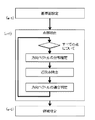
- FIG. 2 is a diagram showing an example of the processing flow of the map creating apparatus according to Embodiment 1 of the present invention. This figure also corresponds to a functional block diagram of the map creation device according to the first embodiment.
- 1 is a mobile measurement vehicle
- 2 is a data processing device
- 11 is a laser measurement device
- 12 is an IMU (Inertial Measurement Unit)
- 13 is a GPS (Global Positioning System) receiver
- 14 is an external storage.
- 15 is a PC (control device)
- 21 is a PC (Personal Computer)
- 22 is an external storage device
- 23 is an input device (mouse, keyboard)
- 24 is a display
- 25 is a printer.
- the mobile measurement vehicle 1 has the following devices mounted on the vehicle, and acquires measurement data while traveling.
- the laser measuring device 11 is a device that measures the distance and direction to a target by irradiating laser light in each direction and observing reflected light.
- the IMU 12 is a device that measures a change in posture of a vehicle using the law of inertia.
- the GPS receiver 13 is a device that receives radio waves from a satellite and measures the absolute position of the vehicle.
- the external storage device 14 stores the measurement data of each device in association with the time.
- the PC (control device) 15 controls the laser measurement device 11, the IMU 12, and the GPS receiver 13 and stores measurement data in the external storage device 14. It can be configured using a personal computer.
- the data processing device 2 is a device that processes the measurement data acquired by the mobile measurement vehicle and generates a map. It consists of the following devices.
- a PC (personal computer) 21 includes a central processing unit (CPU) and a main storage device, and performs data processing by executing software prepared in advance.
- the external storage device 22 stores the measurement data acquired by the mobile measurement vehicle 1 in this device, and performs data processing by reading it from the PC 21.
- the mobile measurement vehicle 1 and the data processing device 2 are each provided with the external storage devices 14 and 22, but the external storage device 14 of the mobile measurement vehicle 1 is removed and the PC 21 of the data processing device 2. May be used as an external storage device 22, or the mobile measurement vehicle 1 and the data processing device 2 may be connected to a network to copy data. Map information generated as a result of data processing is also stored in this device.
- the input device 23 includes a mouse, a keyboard, and the like, and inputs user instructions regarding map creation.
- the display 24 displays measurement data and created map data on the screen.
- the printer 25 prints the created map data.
- the laser measurement device 11 irradiates laser light in various directions while continuously rotating the laser irradiation device until the laser light is reflected back to the target and returned.
- the distance and direction to the reflection point are calculated by measuring the time.
- the position (x, y, z) in the relative space is calculated based on the distance and direction.
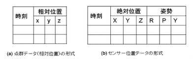
- the format of the measurement data obtained is a combination of the time of laser irradiation and the position (x, y, z) in the relative space.
- the relative space is a three-dimensional orthogonal coordinate with the position of the laser measuring device 11 as the origin.
- the x axis, the y axis, and the z axis are respectively defined as a right direction with respect to the vehicle traveling direction, a vehicle traveling direction, and an upward direction with respect to the vehicle traveling direction.
- (B) Sensor position acquisition The absolute position of the mobile measurement vehicle 1 is acquired by the GPS receiver 13 every 0.1 seconds, for example, and recorded in association with the time.
- the GPS receiver 13 information on latitude, longitude, and altitude can be obtained. In this embodiment, this is used as an origin at a certain point determined by ENU (East, North, Up) coordinates (latitude, longitude, altitude, (X-axis is east, Y-axis is north, and Z-axis is zenith direction).
- the attitude of the vehicle 1 at each time is measured based on the output of the IMU 12, and similarly recorded in association with the time.
- the posture of the vehicle is expressed by a set of three angles of roll (R), pitch (P), and yaw (Y).
- the roll is an angle of rotation about the axis in the traveling direction (y axis)
- the pitch is the angle of rotation about the axis in the right direction (x axis) with respect to the traveling direction
- the yaw is upward with respect to the traveling direction
- the angle of rotation about the axis (z-axis).
- FIG. 3B shows an example of the sensor position data format. The processing so far is performed in the mobile measurement vehicle 1, and the obtained point cloud data (relative position) and sensor position data are stored in the external storage device 14 of the mobile measurement vehicle 1.
- (C) Absolute Position Calculation The processing from here is processing in the data processing device 2.
- the point cloud data (relative position) and sensor position data obtained above are transferred from the external storage device 14 of the mobile measurement vehicle 1 to the external storage device 22 of the data processing device 2.
- the relative coordinates of the point cloud data are converted into absolute coordinates using the sensor position data by a program operating on the PC 21.
- the process of converting the relative coordinates (x, y, z) of the point measured at time t into absolute coordinates (X, Y, Z) follows the following equation.
- R is a rotation matrix that can be calculated from the attitude data Rt, Pt, and Yt of the sensor at time t by a known calculation formula
- T is the following when the position data of the sensor at time t is Xt, Yt, and Zt.
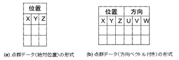
- Fig. 4 (a) shows an example of the format of the obtained point cloud data (absolute position).
- R is the same rotation matrix used in the absolute position calculation
- (x, y, z) is the relative coordinates of the point measured at time t.
- the obtained direction vector is stored as attribute information of each point constituting the point cloud data.
- FIG. 4B shows an example of the format of the obtained point cloud data (with direction vector).
- FIG. 5 shows the flow of area detection processing.
- FIG. 5 also corresponds to a functional block diagram obtained by further subdividing the area detecting means of the map creating apparatus according to the first embodiment.
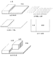
- FIG. 6A shows an example of a feature to be measured.
- the measurement target is divided into a sidewalk area and a roadway area. Since the relative height of the sidewalk area and the roadway area with respect to the sensor installed in the moving vehicle is substantially constant, the values z0 and z1 are set in advance.
- the rotation matrix R and the translation vector T at a certain time when the vicinity of the region is measured and applying the (Equation 1) to the relative coordinates z0 and z1, the respective Z coordinates Z0 and Z1 can be calculated.
- FIG. 6 (b) illustrates an example of point cloud data obtained by measuring the features in FIG. 6 (a). Since the points that make up the sidewalk area and the roadway area are assumed to be near the reference plane of the sidewalk area and the reference plane of the roadway area, a point cloud within a certain distance from each reference plane is extracted to form each area. Point cloud.
- each point is considered as a two-dimensional point cloud defined by the X coordinate and the Y coordinate. Find the polygon that encloses the group along its contour. This is the area to be obtained. Thereby, as shown in FIG.6 (c), a sidewalk area
- FIG. 6E shows an example when the vehicle is stopped on the roadway.
- points in the vicinity of the reference plane of the sidewalk among points constituting the vehicle are extracted as points constituting the sidewalk region.
- the region estimation result is such that the sidewalk protrudes from the roadway. In order to avoid this, the following processing is performed.
- the laser measurement device 11 mounted on the mobile measurement vehicle 1 in this embodiment can irradiate laser in almost all directions. Then, when the measurement is performed while running, the laser is irradiated from the front and rear to substantially the same point.
- the point cloud data (with direction vector) is examined to find neighboring points at almost the same position.
- the distribution of direction vectors of neighboring points depends on the orientation of the surface to which this point belongs and the sensor position. That is, when the laser is irradiated from the front and rear as in a sidewalk or a roadway, the direction vectors of the points constituting the surface are mixed forward and backward. However, the direction vector of a point belonging to a backward-facing surface such as the rear surface of the vehicle is only forward-facing.
- the direction vector distribution is estimated based on the direction of the reference plane and the sensor position, and only the points whose neighboring direction direction vector distribution matches the estimated direction vector distribution are extracted. To do. Specifically, the above point cloud extraction process is expanded as follows.
- the locus of the estimated direction vector can be obtained.
- the movement locus of the sensor is a straight line.
- the locus of the estimated direction vector becomes an arc.
- the locus of the estimated direction vector is expressed by a start direction vector and an end direction vector.
- Neighbor point extraction A point within a predetermined distance from a candidate point is extracted and set as a neighbor point. (Neighboring points include candidate points.)
- the locus of the direction vector of the neighboring points is obtained. This is realized, for example, by obtaining a range in which the direction vector exists in an arc formed by the locus of the estimated direction vector previously associated.
- the length of the estimated direction vector trajectory is compared with the length of the direction vector trajectory of the neighboring points, and if the ratio is within a predetermined range, it is determined that it is suitable. In this way, the points that make up the back and front of the vehicle do not match the distribution of the direction vector of the roadway and sidewalk, so they are not included in the extracted points and can correctly extract the sidewalk and roadway. it can.
- FIG. 6D is an example of a drawing result.
- the drawing apparatus is configured as described above. According to this configuration, a reference plane is set in a three-dimensional space, points whose positions are close to the reference plane and the direction vector distribution matches the direction of the reference plane are extracted, and a region is detected based on the distribution. Therefore, even if the operator does not specify the shape of the feature in detail, a map can be created by a simple operation, and an accurate map can be generated without detecting an erroneous area from points belonging to different planes. Has the effect of becoming possible.
- FIG. FIG. 1 is a diagram showing a configuration example of a map creating apparatus according to Embodiment 2 of the present invention, which is the same as the configuration example in Embodiment 1.
- 2 and 8 are diagrams showing an example of the processing flow of the map creating apparatus according to the second embodiment of the present invention. Of these, FIG. 2 is the same as the example of the processing flow in the first embodiment. This also corresponds to the functional block diagram of the map creation device according to Embodiment 2 of the present invention.
- FIG. 8 also corresponds to a functional block diagram obtained by further subdividing the area detecting means of the map creating apparatus according to the second embodiment.
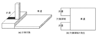
- FIG. 7A schematically shows an example of a measurement target.
- there are structures such as street trees on the sidewalk.
- an area where the laser does not reach is generated on the sidewalk behind the street tree as shown in the figure.
- a defective region as shown in FIG. 7B is generated.
- the second embodiment is a form for avoiding the occurrence of such a defective region.
- (E-1) Reference plane setting a reference plane for determination is defined. It is desirable to define this reference plane so that it is as close as possible to the region to be detected and the inclination with respect to the region plane is as small as possible. For example, if a sidewalk area is to be detected, it is better to define a horizontal surface near the ground.
- the range of the reference plane corresponds to the range of the map to be created. If a rectangular map is to be generated, it is preferable that the rectangle has a vertical side that matches the north-south direction and a horizontal side that matches the east-west direction.
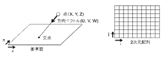
- the reference plane defined in (e-1) is divided into, for example, meshes with an interval of 5 cm. If the reference plane is 10 m in length and 5 m in width, the reference plane is divided into 200, 100 in length and 20000 meshes in total.
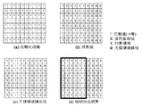
- a two-dimensional array corresponding to the mesh structure is secured in the main storage device and initialized. For example, ⁇ 1 or the like is set as the initial value (see FIG. 10A). Further, the following processing is performed for each point constituting the generated point group.
- the distance d is equal to or greater than th1 but smaller than another predetermined value th2, it is determined that the area is not a target such as a roadway, and a label 0 is attached.
- the distance d is greater than or equal to th2, it is not a point near the road surface such as a sidewalk or a roadway, so it is determined that the area may be a missing area because it is reflected by a structure such as a roadside tree, and the label 9 is (See FIG. 10B).
- (E-3) Missing Region Compensation A mesh with label 9 in the two-dimensional array is a candidate for the missing region.
- the mesh of label 9 adjacent to the mesh of label 1 is determined as a sidewalk region, and label 9 is changed to label 1. This process is repeated several times.
- the obtained result is shown in FIG.
- the defect area is eliminated.
- the mesh in which the label 9 remains is considered to be a defective area generated on the roadway by another structure. Since this mesh is not adjacent to the mesh of label 1, it is not complemented. In this way, the label 1 can be attached only to the mesh estimated as the sidewalk.
- FIG. 10D when the contour of the area formed by the mesh with the label 1 is obtained, this becomes the sidewalk area.
- the map creating apparatus is configured as described above.
- the area detection unit sets a reference plane in the three-dimensional space, projects the points on the set reference plane in the direction of the direction vector from the points constituting the point group, and projects the reference plane onto the reference plane. Since the missing area is extracted from the result and complemented, and the area is detected based on the result, the area can be detected correctly even if the point cloud data is missing, and an accurate map is generated by simple operations. There is an effect that it becomes possible.
- the map creation apparatus and map creation method according to the present invention can be applied to an apparatus for creating a map by measuring the position and shape of features around a road.
- 1 mobile measuring vehicle 2 data processing device, 11 laser measuring device, 12 IMU, 13 GPS receiver, 14 external storage device, 15 PC, 21 PC, 22 external storage device, 23 input device, 24 display, 25 printer
Landscapes
- Engineering & Computer Science (AREA)
- Physics & Mathematics (AREA)
- General Physics & Mathematics (AREA)
- Theoretical Computer Science (AREA)
- Remote Sensing (AREA)
- Radar, Positioning & Navigation (AREA)
- Computer Vision & Pattern Recognition (AREA)
- Geometry (AREA)
- Software Systems (AREA)
- Electromagnetism (AREA)
- Optics & Photonics (AREA)
- Computer Graphics (AREA)
- Mathematical Physics (AREA)
- Business, Economics & Management (AREA)
- Educational Administration (AREA)
- Educational Technology (AREA)
- Computer Networks & Wireless Communication (AREA)
- Multimedia (AREA)
- Length Measuring Devices By Optical Means (AREA)
- Processing Or Creating Images (AREA)
- Traffic Control Systems (AREA)
Abstract
Priority Applications (5)
| Application Number | Priority Date | Filing Date | Title |
|---|---|---|---|
| US16/070,755 US11250622B2 (en) | 2016-03-07 | 2016-03-07 | Map creation system and map creation method |
| PCT/JP2016/056925 WO2017154061A1 (fr) | 2016-03-07 | 2016-03-07 | Dispositif d'élaboration de carte et procédé d'élaboration de carte |
| AU2016396487A AU2016396487B2 (en) | 2016-03-07 | 2016-03-07 | Map creation system and map creation method |
| JP2018500747A JP6320664B2 (ja) | 2016-03-07 | 2016-03-07 | 地図作成装置および地図作成方法 |
| EP16893393.5A EP3404358B1 (fr) | 2016-03-07 | 2016-03-07 | Dispositif d'élaboration de carte et procédé d'élaboration de carte |
Applications Claiming Priority (1)
| Application Number | Priority Date | Filing Date | Title |
|---|---|---|---|
| PCT/JP2016/056925 WO2017154061A1 (fr) | 2016-03-07 | 2016-03-07 | Dispositif d'élaboration de carte et procédé d'élaboration de carte |
Publications (1)
| Publication Number | Publication Date |
|---|---|
| WO2017154061A1 true WO2017154061A1 (fr) | 2017-09-14 |
Family
ID=59790163
Family Applications (1)
| Application Number | Title | Priority Date | Filing Date |
|---|---|---|---|
| PCT/JP2016/056925 Ceased WO2017154061A1 (fr) | 2016-03-07 | 2016-03-07 | Dispositif d'élaboration de carte et procédé d'élaboration de carte |
Country Status (5)
| Country | Link |
|---|---|
| US (1) | US11250622B2 (fr) |
| EP (1) | EP3404358B1 (fr) |
| JP (1) | JP6320664B2 (fr) |
| AU (1) | AU2016396487B2 (fr) |
| WO (1) | WO2017154061A1 (fr) |
Cited By (5)
| Publication number | Priority date | Publication date | Assignee | Title |
|---|---|---|---|---|
| CN111462275A (zh) * | 2019-01-22 | 2020-07-28 | 北京京东尚科信息技术有限公司 | 一种基于激光点云的地图生产方法和装置 |
| CN112285737A (zh) * | 2020-10-23 | 2021-01-29 | 深圳无境智能机器人有限公司 | 一种可移动的道路特征测绘系统 |
| US11204243B2 (en) * | 2017-02-28 | 2021-12-21 | Topcon Corporation | Point cloud data extraction method and point cloud data extraction device |
| WO2022239350A1 (fr) * | 2021-05-13 | 2022-11-17 | 日立Astemo株式会社 | Dispositif de génération de carte/d'estimation d'autoposition |
| US11585665B2 (en) | 2017-11-30 | 2023-02-21 | Mitsubishi Electric Corporation | Three-dimensional map generation system, three-dimensional map generation method, and computer readable medium |
Families Citing this family (6)
| Publication number | Priority date | Publication date | Assignee | Title |
|---|---|---|---|---|
| US11370422B2 (en) * | 2015-02-12 | 2022-06-28 | Honda Research Institute Europe Gmbh | Method and system in a vehicle for improving prediction results of an advantageous driver assistant system |
| KR102063534B1 (ko) * | 2017-11-30 | 2020-01-09 | 주식회사 모빌테크 | 라이다를 이용한 지도 생성 방법 |
| WO2021231265A1 (fr) | 2020-05-11 | 2021-11-18 | Cognex Corporation | Procédés et appareil de génération d'histogrammes en nuages de points |
| US11810370B2 (en) * | 2021-06-30 | 2023-11-07 | Zoox, Inc. | Techniques for identifying curbs |
| CN117173420A (zh) * | 2022-05-25 | 2023-12-05 | 北京初速度科技有限公司 | 一种路面标线的矢量化方法、装置、地图制作系统及介质 |
| US20250216207A1 (en) * | 2024-01-02 | 2025-07-03 | Gm Cruise Holdings Llc | Combined walking and driving routes for autonomous vehicle rides |
Citations (2)
| Publication number | Priority date | Publication date | Assignee | Title |
|---|---|---|---|---|
| JP2009204615A (ja) | 2007-02-16 | 2009-09-10 | Mitsubishi Electric Corp | 道路地物計測装置、地物識別装置、道路地物計測方法、道路地物計測プログラム、計測装置、計測方法、計測端末装置、計測サーバ装置、作図装置、作図方法、作図プログラムおよび作図データ |
| JP2010533282A (ja) * | 2007-06-08 | 2010-10-21 | テレ アトラス ベスローテン フエンノートシャップ | 多視点パノラマを生成する方法及び装置 |
Family Cites Families (4)
| Publication number | Priority date | Publication date | Assignee | Title |
|---|---|---|---|---|
| US8364334B2 (en) * | 2008-10-30 | 2013-01-29 | Honeywell International Inc. | System and method for navigating an autonomous vehicle using laser detection and ranging |
| US9740200B2 (en) * | 2015-12-30 | 2017-08-22 | Unmanned Innovation, Inc. | Unmanned aerial vehicle inspection system |
| US11203425B2 (en) * | 2016-06-30 | 2021-12-21 | Skydio, Inc. | Unmanned aerial vehicle inspection system |
| JP6913164B2 (ja) * | 2016-11-11 | 2021-08-04 | マジック リープ, インコーポレイテッドMagic Leap,Inc. | 完全な顔画像の眼球周囲およびオーディオ合成 |
-
2016
- 2016-03-07 EP EP16893393.5A patent/EP3404358B1/fr not_active Not-in-force
- 2016-03-07 WO PCT/JP2016/056925 patent/WO2017154061A1/fr not_active Ceased
- 2016-03-07 JP JP2018500747A patent/JP6320664B2/ja not_active Expired - Fee Related
- 2016-03-07 US US16/070,755 patent/US11250622B2/en not_active Expired - Fee Related
- 2016-03-07 AU AU2016396487A patent/AU2016396487B2/en not_active Ceased
Patent Citations (2)
| Publication number | Priority date | Publication date | Assignee | Title |
|---|---|---|---|---|
| JP2009204615A (ja) | 2007-02-16 | 2009-09-10 | Mitsubishi Electric Corp | 道路地物計測装置、地物識別装置、道路地物計測方法、道路地物計測プログラム、計測装置、計測方法、計測端末装置、計測サーバ装置、作図装置、作図方法、作図プログラムおよび作図データ |
| JP2010533282A (ja) * | 2007-06-08 | 2010-10-21 | テレ アトラス ベスローテン フエンノートシャップ | 多視点パノラマを生成する方法及び装置 |
Non-Patent Citations (2)
| Title |
|---|
| PREVITALI, M.; M. SCAIONI; L. BARAZZETTI; R. BRUMANA: "A Flexible Methodology for Outdoor/indoor Building Reconstruction from Occluded Point Clouds", ISPRS ANNALS OF PHOTOGRAMMETRY, REMOTE SENSING AND SPATIAL INFORMATION SCIENCES, vol. II-3, 2014, pages 119 - 26 |
| See also references of EP3404358A4 |
Cited By (8)
| Publication number | Priority date | Publication date | Assignee | Title |
|---|---|---|---|---|
| US11204243B2 (en) * | 2017-02-28 | 2021-12-21 | Topcon Corporation | Point cloud data extraction method and point cloud data extraction device |
| US11585665B2 (en) | 2017-11-30 | 2023-02-21 | Mitsubishi Electric Corporation | Three-dimensional map generation system, three-dimensional map generation method, and computer readable medium |
| CN111462275A (zh) * | 2019-01-22 | 2020-07-28 | 北京京东尚科信息技术有限公司 | 一种基于激光点云的地图生产方法和装置 |
| CN111462275B (zh) * | 2019-01-22 | 2024-03-05 | 北京京东乾石科技有限公司 | 一种基于激光点云的地图生产方法和装置 |
| CN112285737A (zh) * | 2020-10-23 | 2021-01-29 | 深圳无境智能机器人有限公司 | 一种可移动的道路特征测绘系统 |
| WO2022239350A1 (fr) * | 2021-05-13 | 2022-11-17 | 日立Astemo株式会社 | Dispositif de génération de carte/d'estimation d'autoposition |
| JP2022175366A (ja) * | 2021-05-13 | 2022-11-25 | 日立Astemo株式会社 | 地図生成・自己位置推定装置 |
| JP7561683B2 (ja) | 2021-05-13 | 2024-10-04 | 日立Astemo株式会社 | 地図生成・自己位置推定装置 |
Also Published As
| Publication number | Publication date |
|---|---|
| US11250622B2 (en) | 2022-02-15 |
| US20210174579A1 (en) | 2021-06-10 |
| EP3404358A4 (fr) | 2019-01-16 |
| JPWO2017154061A1 (ja) | 2018-05-31 |
| EP3404358B1 (fr) | 2020-04-22 |
| JP6320664B2 (ja) | 2018-05-09 |
| EP3404358A1 (fr) | 2018-11-21 |
| AU2016396487B2 (en) | 2019-01-24 |
| AU2016396487A1 (en) | 2018-08-16 |
Similar Documents
| Publication | Publication Date | Title |
|---|---|---|
| JP6320664B2 (ja) | 地図作成装置および地図作成方法 | |
| US8625851B2 (en) | Measurement apparatus, measurement method, and feature identification apparatus | |
| JP5593177B2 (ja) | 点群位置データ処理装置、点群位置データ処理方法、点群位置データ処理システム、および点群位置データ処理プログラム | |
| JP6656886B2 (ja) | 情報処理装置、制御方法、プログラム及び記憶媒体 | |
| US20090154793A1 (en) | Digital photogrammetric method and apparatus using intergrated modeling of different types of sensors | |
| JP5762131B2 (ja) | キャリブレーション装置、キャリブレーション装置のキャリブレーション方法およびキャリブレーションプログラム | |
| KR101252680B1 (ko) | 디지털 항공이미지를 이용한 영상도화시스템 | |
| JP6910511B2 (ja) | レーザ計測方法、レーザ計測用標識、及び座標算出プログラム | |
| CN107917699B (zh) | 一种用于提高山区地貌倾斜摄影测量空三质量的方法 | |
| JP6745169B2 (ja) | レーザ計測システム及びレーザ計測方法 | |
| JP5814620B2 (ja) | 位置補正データ生成装置、位置標定装置、位置補正データ生成装置の位置補正データ生成方法、位置標定装置の位置標定方法、位置補正データ生成プログラムおよび位置標定プログラム | |
| Maboudi et al. | Evaluation of indoor mobile mapping systems | |
| KR101585203B1 (ko) | 항공 사진을 이용한 3차원 모델 제작시 수치표고모형을 이용하여 건물의 높이를 자동으로 추출하는 시스템 | |
| JP4852006B2 (ja) | 空間情報データベース生成装置及び空間情報データベース生成プログラム | |
| JP7682607B2 (ja) | 情報処理装置、制御方法、プログラム及び記憶媒体 | |
| Blaser et al. | Centimetre-accuracy in forests and urban canyons–combining a high-performance image-based mobile mapping backpack with new georeferencing methods | |
| JP2022066276A (ja) | 情報処理装置、制御方法、プログラム及び記憶媒体 | |
| JP7020418B2 (ja) | 情報処理装置、情報処理方法、およびプログラム | |
| Mutiarasari et al. | 3D Building models development based on data fusion–current status | |
| JP7562816B1 (ja) | 点群処理装置、点群処理方法及びプログラム | |
| JP7280028B2 (ja) | 地図画像投影装置及びプログラム | |
| Ye et al. | Photogrammetric Accuracy and Modeling of Rolling Shutter Cameras | |
| Ye et al. | RIGOROUS GEOMETRIC MODELLING OF 1960s ARGON SATELLITE IMAGES FOR ANTARCTIC ICE SHEET STEREO MAPPING. | |
| JP6535898B2 (ja) | 3次元モデル作成プログラム | |
| JP2004030460A (ja) | 画像処理方法、画像処理プログラム及びそれを記録した記録媒体 |
Legal Events
| Date | Code | Title | Description |
|---|---|---|---|
| ENP | Entry into the national phase |
Ref document number: 2018500747 Country of ref document: JP Kind code of ref document: A |
|
| ENP | Entry into the national phase |
Ref document number: 2016396487 Country of ref document: AU Date of ref document: 20160307 Kind code of ref document: A |
|
| WWE | Wipo information: entry into national phase |
Ref document number: 2016893393 Country of ref document: EP |
|
| ENP | Entry into the national phase |
Ref document number: 2016893393 Country of ref document: EP Effective date: 20180817 |
|
| NENP | Non-entry into the national phase |
Ref country code: DE |
|
| 121 | Ep: the epo has been informed by wipo that ep was designated in this application |
Ref document number: 16893393 Country of ref document: EP Kind code of ref document: A1 |