WO2017154062A1 - ガスクロマトグラフ質量分析装置 - Google Patents
ガスクロマトグラフ質量分析装置 Download PDFInfo
- Publication number
- WO2017154062A1 WO2017154062A1 PCT/JP2016/056928 JP2016056928W WO2017154062A1 WO 2017154062 A1 WO2017154062 A1 WO 2017154062A1 JP 2016056928 W JP2016056928 W JP 2016056928W WO 2017154062 A1 WO2017154062 A1 WO 2017154062A1
- Authority
- WO
- WIPO (PCT)
- Prior art keywords
- ionization
- analysis
- unit
- compound
- mass spectrometer
- Prior art date
- Legal status (The legal status is an assumption and is not a legal conclusion. Google has not performed a legal analysis and makes no representation as to the accuracy of the status listed.)
- Ceased
Links
Images



Classifications
-
- G—PHYSICS
- G01—MEASURING; TESTING
- G01N—INVESTIGATING OR ANALYSING MATERIALS BY DETERMINING THEIR CHEMICAL OR PHYSICAL PROPERTIES
- G01N30/00—Investigating or analysing materials by separation into components using adsorption, absorption or similar phenomena or using ion-exchange, e.g. chromatography or field flow fractionation
- G01N30/02—Column chromatography
- G01N30/62—Detectors specially adapted therefor
- G01N30/72—Mass spectrometers
- G01N30/7206—Mass spectrometers interfaced to gas chromatograph
-
- G—PHYSICS
- G01—MEASURING; TESTING
- G01N—INVESTIGATING OR ANALYSING MATERIALS BY DETERMINING THEIR CHEMICAL OR PHYSICAL PROPERTIES
- G01N27/00—Investigating or analysing materials by the use of electric, electrochemical, or magnetic means
- G01N27/62—Investigating or analysing materials by the use of electric, electrochemical, or magnetic means by investigating the ionisation of gases, e.g. aerosols; by investigating electric discharges, e.g. emission of cathode
- G01N27/622—Ion mobility spectrometry
- G01N27/623—Ion mobility spectrometry combined with mass spectrometry
-
- G—PHYSICS
- G01—MEASURING; TESTING
- G01N—INVESTIGATING OR ANALYSING MATERIALS BY DETERMINING THEIR CHEMICAL OR PHYSICAL PROPERTIES
- G01N30/00—Investigating or analysing materials by separation into components using adsorption, absorption or similar phenomena or using ion-exchange, e.g. chromatography or field flow fractionation
- G01N30/02—Column chromatography
- G01N30/62—Detectors specially adapted therefor
- G01N30/72—Mass spectrometers
-
- G—PHYSICS
- G01—MEASURING; TESTING
- G01N—INVESTIGATING OR ANALYSING MATERIALS BY DETERMINING THEIR CHEMICAL OR PHYSICAL PROPERTIES
- G01N30/00—Investigating or analysing materials by separation into components using adsorption, absorption or similar phenomena or using ion-exchange, e.g. chromatography or field flow fractionation
- G01N30/02—Column chromatography
- G01N2030/022—Column chromatography characterised by the kind of separation mechanism
- G01N2030/025—Gas chromatography
-
- G—PHYSICS
- G01—MEASURING; TESTING
- G01N—INVESTIGATING OR ANALYSING MATERIALS BY DETERMINING THEIR CHEMICAL OR PHYSICAL PROPERTIES
- G01N30/00—Investigating or analysing materials by separation into components using adsorption, absorption or similar phenomena or using ion-exchange, e.g. chromatography or field flow fractionation
- G01N30/02—Column chromatography
- G01N30/84—Preparation of the fraction to be distributed
- G01N2030/8447—Nebulising, aerosol formation or ionisation
- G01N2030/8452—Generation of electrically charged aerosols or ions
- G01N2030/8458—Generation of electrically charged aerosols or ions of ions or clusters of individual ions
Definitions
- the present invention relates to a gas chromatograph mass spectrometer, and more specifically, a gas chromatograph using an ion source capable of selectively performing ionization by electron ionization and ionization by chemical ionization as an ion source of the mass spectrometer.
- the present invention relates to a mass spectrometer.
- a gas chromatograph mass spectrometer (hereinafter abbreviated as “GC-MS”) using a mass spectrometer as a gas chromatograph detector, various compounds separated in time in a gas chromatograph column are generally used as an ion source for the mass spectrometer.
- the ions generated thereby are separated and detected according to the mass-to-charge ratio.
- an ion source it is necessary to ionize a compound contained in a gaseous sample, and generally, an electron ionization method (hereinafter referred to as “EI method”) or a chemical ionization method (hereinafter referred to as “CI method”).
- EI method electron ionization method
- CI method chemical ionization method
- the EI method thermal electrons generated by a filament are accelerated and brought into contact with component molecules in a sample gas. Then, electrons are emitted from the component molecules, and the molecules are ionized.
- ions generated by the EI method have excessive internal energy, fragment ions are easily generated by cleavage. For this reason, a component can be identified by collating the spectrum pattern of the mass spectrum in which various fragment ions are observed with a database (spectrum library). Moreover, based on the cleavage state, the structure of the original molecule can be examined.
- a reagent gas such as methane or isobutane is introduced into the ionization chamber, and thermal electrons are brought into contact with the reagent gas to generate reagent gas ions. Then, component molecules are introduced into the reagent gas ion atmosphere, and the component molecules are ionized by causing a chemical reaction.
- a mass spectrum in which molecular-related ions that are not cleaved is observed is obtained. Therefore, the ionization method is particularly useful for the purpose of obtaining information on the molecular weight of the target compound.
- the compound can be estimated from the obtained molecular weight.
- the CI method refers to a case where positive ions are generated based on the principle as described above, but there is also a method of generating negative ions based on a similar principle, which is called a negative chemical ionization method. Since this negative chemical ionization method is also a kind of CI method in a broad sense, in the following description, the CI method includes the negative chemical ionization method.
- the EI / CI can be switched between the EI method and the CI method only by switching the supply / stop of the reagent gas or changing the applied voltage to each electrode related to ionization. Dual-purpose ion sources are used (see Patent Documents 1 and 2).
- the conventional GC-MS has the following problems.
- a reagent gas is introduced into an ionization chamber having a relatively high sealing property, and the reagent gas is ionized by thermal electrons.
- the concentration of the reagent gas ions the higher the ionization efficiency. Therefore, the amount of the reagent gas introduced into the ionization chamber is usually large. Therefore, there is an excessive amount of reagent gas ions that do not contribute to ionization of component molecules in the ionization chamber.
- reagent gas ions are discharged into a chamber maintained in a vacuum atmosphere through an opening such as an ion injection hole formed in the ionization chamber, but a part thereof is disposed in the inner wall of the ionization chamber or in the ionization chamber. Adheres to repeller electrodes. As such a situation progresses, the state of the electric field formed inside the ionization chamber changes, and as a result, the ionization efficiency decreases or ions generated in the ionization chamber are appropriately ejected from the ion ejection holes. The loss of detection sensitivity and the reproducibility of measurement may occur.
- the ion source operates in comparison with a single mass spectrometer because various compounds separated in time by the GC column are sequentially detected by the mass spectrometer over time. Have a long time. For this reason, reagent gas ions adhering to the ionization chamber or the like increase, and the above-described problems are likely to occur.
- the present invention has been made to solve the above-mentioned problems, and the object of the present invention is to reduce the adhesion of excessive reagent gas ions to the ionization chamber and the like when performing ionization by the CI method.
- An object of the present invention is to provide a gas chromatograph mass spectrometer that is stable for a long period of time, that is, capable of maintaining highly sensitive and highly accurate measurement.
- the present invention includes an ionization chamber to which a sample gas is supplied, a thermoelectron generation unit that generates thermoelectrons, a reagent gas supply unit that supplies a reagent gas into the ionization chamber, Ionization by an electron ionization method in which thermoelectrons generated in the thermoelectron generator are brought into contact with components in the sample gas supplied into the ionization chamber to ionize the components, and in the thermoelectron generators Chemical ionization in which the generated thermoelectrons are brought into contact with the reagent gas supplied into the ionization chamber by the reagent gas supply unit to ionize the reagent gas and ionize components in the sample gas by the action of the reagent gas ions Chromatograph mass spectrometry using a mass spectrometer equipped with an ion source that can be switched between ionization by a gas method as a gas chromatograph detector In the location, a) Under ionization by
- a control information creation unit that determines a time range in which gas chromatograph mass spectrometry is to be performed, and creates control information including information indicating the time range; b) controlling the reagent gas supply unit to supply the reagent gas into the ionization chamber during the time range based on the control information, and setting the thermoelectron generation unit to generate thermoelectrons. Controlling and controlling the reagent gas supply unit to stop the supply of the reagent gas into the ionization chamber and / or controlling the thermoelectron generation unit to stop the generation of thermoelectrons outside the time range.
- the ion source of the mass spectrometer in the gas chromatograph mass spectrometer according to the present invention is an EI / CI combined ion source as described above.
- the configuration of the mass separator of the mass spectrometer is not particularly limited, and may be a single type mass spectrometer or a tandem mass spectrometer such as a triple quadrupole mass spectrometer.
- the analysis control unit first controls each unit such as the thermoelectron generation unit so as to perform ionization by the EI method in the ion source, and performs predetermined processing on the target sample. Perform gas chromatograph mass spectrometry over a range of time. As a result, a chromatogram over a predetermined time range is obtained. Further, when scan measurement is performed in the mass spectrometer, mass spectra in a predetermined mass-to-charge ratio range are sequentially obtained with time.
- the control information creation unit determines a time range in which the GC / MS measurement under the ionization by the CI method should be executed so that some or all of the plurality of peaks appearing in the obtained chromatogram are included. .
- This time range can be single or multiple.
- control information including information indicating the one or more time ranges is created.
- the analysis control unit controls the thermoelectron generation unit and the reagent gas supply unit based on the control information and performs ionization on the target sample by the CI method. Perform a GC / MS measurement at
- the reagent gas supply unit is controlled so as to supply the reagent gas into the ionization chamber, and the thermoelectron generation unit is controlled so that thermoelectrons are generated.
- the thermoelectron generation unit is controlled so that thermoelectrons are generated.
- reagent gas ions are generated in the ionization chamber in the time range, and the components in the sample gas introduced into the ionization chamber are ionized and subjected to mass spectrometry.
- the supply of the reagent gas into the ionization chamber is stopped, the generation of thermoelectrons is stopped, or both.
- Several modes can be considered as a method of determining the time range in the control information creation unit of the gas chromatograph mass spectrometer according to the present invention.
- the purpose of analysis is to identify a compound in a sample or to check whether a predetermined compound is included, it has been identified with high accuracy from a chromatogram or mass spectrum obtained by ionization by the EI method, or It is not necessary to perform a GC / MS measurement under ionization by the CI method for a compound whose presence or absence is confirmed.
- the GC / MS measurement under ionization by the CI method should be performed only for a compound (or a peak in which the compound is identified) whose compound identification result is uncertain or doubtful. That's fine.
- one embodiment of the gas chromatograph mass spectrometer is: A compound identification unit for identifying a compound corresponding to the peak based on the position information of the peak detected on the chromatogram or the mass spectrum information obtained by mass spectrometry at the position of the peak, and
- the control information creation unit extracts a compound to be subjected to gas chromatograph mass spectrometry under ionization by a chemical ionization method based on the identification result by the compound identification unit, and performs the time from the peak position corresponding to the compound. It can be set as the structure which determines a range.
- the control information creation unit determines an index value indicating the accuracy of identification obtained at the time of identification by the compound identification unit, whereby gas chromatograph mass spectrometry under ionization by a chemical ionization method is performed. It can be set as the structure which extracts the compound which should perform.
- the “index value indicating the accuracy of identification” is, for example, the similarity of spectrum patterns between an actually measured mass spectrum and a standard mass spectrum stored in a database. According to this configuration, the vicinity of the retention time of the peak corresponding to a compound with high uncertainty in the identification result can be automatically set as the time range.
- the apparatus further includes a result presentation unit that presents the identification result by the compound identification unit to a user, and the control information creation unit is configured to perform a chemical operation based on a user instruction for presentation of the result by the result presentation unit
- the control information creation unit is configured to perform a chemical operation based on a user instruction for presentation of the result by the result presentation unit
- the user designates an arbitrary peak on the chromatogram so that the time range in which the GC / MS measurement under ionization by the CI method should be performed is determined. Also good. For example, when it is desired to perform GC / MS measurement under ionization by the CI method for a large amount of compound in a sample regardless of the type of compound, it is convenient if the user can arbitrarily extract the compound by this method. is there.
- control information creation unit determines the time range by securing a predetermined time width before and after the peak retention time or peak start / end points corresponding to the extracted compound. It may be configured. This predetermined time width may be determined as a default, or may be set appropriately by the user.
- the control information creation unit does The time range may be determined as a part of the time range.
- the thermoelectron generation unit typically includes a filament and a power supply unit that supplies current to the filament. To stop the generation of thermoelectrons, the supply of current to the filament may be stopped. If the turn-off is repeated frequently, the filament is easily consumed. On the other hand, according to the above configuration, since the repetition of turning on / off the filament in a short time can be reduced, the consumption of the filament can be suppressed and its life can be extended.
- GC-MS continuous analysis is often performed while automatically exchanging a plurality of samples prepared in advance.
- the analysis conditions are set for each analysis. Therefore, for example, following the GC / MS measurement by the CI method for one sample, the same or another sample is analyzed. In some cases, GC / MS measurement by the EI method is performed.
- the analysis control unit is configured to perform another analysis in the case where another analysis is performed subsequent to the analysis of the one sample during or before the execution of the analysis under the ionization by the chemical ionization method for the one sample.
- the mass spectrometer at the latest
- the reagent gas supply unit is controlled so as to stop the supply of the reagent gas into the ionization chamber and / or the thermoelectron generation is stopped so as to stop the generation of the thermoelectrons. It may be configured to control the unit.
- the analysis control unit is set as one of the analysis conditions used in the next analysis during or before execution of analysis under ionization by the CI method for a certain sample. Recognize ionization methods.
- the next analysis is an analysis under ionization by the CI method, that is, in the case of an ionization method that does not require introduction of a reagent gas into the ionization chamber, the above-mentioned one sample is used in the mass spectrometer.
- the reagent gas supply unit when the analysis under the ionization by the CI method is completed, that is, when the ionization in the ion source is no longer necessary, the reagent gas supply unit, for example, quickly stops the supply of the reagent gas into the ionization chamber. To control. Further, when the analysis is a single analysis rather than the last analysis or the continuous analysis in the continuous analysis, there is no analysis subsequent to the analysis under the ionization by the CI method for the certain one sample. Even in this case, the analysis control unit quickly stops the supply of the reagent gas into the ionization chamber, for example, when the analysis under the ionization by the CI method on the certain sample is completed in the mass spectrometer. In this manner, the reagent gas supply unit is controlled.
- reagent gas ions are not generated in the ionization chamber after the ion source is no longer ionized by the CI method. Thereby, adhesion of reagent gas ions to the ionization chamber or the like can be further reduced.
- a single mass spectrometer equipped with an ion source capable of switching between the CI method and the EI method automatically performs a series of continuous analysis or multiple analyzes in order. When performing, the same effect can be acquired by performing control using the method of the said structure.
- the predetermined time including the retention time at which the mass analysis under the ionization by the CI method is required or the compound desired to be subjected to the mass analysis under the ionization appears. Only in the range reagent gas ions are generated in the ionization chamber. Thereby, the adhesion of reagent gas ions to the ionization chamber wall, repeller electrode, etc. can be reduced, and high detection sensitivity and high measurement reproducibility can be maintained over a long period of time. In addition, since maintenance such as cleaning of the ionization chamber can be reduced, the operating rate of the apparatus is increased, and the analysis cost can be reduced.
- the block diagram of the principal part of GC-MS which is one Example of this invention.
- FIG. 1 is a configuration diagram of a main part of the GC-MS of the present embodiment.
- a sample vaporizing chamber 11 is provided at the inlet end of the capillary column 13 disposed in the column oven 10, and a carrier gas such as He is sent to the capillary column 13 through the sample vaporizing chamber 11.
- the sample vaporizing chamber 11 is heated, measurement is started, and when a small amount of liquid sample is dropped into the sample vaporizing chamber 11 by the injector 12, the liquid sample is vaporized in a short time and rides on the carrier gas flow to become a capillary.
- Sent to the column 13 Various compounds contained in the sample are separated in the time direction while passing through the capillary column 13 and sequentially introduced into the mass spectrometer 2.
- an ion source 21, a lens electrode 22, a quadrupole mass filter 23, and an ion detector 24 are disposed in a vacuum chamber 20 that is evacuated by a vacuum pump (not shown).
- the ion source 21 is an EI / CI combined ion source, and includes an ionization chamber 211 into which a sample gas containing a compound is introduced, a filament 212 for generating thermoelectrons, and a reagent gas channel 213 provided with a valve 214 in the middle. , including.
- a predetermined current is supplied to the filament 212 from the filament power supply unit, the filament 212 is heated to generate thermoelectrons.
- thermoelectrons When ionization by the EI method is performed, a current is supplied to the filament 212 in a state where the valve 214 is closed (off). The thermoelectrons are accelerated by an electric field formed by a DC voltage applied to an electrode (not shown), the ionization chamber 211, the filament 212 itself, and the like, and enter the ionization chamber 211. Then, the compound in the sample gas introduced into the ionization chamber 211 is ionized by the contact with the thermoelectrons. On the other hand, when ionization by the CI method is performed, a current is supplied to the filament 212 with the valve 214 being opened (turned on).
- the reagent gas is supplied into the ionization chamber 211 through the reagent gas flow path 213, and the reagent gas ions are generated by contacting the reagent gas with the thermoelectrons.
- the reagent gas ions and the compound in the sample gas cause a chemical reaction, and ions derived from the compound are generated.
- the compound-derived ions generated in the ionization chamber 211 are removed from the ionization chamber 211 by the action of an electric field formed by a repeller electrode disposed in the ionization chamber 211. It is injected in the right direction.
- Ions exiting from the ionization chamber 211 are converged by the action of the electric field formed by the lens electrode 22 and sent to the quadrupole mass filter 23.
- Each of the four rod-shaped electrodes constituting the quadrupole mass filter 23 is applied with a predetermined voltage obtained by superimposing a DC voltage and a high-frequency voltage, and only ions having a mass-to-charge ratio m / z corresponding to the voltage are applied. Selectively passes through the filter 23 and reaches the ion detector 24.
- the ion detector 24 outputs a detection signal corresponding to the amount of incident ions, and this signal is digitized by an analog-to-digital converter (not shown) and input to the data processing unit 3.
- the data processing unit 3 includes, as functional blocks, a data storage unit 30, a chromatogram creation unit 31, a peak detection unit 32, a compound identification unit 33, a compound database 34, a CI control program automatic creation unit 35, and the like.
- a compound database standard mass spectra (fragment spectra obtained by the EI method) are stored in advance in association with a large number of compounds.
- the analysis control unit 4 controls each unit in order to perform measurement described later.
- the central control unit 5 to which the input unit 6 and the display unit 7 are connected gives instructions to the analysis control unit 4 and the data processing unit 3 in order to comprehensively control each unit according to a predetermined control program, and the analysis The result and the like are displayed on the display unit 7.
- the central control unit 5 and the data processing unit 3 use a general-purpose personal computer as a hardware resource, and realize the function by causing the computer to execute a predetermined control / processing program installed on the computer. It can be.
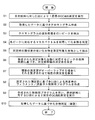
- FIG. 2 is a flowchart showing an example of characteristic measurement control and processing in the GC-MS of this embodiment
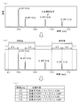
- FIG. 3 is an explanatory diagram of CI control program automatic creation processing.
- the case where it is desired to identify each compound in a target sample containing a large number of compounds will be described as an example.
- the GC / MS measurement under ionization by the EI method is performed on the target sample as the first GC / MS measurement (step S1). That is, when the user performs a predetermined operation from the input unit 6, the analysis control unit 4 that has received an instruction from the central control unit 5 sets the valve 214 and the filament power supply unit 25 so that ionization by the EI method is performed in the ion source 21. While controlling, other parts of the gas chromatograph 1 and the mass spectrometer 2 are controlled.
- the target sample is dropped from the injector 12 into the sample vaporization chamber 11, and various compounds in the sample are temporally separated while the vaporized target sample passes through the column 13, and the ions are sequentially ionized. Introduced into the source 21.
- the valve 214 is closed, and the sample-derived compound introduced into the ionization chamber 211 is ionized by contact with the thermoelectrons generated by the filament 212.
- the quadrupole mass filter 23 is driven to repeat scan measurement in a predetermined mass-to-charge ratio range. Thereby, as time elapses, data constituting a mass spectrum in a predetermined mass-to-charge ratio range is repeatedly input to the data processing unit 3, and this data is stored in the data storage unit 30.
- the chromatogram creation unit 31 creates a chromatogram (total ion chromatogram) based on the collected data (step S2).
- the peak detector 32 performs predetermined waveform processing on the created chromatogram to detect peaks, and acquires peak information such as the peak top time and peak start / end time of each peak (step S3). ).
- the compound identification unit 33 acquires, from the data storage unit 30, the measured mass spectrum obtained during the peak top time, that is, the retention time, for each peak detected in step S3, and is stored in the compound database 34.
- the compound is identified by collating with the mass spectrum (step S4). Specifically, the similarity of the spectrum pattern between the measured mass spectrum and the standard mass spectrum in the compound database 34 is calculated according to a predetermined algorithm, and the compound associated with the standard mass spectrum with the highest similarity is identified. Select as a candidate. Therefore, a candidate for identification of the compound is obtained together with the similarity for each peak on the chromatogram.
- the identification results (compounds and similarities) of all the peaks are displayed on the screen of the display unit 7 as a list of lists, for example.
- the user confirms the displayed identification result, and instructs the input unit 6 to perform the automatic creation process of the control program for performing the GC / MS measurement under the ionization by the CI method.
- the CI control program automatic creating unit 35 executes the following processing.
- a compound that satisfies a preset condition is extracted as a measurement target compound from the identification result obtained in step S4.
- This condition can be determined as appropriate, but here, the similarity calculated at the time of compound identification is not more than a predetermined threshold, that is, the spectrum pattern of the mass spectrum obtained under ionization by the EI method.
- a compound that has not been identified with sufficient accuracy is extracted as a measurement target compound (step S5).
- the threshold value for determining the similarity may be a default value, but may be arbitrarily set by the user.
- a predetermined retention time allowable width ⁇ T is secured before and after, respectively.
- a measurement window having a time width of 2 ⁇ T is set (step S6).
- the holding time allowable width ⁇ T may also be a default value, but may be arbitrarily set by the user.
- a part of the measurement window set for each peak overlaps, or when the difference in holding time between two adjacent peaks is not more than a predetermined tolerance (holding time difference tolerance) even if they do not overlap Is corrected to a wide measurement window by connecting a plurality of measurement windows for a plurality of adjacent peaks (step S7).
- FIG. 3 (a) is an example of a chromatogram obtained by the GC / MS measurement as described above.
- four peaks of A, B, C, and D are detected by the peak detection process, and their retention times (RT) are 10.0 min, 10.2 min, 10.8 min, 11. 3 minutes.
- RT retention times
- the compound identification for each of the four peaks the compound was identified with high accuracy for peak C, that is, with high similarity, whereas for the other three peaks A, B, and D, It is assumed that the compound was identified only with low similarity (no identification candidate was listed).
- the compounds that are identification candidates for the three peaks A, B, and D are the measurement target compounds.
- a measurement window having a time range of 11.0 min to 11.6 min including the peak D is set.
- the difference in retention time between peak A and peak B is 0.2 min, a part of the measurement windows overlaps. Therefore, the measurement window in the time range of 9.7 min to 10.5 min including both peak A and peak B is set by the processing in step S7.
- the peak A and the peak B A measurement window of a wide time range including both of the above is set.
- a control program for the GC / MS measurement under ionization by the CI method is created (step S8). That is, a control program is created so that the supply of the reagent gas is started at the start of the measurement window and the filament 212 is turned on, and the supply of the reagent gas is stopped and the filament 212 is turned off at the end of the measurement window.
- a control program is created so that the supply of the reagent gas is started at the start of the measurement window and the filament 212 is turned on, and the supply of the reagent gas is stopped and the filament 212 is turned off at the end of the measurement window.
- a control program is created in which the supply of the reagent gas is started at the time of 0 min and the filament 212 is turned on, and the supply of the reagent gas is stopped and the filament 212 is turned off at the time of 10.5 min and 11.6 min.
- the control program created in this way is sent to the central control unit 5 or the analysis control unit 4.
- the analysis control unit 4 controls the valve 214 and the filament power supply unit 25 according to the control program, while the GC / GC under ionization by the CI method is performed on the target sample.
- the MS measurement is performed as the second GC / MS measurement (step S9).
- the valve 214 is opened and the filament is opened in the time range of 9.7 to 10.5 min and 11.0 to 11.6 min.
- a current is supplied from the power supply unit 25 to the filament 212 to turn on the filament 212, and the ion source 21 performs ionization by the CI method.
- the sample gas containing the compound extracted as the measurement target compound in step S5 is introduced into the ion source 21, the compound is ionized and the ions are subjected to mass spectrometry.
- the valve 214 is closed and the filament 212 is turned off, reagent gas ions are not generated in the ionization chamber 211.
- the ion source 21 of the mass spectrometer 2 performs ionization only in a limited time range, and mass analysis is performed on the ions generated thereby.
- the mass spectrum data obtained in this way is stored in the data storage unit 30.
- the chromatogram creation unit 31 creates a chromatogram based on the obtained data, and the peak detection unit 32 detects a peak corresponding to the target compound on the chromatogram.
- the compound identification part 33 identifies the compound corresponding to the detected peak (step S10).
- the compound identification unit 33 calculates the molecular related ion peak of the target compound from the mass spectrum at the peak top position of the detected peak, typically a proton-added ion peak in which a proton is added to the target compound (or the target compound). Find the proton desorption ion peak from which the proton was desorbed, and estimate the molecular weight of the target compound from the mass-to-charge ratio of the peak. Then, by comparing this molecular weight with the compound database 34, it is determined whether or not the identification candidate estimated in step S4 is appropriate for the target compound. If there is a compound with higher accuracy than the identification candidate, the compound may be extracted as a new identification candidate.
- identification accuracy that is, identification reliability is extracted, but regardless of the identification accuracy, for example, the peak area value or peak top height value on the chromatogram is a predetermined threshold value. It is also possible to extract those exceeding the content, that is, those having a high content, or conversely, those having a low content.
- the user may be able to manually select the measurement target compound.
- the user designates an arbitrary peak or identification result on the input unit 6 on the list of peak identification results (compounds and similarities) displayed on the screen of the display unit 7 as a result of the process of step S4. It may be selected as a compound to be measured.
- the chromatogram may be displayed together, and the peak on the chromatogram may be instructed by a click operation or the like so that the identification result corresponding to the peak is selected as the measurement target compound.
- the supply of the reagent gas to the ionization chamber 211 is stopped and the filament 212 is turned off. Control may be performed. For example, if the filament 212 is turned off while the supply of the reagent gas is continued, the reagent gas is filled in the ionization chamber 211, but the reagent gas is not ionized and ionization by the CI method is not performed. Further, if the supply of the reagent gas is stopped while the filament 212 is turned on, no reagent gas ions are generated in the ionization chamber 211, so that ionization by the CI method is not performed.
- FIG. 4 is a configuration diagram of a main part of the GC-MS of this embodiment
- FIG. 5 is an explanatory diagram of a characteristic measurement control operation in the GC-MS.
- the same or corresponding components as those of the GC-MS shown in FIG. 1 are denoted by the same reference numerals, and description thereof is omitted unless particularly required.
- the gas chromatograph 1 includes an autosampler 14 that appropriately selects a plurality of samples prepared in advance and sucks them into the injector 12 as samples to be measured.
- the GC-MS of the present embodiment can automatically perform continuous analysis on a plurality of samples.
- the analysis control unit 4 includes a subsequent analysis ionization method determination unit 41 and a continuous analysis condition storage unit 42 as functional blocks.
- the user Prior to performing a continuous analysis, the user sets measurement conditions for each analysis during the continuous analysis from the input unit 6.
- the measurement conditions include selection of an ionization method, that is, information on whether to use an EI method, a CI method, or an NCI method.
- a method for executing the analysis under the CI method on the same sample following the analysis under the EI method may be set as a measurement condition for one analysis. it can.
- the measurement conditions set in this way are stored in files named measurement methods and stored in the continuous analysis condition storage unit 42. Of course, the same measurement method can be applied to multiple analyses.
- the analysis control unit 4 reads the measurement conditions stored in the measurement method in a predetermined order, and performs GC / MS measurement by controlling each unit according to the measurement conditions. For example, if the CI method is selected as the ionization method, the analysis control unit 4 opens so that the reagent gas is supplied into the ionization chamber 211 at the start of the analysis by the mass spectrometer 2, and the filament power supply unit 25 opens the filament. A current is supplied to 212 to light up the filament 212.
- the next analysis ionization method determination unit 41 reads the measurement conditions stored in the measurement method corresponding to the next analysis of the currently performed analysis, and determines whether the ionization method is the CI method or not. Determine whether it is legal.
- the ionization method of the analysis currently being performed is the CI method and the ionization method of the next analysis is the EI method, immediately after the analysis currently being performed in the mass spectrometer 2 is completed. For example, as soon as a predetermined analysis execution time has elapsed, the valve 214 is closed and the filament 212 is turned off so as to stop the supply of the reagent gas into the ionization chamber 211.
- the ionization method of analysis currently being carried out is the EI method and the ionization method of the next analysis is the CI method
- the next analysis is started in the mass spectrometer 2
- the valve 214 is opened and the filament 212 is turned on so that the supply of the reagent gas is started.
- the ionization method of analysis currently being performed is the CI method and the analysis is the last analysis in the continuous analysis, that is, when the next analysis is not set, the mass spectrometer is also used.
- the valve 214 is closed and the filament 212 is turned off so as to stop the supply of the reagent gas into the ionization chamber 211.
- continuous analysis is set so that n analyzes from analysis 1 to analysis n are performed in order.
- ionization by the CI method When ionization by the EI method is set in the analysis of, the reagent gas is ionized in the ionization chamber 211 from the time when the first analysis is started in the mass spectrometer 2 to the time when the second analysis is started. As soon as the second analysis is completed, the supply of the reagent gas is stopped. Further, as soon as the last analysis in the continuous analysis is completed, the supply of the reagent gas is stopped.
- the time during which the reagent gas ions are generated in the ionization chamber 211 can be more reliably suppressed, and the adhesion of the reagent gas ions to the inner wall surface of the ionization chamber 211 or the repeller electrode can be reduced. Can do.
- control as described above can be performed not only in a series of continuous analyzes but also when performing a single analysis set by the user in order according to a predetermined schedule.
Landscapes
- Physics & Mathematics (AREA)
- Chemical & Material Sciences (AREA)
- Health & Medical Sciences (AREA)
- Life Sciences & Earth Sciences (AREA)
- General Physics & Mathematics (AREA)
- Pathology (AREA)
- Immunology (AREA)
- Analytical Chemistry (AREA)
- Biochemistry (AREA)
- General Health & Medical Sciences (AREA)
- Spectroscopy & Molecular Physics (AREA)
- Chemical Kinetics & Catalysis (AREA)
- Electrochemistry (AREA)
- Molecular Biology (AREA)
- Other Investigation Or Analysis Of Materials By Electrical Means (AREA)
Abstract
Description
上述したようにCI法では比較的密閉性の高いイオン化室内に試薬ガスを導入し、該試薬ガスを熱電子によってイオン化する。通常、試薬ガスイオンの濃度が高いほうがイオン化効率は高いため、通常、イオン化室内に導入される試薬ガスの量は多い。そのため、イオン化室内には成分分子のイオン化に寄与しない過剰な量の試薬ガスイオンが存在する。こうした試薬ガスイオンの多くはイオン化室に形成されているイオン射出孔等の開口を通して真空雰囲気に保たれるチャンバ内に排出されるが、一部はイオン化室の内壁やイオン化室内に配置されているリペラ電極などに付着する。そうした状況が進行すると、イオン化室の内部に形成される電場の状態などが変化してしまい、その影響でイオン化効率が低下したり或いはイオン化室内で生成されたイオンが適切にイオン射出孔から射出されなくなったりして、検出感度の低下や測定の再現性の低下を引き起こすことがある。
a)前記イオン源で電子イオン化法によるイオン化を行い、目的試料に対し所定の時間範囲に亘るガスクロマトグラフ質量分析を実行することにより得られたクロマトグラムに基づいて、化学イオン化法によるイオン化の下でのガスクロマトグラフ質量分析を実行すべき時間範囲を決定し、その時間範囲を示す情報を含む制御情報を作成する制御情報作成部と、
b)前記制御情報に基づいて、前記時間範囲中には前記試薬ガスを前記イオン化室内に供給するように前記試薬ガス供給部を制御し且つ熱電子が生成されるように前記熱電子生成部を制御し、前記時間範囲外には前記イオン化室内への試薬ガスの供給を停止するように前記試薬ガス供給部を制御し及び/又は熱電子の生成を停止するように前記熱電子生成部を制御することで、前記イオン源で化学イオン化法によるイオン化を行い、前記目的試料に対してガスクロマトグラフ質量分析を実行する分析制御部と、
を備えることを特徴としている。
例えば分析目的が試料中の化合物の同定や所定の化合物が含まれるか否かの確認である場合、EI法によるイオン化を行うことで得られたクロマトグラムやマススペクトルから高い確度で同定された又は存在の有無が確認された化合物については、CI法によるイオン化の下でのGC/MS測定を実行する必要はない。換言すれば、化合物の同定結果が不確かであったりその結果に疑義があったりする化合物(又はその化合物が同定されているピーク)についてのみCI法によるイオン化の下でのGC/MS測定を実行すればよい。
前記クロマトグラム上で検出されるピークの位置情報又は該ピークの位置における質量分析で得られたマススペクトル情報に基づいてそのピークに対応する化合物を同定する化合物同定部と、をさらに備え、
前記制御情報作成部は、前記化合物同定部による同定結果に基づき、化学イオン化法によるイオン化の下でのガスクロマトグラフ質量分析を実行すべき化合物を抽出し、その化合物に対応するピークの位置から前記時間範囲を決定する構成とすることができる。
即ち、一つの態様として、前記制御情報作成部は、前記化合物同定部による同定の際に求まる同定の確度を示す指標値を判定することにより、化学イオン化法によるイオン化の下でのガスクロマトグラフ質量分析を実行すべき化合物を抽出する構成とすることができる。「同定の確度を示す指標値」とは例えば、実測のマススペクトルとデータベースに格納されている標準マススペクトルとのスペクトルパターンの類似度などである。
この構成によれば、同定結果の不確定性が高い化合物に対応するピークの保持時間の付近を時間範囲として自動的に設定することができる。
この構成によれば、例えば同定結果の不確定性が高くても重要度の低い化合物については抽出せず、逆に同定結果の確度は高くても重要度が高い化合物については敢えて抽出する等、ユーザーの判断に基づく化合物の取捨選択が可能である。
この構成では、試料中の化合物の数が多く、複数の化合物の保持時間が近接している場合に、それら複数の化合物の保持時間を含む幅広い時間範囲が設定される。熱電子生成部は典型的にはフィラメントと該フィラメントに電流を供給する電源部とから成り、熱電子の生成を停止するにはフィラメントへの電流の供給を停止すればよいが、フィラメントの点灯と消灯とが頻繁に繰り返されるとフィラメントが消耗し易くなる。これに対し、上記構成によれば、短時間の間におけるフィラメントの点灯・消灯の繰り返しを減らすことができるので、フィラメントの消耗を抑えその寿命を延ばすことができる。
前記分析制御部は、一つの試料に対する化学イオン化法によるイオン化の下での分析の実行中又は実行前に、該一つの試料の分析に引き続いて別の分析を実行する場合には該別の分析で用いられるイオン化法を認識し、該別の分析で用いられるイオン化法が電子イオン化法である場合又は前記一つの試料の分析に引き続いて実行される分析がない場合には、遅くとも前記質量分析装置において前記一つの試料の分析が終了した時点で前記イオン化室内への試薬ガスの供給を停止するように前記試薬ガス供給部を制御し及び/又は熱電子の生成を停止するように前記熱電子生成部を制御する構成とするよい。
なお、GC-MSに限らず、CI法とEI法とを切替え可能なイオン源を備えた単体の質量分析装置であっても自動的に一連の連続分析を行う場合や複数の分析を順番に行う場合に、上記構成の手法を利用した制御を行うことで、同様の効果を得ることができる。
まず、ステップS4で得られた同定結果の中で予め設定された条件を満たす化合物を測定対象化合物として抽出する。この条件とは適宜に定めることができるが、ここでは、化合物同定の際に算出された類似度が所定閾値以下であるもの、つまりはEI法によるイオン化の下で得られたマススペクトルのスペクトルパターンでは十分な確度で同定が行われなかった化合物を測定対象化合物として抽出する(ステップS5)。この類似度を判定する閾値はデフォルト値でもよいが、ユーザーが任意に設定できるようにしてもよい。
このような制御を行うことで、イオン化室211内で試薬ガスイオンが生成される時間をより確実に抑制し、イオン化室211の内壁面やリペラ電極などへの試薬ガスイオンの付着を軽減することができる。
10…カラムオーブン
11…試料気化室
12…インジェクタ
13…キャピラリカラム
14…オートサンプラ
2…質量分析装置
20…真空チャンバ
21…イオン源
211…イオン化室
212…フィラメント
213…試薬ガス流路
214…バルブ
22…レンズ電極
23…四重極マスフィルタ
24…イオン検出器
25…フィラメント電源部
3…データ処理部
30…データ格納部
30…中央制御部
31…クロマトグラム作成部
31…分析制御部
32…データ処理部
32…ピーク検出部
33…化合物同定部
34…化合物データベース
35…CI用制御プログラム自動作成部
4…分析制御部
41…次分析イオン化法判定部
42…連続分析条件記憶部
5…中央制御部
6…入力部
7…表示部
Claims (7)
- 試料ガスが供給されるイオン化室と、熱電子を生成する熱電子生成部と、前記イオン化室内に試薬ガスを供給する試薬ガス供給部と、を有し、前記熱電子生成部で生成された熱電子を前記イオン化室内に供給された試料ガス中の成分に接触させて該成分をイオン化する電子イオン化法によるイオン化と、前記熱電子生成部で生成された熱電子を、前記試薬ガス供給部により前記イオン化室内に供給された試薬ガスに接触させて該試薬ガスをイオン化し、その試薬ガスイオンの作用により試料ガス中の成分をイオン化する化学イオン化法によるイオン化と、を切り替えて行うことが可能なイオン源、を具備する質量分析装置をガスクロマトグラフの検出器として用いたガスクロマトグラフ質量分析装置において、
a)前記イオン源で電子イオン化法によるイオン化を行い、目的試料に対し所定の時間範囲に亘るガスクロマトグラフ質量分析を実行することにより得られたクロマトグラムに基づいて、化学イオン化法によるイオン化の下でのガスクロマトグラフ質量分析を実行すべき時間範囲を決定し、その時間範囲を示す情報を含む制御情報を作成する制御情報作成部と、
b)前記制御情報に基づいて、前記時間範囲中には前記試薬ガスを前記イオン化室内に供給するように前記試薬ガス供給部を制御し且つ熱電子が生成されるように前記熱電子生成部を制御し、前記時間範囲外には前記イオン化室内への試薬ガスの供給を停止するように前記試薬ガス供給部を制御し及び/又は熱電子の生成を停止するように前記熱電子生成部を制御することで、前記イオン源で化学イオン化法によるイオン化を行い、前記目的試料に対してガスクロマトグラフ質量分析を実行する分析制御部と、
を備えることを特徴とするガスクロマトグラフ質量分析装置。 - 請求項1に記載のガスクロマトグラフ質量分析装置であって、
前記クロマトグラム上で検出されるピークの位置情報又は該ピークの位置における質量分析で得られたマススペクトル情報に基づいてそのピークに対応する化合物を同定する化合物同定部と、をさらに備え、
前記制御情報作成部は、前記化合物同定部による同定結果に基づき、化学イオン化法によるイオン化の下でのガスクロマトグラフ質量分析を実行すべき化合物を抽出し、その化合物に対応するピークの位置から前記時間範囲を決定することを特徴とするガスクロマトグラフ質量分析装置。 - 請求項2に記載のガスクロマトグラフ質量分析装置であって、
前記制御情報作成部は、前記化合物同定部による同定の際に求まる同定の確度を示す指標値を判定することにより、化学イオン化法によるイオン化の下でのガスクロマトグラフ質量分析を実行すべき化合物を抽出することを特徴とするガスクロマトグラフ質量分析装置。 - 請求項2に記載のガスクロマトグラフ質量分析装置であって、
前記化合物同定部による同定結果をユーザーに提示する結果提示部をさらに備え、
前記制御情報作成部は、前記結果提示部による結果の提示に対するユーザーの指示に基づいて、化学イオン化法によるイオン化の下でのガスクロマトグラフ質量分析を実行すべき化合物を抽出することを特徴とするガスクロマトグラフ質量分析装置。 - 請求項2~4のいずれか1項に記載のガスクロマトグラフ質量分析装置であって、
前記制御情報作成部は、抽出された化合物に対応するピークの保持時間又はピークの開始点・終了点から前後に所定の時間幅を確保することで前記時間範囲を決定することを特徴とするガスクロマトグラフ質量分析装置。 - 請求項5に記載のガスクロマトグラフ質量分析装置であって、
前記制御情報作成部は、抽出された複数の化合物に対応する時間的に隣接するピークの保持時間の差が所定の時間幅よりも小さい場合、該ピークの間は前記時間範囲の一部として該時間範囲を決定することを特徴とするガスクロマトグラフ質量分析装置。 - 請求項1に記載のガスクロマトグラフ質量分析装置であって、
前記分析制御部は、一つの試料に対する化学イオン化法によるイオン化の下での分析の実行中又は実行前に、該一つの試料の分析に引き続いて別の分析を実行する場合には該別の分析で用いられるイオン化法を認識し、該別の分析で用いられるイオン化法が電子イオン化法である場合又は前記一つの試料の分析に引き続いて実行される分析がない場合には、遅くとも前記質量分析装置において前記一つの試料の分析が終了した時点で前記イオン化室内への試薬ガスの供給を停止するように前記試薬ガス供給部を制御し及び/又は熱電子の生成を停止するように前記熱電子生成部を制御することを特徴とするガスクロマトグラフ質量分析装置。
Priority Applications (6)
| Application Number | Priority Date | Filing Date | Title |
|---|---|---|---|
| US16/082,589 US10794878B2 (en) | 2016-03-07 | 2016-03-07 | Gas chromatograph mass spectrometer |
| JP2018503856A JP6493621B2 (ja) | 2016-03-07 | 2016-03-07 | ガスクロマトグラフ質量分析装置 |
| EP16893394.3A EP3428637A4 (en) | 2016-03-07 | 2016-03-07 | GAS CHROMATOGRAPH / MASS SPECTROMETER |
| SG11201807566RA SG11201807566RA (en) | 2016-03-07 | 2016-03-07 | Gas chromatograph mass spectrometer |
| CN201680083342.1A CN108780071B (zh) | 2016-03-07 | 2016-03-07 | 气相色谱质谱分析装置 |
| PCT/JP2016/056928 WO2017154062A1 (ja) | 2016-03-07 | 2016-03-07 | ガスクロマトグラフ質量分析装置 |
Applications Claiming Priority (1)
| Application Number | Priority Date | Filing Date | Title |
|---|---|---|---|
| PCT/JP2016/056928 WO2017154062A1 (ja) | 2016-03-07 | 2016-03-07 | ガスクロマトグラフ質量分析装置 |
Publications (1)
| Publication Number | Publication Date |
|---|---|
| WO2017154062A1 true WO2017154062A1 (ja) | 2017-09-14 |
Family
ID=59790246
Family Applications (1)
| Application Number | Title | Priority Date | Filing Date |
|---|---|---|---|
| PCT/JP2016/056928 Ceased WO2017154062A1 (ja) | 2016-03-07 | 2016-03-07 | ガスクロマトグラフ質量分析装置 |
Country Status (6)
| Country | Link |
|---|---|
| US (1) | US10794878B2 (ja) |
| EP (1) | EP3428637A4 (ja) |
| JP (1) | JP6493621B2 (ja) |
| CN (1) | CN108780071B (ja) |
| SG (1) | SG11201807566RA (ja) |
| WO (1) | WO2017154062A1 (ja) |
Cited By (2)
| Publication number | Priority date | Publication date | Assignee | Title |
|---|---|---|---|---|
| JP2019066338A (ja) * | 2017-10-02 | 2019-04-25 | 日本電子株式会社 | 質量分析データ処理装置、及び質量分析データ処理方法 |
| TWI669497B (zh) * | 2018-07-30 | 2019-08-21 | 日商三菱電機股份有限公司 | 氣體分析裝置及氣體分析方法 |
Families Citing this family (3)
| Publication number | Priority date | Publication date | Assignee | Title |
|---|---|---|---|---|
| US11474087B2 (en) * | 2016-12-20 | 2022-10-18 | Dh Technologies Development Pte. Ltd. | Automated expected retention time and optimal expected retention time window detection |
| JP6941650B2 (ja) * | 2019-09-20 | 2021-09-29 | ネッチ ゲレーテバウ ゲーエムベーハー | ガス分析装置、及びガス分析方法 |
| JP7495059B2 (ja) * | 2020-11-02 | 2024-06-04 | 株式会社島津製作所 | におい評価用ガス回収装置及びにおい評価方法並びににおい評価用試料調整装置 |
Citations (3)
| Publication number | Priority date | Publication date | Assignee | Title |
|---|---|---|---|---|
| JPH0589822A (ja) * | 1991-09-25 | 1993-04-09 | Jeol Ltd | 質量分析装置用イオン源 |
| JPH11307041A (ja) * | 1998-04-22 | 1999-11-05 | Shimadzu Corp | イオン化装置 |
| JP2009036739A (ja) * | 2007-08-06 | 2009-02-19 | Hitachi Ltd | 質量分析装置及び質量分析方法 |
Family Cites Families (5)
| Publication number | Priority date | Publication date | Assignee | Title |
|---|---|---|---|---|
| JP4596641B2 (ja) * | 2000-12-28 | 2010-12-08 | キヤノンアネルバ株式会社 | イオン付着質量分析の方法および装置 |
| US8299421B2 (en) | 2010-04-05 | 2012-10-30 | Agilent Technologies, Inc. | Low-pressure electron ionization and chemical ionization for mass spectrometry |
| US8378293B1 (en) * | 2011-09-09 | 2013-02-19 | Agilent Technologies, Inc. | In-situ conditioning in mass spectrometer systems |
| CN102969218A (zh) * | 2012-11-05 | 2013-03-13 | 聚光科技(杭州)股份有限公司 | 多通道混合电离源及其工作方法 |
| US10121644B2 (en) * | 2014-02-10 | 2018-11-06 | Shimadzu Corporation | Mass spectrometer and mass spectrometry method |
-
2016
- 2016-03-07 WO PCT/JP2016/056928 patent/WO2017154062A1/ja not_active Ceased
- 2016-03-07 US US16/082,589 patent/US10794878B2/en active Active
- 2016-03-07 CN CN201680083342.1A patent/CN108780071B/zh active Active
- 2016-03-07 JP JP2018503856A patent/JP6493621B2/ja active Active
- 2016-03-07 EP EP16893394.3A patent/EP3428637A4/en not_active Withdrawn
- 2016-03-07 SG SG11201807566RA patent/SG11201807566RA/en unknown
Patent Citations (3)
| Publication number | Priority date | Publication date | Assignee | Title |
|---|---|---|---|---|
| JPH0589822A (ja) * | 1991-09-25 | 1993-04-09 | Jeol Ltd | 質量分析装置用イオン源 |
| JPH11307041A (ja) * | 1998-04-22 | 1999-11-05 | Shimadzu Corp | イオン化装置 |
| JP2009036739A (ja) * | 2007-08-06 | 2009-02-19 | Hitachi Ltd | 質量分析装置及び質量分析方法 |
Non-Patent Citations (1)
| Title |
|---|
| See also references of EP3428637A4 * |
Cited By (3)
| Publication number | Priority date | Publication date | Assignee | Title |
|---|---|---|---|---|
| JP2019066338A (ja) * | 2017-10-02 | 2019-04-25 | 日本電子株式会社 | 質量分析データ処理装置、及び質量分析データ処理方法 |
| JP7105049B2 (ja) | 2017-10-02 | 2022-07-22 | 日本電子株式会社 | 質量分析データ処理装置、及び質量分析データ処理方法 |
| TWI669497B (zh) * | 2018-07-30 | 2019-08-21 | 日商三菱電機股份有限公司 | 氣體分析裝置及氣體分析方法 |
Also Published As
| Publication number | Publication date |
|---|---|
| US20190086372A1 (en) | 2019-03-21 |
| JPWO2017154062A1 (ja) | 2018-07-26 |
| US10794878B2 (en) | 2020-10-06 |
| SG11201807566RA (en) | 2018-10-30 |
| CN108780071B (zh) | 2021-06-08 |
| EP3428637A1 (en) | 2019-01-16 |
| CN108780071A (zh) | 2018-11-09 |
| EP3428637A4 (en) | 2019-03-20 |
| JP6493621B2 (ja) | 2019-04-03 |
Similar Documents
| Publication | Publication Date | Title |
|---|---|---|
| JP6493621B2 (ja) | ガスクロマトグラフ質量分析装置 | |
| US9514922B2 (en) | Mass analysis data processing apparatus | |
| CN104569234B (zh) | 串联四极型质谱仪 | |
| JP5273144B2 (ja) | 質量分析データ解析方法及び質量分析データ解析装置 | |
| US7985948B2 (en) | Systems and methods for analyzing substances using a mass spectrometer | |
| JP6460252B2 (ja) | 定性分析のための質量分析データ処理装置 | |
| US11408853B2 (en) | DM-SWATH acquisition to improve MSMS confidence | |
| US20140374583A1 (en) | Electron ionization (ei) utilizing different ei energies | |
| JP5900631B2 (ja) | 質量分析装置 | |
| JPWO2012124020A1 (ja) | 質量分析装置 | |
| US12031943B2 (en) | Ion analyzer | |
| JP2009129868A (ja) | 質量分析装置及びその調整方法 | |
| WO2015092862A1 (ja) | 質量分析装置及び質量分析方法 | |
| US10768151B2 (en) | Techniques for display and processing of mass spectral data | |
| JP6702501B2 (ja) | タンデム型質量分析装置及び該装置用プログラム | |
| JP4758862B2 (ja) | 質量分析方法及び装置 | |
| JP7070692B2 (ja) | 質量分析装置及び質量分析方法 | |
| JP4851273B2 (ja) | 質量分析方法および質量分析装置 | |
| US10008376B2 (en) | Methods and systems for selecting ions for ion fragmentation | |
| JP4801455B2 (ja) | 質量分析システム | |
| US20220187260A1 (en) | Agnostic Compound Elution Determination | |
| JP5747839B2 (ja) | クロマトグラフ質量分析用データ処理装置 | |
| JP5527438B2 (ja) | 質量分析装置 | |
| CN111052301B (zh) | 用以改进ms/ms动态范围的动态平衡时间计算 | |
| Ji | Using peak intensity and fragmentation patterns in peptide sequence identification (SQID): A Bayesian learning algorithm for tandem mass spectra |
Legal Events
| Date | Code | Title | Description |
|---|---|---|---|
| ENP | Entry into the national phase |
Ref document number: 2018503856 Country of ref document: JP Kind code of ref document: A |
|
| WWE | Wipo information: entry into national phase |
Ref document number: 11201807566R Country of ref document: SG |
|
| NENP | Non-entry into the national phase |
Ref country code: DE |
|
| WWE | Wipo information: entry into national phase |
Ref document number: 2016893394 Country of ref document: EP |
|
| ENP | Entry into the national phase |
Ref document number: 2016893394 Country of ref document: EP Effective date: 20181008 |
|
| 121 | Ep: the epo has been informed by wipo that ep was designated in this application |
Ref document number: 16893394 Country of ref document: EP Kind code of ref document: A1 |