WO2017154092A1 - Dispositif d'aide à la conduite, système d'aide à la conduite, et procédé d'aide à la conduite - Google Patents
Dispositif d'aide à la conduite, système d'aide à la conduite, et procédé d'aide à la conduite Download PDFInfo
- Publication number
- WO2017154092A1 WO2017154092A1 PCT/JP2016/057104 JP2016057104W WO2017154092A1 WO 2017154092 A1 WO2017154092 A1 WO 2017154092A1 JP 2016057104 W JP2016057104 W JP 2016057104W WO 2017154092 A1 WO2017154092 A1 WO 2017154092A1
- Authority
- WO
- WIPO (PCT)
- Prior art keywords
- vehicle
- driving
- mode
- driving support
- support
- Prior art date
- Legal status (The legal status is an assumption and is not a legal conclusion. Google has not performed a legal analysis and makes no representation as to the accuracy of the status listed.)
- Ceased
Links
Images




Classifications
-
- G—PHYSICS
- G01—MEASURING; TESTING
- G01C—MEASURING DISTANCES, LEVELS OR BEARINGS; SURVEYING; NAVIGATION; GYROSCOPIC INSTRUMENTS; PHOTOGRAMMETRY OR VIDEOGRAMMETRY
- G01C21/00—Navigation; Navigational instruments not provided for in groups G01C1/00 - G01C19/00
- G01C21/26—Navigation; Navigational instruments not provided for in groups G01C1/00 - G01C19/00 specially adapted for navigation in a road network
-
- G—PHYSICS
- G08—SIGNALLING
- G08G—TRAFFIC CONTROL SYSTEMS
- G08G1/00—Traffic control systems for road vehicles
-
- G—PHYSICS
- G08—SIGNALLING
- G08G—TRAFFIC CONTROL SYSTEMS
- G08G1/00—Traffic control systems for road vehicles
- G08G1/16—Anti-collision systems
Definitions
- the present invention relates to a technology that supports driving of a vehicle that performs automatic driving.
- the automatic driving device for a vehicle described in Patent Document 1 starts automatic traveling of the host vehicle with a stoppable area where the vehicle can be retreated as a destination for automatic driving, and is in front of the stoppable area.
- the automatic driving device for a vehicle described in Patent Document 1 it is preferable that when the own vehicle traveling in the automatic driving section reaches the takeover point, the takeover from the automatic driving to the manual driving is performed.
- the takeover from the automatic driving to the manual driving is performed.
- the destination of the automatic driving is the stoppable area
- the automatic driving is continued as it is, the own vehicle is withdrawn to the stoppable area, and the manual driving is taken over in the stoppable area. be able to.
- the vehicle cannot start automatic driving unless the automatic driving device is set to a stoppable area as a destination. was there.
- the stoppable area set as the destination becomes an area where the host vehicle cannot be stopped due to an accident or route regulation, it is not possible to set an area for dynamically retracting the host vehicle. was there.
- the present invention has been made to solve the above-described problems, and an object of the present invention is to continue automatic operation when it is impossible to take over from automatic operation to manual operation.
- the mode switching determination unit that switches the driving mode of the vehicle and the mode switching determination unit switch based on the vehicle state information, the vehicle occupant state information, and the vehicle periphery state information.
- the driving mode is an automatic driving end preparation mode for preparing to shift from an automatic driving mode that travels without depending on the driving operation of the occupant to a manual driving mode that travels according to the driving operation of the occupant.
- a driving support control unit that outputs information for requesting a device outside the vehicle to support driving of the vehicle when it is determined from the state information of the passenger.
- the region for stopping the vehicle traveling in the automatic operation is dynamically set, and the automatic operation up to the set region is performed. Can continue.
- FIG. 1 is a block diagram illustrating a configuration of a driving support device according to Embodiment 1.
- FIG. 2 is a diagram illustrating a hardware configuration example of a driving support device according to Embodiment 1.
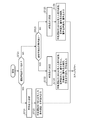
- FIG. 4 is a flowchart illustrating an operation of the driving support apparatus according to the first embodiment. It is a figure which shows the structural example of the vehicle which implement
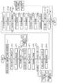
- FIG. 4 is a flowchart illustrating operations of a mode switching determination unit and an output control unit of the driving support device according to the first embodiment.
- 6 is a diagram illustrating an example of a screen display by an output control unit of the driving support apparatus according to Embodiment 1.
- FIG. 1 is a block diagram illustrating a configuration of a driving support device according to Embodiment 1.
- FIG. 2 is a diagram illustrating a hardware configuration example of a driving support device according to Embodiment 1.
- FIG. 4 is
- FIG. 4 is a flowchart illustrating operations of a mode switching determination unit and an output control unit of the driving support device according to the first embodiment. It is a figure which shows an example of the confirmation screen of the driving assistance request by the driving assistance device which concerns on Embodiment 1.
- FIG. It is a figure which shows an example of the confirmation screen displayed on a vehicle-mounted terminal according to the information which requests the driving assistance of the driving assistance device which concerns on Embodiment 1.
- FIG. It is a figure which shows an example of the screen for driving assistance displayed on a vehicle-mounted terminal based on the information from the driving assistance apparatus which concerns on Embodiment 1.
- FIG. 12A and 12B are diagrams illustrating an example of a screen for driving support displayed on the mobile terminal based on information from the driving support device according to Embodiment 1.
- FIG. 6 is a diagram illustrating a hardware configuration example of a server device of a driving support system according to Embodiment 2.
- FIG. 6 is a flowchart illustrating an operation of the driving support system according to the second embodiment.
- FIG. 1 is a block diagram illustrating a configuration of a driving support apparatus 100 according to the first embodiment.
- the driving support device 100 includes a vehicle information acquisition unit 1, an occupant information acquisition unit 2, a surrounding information acquisition unit 3, a mode switching determination unit 4, an output control unit 5, a driving control unit 6, a driving support control unit 7, a communication unit 8, and An input unit 9 is provided.
- the vehicle information acquisition unit 1 acquires vehicle state information, map information, road traffic information, and the like.
- the vehicle state information is information indicating the state of the host vehicle. For example, the current position information and traveling direction information of the vehicle received by a GPS (Global Positioning System) receiver mounted on the host vehicle, mounted on the host vehicle. These are vehicle speed information and acceleration information acquired by an engine ECU (Electronic Control Unit), steering angle information acquired by a sensor mounted on the host vehicle, and the like.
- GPS Global Positioning System
- the vehicle state information includes sensor information and the like necessary when the host vehicle performs automatic driving.
- Sensor information when performing automatic driving is, for example, distance information to an object located around the vehicle, acquired by a sensor using LIDAR (Light Detection and Ranging) technology mounted on the host vehicle, mounted on the host vehicle.
- LIDAR Light Detection and Ranging
- the distance information from the own vehicle to the preceding vehicle acquired by the millimeter wave radar, the travel distance information acquired by the tire rotation number detection unit, and the like.
- the map information and the road traffic information are acquired from a navigation system mounted on the host vehicle and an external database.
- the occupant information acquisition unit 2 refers to at least one of the captured image of the camera mounted on the host vehicle or the detection result of the sensor mounted on the host vehicle, and acquires the state information of the occupant of the vehicle.
- the vehicle occupant state information is information indicating whether the driver who is the vehicle occupant and the passenger are in a drivable state. Specifically, the occupant information acquisition unit 2 refers to the captured image and determines whether the driver is waking up, whether there is a passenger in the vehicle, whether the passenger is an adult, and so on. The state information of the vehicle occupant is acquired.
- the occupant information acquisition unit 2 refers to the detection result of the sensor, and the driver wakes up from the driver's body, whether the driver is seated in a normal posture or is lying down, or is lying down. It is determined whether the passenger is present or sleeping, the passenger is present, whether the passenger is an adult, or the passenger is an adult, and the vehicle occupant state information is acquired. Further, the occupant information acquisition unit 2 refers to information input by the occupant in advance, for example, whether a driver has a license, driving experience, age, etc., and determines whether there is a passenger who can drive other than the driver. To obtain state information of the vehicle occupant.
- the surrounding information acquisition unit 3 detects the presence and position of vehicles, pedestrians, obstacles, and the like existing around the host vehicle as state information around the vehicle based on the captured image of the camera mounted on the host vehicle and the detection result of the sensor. Get information.
- the mode switching determination unit 4 is obtained by the vehicle state information acquired by the vehicle information acquisition unit 1, the map information and road traffic information, the vehicle occupant state information acquired by the occupant information acquisition unit 2, and the peripheral information acquisition unit 3.
- the driving mode of the vehicle is switched based on the state information around the vehicle. Specifically, the mode switching determination unit 4 determines whether to switch the operation mode to a predetermined operation mode based on each state information and the like, and outputs the determination result to the output control unit 5, the operation control unit 6, and Output to the driving support control unit 7.
- the operation mode determined by the mode switching determination unit 4 includes, for example, an automatic operation mode in which the vehicle travels without depending on the driving operation of the occupant, an automatic operation end preparation mode in which preparation for terminating the automatic operation is performed, and requests external driving assistance.
- These include an external support preparation mode, an external support mode that travels based on external travel support, and a manual operation mode that travels according to the driving operation of the occupant.
- the driving support device 100 has these driving modes defined in advance.
- the output control unit 5 controls information output to the output device 200 based on the determination result of the mode switching determination unit 4.
- the output device 200 is, for example, a speaker, a display, a headlamp, a direction indicator, and an external speaker of the host vehicle.
- the output control unit 5 controls the output of the guidance sound or the warning sound from the speaker of the own vehicle, the control of outputting the guidance screen or the warning screen on the display of the own vehicle, etc. I do.
- the output control unit 5 controls to turn on the headlamp and the direction indicator of the host vehicle, and a sound for notifying the occurrence of an abnormality from the external speaker. Control to output guidance or warning sound.
- the operation control unit 6 When the continuation of the automatic operation mode is instructed from the mode switching determination unit 4 or a signal indicating the manual operation mode is input from the mode switching determination unit 4, the operation control unit 6 is directed to the vehicle control ECU (Electronic Control Unit) 300 of the host vehicle. Operation control for continuing automatic operation is performed, or operation control for switching from automatic operation to manual operation is performed.
- vehicle control ECU Electronic Control Unit
- the driving support control unit 7 requests the external device 400 for driving support via the communication unit 8 when the mode switching determination unit 4 is instructed to switch to the external support preparation mode. In addition, when the driving support control unit 7 obtains a response for permitting driving support from the external device 400 via the communication unit 8, the driving support control unit 7 outputs permission information to the mode switching determination unit 4 and also to the vehicle control ECU 300 of the host vehicle. In response to the driving assistance from the external device 400, the driving control is performed to continue the automatic driving.
- the external device 400 is a device such as an in-vehicle terminal, a portable terminal, or a server device, which will be described later, and is a device outside the vehicle that is not a device included in the host vehicle.
- the communication unit 8 performs communication between the driving support device 100 and the external device 400.
- the input unit 9 receives an input operation from the driver or passenger of the host vehicle via an input device (not shown), and outputs the received input information to the mode switching determination unit 4.
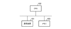
- FIG. 2 is a diagram illustrating a hardware configuration example of the driving support apparatus 100 according to the first embodiment.
- the communication unit 8 in the driving support device 100 is realized by the communication device 101 that performs communication with the external device 400.
- the vehicle information acquisition unit 1, occupant information acquisition unit 2, surrounding information acquisition unit 3, mode switching determination unit 4, output control unit 5, driving control unit 6, driving support control unit 7 and input unit 9 in the driving support device 100 are Realized by a processing circuit.
- the vehicle information acquisition unit 1, the occupant information acquisition unit 2, the peripheral information acquisition unit 3, the mode switching determination unit 4, the output control unit 5, the driving control unit 6, the driving support control unit 7, and the input unit 9 are the driver and A processing circuit is provided that switches driving modes according to the passenger's condition and performs driving control in response to driving support from the external device 400 when it is determined that driving support of the external device 400 is necessary.
- the processing circuit can be, for example, a single circuit, a composite circuit, a programmed processor, a processor programmed in parallel, an ASIC (Application Specific Integrated Circuit), an FPGA (Field-programmable Gate Array). ) Or a combination of these.
- the vehicle information acquisition unit 1, the occupant information acquisition unit 2, the peripheral information acquisition unit 3, the mode switching determination unit 4, the output control unit 5, the driving control unit 6, the driving support control unit 7 and the input unit 9 are processed. It may be realized by a circuit, or the functions of each unit may be realized by a processing circuit.
- the processing circuit is a CPU (Central Processing Unit)
- the processing circuit is a CPU 102 that executes a program stored in the memory 103 shown in FIG.
- the functions of the vehicle information acquisition unit 1, the occupant information acquisition unit 2, the peripheral information acquisition unit 3, the mode switching determination unit 4, the output control unit 5, the driving control unit 6, the driving support control unit 7 and the input unit 9 are software and firmware. Or a combination of software and firmware.
- Software or firmware is described as a program and stored in the memory 103.
- the CPU 102 reads out and executes a program stored in the memory 103, thereby executing a vehicle information acquisition unit 1, an occupant information acquisition unit 2, a surrounding information acquisition unit 3, a mode switching determination unit 4, an output control unit 5, and an operation control unit. 6.
- the functions of the driving support control unit 7 and the input unit 9 are realized. That is, the vehicle information acquisition unit 1, occupant information acquisition unit 2, peripheral information acquisition unit 3, mode switching determination unit 4, output control unit 5, driving control unit 6, driving support control unit 7 and input unit 9 are executed by the CPU 102. 3 is provided with a memory 103 for storing a program in which each step shown in FIG. 3 to be described later is executed as a result. These programs include a vehicle information acquisition unit 1, an occupant information acquisition unit 2, a peripheral information acquisition unit 3, a mode switching determination unit 4, an output control unit 5, a driving control unit 6, a driving support control unit 7, and an input unit 9. It can be said that the above procedure or method is executed by a computer.
- the CPU 102 is, for example, a central processing unit, a processing unit, an arithmetic unit, a processor, a microprocessor, a microcomputer, or a DSP (Digital Signal Processor).
- the memory 103 may be a nonvolatile or volatile semiconductor memory such as a RAM (Random Access Memory), a ROM (Read Only Memory), a flash memory, an EPROM (Erasable Programmable ROM), or an EEPROM (Electrically EPROM). Further, it may be a magnetic disk such as a hard disk or a flexible disk, or an optical disk such as a mini disk, CD (Compact Disc), or DVD (Digital Versatile Disc).
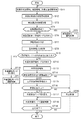
- FIG. 3 is a flowchart showing the operation of the driving support apparatus 100 according to the first embodiment.
- the vehicle information acquisition unit 1 acquires vehicle state information, map information, road traffic information, and the like, and outputs them to the mode switching determination unit 4 (step ST1).
- the occupant information acquisition unit 2 acquires the vehicle occupant state information and outputs it to the mode switching determination unit 4 (step ST2).
- the surrounding information acquisition unit 3 acquires state information around the vehicle and outputs it to the mode switching determination unit 4 (step ST3).
- the mode switching determination unit 4 refers to the vehicle state information acquired in step ST1, and determines whether or not the host vehicle can continue automatic driving (step ST4). In the determination of whether or not it is possible to continue the automatic driving in step ST4, the information to be referred differs depending on what information the host vehicle is using for the automatic driving. Details thereof will be described later.
- the mode switching determination unit 4 notifies the driving control unit 6 of the continuation of the automatic driving mode.
- the driving control unit 6 instructs the vehicle control ECU 300 to perform vehicle control in the automatic driving mode based on the notification from the mode switching determination unit 4 (step ST5), and returns to the processing of step ST1.
- the mode switching determination unit 4 switches the driving mode to the automatic driving end preparation mode, and outputs a signal corresponding to the switched mode. It outputs to the output control part 5 (step ST6). Further, the mode switching determination unit 4 refers to the vehicle occupant state information acquired by the vehicle occupant information acquisition unit 2, determines whether the driver and the passenger are in a state where the vehicle can be driven, and determines the determination result. It outputs to the output control part 5 (step ST7).
- the output control unit 5 refers to the determination result output in step ST7 based on the signal indicating the automatic driving end preparation mode notified in step ST6, and outputs voice guidance, warning sound, guidance screen, Control for outputting a warning screen or the like is performed (step ST8).
- the mode switching determination unit 4 is controlled to perform manual operation via the input unit 9 after a predetermined time has elapsed since the output of voice guidance, warning sound, guidance screen, warning screen, etc. is performed under the control of step ST8. It is determined whether or not a switching response has been input (step ST9).
- the response to switching to manual operation is an operation input by the driver for permitting switching to manual operation on a display screen that prompts the driver to input a response to switching to manual operation described later. It is.
- the mode switching determination unit 4 switches the operation mode to the manual operation mode and notifies the operation control unit 6 (step ST10).
- the driving control unit 6 instructs the vehicle control ECU 300 to perform driving control in the manual driving mode notified in step ST10 (step ST11), and ends the process.
- the mode switching determination unit 4 switches the driving mode to the external support preparation mode and notifies the output control unit 5 and the driving support control unit 7 (step). ST12). Based on the external support preparation mode notified in step ST12, the output control unit 5 performs control to notify the output device 200 of the occurrence of an abnormality outside the host vehicle (step ST13).
- the driving support control unit 7 searches for an external device 400 that can be communicably connected via the communication unit 8, and determines whether or not the external device 400 exists (step ST14). If there is a communicable external device 400 (step ST14; YES), information requesting the external device 400 for travel support is output (step ST15). The driving support control unit 7 determines whether or not a response to permit driving support is input from the external device 400 via the communication unit 8 to the information requesting driving support output in step ST15 (step ST16). ). When a response for permitting driving support is input (step ST16; YES), the driving support control unit 7 notifies the mode switching determination unit 4 that a response for permitting driving support has been input.
- the mode switching determination unit 4 switches the driving mode to the external support mode based on the notification from the driving support control unit 7, and notifies the driving support control unit 7 again (step ST17).
- the driving support control unit 7 instructs the vehicle control ECU 300 to perform driving control in the external support mode notified in step ST17 (step ST18).
- the driving support control unit 7 refers to the control state of the vehicle control ECU 300 to determine whether or not the traveling of the host vehicle has ended (step ST19). When the driving support control unit 7 determines that the traveling of the host vehicle has ended (step ST19; YES), the process ends. On the other hand, when the driving assistance control part 7 determines with the driving
- step ST14 when there is no communicable external device 400 (step ST14; NO), and when a response for permitting driving support is not input from the external device 400 (step ST16; NO), the driving support control unit 7 selects the own vehicle.
- the operation control to be stopped is instructed to the vehicle control ECU 300 (step ST20), and the process ends.
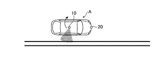
- FIG. 4 is a diagram illustrating a configuration example of a vehicle that includes the driving support device 100 according to the first embodiment and realizes automatic driving by driving control by the driving support device 100.
- the host vehicle A has the sensor 10 using the LIDAR technology mounted on the roof portion, and recognizes the structure of the three-dimensional space around the host vehicle A while the sensor 10 rotates 360 degrees.
- the host vehicle A has a millimeter wave radar 20 mounted in front of the vehicle, and the millimeter wave radar 20 detects the distance between the host vehicle and the preceding vehicle.
- the host vehicle A receives a position information of the host vehicle A by a GPS receiver (not shown), a driving lane information for supporting automatic driving by a receiver (not shown), and a camera (not shown) displays a road lane image.
- the information necessary for realizing the automatic driving is acquired, for example, the tire rotation speed detection unit (not shown) acquires the travel distance information.
- the mode switching determination unit 4 determines that the host vehicle cannot continue automatic driving in the process of step ST4. (Step ST4; NO). Further, when the vehicle information acquisition unit 1 receives information, for example, that the driving lane information for automatic driving ends 5 km ahead, the mode switching determination unit 4 continues the automatic driving of the host vehicle A in the process of step ST4. It is determined that it cannot be performed (step ST4; NO).
- the vehicle information acquisition unit 1 correctly acquires the structure of the three-dimensional space, the distance from the preceding vehicle, the position information of the host vehicle, the travel lane information, the road lane image, and the travel distance information necessary for automatic driving. If it is possible, the mode switching determination unit 4 determines in step ST4 that the host vehicle can continue automatic driving (step ST4; YES). As step ST5, the driving control unit 6 uses the structure of the three-dimensional space acquired by the vehicle information acquisition unit 1, the distance to the preceding vehicle, the position information of the host vehicle, the travel lane information, the road lane image, and the travel distance information. Thus, the vehicle control ECU 300 is instructed to perform driving control in automatic driving.
- FIG. 5 is a flowchart showing the operations of the mode switching determination unit 4 and the output control unit 5 of the driving assistance apparatus 100 according to the first embodiment.
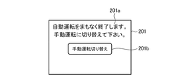
- FIG. 6 is a diagram illustrating an example of a screen display by the output control unit 5 of the driving assistance apparatus 100 according to the first embodiment.
- the mode switching determination unit 4 refers to the vehicle occupant state information output in step ST2 to determine whether or not the driver is awake (step ST21). When the driver is waking up (step ST21; YES), the mode switching determination unit 4 notifies the output control unit 5 that the driver is waking up, and the output control unit 5 notifies the driver based on the notification. On the other hand, a display screen and voice guidance for requesting input of a response to switching to manual operation are output to output device 200 (step ST22).
- step ST21 when the driver is not awake (step ST21; NO), the mode switching determination unit 4 determines whether there is a passenger who can drive further (step ST23). When there is a driveable passenger (step ST23; YES), the mode switching determination unit 4 notifies the output control unit 5 that the driver is not awake and that there is a driveable passenger, and outputs it. Based on the notification, the control unit 5 outputs a display screen and voice guidance for requesting the driver to input a response to switching to manual driving, and a warning sound for notifying the driver of warning. A display screen, voice guidance, and the like that warn of the termination are output to output device 200 (step ST24). In addition, in the determination process of step ST23, in addition to the determination whether a fellow passenger exists, the determination whether a fellow passenger is occurring may be performed together.
- the mode switching determination unit 4 notifies the output control unit 5 that the driver is not awake, and the output control unit 5 is based on the notification.
- the output device 200 provides a display screen and voice guidance for requesting the driver to input a response to switching to manual driving, and a display screen, voice guidance, warning sound and the like for warning the driver that the automatic driving will be terminated soon.
- the output control unit 5 may be configured to control the in-vehicle device so as to vibrate the driver's seat, blow air or cold air to the driver, and blow scented or scented air.
- step ST24 and step ST25 the structure which performs the display screen and audio
- step ST22 When the output control unit 5 performs output control in any of step ST22, step ST24, or step ST25, information corresponding to the output device 200 is output. Thereafter, the process proceeds to step ST9 in the flowchart of FIG.
- FIG. 6 shows an example of a display screen for requesting input of a switching response to manual operation output in step ST22, step ST24 and step ST25 in the flowchart of FIG.
- the display screen 201 displays information 201a indicating that the automatic operation will soon be terminated and it is necessary to switch to manual operation, and an operation button 201b for responding to switching to manual operation.
- the operation button 201 b corresponds to the input unit 9 of the driving support device 100.
- the mode switching determination unit 4 determines that a switching response to manual driving has been input (step ST9; YES), and switches to manual driving mode as step ST10.
- step ST11 the driving control unit 6 instructs the vehicle control ECU 300 to perform driving control in manual driving.
- the mode switching determination unit 4 determines that a switching response to manual operation is not input (step ST9; NO), and switches to the external support preparation mode as step ST12. .
- the mode switching determination unit 4 In addition to determining whether the driver and the passenger are capable of driving the vehicle, the mode switching determination unit 4 is dangerous to travel the vehicle according to the state of the driver and the passenger. It is also possible to calculate the urgency level of a warning indicating whether or not it is necessary.
- the output control unit 5 considers the urgency level of the warning, and outputs the warning information for performing output control in step ST8 and the notification information for performing output control in step ST12. The output mode and the like may be changed.
- FIG. 7 shows processing operations of the mode switching determination unit 4 and the output control unit 5 when the urgent level of warning is also taken into consideration.
- FIG. 7 is a flowchart showing the operations of the mode switching determination unit 4 and the output control unit 5 of the driving assistance apparatus 100 according to Embodiment 1, and is a flowchart showing the operation of the output control in consideration of the urgent level of warning.
- the mode switching determination unit 4 determines that the driver is waking up (step ST21; YES)
- the mode urgency level is set to “1” (step ST31).
- the output control unit 5 refers to the warning urgency level “1” set in step ST31, and outputs a display screen and voice guidance for requesting the driver to input a response to switching to manual driving to the output device 200. (Step ST22).
- the mode switching determination unit 4 sets the emergency level of warning to “2” (step ST21).
- the output control unit 5 refers to the warning urgency level “2” set in step ST32, displays a screen for prompting the driver to input a response to switching to manual driving, voice guidance, and warning for notifying the driver of warning. A sound is output, and further, a display screen and voice guidance for warning the passenger that automatic driving will be finished soon are output to the output device 200 (step ST24). Since the warning urgency is “2”, the output control unit 5 outputs a warning sound for the driver, a warning display screen for the passenger, and a voice guidance for the warning in the output control in step ST24.
- the mode switching determination unit 4 sets the emergency level of warning to “3” (step ST21).
- the output control unit 5 refers to the warning urgency level “3” set in step ST32, displays a screen for prompting the driver to input a response to switching to manual driving, voice guidance, and further automatically driving the driver.
- a display screen, a voice guidance, a warning sound, and the like that warn that it will soon be terminated are output to the output device 200 (step ST25).
- the output control unit 5 increases the volume of the warning sound, displays a warning screen, vibrates the driver seat, and sends air to the driver in the output control of step ST25.
- an output such as applying cold air or blowing air with a scent or smell.
- the mode switching determination unit 4 can set the warning urgency level, and the output control unit 5 can perform output control according to the set warning urgency level.
- the output control part 5 showed the structure which determines the output content in a vehicle, an output mode, and an output destination according to the emergency degree of warning above, the output content outside a vehicle and output according to the emergency degree of warning It is also possible to determine the mode and output destination.
- driving support device 100 performs driving control by receiving driving support from the external device 400 in the external support preparation mode and the external support mode.
- the external device 400 is an in-vehicle terminal such as a navigation system mounted on a vehicle around the host vehicle.
- driving support is realized by communication connection between the driving support device 100 and in-vehicle terminals of surrounding vehicles, and the own vehicle A provides driving support by inter-vehicle communication with the surrounding vehicle X. It is what you receive.
- a description will be given along the flowchart shown in FIG. 3, particularly based on the processing shown in steps ST14 to ST20.
- the driving support control unit 7 uses a wireless LAN (Local Area Network) based on the Wi-Fi standard or the like via the communication unit 8 in step ST14. It is determined whether there is a surrounding vehicle equipped with an in-vehicle terminal that can be connected by the communication. In step ST14, when there is an in-vehicle terminal that can be connected to the periphery of the host vehicle A, the driving support control unit 7 establishes a communication connection with the in-vehicle terminal.
- LAN Local Area Network
- the driving support control unit 7 selects, for example, the in-vehicle terminal of the vehicle closest to the own vehicle A or the in-vehicle terminal that responds the fastest. For example, communication connection may be established.
- the communication unit 8 When there is a surrounding vehicle X equipped with an in-vehicle terminal capable of communication connection (step ST14; YES), the communication unit 8 establishes communication connection with the in-vehicle terminal of the surrounding vehicle X, and in step ST15, the driving support control unit 7 Outputs information requesting driving support to the in-vehicle terminal.
- the driving support control unit 7 may output the current position information of the own vehicle A, the vehicle information such as the vehicle type of the own vehicle A, and the surrounding map information together with the information requesting the driving support.
- FIG. 8 is a diagram illustrating an example of a confirmation screen for a travel support request by the output control unit 5 of the driving support device 100 according to the first embodiment.
- the display screen 202 includes information 202a indicating that automatic driving cannot be continued and it is necessary to request driving support, an operation button 202b for selecting to request driving support, and an operation for selecting not to request driving support.
- the button 202c is not input, information 202d indicating that the driving support is automatically requested is displayed.
- the operation buttons 202b and 202c correspond to the input unit 9 of the driving support device 100.
- step ST16 When the operation button 202b is pressed, or when none of the operation buttons 202b and 202c are input within a predetermined time after the display screen 202 is displayed, the process proceeds to step ST16 and the driving support control unit 7 Is configured to output information requesting driving support to the in-vehicle terminal of the surrounding vehicle X.
- the mode switching determination unit 4 may determine that the driver has returned to a state where manual driving can be performed, and may proceed to step ST10, or return to the determination process of step ST9. You may comprise.
- FIG. 9 is a diagram illustrating an example of a confirmation screen displayed on the in-vehicle terminal that is the external device 400 according to the information for requesting the driving assistance of the driving assistance device 100 according to the first embodiment.
- an icon 401a of the surrounding vehicle X On the confirmation screen 401, an icon 401a of the surrounding vehicle X, an icon 401b of the own vehicle A that is requesting driving assistance, and an area indicating the relative position of the own vehicle A drawn based on the current position information of the own vehicle A 401c, surrounding map information 401d, information 401e notifying that the own vehicle A seeks driving support, an operation button 401f for selecting driving support, and an operation button 401g for selecting not driving support are displayed. .
- the result of the driver of the surrounding vehicle X pressing one of the operation buttons 401 f and 401 g is input as a response to the driving support control unit 7 via the communication unit 8.
- the driving support control unit 7 proceeds to the process of NO in step ST16 based on the input response that does not permit the driving support.
- the driving support control unit 7 performs driving control for stopping the host vehicle A on the vehicle control ECU 300, and ends the process. For example, the driving support control unit 7 performs driving control for stopping the vehicle A by automatically driving the vehicle A to the evacuation area or the parking area.
- the driving support control unit 7 performs the process of YES in step ST16 based on the input response for permitting driving support. Proceed to When a response for permitting driving support is input from the driving support control unit 7, the mode switching determination unit 4 switches the driving mode of the host vehicle A to the external support mode as step ST17. As step ST18, the driving support control unit 7 sends the current position information of the own vehicle A, the destination information of the own vehicle A, and the position information suitable for the own vehicle A to follow the surrounding vehicle X via the communication unit 8. Output to the in-vehicle terminal of the surrounding vehicle X. Here, the driving support control unit 7 acquires position information suitable for the host vehicle A to follow the surrounding vehicle from the surrounding information acquired by the surrounding information acquisition unit 3.
- FIG. 10 is a diagram illustrating an example of a screen for driving assistance displayed on the in-vehicle terminal that is the external device 400 based on information from the driving assistance apparatus 100 according to the first embodiment.
- the screen information on the screen 402 shown in FIG. 10 may be created by the in-vehicle terminal of the surrounding vehicle X, or created by the driving support device 100 of the own vehicle A and transmitted to the in-vehicle terminal of the surrounding vehicle X. Also good.
- an icon 402a of the surrounding vehicle X On the driving support screen 402, an icon 402a of the surrounding vehicle X, an icon 402b of the own vehicle A seeking driving support, the surrounding map information 402c, and an arrow 402d indicating the direction and position where the surrounding vehicle X should move. And the area 402e, information 402f that prompts the driver of the surrounding vehicle X to move to the area 402e is displayed.
- the driver of the surrounding vehicle X travels by moving the surrounding vehicle X to the area 402e in front of the host vehicle A based on the screen 402 for traveling support shown in FIG.
- the driving support control unit 7 of the driving support device 100 refers to the surrounding information acquired by the surrounding information acquisition unit 3 and recognizes the surrounding vehicle X that performs the driving support to the vehicle control ECU 300 to the surrounding vehicle X. Control information for instructing to follow the vehicle is output.
- the driving support control unit 7 is required to follow the surrounding vehicle X with the camera and sensor mounted on the host vehicle A by applying, for example, an automatic driving technique.
- Information is acquired and the driving
- the destination is arbitrarily set in the traveling in which the own vehicle A follows the surrounding vehicle X.
- a parking area in which the driver of the surrounding vehicle X determines that the host vehicle A can be stopped may be set as the destination.
- the in-vehicle terminal of the surrounding vehicle X refers to the destination information of the own vehicle A and the surrounding vehicle X, and if the respective destinations are greatly different, the nearest parking area is selected and set as the destination. Alternatively, when the respective destinations are close, a parking area around the destination may be selected and set as the destination.
- the driving support is realized by communication connection between the driving support device 100 and the portable terminal Y carried by the pedestrian.
- a description will be given along the flowchart shown in FIG. 3, particularly based on the processing shown in steps ST14 to ST20.
- the driving support control unit 7 determines whether there is a mobile terminal that can be connected via the communication unit 8 as step ST14.
- step ST14 when there is a mobile terminal Y capable of communication connection in the vicinity of the host vehicle A, the driving support control unit 7 establishes a communication connection with the mobile terminal Y.
- the driving support control unit 7 may establish a communication connection by selecting the mobile terminal that responded earliest, for example. .
- the communication unit 8 When there is a mobile terminal Y that can be connected (step ST14; YES), the communication unit 8 establishes communication connection with the mobile terminal Y, and in step ST15, the driving support control unit 7 requests the mobile terminal Y for driving support. Output information. Further, the driving support control unit 7 may output the current position information of the own vehicle A, the vehicle information such as the vehicle type of the own vehicle A, and the surrounding map information together with the information requesting the driving support.
- step ST15 before outputting the information for requesting the driving support in step ST15, whether the output control unit 5 requests the external device 400 for driving support from a speaker or a display in the vehicle that is the output device 200 of the host vehicle A. You may comprise so that the audio guidance or screen display etc. to confirm may be output (refer FIG. 8).
- the operation button 202b in FIG. 8 is pressed, or when none of the operation buttons 202b and 202c are input within a predetermined time after the display screen 202 is displayed, the process proceeds to step ST15 and driving assistance is performed.
- the control unit 7 is configured to output information requesting driving support to the portable terminal Y.
- the mode switching determination unit 4 may determine that the driver has returned to a state where manual driving can be performed, and may proceed to the process of step ST10, or the determination process of step ST9 You may comprise so that it may return to.
- FIG. 11 is a diagram illustrating an example of a confirmation screen displayed on the mobile terminal that is the external device 400 in accordance with information for requesting driving assistance of the driving assistance device 100 according to the first embodiment.
- the confirmation screen 403 includes an icon 403a of the host vehicle A, surrounding map information 403b, information 403c for notifying that the host vehicle A is seeking driving support, an operation button 403d for selecting driving support, and no driving support. An operation button 403e for selecting this is displayed.
- the result of the pedestrian carrying the portable terminal Y pressing one of the operation buttons 403d and 403e is input as a response to the driving support control unit 7 via the communication unit 8.
- the driving support control unit 7 performs the process of NO in step ST16 based on the input response that does not permit driving support. Proceed to As step ST20, the driving support control unit 7 performs driving control for stopping the host vehicle A on the vehicle control ECU 300, and ends the process. For example, the driving support control unit 7 performs driving control for stopping the vehicle A by automatically driving the vehicle A to the evacuation area or the parking area.
- the driving support control unit 7 proceeds to a process of YES in step ST16 based on the input response for permitting driving support.
- the mode switching determination unit 4 receives from the driving support control unit 7 that the driving support is enabled, the mode switching determination unit 4 switches the driving mode of the host vehicle A to the external support mode as step ST17.
- the driving support control unit 7 outputs the current position information of the host vehicle A and map information around the host vehicle A to the portable terminal Y via the communication unit 8.
- FIGS. 12A and 12B are diagrams illustrating an example of a screen for driving support displayed on the mobile terminal that is the external device 400 based on information from the driving support apparatus 100 according to Embodiment 1.
- FIG. Note that the screen information shown in FIGS. 12A and 12B may be created by the portable terminal Y, or may be created by the driving support device 100 of the host vehicle A and transmitted to the portable terminal Y.
- an icon 404a of the host vehicle A seeking driving support an icon 404a of the host vehicle A seeking driving support, information 404b instructing movement of the icon 404a, and surrounding map information 404c are displayed.
- the information 404b is displayed, for example, “Please move the icon to a position where it can be stopped”, and asks you to specify where to stop the vehicle A.
- the pedestrian carrying the portable terminal Y drags and drops the icon 404a into the area 404d such as private land where the host vehicle A can be parked, and moves it to the position of the icon 404e. Thereby, the stop area
- information 404f for requesting rotation of the icon 404e shown in FIG. 12B is displayed on the screen 404 of the portable terminal Y.
- the information 404f is displayed, for example, “Please rotate the icon to match the direction when the vehicle is stopped” and request to specify the direction in which the host vehicle A is to be stopped.
- a pedestrian carrying the portable terminal Y rotates the icon 404e according to the assumed stop direction of the host vehicle A based on the information 404f. Thereby, the stop direction of the own vehicle A is determined.
- information 404g for requesting drawing of the moving route of the host vehicle A shown in FIG. 12B is displayed.
- the information 404g is displayed, for example, “Please draw a route from the icon to the stop area”, and requests that the host vehicle A designate a route to be moved.
- a pedestrian carrying the portable terminal Y draws a movement path 404i from the icon 404h indicating the current position of the host vehicle A to the icon 404e on the screen 404 based on the information 404g.
- the mobile terminal Y transmits the position information and direction information of the icon 404e, the position information of the icon 404h, and information indicating the movement path 404i from the icon 404h to the icon 404e to the driving support device 100.
- the driving support control unit 7 of the driving support device 100 receives the position information and direction information of the icon 404e, the position information of the icon 404h, and information indicating the movement path 404i from the icon 404h to the icon 404e via the communication unit 8. .
- the driving support control unit 7 instructs the vehicle control ECU 300 to perform driving control that causes the host vehicle A to travel at a low speed according to the movement route 404i and stop at the position of the icon 404e.
- the driving support control unit 7 refers to the control state of the vehicle control ECU 300, and when the host vehicle A stops at the position of the icon 404e, the driving support control unit 7 determines that the traveling of the host vehicle A has ended (step ST19; YES). The process is terminated.
- step ST18 when the driving support control unit 7 determines from the surrounding information of the host vehicle A acquired by the surrounding information acquisition unit 3 that it cannot travel on the set route, the communication unit 8 is turned on. Information for requesting the mobile terminal Y to reset the travel route.
- the case where the host vehicle A cannot travel on the route is, for example, the case where the vehicle cannot travel on the set route based on the road width and the vehicle width of the host vehicle A, or other than the planned stop position. This is the case when the vehicle is stopped.
- the mobile terminal Y that has received the information for requesting the resetting of the moving route displays the screen shown in FIG. 12A together with a message for requesting the resetting, and again seeks the setting of the stop position of the host vehicle A and the moving route.
- the driving support control unit 7 outputs information instructing the vehicle control ECU 300 to travel at a low speed while requesting the mobile terminal Y to reset the movement route. In addition, the driving support control unit 7 instructs the vehicle control ECU 300 to stop if the moving route that the host vehicle A can travel is not found even if the request for resetting the moving route is performed N times. You may comprise so that the information to perform may be output.
- the determination as to whether or not there is an externally connectable external device 400 in step ST14 in the flowchart of FIG. 3 may be performed simultaneously on both the in-vehicle terminal mounted on the surrounding vehicle and the portable terminal carried by the pedestrian.
- the driving support control unit 7 outputs information for requesting driving support in step ST15 in the flowchart of FIG. 3 simultaneously to both the in-vehicle terminal mounted on the surrounding vehicle and the portable terminal carried by the pedestrian. May be.
- the vehicle state information acquired by the vehicle information acquisition unit 1, the vehicle occupant state information acquired by the occupant information acquisition unit 2, and the surrounding information acquisition unit 3 are acquired. From the automatic driving mode in which the mode switching determination unit 4 that switches the driving mode of the vehicle and the driving mode that the mode switching determination unit 4 switches based on the vehicle surrounding state information travels without depending on the driving operation of the occupant, When the mode switching determination unit 4 determines that the occupant cannot drive from the state information of the occupant of the vehicle when the mode switching determination unit 4 prepares to shift to the manual operation mode that travels according to the occupant's driving operation.
- a driving support control unit 7 that requests driving assistance from a device outside the vehicle and controls driving of the vehicle based on a response input from the device outside the vehicle in response to the request for driving assistance; Since it is configured to, it can be based on the traveling support by outside equipment to dynamically set the region to stop the vehicle, to continue the automatic operation to the set region. Thereby, even when it is a case where automatic driving
- the output control unit 5 when the mode switching determination unit 4 determines that the occupant cannot drive, the output control unit 5 performs control to output warning information to at least one of the inside of the vehicle and the outside of the vehicle. Therefore, it is possible to perform control so that an occupant can return to driving and to notify the occurrence of abnormality of the vehicle outside the vehicle.
- the mode switching determination unit 4 sets the emergency level of warning based on the state information of the vehicle occupant, and the output control unit 5 responds to the set warning level of emergency. Since at least one of the output content, output mode, and output destination of the warning information is determined, output control according to the urgency level of the warning can be performed.
- the configuration in which the communication unit 8 establishes a connection with the in-vehicle terminal or the portable terminal by communication using the wireless LAN by Wi-Fi is shown.
- the communication by the wireless LAN by Wi-Fi is shown.
- communication using Bluetooth (registered trademark) or the like is also applicable.
- FIG. 13 is a diagram illustrating a configuration of the driving support system according to the second embodiment.
- the driving support system includes a driving support device 100, a server device 500, and an external device 400.
- the driving support device 100 is connected to the server device 500 and the external device 400 by wireless communication or the like.
- the driving support apparatus 100 can be connected to the in-vehicle terminal 410 and the portable terminal 420 of the external device 400 by communication using Wi-Fi or Bluetooth.
- Server device 500 is connected to each device of external device 400 by wireless communication or the like.
- the driving support device 100 has the same configuration as that of the driving support device 100 shown in FIG.
- the driving support control unit 7 transmits information requesting driving support to the server device 500 via the communication unit 8.
- the information for requesting driving support includes the current position information of the host vehicle, vehicle information such as the model of the host vehicle, and surrounding map information.
- the driving support control unit 7 receives the search result of the external device 400 corresponding to the information requesting the driving support from the server device 500, the driving support control unit 7 sends the external device 400 indicated in the search result to the external device 400 via the communication unit 8. Request driving assistance.
- the driving support control unit 7 continues driving automatically by receiving driving support from the outside to the vehicle control ECU 300 of the host vehicle. To control the operation.
- the server device 500 includes a communication unit 501, a search unit 502, a device database 503, and a device determination unit 504.
- the communication unit 501 establishes a communication connection between the server device 500 and the driving support device 100 and a communication connection between the server device 500 and the external device 400.
- the search unit 502 searches for an external device 400 that can currently perform driving support with reference to the device database 503 based on the information requesting driving support received via the communication unit 501.
- the search unit 502 inquires of the searched external device 400 through the communication unit 501 whether or not it is currently possible to perform driving support.
- the device database 503 is an area in which an external device 400 that has been previously permitted to perform driving support is registered. Further, the device database 503 may be configured to register current position information periodically transmitted from the external device 400 together.
- the device determining unit 504 determines an external device 400 that requests driving support based on the response content.
- the device determination unit 504 transmits information of the external device 400 that has been determined to request driving support to the driving support device 100 via the communication unit 501.
- the device determination unit 504 transmits information for requesting travel support to the external device 400 that has been determined to request travel support via the communication unit 501.
- the external device 400 can park a vehicle-mounted terminal 410 such as a navigation system mounted on a vehicle other than the host vehicle, a mobile terminal 420 such as a smartphone carried by a pedestrian, and a vehicle provided in a site such as a commercial facility.
- the facility management terminal 430 manages the parking state of the parking area.
- the in-vehicle terminal 410, the portable terminal 420, and the facility management terminal 430 are registered in advance.
- the in-vehicle terminal 410 and the portable terminal 420 are devices that can perform driving support
- the facility management terminal 430 is a facility terminal that can provide a parking area to a vehicle that requires driving support. Registered.
- FIG. 14 is a diagram illustrating a hardware configuration example of the server device 500 of the driving support system according to the second embodiment.
- the communication unit 501 in the server device 500 is realized by a communication device 511 that performs communication between the driving support device 100 and the external device 400.
- the search unit 502 and the device determination unit 504 in the server device 500 search for a device that can perform travel support using the input information for requesting travel support, and determine a device that requests travel support. Provide circuit.
- the processing circuit can be, for example, a single circuit, a composite circuit, a programmed processor, a processor programmed in parallel, an ASIC (Application Specific Integrated Circuit), an FPGA (Field-programmable Gate Array). ) Or a combination of these.
- the functions of the respective units of the search unit 502 and the device determination unit 504 may be realized by a processing circuit, or the functions of the respective units may be collectively realized by a processing circuit.
- the processing circuit When the processing circuit is a CPU, the processing circuit is a CPU 512 that executes a program stored in the memory 513 shown in FIG.
- the functions of the search unit 502 and the device determination unit 504 are realized by software, firmware, or a combination of software and firmware.
- Software or firmware is described as a program and stored in the memory 513.
- the CPU 512 implements the functions of the search unit 502 and the device determination unit 504 by reading and executing the program stored in the memory 513. That is, the search unit 502 and the device determination unit 504 include a memory 513 for storing a program that, when executed by the CPU 512, results in each step shown in FIG. These programs can also be said to cause the computer to execute the procedures or methods of the search unit 502 and the device determination unit 504.
- the CPU 512 is, for example, a central processing unit, a processing unit, an arithmetic unit, a processor, a microprocessor, a microcomputer, or a DSP.
- the memory 513 may be a nonvolatile or volatile semiconductor memory such as RAM, ROM, flash memory, EPROM, or EEPROM, or may be a magnetic disk such as a hard disk or a flexible disk, or a mini disk. An optical disc such as a CD or a DVD may be used.
- FIG. 15 is a flowchart illustrating the operation of the driving support system according to the second embodiment.
- the driving support control unit 7 is connected to the server device via the communication unit 8.
- Information for requesting driving assistance is transmitted to 500 (step ST41).
- the search unit 502 refers to the device database 503 using the information for requesting the travel support, and provides the travel support.
- the external device 400 that can be used is searched (step ST42). Specifically, the search unit 502 searches the in-vehicle terminal 410 and the portable terminal 420 located around the host vehicle from the current position information of the host vehicle included in the information requesting the driving support, The facility management terminal 430 of the facility having a parking area is searched for.
- the search unit 502 determines whether or not there is an external device 400 that can perform driving support (step ST43).
- the communication unit 501 transmits a request for driving support to the external device 400 searched in step ST42 (step ST44).
- step ST44 In response to the travel support request transmitted in step ST44, external device 400 inputs a response for permitting travel support and transmits the response to server device 500 (step ST45).
- step ST45 description will be made assuming that the in-vehicle terminal 410, the portable terminal 420, and the facility management terminal 430 transmit a response for permitting driving support to the server device 500.
- the communication unit 501 of the server device 500 receives the response for permitting the travel support transmitted in step ST45 (step ST46), and outputs the response to the device determination unit 504.
- the device determination unit 504 refers to the permission information received in step ST46, and determines the external device 400 that requests driving support (step ST47).
- the device determination unit 504 instructs the external device 400 that has been determined to request travel support in step ST47 and the driving support device 100 via the communication unit 501 to establish a communication connection, and operates with the external device 400 that has received the instruction.
- the support device 100 performs communication connection (step ST48).
- the driving support control unit 7 When the communication connection between the external device 400 and the driving support device 100 is established, the driving support control unit 7 notifies the mode switching determination unit 4 that a response for permitting driving support has been input.
- the mode switching determination unit 4 switches the driving mode to the external support mode based on the notification from the driving support control unit 7, and outputs a signal indicating the external support mode to the driving support control unit 7 again (step ST49). Thereafter, the flowchart proceeds to step ST18.
- step ST43 when there is no external device 400 capable of performing driving support (step ST43; NO), the search unit 502 notifies the driving support device 100 that driving support cannot be requested via the communication unit 501. (Step ST50).
- the driving support control unit 7 of the driving support device 100 instructs the vehicle control ECU 300 to perform driving control for stopping the host vehicle (step ST20), and ends the process.
- the device determination unit 504 may determine the external device 400 that requests travel support based on a preset priority. For example, it is assumed that the device determination unit 504 has a priority of requesting driving support in the order of the in-vehicle terminal 410, the portable terminal 420, and the facility management terminal 430. When the device determination unit 504 receives a response permitting driving support from the in-vehicle terminal 410, the portable terminal 420, and the facility management terminal 430, it requests the in-vehicle terminal 410 for driving support in consideration of the priority. In addition, the device determination unit 504 may have a priority of requesting driving support in the order of a short distance from the host vehicle.
- the device determination unit 504 determines the priority when the parking area managed by the facility management terminal 430 is located closest to the host vehicle among the external devices 400 that have transmitted the response for permitting driving support. Considering this, the facility management terminal 430 is requested to provide driving assistance.
- step ST47 when the in-vehicle terminal 410 is determined as the external device 400 that requests the travel support, the process in which the in-vehicle terminal 410 performs the travel support is the same as in the first embodiment. Description is omitted. Further, when the mobile terminal 420 is determined as the external device 400 that requests the travel support in the process of step ST47 described above, the process in which the mobile terminal 420 performs the travel support is the same as in the first embodiment. Therefore, the description is omitted.
- step ST47 when the facility management terminal 430 is determined as the external device 400 that requests the travel support, the facility management terminal 430 performs the travel support.
- the facility management terminal 430 detects the location information of the facility, the location information of the entrance to the facility, and the own vehicle is parked in the facility. Information indicating an area that can be used is transmitted to the driving support apparatus 100 as information on a parking area.
- the driving support control unit 7 determines the travel route to the facility, the approach route to the facility, and the travel route to the parking area based on the transmitted information on the parking available region. And the driving control for driving the host vehicle to the parking area is output to the vehicle control ECU 300.
- the facility management terminal 430 is connected to the driving support device 100 by wireless communication or the like. However, even if the facility management terminal 430 cannot be connected to the driving support device 100 by communication, driving support is provided. Can be done.
- the facility management terminal 430 may be connected to the server device 500 by communication.
- the facility management terminal 430 transmits information on the above-described parking area to the server device 500.
- the server device 500 transfers the received parking area information to the driving support device 100.
- the driving support control unit 7 determines the travel route to the facility, the approach route to the facility, and the travel route to the parking area based on the transferred information on the parking available region. Etc., and the driving control for driving the host vehicle to the parking area is output to the vehicle control ECU 300.
- FIG. 13 you may comprise so that portable terminals, such as a smart phone, may be equipped with the function of each structure shown as the driving assistance apparatus 100.
- FIG. 13 you may comprise so that portable terminals, such as a smart phone, may be equipped with the function of each structure shown as the driving assistance apparatus 100.
- the configuration is such that the external device 400 that can request the travel support via the server device 500 is searched, so the search for the external device that requests the travel support is performed.
- Efficiency can be improved and the object which requests driving assistance can be expanded.
- the present invention can be freely combined with each embodiment, modified any component of each embodiment, or omitted any component in each embodiment. Is possible.
- the driving support device can switch the driving mode based on the state information of the vehicle occupant and can request driving assistance from an external device, so it is applied to a vehicle equipped with an automatic driving function, Control performance at the time of transition from automatic operation to manual operation can be improved.
Landscapes
- Engineering & Computer Science (AREA)
- Radar, Positioning & Navigation (AREA)
- Remote Sensing (AREA)
- Physics & Mathematics (AREA)
- General Physics & Mathematics (AREA)
- Automation & Control Theory (AREA)
- Traffic Control Systems (AREA)
Abstract
L'invention concerne un dispositif d'aide à la conduite qui comprend une unité de détermination de commutation de mode (4) servant à commuter un mode de conduite de véhicule sur la base d'informations d'état de véhicule, d'informations d'état d'occupant de véhicule et d'informations d'état de voisinage de véhicule, et une unité de commande d'aide à la conduite (7) qui émet des informations demandant qu'un dispositif à l'extérieur du véhicule facilite le déplacement du véhicule si le mode auquel a commuté l'unité de détermination de commutation de mode (4) est un mode de préparation de fin de conduite automatique pour préparer la transition d'un mode de conduite automatique, dans lequel le véhicule se déplace sans manœuvre de conduite d'occupant, à un mode de conduite manuelle, dans lequel le véhicule se déplace selon une manœuvre de conduite d'occupant, et l'unité de détermination de commutation de mode a déterminé à partir des informations d'état d'occupant de véhicule que l'occupant ne peut pas conduire.
Priority Applications (1)
| Application Number | Priority Date | Filing Date | Title |
|---|---|---|---|
| PCT/JP2016/057104 WO2017154092A1 (fr) | 2016-03-08 | 2016-03-08 | Dispositif d'aide à la conduite, système d'aide à la conduite, et procédé d'aide à la conduite |
Applications Claiming Priority (1)
| Application Number | Priority Date | Filing Date | Title |
|---|---|---|---|
| PCT/JP2016/057104 WO2017154092A1 (fr) | 2016-03-08 | 2016-03-08 | Dispositif d'aide à la conduite, système d'aide à la conduite, et procédé d'aide à la conduite |
Publications (1)
| Publication Number | Publication Date |
|---|---|
| WO2017154092A1 true WO2017154092A1 (fr) | 2017-09-14 |
Family
ID=59790204
Family Applications (1)
| Application Number | Title | Priority Date | Filing Date |
|---|---|---|---|
| PCT/JP2016/057104 Ceased WO2017154092A1 (fr) | 2016-03-08 | 2016-03-08 | Dispositif d'aide à la conduite, système d'aide à la conduite, et procédé d'aide à la conduite |
Country Status (1)
| Country | Link |
|---|---|
| WO (1) | WO2017154092A1 (fr) |
Cited By (8)
| Publication number | Priority date | Publication date | Assignee | Title |
|---|---|---|---|---|
| WO2020039530A1 (fr) * | 2018-08-23 | 2020-02-27 | 三菱電機株式会社 | Dispositif de sélection de conducteur et procédé de sélection de conducteur |
| CN111367265A (zh) * | 2020-03-11 | 2020-07-03 | 新石器慧通(北京)科技有限公司 | 一种无人车控制终端管理方法及管理系统 |
| CN111683855A (zh) * | 2019-04-15 | 2020-09-18 | 深圳市大疆创新科技有限公司 | 一种自动驾驶车辆的报警控制方法、设备及自动驾驶车辆 |
| CN112424780A (zh) * | 2017-11-02 | 2021-02-26 | 松永力 | 车辆利用支援系统以及车辆利用支援方法 |
| CN113924788A (zh) * | 2019-07-01 | 2022-01-11 | 住友电气工业株式会社 | 车载装置及其控制方法和车辆 |
| JP2022029065A (ja) * | 2020-08-04 | 2022-02-17 | トヨタ自動車株式会社 | 車載インターフェース装置 |
| JP2023072272A (ja) * | 2021-11-12 | 2023-05-24 | マツダ株式会社 | 車両の乗員支援方法及びその装置 |
| JP2025036502A (ja) * | 2019-06-17 | 2025-03-14 | 株式会社ユピテル | 電子機器、システムおよびプログラム等 |
Citations (6)
| Publication number | Priority date | Publication date | Assignee | Title |
|---|---|---|---|---|
| JP2001219760A (ja) * | 2000-02-09 | 2001-08-14 | Hitachi Ltd | 移動体運転支援装置 |
| JP2002163799A (ja) * | 2000-11-27 | 2002-06-07 | Natl Inst For Land & Infrastructure Management Mlit | 自動運転の解除装置 |
| JP2008290680A (ja) * | 2007-05-28 | 2008-12-04 | Toyota Motor Corp | 車両の自動運転装置 |
| JP2012230523A (ja) * | 2011-04-26 | 2012-11-22 | Mitsubishi Electric Corp | 救援システム及び救援指示装置及び救援装置及び対象装置及びコンピュータプログラム及び救援指示方法 |
| JP2014106854A (ja) * | 2012-11-29 | 2014-06-09 | Toyota Infotechnology Center Co Ltd | 自動運転車両制御装置および方法 |
| JP2015108860A (ja) * | 2013-12-03 | 2015-06-11 | 本田技研工業株式会社 | 車両制御装置 |
-
2016
- 2016-03-08 WO PCT/JP2016/057104 patent/WO2017154092A1/fr not_active Ceased
Patent Citations (6)
| Publication number | Priority date | Publication date | Assignee | Title |
|---|---|---|---|---|
| JP2001219760A (ja) * | 2000-02-09 | 2001-08-14 | Hitachi Ltd | 移動体運転支援装置 |
| JP2002163799A (ja) * | 2000-11-27 | 2002-06-07 | Natl Inst For Land & Infrastructure Management Mlit | 自動運転の解除装置 |
| JP2008290680A (ja) * | 2007-05-28 | 2008-12-04 | Toyota Motor Corp | 車両の自動運転装置 |
| JP2012230523A (ja) * | 2011-04-26 | 2012-11-22 | Mitsubishi Electric Corp | 救援システム及び救援指示装置及び救援装置及び対象装置及びコンピュータプログラム及び救援指示方法 |
| JP2014106854A (ja) * | 2012-11-29 | 2014-06-09 | Toyota Infotechnology Center Co Ltd | 自動運転車両制御装置および方法 |
| JP2015108860A (ja) * | 2013-12-03 | 2015-06-11 | 本田技研工業株式会社 | 車両制御装置 |
Cited By (12)
| Publication number | Priority date | Publication date | Assignee | Title |
|---|---|---|---|---|
| CN112424780A (zh) * | 2017-11-02 | 2021-02-26 | 松永力 | 车辆利用支援系统以及车辆利用支援方法 |
| WO2020039530A1 (fr) * | 2018-08-23 | 2020-02-27 | 三菱電機株式会社 | Dispositif de sélection de conducteur et procédé de sélection de conducteur |
| JPWO2020039530A1 (ja) * | 2018-08-23 | 2021-02-15 | 三菱電機株式会社 | 運転者選定装置および運転者選定方法 |
| JP7162664B2 (ja) | 2018-08-23 | 2022-10-28 | 三菱電機株式会社 | 運転者選定装置および運転者選定方法 |
| CN111683855A (zh) * | 2019-04-15 | 2020-09-18 | 深圳市大疆创新科技有限公司 | 一种自动驾驶车辆的报警控制方法、设备及自动驾驶车辆 |
| JP2025036502A (ja) * | 2019-06-17 | 2025-03-14 | 株式会社ユピテル | 電子機器、システムおよびプログラム等 |
| CN113924788A (zh) * | 2019-07-01 | 2022-01-11 | 住友电气工业株式会社 | 车载装置及其控制方法和车辆 |
| CN113924788B (zh) * | 2019-07-01 | 2023-12-01 | 住友电气工业株式会社 | 车载装置及其控制方法和车辆 |
| CN111367265A (zh) * | 2020-03-11 | 2020-07-03 | 新石器慧通(北京)科技有限公司 | 一种无人车控制终端管理方法及管理系统 |
| JP2022029065A (ja) * | 2020-08-04 | 2022-02-17 | トヨタ自動車株式会社 | 車載インターフェース装置 |
| JP7226410B2 (ja) | 2020-08-04 | 2023-02-21 | トヨタ自動車株式会社 | 車載インターフェース装置 |
| JP2023072272A (ja) * | 2021-11-12 | 2023-05-24 | マツダ株式会社 | 車両の乗員支援方法及びその装置 |
Similar Documents
| Publication | Publication Date | Title |
|---|---|---|
| WO2017154092A1 (fr) | Dispositif d'aide à la conduite, système d'aide à la conduite, et procédé d'aide à la conduite | |
| JP7139284B2 (ja) | 車両制御装置、駐車場管理装置、車両制御方法、およびプログラム | |
| JP6517561B2 (ja) | 車両制御装置 | |
| JP6651001B2 (ja) | 自動駐車システム、自動駐車制御装置および自動駐車制御方法 | |
| JP7139717B2 (ja) | 車両用通信装置、車両用通信方法、及び制御プログラム | |
| JP7041565B2 (ja) | 遠隔運転管理装置及びプログラム | |
| CN107835932B (zh) | 自动驾驶控制装置 | |
| JP7040098B2 (ja) | 操舵支援装置 | |
| JP6631567B2 (ja) | 自動運転支援装置、方法及びプログラム | |
| JP6705368B2 (ja) | 自動運転装置 | |
| CN112585660B (zh) | 行驶辅助方法及车辆控制装置 | |
| JP7063672B2 (ja) | 情報処理装置及びプログラム | |
| CN112238868B (zh) | 车辆控制装置以及车辆控制系统 | |
| JP7448404B2 (ja) | 駐車支援システム | |
| JP6807464B2 (ja) | 駐車支援装置 | |
| CN111762168A (zh) | 控制装置、控制方法以及存储介质 | |
| WO2017179193A1 (fr) | Système de commande de véhicule, procédé de commande de véhicule et programme de commande de véhicule | |
| WO2017159064A1 (fr) | Dispositif de commande de conduite autonome, dispositif de production d'informations de conduite, procédé de commande de conduite autonome, et procédé de production d'informations de conduite | |
| CN112977416B (zh) | 驻车辅助系统及其控制方法 | |
| JP6604577B2 (ja) | 運転支援方法およびそれを利用した運転支援装置、運転支援システム、自動運転制御装置、車両、プログラム | |
| WO2018163457A1 (fr) | Dispositif, procédé et programme de commande de commutation de mode de conduite | |
| JP2021094932A (ja) | 駐車支援システム | |
| JP6993441B2 (ja) | 車両制御装置、車両、車両制御装置の動作方法およびプログラム | |
| CN111835818A (zh) | 通信装置、通信方法以及存储介质 | |
| JP2018108768A (ja) | 車両制御装置および車両制御方法 |
Legal Events
| Date | Code | Title | Description |
|---|---|---|---|
| NENP | Non-entry into the national phase |
Ref country code: DE |
|
| 121 | Ep: the epo has been informed by wipo that ep was designated in this application |
Ref document number: 16893424 Country of ref document: EP Kind code of ref document: A1 |
|
| 122 | Ep: pct application non-entry in european phase |
Ref document number: 16893424 Country of ref document: EP Kind code of ref document: A1 |
|
| NENP | Non-entry into the national phase |
Ref country code: JP |