WO2017154172A1 - Instrument de traitement flexible et tube médical - Google Patents
Instrument de traitement flexible et tube médical Download PDFInfo
- Publication number
- WO2017154172A1 WO2017154172A1 PCT/JP2016/057587 JP2016057587W WO2017154172A1 WO 2017154172 A1 WO2017154172 A1 WO 2017154172A1 JP 2016057587 W JP2016057587 W JP 2016057587W WO 2017154172 A1 WO2017154172 A1 WO 2017154172A1
- Authority
- WO
- WIPO (PCT)
- Prior art keywords
- lumen
- support member
- flexible treatment
- tube
- tube body
- Prior art date
- Legal status (The legal status is an assumption and is not a legal conclusion. Google has not performed a legal analysis and makes no representation as to the accuracy of the status listed.)
- Ceased
Links
Images




Classifications
-
- A—HUMAN NECESSITIES
- A61—MEDICAL OR VETERINARY SCIENCE; HYGIENE
- A61B—DIAGNOSIS; SURGERY; IDENTIFICATION
- A61B17/00—Surgical instruments, devices or methods
- A61B17/28—Surgical forceps
- A61B17/29—Forceps for use in minimally invasive surgery
Definitions
- the present invention relates to a flexible treatment instrument and a medical tube.
- Patent Document 1 There is known a soft manipulator that drives a movable portion such as a bending portion or forceps disposed at the distal end of an insertion portion with a wire (see, for example, Patent Document 1).
- a wire for driving a movable part such as a forceps provided at the distal end of a flexible insertion part is formed in a lumen formed straight along the longitudinal direction of a multi-lumen tube arranged in the insertion part.
- a flexible manipulator is disclosed in which an insulating coating or a coil sheath is not required by passing through the guide to reduce the diameter and cost.
- the present invention has been made in view of the above-described circumstances, and the operability in the case of operating the movable portion arranged at the distal end of the flexible insertion portion on the proximal end side of the insertion portion by an elongated driving force transmission member or
- An object of the present invention is to provide a flexible treatment instrument and a medical tube that can improve the controllability in the case of control.
- One aspect of the present invention includes an elongated flexible insertion portion, a movable portion disposed at a distal end of the insertion portion, a driving portion disposed at a proximal end of the insertion portion, and power of the driving portion.
- An elongated driving force transmission member that transmits the driving force transmission member, and the insertion portion includes a medical tube having a lumen that penetrates the driving force transmission member in a longitudinal direction.
- the medical tube has a length in which the lumen is formed.
- a flexible treatment instrument comprising a tube body having a scale and one or more wire-shaped support members having a higher Young's modulus than the tube body fixed to the tube body along the longitudinal direction.
- the movable unit disposed at the distal end of the insertion unit by the driving force transmission member in which the generated power passes through the lumen.
- the driving force transmission member in which the generated power passes through the lumen.
- tension is applied to the power transmission member, a compressive force is applied to the medical tube in the portion of the lumen through which the power transmission member passes, but the Young's modulus is higher than that of the tube body fixed along the longitudinal direction of the tube body.
- the wire-like support member suppresses compression and bending of the tube body.
- the outer diameter of the said driving force transmission member may be larger than the outer diameter of the said supporting member.
- the said support member may be fixed to radial direction outward rather than the said lumen
- a plurality of the lumens may be provided at intervals in the circumferential direction, and the support member may be disposed between the lumens adjacent in the circumferential direction.
- the support member may be a single wire. By doing in this way, a support member can be comprised cheaply and highly rigid compared with the case where it consists of a strand wire.
- the lumen and the support member may be formed in a spiral shape.
- rumen and the said supporting member may be equal.
- the lumen may be made of an electrically insulating material
- the support member may be made of a conductive material.
- the lumen for support members which penetrates the said support member in the said tube main body is provided, and the said support member may be accommodated in the said lumen for support members.
- channel which accommodates the said supporting member may be provided in the outer peripheral surface of the said tube main body, and the said supporting member may be fixed in the said groove
- the said insertion part may be provided with the exterior tube which coat
- an elongated flexible insertion portion a movable portion disposed at a distal end of the insertion portion, a drive portion disposed at a proximal end of the insertion portion, and power of the drive portion are provided.
- a long tube body used in a flexible treatment instrument including an elongate driving force transmission member that transmits to the movable part, and having a lumen that penetrates the driving force transmission member in the longitudinal direction, and the tube body in the longitudinal direction. It is a medical tube provided with one or more wire-shaped support members which have a higher Young's modulus than the tube main body fixed along.
- the present invention it is possible to improve the operability when operating the movable portion arranged at the distal end of the flexible insertion portion on the proximal end side of the insertion portion or the controllability when controlling by the elongated driving force transmission member. There is an effect that can be done.
- the flexible treatment instrument 1 includes, for example, an insertion portion 2 that is inserted into a patient's body cavity via a forceps channel of an endoscope that is inserted into the patient's body cavity.
- a movable part 4 having a treatment part 3 such as a joint and grasping forceps arranged at the distal end of the insertion part 2 and a proximal part of the insertion part 2 and movable by being controlled by a control part (not shown)
- a driving unit 5 that operates the unit 4 and a driving wire (driving force transmission member, see FIG. 3) 6 that transmits the driving force generated by the driving unit 5 to the movable unit 4 are provided.
- the insertion part 2 is comprised by the medical tube which concerns on one Embodiment of this invention.
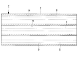
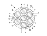
- the medical tube 2 includes a tube main body 7 made of a flexible material and a support wire (support member) 8 fixed to the tube main body 7.
- the tube body 7 is constituted by a multi-lumen tube including a plurality of lumens 9 penetrating in the longitudinal direction, and the drive wires 6 are passed through the lumens 9.
- the tube body 7 includes seven lumens 9, and FIG. 2 is a longitudinal section in a plane that passes through the central axis of the three lumens 9.
- FIG. 1 is a longitudinal section in a plane that passes through the central axis of the three lumens 9.
- the support wire 8 is a single wire-like member having a circular cross section and made of a material having a higher Young's modulus than the tube body 7, for example, a metal, a resin, or the like.
- the tube body 7 is provided with a through hole (support member lumen) 10 through which the support wire 8 passes.
- the through holes 10 are arranged at six positions at intervals in the circumferential direction at positions close to the outer peripheral surface of the tube body 7.
- the diameter of the through hole 10 is substantially the same as the outer diameter of the support wire 8 that penetrates the through hole 10. It is desirable that the outer surface of the support wire 8 is in close contact with the inner surface of the through hole 10 by inserting and arranging the support wire 8 in the through hole 10.
- the support wire 8 is fixed in the through hole 10 of the tube body 7 with an adhesive.
- the fixing position may be fixed over the entire length, or may be fixed only at both ends.
- the lumen 9 of the tube body 7 has a circular cross-sectional shape, and the inner diameter dimension thereof is larger than the outer diameter dimension of the support wire 8. Further, the outer diameter dimension of the drive wire 6 is formed larger than the outer diameter dimension of the support wire 8. Further, the through hole 10 for the support wire 8 is disposed between the lumens 9 adjacent to each other in the circumferential direction of the tube body 7.
- the operator inserts the insertion portion 2 of the flexible treatment tool 1 through the forceps channel of the endoscope inserted into the body cavity of the patient. Is inserted from the side of the movable part 4 at the tip, and the movable part 4 is made to face the affected part while observing an image acquired by the endoscope on the monitor.
- the forceps channel provided in the endoscope is also bent similarly. ing. Therefore, in order to insert the insertion portion 2 of the flexible treatment instrument 1 through the forceps channel, it is necessary to insert the insertion portion 2 while curving it following the shape of the forceps channel.
- the medical tube 2 constituting the insertion portion of the flexible treatment instrument 1 includes a support wire 8 fixed along the longitudinal direction of the tube body 7, and the Young's modulus of the support wire 8 is a tube. It is set to be larger than the Young's modulus of the main body 7. Therefore, the compression rigidity of the medical tube 2 is set sufficiently higher than the compression rigidity of the tube body 7. Further, the bending rigidity with respect to the bending acting on the medical tube 2 is set sufficiently higher than that in the case where the support wire 8 is not provided.
- the medical tube 2 constituting the insertion portion, the tube main body 7 of the medical tube 2, and the tube main body 7 are formed.
- the entire insertion portion 2 is bent by twisting the lumen 9 and the through hole 10, and the drive wire 6 passing through the lumen 9 and the support wire 8 passing through the through hole 10.
- the operator generates a driving force in the drive unit 5 by operating an operation unit (not shown) and pulls one of the drive wires 6.
- the driving force applied to the drive wire 6 is transmitted to the movable part 4 as the tension of the drive wire 6, and the movable part 4 is operated.
- the tube main body 7 is positioned in the vicinity of the lumen 9 of the towed drive wire 6.
- a compression force acts.
- the compression rigidity is enhanced by the support wire 8 fixed to the tube body 7, compression and bending of the tube body 7 due to the pulling of the drive wire 6 is suppressed.
- the cross-sectional shape of the drive wire 6 is set larger than that of the support wire 8, the rigidity of the drive wire 6 that drives the movable portion 4 can be increased. There is an advantage that the response during driving can be improved.
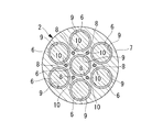
- the through-hole 10 which penetrates the support wire 8 is arrange
- the support wire 8 is arrange
- the support wire 8 can be disposed as radially inward as possible while ensuring a sufficient thickness of the tube body 7. Thereby, the diameter of the medical tube 2 can be reduced.
- the support wire 8 is comprised with the single wire, there exists an advantage that it can comprise at low cost compared with the case where it comprises with a strand wire. Moreover, rigidity can be improved by comprising with a solid single wire.
- the number of support wires 8 is preferably greater than the number of drive wires 6. In this way, bending of the tube body 7 can be suppressed by the large number of support wires 8. Further, the position of the support wire 8 is preferably in the vicinity of the outer periphery of the tube body 7 as shown in FIGS. 3 and 4, but as shown in FIGS. 5 and 6, there is a space between the lumens 9. You may arrange
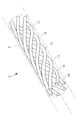
- rumen 11 is the longitudinal axis of the tube main body 7, as FIG. 7 shows. It may be formed in a spiral shape having a constant pitch and a constant radius in one direction.
- FIG. 7 shows only the lumen 11 provided in the tube main body 7.
- the through-hole 10 through which the support wire 8 passes may be provided straight along the longitudinal direction of the tube body 7 or twisted in the same direction as the lumen 9 for the drive wire 6. Also good.
- the pitch when the support wire 8 is twisted may be different from the pitch of the lumen 9 for the drive wire 6 but is preferably the same.
- the tube body 7 is provided with the through-hole 10 that allows the support wire 8 to pass therethrough.
- a groove 12 that accommodates the support wire 8 is provided. It is good also as fixing with the fixing materials, such as an adhesive agent or resin, in the state which provided and the support wire 8 was accommodated in this groove
- the medical tube 2 may include an outer tube that covers the tube body 7.
- the compression rigidity can be improved while ensuring flexibility.
- a tube made of a braided body as the exterior tube, it is possible to improve torque transmission while ensuring flexibility.
- a hydrophilic coated tube or a PTFE tube as the outer tube, it is possible to reduce surface friction and improve electrical insulation.
- the tube body 7 may be made of an electrically insulating material, and the support wire 8 may be made of a conductive material. By doing so, it is possible to supply power and transmit electric signals from the proximal end side of the insertion portion 2 to the movable portion 4 on the distal end side through the support wire 8 insulated by the tube body 7. Since there is no need to prepare a separate electric wiring, there is an advantage that the diameter of the insertion portion 2 can be reduced.
Landscapes
- Health & Medical Sciences (AREA)
- Surgery (AREA)
- Life Sciences & Earth Sciences (AREA)
- Medical Informatics (AREA)
- Animal Behavior & Ethology (AREA)
- Engineering & Computer Science (AREA)
- Biomedical Technology (AREA)
- Heart & Thoracic Surgery (AREA)
- Ophthalmology & Optometry (AREA)
- Molecular Biology (AREA)
- Nuclear Medicine, Radiotherapy & Molecular Imaging (AREA)
- General Health & Medical Sciences (AREA)
- Public Health (AREA)
- Veterinary Medicine (AREA)
- Media Introduction/Drainage Providing Device (AREA)
- Surgical Instruments (AREA)
- Endoscopes (AREA)
Abstract
L'invention concerne un instrument de traitement flexible configuré de telle sorte qu'une section mobile disposée à l'extrémité distale d'une section d'insertion flexible peut être actionnée ou commandée avec une efficacité accrue lorsque l'opération ou la commande est réalisée sur le côté d'extrémité de base de la section d'insertion par un élément de transmission de puissance d'entraînement allongé. Cet instrument de traitement flexible (1) comprend : une section d'insertion flexible allongée (2) ; une section mobile (4) disposée à l'extrémité distale de la section d'insertion (2) ; une section d'entraînement (5) disposée à l'extrémité proximale de la section d'insertion (2) ; et un élément de transmission de puissance d'entraînement allongé pour transmettre la puissance de la section d'entraînement (5) à la section mobile (4). La section d'insertion (2) comprend un tube médical (2) pourvu d'une lumière à travers laquelle l'élément de transmission de puissance d'entraînement est inséré longitudinalement. Le tube médical (2) comprend : un corps de tube allongé (7) dans lequel la lumière est formée ; et un ou plusieurs éléments de support en forme de fils fixés de manière longitudinale dans le corps de tube (7) et ayant un module de Young supérieur à celui du corps de tube.
Priority Applications (2)
| Application Number | Priority Date | Filing Date | Title |
|---|---|---|---|
| PCT/JP2016/057587 WO2017154172A1 (fr) | 2016-03-10 | 2016-03-10 | Instrument de traitement flexible et tube médical |
| JP2018503946A JPWO2017154172A1 (ja) | 2016-03-10 | 2016-03-10 | 軟性処置具および医療用チューブ |
Applications Claiming Priority (1)
| Application Number | Priority Date | Filing Date | Title |
|---|---|---|---|
| PCT/JP2016/057587 WO2017154172A1 (fr) | 2016-03-10 | 2016-03-10 | Instrument de traitement flexible et tube médical |
Publications (1)
| Publication Number | Publication Date |
|---|---|
| WO2017154172A1 true WO2017154172A1 (fr) | 2017-09-14 |
Family
ID=59790296
Family Applications (1)
| Application Number | Title | Priority Date | Filing Date |
|---|---|---|---|
| PCT/JP2016/057587 Ceased WO2017154172A1 (fr) | 2016-03-10 | 2016-03-10 | Instrument de traitement flexible et tube médical |
Country Status (2)
| Country | Link |
|---|---|
| JP (1) | JPWO2017154172A1 (fr) |
| WO (1) | WO2017154172A1 (fr) |
Citations (7)
| Publication number | Priority date | Publication date | Assignee | Title |
|---|---|---|---|---|
| JPH05345031A (ja) * | 1992-06-16 | 1993-12-27 | Tougou Medeikitsuto Kk | カテーテル |
| WO2007096951A1 (fr) * | 2006-02-21 | 2007-08-30 | Olympus Medical Systems Corp. | Système d'endoscope et instrument chirurgical |
| JP2009530051A (ja) * | 2006-03-23 | 2009-08-27 | ボストン サイエンティフィック リミテッド | 医療デバイスおよびシステム |
| JP2012034971A (ja) * | 2010-08-10 | 2012-02-23 | Japan Lifeline Co Ltd | カテーテル |
| WO2013011771A1 (fr) * | 2011-07-15 | 2013-01-24 | オリンパスメディカルシステムズ株式会社 | Instrument d'introduction |
| JP2014236788A (ja) * | 2013-06-06 | 2014-12-18 | 日本ライフライン株式会社 | 電極カテーテルシステム |
| WO2015093602A1 (fr) * | 2013-12-20 | 2015-06-25 | オリンパス株式会社 | Élément de guidage pour manipulateur flexible, et manipulateur flexible |
-
2016
- 2016-03-10 JP JP2018503946A patent/JPWO2017154172A1/ja active Pending
- 2016-03-10 WO PCT/JP2016/057587 patent/WO2017154172A1/fr not_active Ceased
Patent Citations (7)
| Publication number | Priority date | Publication date | Assignee | Title |
|---|---|---|---|---|
| JPH05345031A (ja) * | 1992-06-16 | 1993-12-27 | Tougou Medeikitsuto Kk | カテーテル |
| WO2007096951A1 (fr) * | 2006-02-21 | 2007-08-30 | Olympus Medical Systems Corp. | Système d'endoscope et instrument chirurgical |
| JP2009530051A (ja) * | 2006-03-23 | 2009-08-27 | ボストン サイエンティフィック リミテッド | 医療デバイスおよびシステム |
| JP2012034971A (ja) * | 2010-08-10 | 2012-02-23 | Japan Lifeline Co Ltd | カテーテル |
| WO2013011771A1 (fr) * | 2011-07-15 | 2013-01-24 | オリンパスメディカルシステムズ株式会社 | Instrument d'introduction |
| JP2014236788A (ja) * | 2013-06-06 | 2014-12-18 | 日本ライフライン株式会社 | 電極カテーテルシステム |
| WO2015093602A1 (fr) * | 2013-12-20 | 2015-06-25 | オリンパス株式会社 | Élément de guidage pour manipulateur flexible, et manipulateur flexible |
Also Published As
| Publication number | Publication date |
|---|---|
| JPWO2017154172A1 (ja) | 2019-01-10 |
Similar Documents
| Publication | Publication Date | Title |
|---|---|---|
| US11730551B2 (en) | Steerable medical device with strain relief elements | |
| JP6261612B2 (ja) | 軟性マニピュレータ用ガイド部材および軟性マニピュレータ | |
| JP5981080B1 (ja) | 内視鏡用湾曲管及びこの内視鏡用湾曲管を具備した内視鏡 | |
| US10149608B2 (en) | Bending portion for endoscope and endoscope including bending portion for endoscope | |
| CN113812900A (zh) | 包括铰接式弯曲区段本体的内窥镜 | |
| JP5711434B1 (ja) | 内視鏡 | |
| WO2016194249A1 (fr) | Manipulateur médical | |
| JP5114179B2 (ja) | 内視鏡用バイポーラ型高周波処置具 | |
| WO2016056417A1 (fr) | Endoscope | |
| EP3257465A1 (fr) | Manipulateur | |
| CN113873948B (zh) | 医疗工具定位装置、系统以及使用和制造方法 | |
| JP6271098B1 (ja) | 医療用オーバーチューブ | |
| JP6296869B2 (ja) | 処置具および手術システム | |
| JPWO2017175373A1 (ja) | 軟性マニピュレータ | |
| JP6637991B2 (ja) | 医療機器 | |
| JPWO2017154172A1 (ja) | 軟性処置具および医療用チューブ | |
| JP2007289593A5 (fr) | ||
| WO2019207676A1 (fr) | Instrument de traitement et système de traitement | |
| US11660421B2 (en) | Medical manipulator and medical device | |
| WO2018216109A1 (fr) | Manipulateur souple | |
| WO2020021718A1 (fr) | Endoscope | |
| JPWO2021176719A5 (fr) | ||
| JP2016511120A (ja) | 弦面を備えた多導体ガイドワイヤ | |
| JPH11267091A (ja) | 内視鏡の挿入部 | |
| JP2013172781A (ja) | 管状器具 |
Legal Events
| Date | Code | Title | Description |
|---|---|---|---|
| ENP | Entry into the national phase |
Ref document number: 2018503946 Country of ref document: JP Kind code of ref document: A |
|
| NENP | Non-entry into the national phase |
Ref country code: DE |
|
| 121 | Ep: the epo has been informed by wipo that ep was designated in this application |
Ref document number: 16893501 Country of ref document: EP Kind code of ref document: A1 |
|
| 122 | Ep: pct application non-entry in european phase |
Ref document number: 16893501 Country of ref document: EP Kind code of ref document: A1 |