WO2017154178A1 - Système et procédé de communication sans fil, et dispositif sans fil - Google Patents
Système et procédé de communication sans fil, et dispositif sans fil Download PDFInfo
- Publication number
- WO2017154178A1 WO2017154178A1 PCT/JP2016/057643 JP2016057643W WO2017154178A1 WO 2017154178 A1 WO2017154178 A1 WO 2017154178A1 JP 2016057643 W JP2016057643 W JP 2016057643W WO 2017154178 A1 WO2017154178 A1 WO 2017154178A1
- Authority
- WO
- WIPO (PCT)
- Prior art keywords
- signal
- frequency
- antenna
- living body
- tag device
- Prior art date
- Legal status (The legal status is an assumption and is not a legal conclusion. Google has not performed a legal analysis and makes no representation as to the accuracy of the status listed.)
- Ceased
Links
Images










Classifications
-
- A—HUMAN NECESSITIES
- A61—MEDICAL OR VETERINARY SCIENCE; HYGIENE
- A61B—DIAGNOSIS; SURGERY; IDENTIFICATION
- A61B5/00—Measuring for diagnostic purposes; Identification of persons
- A61B5/07—Endoradiosondes
- A61B5/073—Intestinal transmitters
-
- A—HUMAN NECESSITIES
- A61—MEDICAL OR VETERINARY SCIENCE; HYGIENE
- A61B—DIAGNOSIS; SURGERY; IDENTIFICATION
- A61B5/00—Measuring for diagnostic purposes; Identification of persons
- A61B5/07—Endoradiosondes
-
- A—HUMAN NECESSITIES
- A61—MEDICAL OR VETERINARY SCIENCE; HYGIENE
- A61B—DIAGNOSIS; SURGERY; IDENTIFICATION
- A61B90/00—Instruments, implements or accessories specially adapted for surgery or diagnosis and not covered by any of the groups A61B1/00 - A61B50/00, e.g. for luxation treatment or for protecting wound edges
- A61B90/90—Identification means for patients or instruments, e.g. tags
- A61B90/98—Identification means for patients or instruments, e.g. tags using electromagnetic means, e.g. transponders
-
- H—ELECTRICITY
- H04—ELECTRIC COMMUNICATION TECHNIQUE
- H04W—WIRELESS COMMUNICATION NETWORKS
- H04W4/00—Services specially adapted for wireless communication networks; Facilities therefor
- H04W4/80—Services using short range communication, e.g. near-field communication [NFC], radio-frequency identification [RFID] or low energy communication
Definitions
- the present invention relates to a wireless communication system, a wireless communication method, and a wireless device.
- a wireless communication system is known that is introduced into a living body and includes a first wireless device having an antenna and a second wireless device that communicates with the first wireless device via the antenna (for example, Patent Document 1).
- wireless apparatus is not only when a 1st radio
- the antenna When the first wireless device is located inside the living body, the antenna often comes into contact with a liquid inside the living body (for example, digestive fluid). On the other hand, when the first wireless device is located outside the living body, the antenna often comes into contact with air. Moreover, the dielectric constant of the liquid inside the living body is different from the dielectric constant of air.
- the resonance frequency of the antenna when the first wireless device is located inside the living body tends to be different from the resonance frequency of the antenna when the first wireless device is located outside the living body. Therefore, between the case where the first wireless device is located inside the living body and the case where the first wireless device is located outside the living body, between the first wireless device and the second wireless device. There was a possibility that communication could not be performed.
- One of the objects of the present invention is to communicate even when the wireless device is located inside or outside the living body.
- a wireless communication system is A first wireless device introduced into the living body and having an antenna; A second wireless device communicating with the first wireless device via the antenna.
- the wireless communication system is When the first wireless device is located outside the living body, the first frequency is used for communication via the antenna between the first wireless device and the second wireless device, When the first wireless device is located inside the living body, a second frequency lower than the first frequency is used for the communication.
- a wireless communication method in another aspect, includes: A first wireless device introduced into the living body and having an antenna; The present invention is applied to a wireless communication system including the first wireless device and a second wireless device that communicates via the antenna.
- the wireless communication method is When the first wireless device is located outside the living body, the first frequency is used for communication via the antenna between the first wireless device and the second wireless device, When the first wireless device is located inside the living body, a second frequency lower than the first frequency is used for the communication.
- the wireless device is introduced into the living body and has an antenna.
- the wireless device is A detection unit for detecting whether or not the wireless device is located inside the living body; A transmitter for transmitting a signal via the antenna; When it is detected that the wireless device is located outside the living body, the frequency of the signal is controlled to the first frequency. On the other hand, when it is detected that the wireless device is located inside the living body, the signal A control unit that controls the frequency of the second frequency lower than the first frequency; Is provided.
- the wireless device is a device as a second wireless device that is introduced into the living body and communicates with the first wireless device having an antenna via the antenna.
- the wireless device is A transmitter for transmitting a signal;
- the frequency of the signal is controlled to the first frequency, while when the first wireless device is located inside the living body, the signal A control unit that controls the frequency of the second frequency lower than the first frequency; Is provided.
- FIG. 2 is a sequence diagram illustrating an example of operation of the wireless communication system in FIG. 1.
- FIG. 2 is a sequence diagram illustrating an example of operation of the wireless communication system in FIG. 1.
- FIG. 2 is a sequence diagram showing an example of operation
- the wireless communication system 1 includes a reader device 10 and a tag device 20.
- the wireless communication system 1 is an RFID (Radio Frequency Identifier) system.
- the wireless communication system 1 may be a wireless communication system different from the RFID system.
- the wireless communication system 1 may perform communication according to a predetermined wireless communication method.
- the wireless communication method is a Bluetooth Low Energy (BLE) method, an ANT method, an ANT + method, or a ZigBee method.
- BLE Bluetooth Low Energy
- ANT + an ANT + method
- ZigBee a ZigBee method
- BLE may be expressed as Bluetooth 4.0, Bluetooth Smart, or Bluetooth Smart Ready.
- the tag device 20 may be represented as an RFID, an RFID tag, a wireless tag, or an IC (Integrated Circuit) tag.
- the tag device 20 corresponds to a first wireless device.
- the reader device 10 corresponds to a second wireless device.
- the tag device 20 is configured to be introduced into a living body (in this example, a human body). In this example, the tag device 20 is configured to be introduced into the inside of a living body by oral means.
- the tag device 20 is attached to a denture.
- the tag device 20 may constitute at least a part of the denture.
- the denture is a local denture (in other words, a partial denture).
- the denture may be a complete denture (in other words, a full denture).
- the tag device 20 may be attached to a sensor that detects a physical quantity, or may constitute at least a part of the sensor.
- the tag device 20 may be attached to a preparation such as a capsule or a tablet, or may constitute at least a part of the preparation.
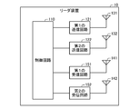
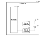
- the reader device 10 includes a control circuit 110, a first transmission circuit 121, a second transmission circuit 122, a first transmission antenna 131, and a second transmission antenna 132. , A first receiving antenna 141, a second receiving antenna 142, a first receiving circuit 151, and a second receiving circuit 152.
- the first transmission circuit 121 and the second transmission circuit 122 correspond to a transmission unit.
- the first receiving circuit 151 and the second receiving circuit 152 correspond to a receiving unit.
- the control circuit 110 corresponds to a control unit.
- At least a part of the reader device 10 is configured by an LSI (Large Scale Integration) circuit.
- LSI Large Scale Integration
- at least a part of the reader device 10 may be configured by a programmable logic circuit (for example, PLD or FPGA).
- PLD is an abbreviation for Programmable Logic Device.
- FPGA is an abbreviation for Field-Programmable Gate Array.
- the reader device 10 may include a processing device and a storage device, and at least a part of the functions of the reader device 10 may be realized by the processing device executing a program stored in the storage device.
- the processing device may include a CPU (Central Processing Unit), an MPU (Micro Processing Unit), or a DSP (Digital Signal Processor).
- the storage device may include a RAM (Random Access Memory), a semiconductor memory, or an organic memory.
- the reader device 10 may constitute at least a part of a mobile phone, a smartphone, a personal computer, or the like.
- the reader device 10 may be connected to a mobile phone, a smartphone, a personal computer, or the like.
- the first transmission circuit 121 transmits a request signal whose carrier wave has the first frequency (in other words, the first request signal) via the first transmission antenna 131.
- the first frequency is included in a first frequency band among a plurality of frequency bands called an ISM (Industry-Science-Medical) band.
- the first frequency is included in the 5.8 GHz band (for example, 5.725 GHz to 5.875 GHz).
- the request signal is a signal that requests the tag device 20 to transmit information.
- the request signal includes a first signal configuration unit, a second signal configuration unit, and a third signal configuration unit that are continuous in the time axis.
- Each of the first signal component and the third signal component is an unmodulated wave (in other words, a carrier wave).
- the second signal component is a modulated wave (in other words, a radio wave in which a carrier wave is modulated).
- the second signal component represents specific information.
- the identification information identifies information that requests the tag device 20 to transmit.
- the first signal configuration unit, the second signal configuration unit, and the third signal configuration unit have a predetermined first time length, second time length, and third signal length. Each has a length of time.
- the second transmission circuit 122 transmits a request signal whose carrier wave has the second frequency (in other words, the second request signal) via the second transmission antenna 132.
- the second frequency is lower than the first frequency.
- the second frequency is lower than half of the first frequency.
- the second frequency is included in a second frequency band lower than the first frequency band among a plurality of frequency bands called an ISM band.
- the second frequency is included in the 2.45 GHz band (for example, 2.4 GHz to 2.5 GHz).
- the first receiving circuit 151 receives a response signal (in other words, a first response signal) having a carrier wave having a first frequency via the first receiving antenna 141.
- the response signal represents information specified by the specific information (in other words, response information).
- the response information includes at least one of information stored in the tag device 20 and information generated by the tag device 20.
- the response signal is a signal modulated by reflecting at least a part of the third signal component of the request signal by the tag device 20.
- the second receiving circuit 152 receives a response signal (in other words, a second response signal) in which the carrier wave has the second frequency via the second receiving antenna 142.
- the control circuit 110 controls the first transmission circuit 121 so that the first transmission circuit 121 starts transmission of the request signal. Furthermore, the control circuit 110 controls the first transmission circuit 121 so that the first transmission circuit 121 ends the transmission of the request signal. The control circuit 110 controls the second transmission circuit 122 similarly to the first transmission circuit 121.
- the control circuit 110 controls the first reception circuit 151 so that the first reception circuit 151 starts to wait for reception of the response signal. Further, the control circuit 110 controls the first reception circuit 151 so that the first reception circuit 151 ends the waiting for reception of the response signal. The control circuit 110 controls the second reception circuit 152 in the same manner as the first reception circuit 151.
- the control circuit 110 causes the first transmission circuit 121 and the second transmission circuit 122 to simultaneously start transmitting the request signal, and causes the first reception circuit 151 and the second reception circuit 152 to At the same time, it waits for reception of a response signal.
- the control circuit 110 controls the first receiving circuit 151 and the second receiving circuit 152 so that standby for receiving the response signal starts almost simultaneously with the start of transmission of the request signal. Note that the waiting for reception of the response signal may be started after a predetermined delay time has elapsed from the start of transmission of the request signal.
- the control circuit 110 also includes the first transmission circuit 121 and the second transmission circuit 121 so that the transmission of the request signal by the first transmission circuit 121 and the transmission of the request signal by the second transmission circuit 122 are alternately performed.
- the transmission circuit 122 may be controlled.
- control circuit 110 waits for reception of the response signal by the first reception circuit 151 during at least a part of the period during which the request signal is transmitted by the first transmission circuit 121. 1 receiving circuit 151 is controlled. Further, in this case, the control circuit 110 waits for reception of the response signal by the second reception circuit 152 during at least a part of the period during which the request signal is transmitted by the second transmission circuit 122. The second receiving circuit 152 is controlled.
- control circuit 110 has the strength of the first response signal received by the first reception circuit 151 and the second response signal received by the second reception circuit 152. Get response information based only on the larger one.
- the signal strength is a parameter that increases as at least one of signal power, signal amplitude, or signal power and signal amplitude increases.
- the control circuit 110 uses the tag based on the strength of the first response signal received by the first receiving circuit 151 and the strength of the second response signal received by the second receiving circuit 152. It may be detected that the device 20 has been introduced from outside the living body into the living body. In this case, the control circuit 110 changes the state where the strength of the first response signal is greater than the strength of the second response signal to a state where the strength of the second response signal is greater than the strength of the first response signal. In this case, it may be detected that the tag device 20 has been introduced into the living body from the outside of the living body.
- control circuit 110 uses the tag based on the strength of the first response signal received by the first receiving circuit 151 and the strength of the second response signal received by the second receiving circuit 152. It may be detected that the device 20 is discharged from the inside of the living body to the outside of the living body. In this case, the control circuit 110 changes the state where the strength of the second response signal is greater than the strength of the first response signal to a state where the strength of the first response signal is greater than the strength of the second response signal. In this case, it may be detected that the tag device 20 is discharged from the inside of the living body to the outside of the living body.
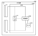
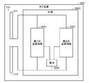
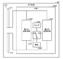
- the tag device 20 includes an antenna 210 and an IC unit 220.
- the IC unit 220 corresponds to a transmission unit.
- At least a part of the tag device 20 is configured by an LSI circuit.
- at least a part of the tag device 20 may be configured by a programmable logic circuit.
- the tag device 20 may include a processing device and a storage device, and at least a part of the functions of the tag device 20 may be realized by the processing device executing a program stored in the storage device.
- the antenna 210 includes a first antenna configuration unit 211 and a second antenna configuration unit 212.
- the first antenna configuration unit 211 and the second antenna configuration unit 212 configure a dipole antenna.
- the first antenna configuration unit 211 and the second antenna configuration unit 212 have a meander shape.
- the 1st antenna structure part 211 and the 2nd antenna structure part 212 may have a shape (for example, linear shape) different from a meander shape.
- the resonance frequency of the antenna 210 substantially matches the first frequency when the antenna 210 is in contact with air. Further, in this example, the resonance frequency of the antenna 210 substantially matches the second frequency when the antenna 210 is in contact with a liquid inside the living body (in this example, digestive fluid such as saliva).
- the antenna 210 may be an antenna different from the dipole antenna (for example, a loop antenna, a plate antenna, a planar antenna, etc.).
- the IC unit 220 is connected to the first antenna configuration unit 211 and the second antenna configuration unit 212.
- the IC unit 220 includes a switching element 221 and a modulation circuit 222.
- the tag device 20 is a passive type.
- the IC unit 220 operates due to a potential difference generated between the first antenna configuration unit 211 and the second antenna configuration unit 212 when the antenna 210 receives a signal.
- the IC unit 220 includes a rectifier and a capacitor (not shown), and at least part of a period during which the first signal component of the request signal is received, the first antenna component 211 and the first antenna.
- the current generated between the two antenna components 212 is rectified by a rectifier and stored in a capacitor.
- the IC unit 220 demodulates the second signal component by using the electric power stored in the capacitor during at least a part of the period during which the second signal component of the request signal is received. .
- the IC unit 220 acquires specific information based on the demodulated signal.
- the switching element 221 short-circuits (in other words, connects) the first antenna configuration unit 211 and the second antenna configuration unit 212, and the first antenna configuration unit 211 and the second antenna configuration unit 212. Is switched (in other words, not connected) to the blocked state, and the state of the switching element 221 is switched.
- the reflection intensity when the state of the switching element 221 is in a short circuit state is larger than the reflection intensity when the state of the switching element 221 is in a cutoff state.
- the reflection intensity is an intensity of a signal reflected by the tag device 20 among signals received by the antenna 210 (in other words, a signal transmitted by the tag device 20).
- the power absorbed by the IC unit 220 among the power of the signal received by the antenna 210 is when the state of the switching element 221 is a short circuit state. Bigger than.
- the modulation circuit 222 uses the power stored in the capacitor in at least a part of the period during which the third signal component of the request signal is received, so that the information specified by the specific information (in other words, The state of the switching element 221 is controlled based on the response information.
- the modulation circuit 222 controls the state of the switching element 221 to be associated with the value of the bit for each of at least one bit representing the response information.
- the short-circuit state is associated with 1 as the bit value
- the cutoff state is associated with 0 as the bit value.
- the short circuit state may be associated with 0 as a bit value
- the cutoff state may be associated with 1 as a bit value.
- the response information includes information stored in advance by the IC unit 220.
- the response information may include an identifier that identifies the tag device 20.
- the tag device 20 includes a sensor that detects a physical quantity
- the response information is replaced with information stored in the IC unit 220 in advance or in addition to information stored in the IC unit 220 in advance.
- Information representing a physical quantity detected by the sensor may be included.
- the physical quantity is temperature, humidity, illuminance, pH, acceleration, angular velocity, pressure, or the concentration of an object.
- the object is digestive fluid (for example, saliva, gastric fluid, intestinal fluid, or pancreatic fluid), blood, resident bacteria, or infectious substance (for example, bacteria or virus).
- the IC unit 220 modulates the request signal received by the antenna 210 in accordance with an amplitude modulation (AM) method and transmits the modulated request signal as a response signal.
- the tag device 20 transmits a response signal representing response information in accordance with the backscatter method.
- the IC unit 220 may perform modulation according to a modulation scheme different from the AM scheme.
- the modulation method may be a frequency modulation (FM) method or a phase modulation (PM) method.
- the modulation method may be a combination of at least two of the AM method, the FM method, and the PM method.
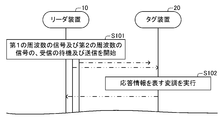
- the reader device 10 transmits a request signal whose carrier wave has the first frequency (in other words, the first request signal) and a request signal whose carrier wave has the second frequency (in other words, the second request signal). Transmission, the carrier wave waits for reception of a response signal having the first frequency (in other words, the first response signal), and a response signal in which the carrier wave has the second frequency (in other words, the second signal). Is started (step S101 in FIG. 4).
- the tag device 20 receives the first request signal and the second request signal. According to the above assumption, since the antenna 210 is in contact with air, the resonance frequency of the antenna 210 substantially matches the first frequency. Accordingly, the strength of the first request signal received by the antenna 210 is greater than the strength of the second request signal received by the antenna 210.
- the tag device 20 rectifies a current generated between the first antenna configuration unit 211 and the second antenna configuration unit 212 during at least a part of a period during which the first signal configuration unit of the request signal is received. Is stored in the capacitor by rectification.
- the tag device 20 demodulates the second signal component by using the electric power stored in the capacitor during at least a part of the period during which the second signal component of the request signal is received.
- the specific information is acquired based on the demodulated signal.
- the tag device 20 is received by the antenna 210 based on the response information by using the power stored in the capacitor during at least part of the period during which the third signal component of the request signal is received.
- the request signal is modulated, and the modulated request signal is transmitted as a response signal (step S102 in FIG. 4). In this way, in this example, the tag device 20 transmits a response signal representing response information according to the backscatter method.
- the response signal transmitted by the antenna 210 includes a first response signal whose carrier wave has a first frequency (in other words, a first component) and a second response whose carrier wave has a second frequency.
- Signal in other words, the second component.
- the reader device 10 receives the response signal transmitted by the tag device 20.
- the reader device 10 acquires response information based only on the higher one of the first response signal and the second response signal included in the received response signal. Therefore, according to the above assumption, the reader device 10 acquires response information based only on the first response signal out of the first response signal and the second response signal included in the received response signal. .
- the tag device 20 is located inside the living body.
- the antenna 210 of the tag device 20 is in contact with the liquid inside the living body (in this example, saliva).
- the reader device 10 starts transmission of the first request signal and transmission of the second request signal, and waits for reception of the first response signal. Then, waiting for reception of the second response signal is started (step S101 in FIG. 5).
- the tag device 20 receives the first request signal and the second request signal. According to the above assumption, since the antenna 210 is in contact with the liquid inside the living body, the resonance frequency of the antenna 210 substantially matches the second frequency. Accordingly, the strength of the second request signal received by the antenna 210 is greater than the strength of the first request signal received by the antenna 210.
- the tag device 20 rectifies a current generated between the first antenna configuration unit 211 and the second antenna configuration unit 212 during at least a part of a period during which the first signal configuration unit of the request signal is received. Is stored in the capacitor by rectification.
- the tag device 20 demodulates the second signal component by using the electric power stored in the capacitor during at least a part of the period during which the second signal component of the request signal is received.
- the specific information is acquired based on the demodulated signal.
- the tag device 20 is received by the antenna 210 based on the response information by using the power stored in the capacitor during at least part of the period during which the third signal component of the request signal is received.
- the request signal is modulated, and the modulated request signal is transmitted as a response signal (step S102 in FIG. 5). In this way, in this example, the tag device 20 transmits a response signal representing response information according to the backscatter method.
- the response signal transmitted by the antenna 210 includes a first response signal whose carrier wave has a first frequency (in other words, a first component) and a second response whose carrier wave has a second frequency.
- Signal in other words, the second component.
- the resonance frequency of the antenna 210 substantially matches the second frequency, so the strength of the second response signal is greater than the strength of the first response signal.
- the reader device 10 receives the response signal transmitted by the tag device 20.
- the reader device 10 acquires response information based only on the higher one of the first response signal and the second response signal included in the received response signal. Therefore, according to the above assumption, the reader device 10 acquires response information based only on the second response signal out of the first response signal and the second response signal included in the received response signal. .
- the wireless communication system 1 when the tag device 20 is located outside the living body, the communication between the tag device 20 and the reader device 10 via the antenna 210 is performed in the first communication. A frequency of 1 is used. Further, when the tag device 20 is located inside the living body, the wireless communication system 1 uses a second frequency lower than the first frequency for communication via the antenna 210 between the tag device 20 and the reader device 10. Is used.
- the reader device 10 can communicate with the tag device 20 via the antenna 210 of the tag device 20.
- the reader device 10 of the first embodiment receives a signal having the first frequency and a signal having the second frequency.
- the reader device 10 can receive a signal having the first frequency.
- the reader device 10 can receive a signal having the second frequency. Therefore, the reader device 10 can communicate with the tag device 20 via the antenna 210 of the tag device 20 regardless of whether the tag device 20 is located inside or outside the living body.
- the reader device 10 of the first embodiment transmits a signal having the first frequency and a signal having the second frequency.
- the tag device 20 when the tag device 20 is located outside the living body, the tag device 20 can receive a signal having the first frequency. Further, when the tag device 20 is located inside the living body, the tag device 20 can receive a signal having the second frequency. Therefore, regardless of whether the tag device 20 is located inside or outside the living body, the tag device 20 can communicate with the reader device 10 via the antenna 210 included in the tag device 20.
- the tag device 20 of the first embodiment modulates the signal transmitted by the reader device 10 and transmits the modulated signal.
- the reader device 10 can receive a signal having the first frequency.
- the reader device 10 can receive a signal having the second frequency. Therefore, the reader device 10 can communicate with the tag device 20 via the antenna 210 of the tag device 20 regardless of whether the tag device 20 is located inside or outside the living body.
- the wireless communication system 1 uses a frequency included in a 2.45 GHz band (for example, 2.4 GHz to 2.5 GHz) as the first frequency, and a 900 MHz band (for example, 915 MHz to 915 MHz) as the second frequency. 955 MHz) may be used.
- a 2.45 GHz band for example, 2.4 GHz to 2.5 GHz
- a 900 MHz band for example, 915 MHz to 915 MHz
- 955 MHz may be used.
- the wireless communication system 1 uses a frequency included in the 5.8 GHz band (for example, 5.725 GHz to 5.875 GHz) as the first frequency, and the 900 MHz band (for example, 915 MHz to 915 MHz) as the second frequency. 955 MHz) may be used.
- 5.8 GHz band for example, 5.725 GHz to 5.875 GHz
- 900 MHz band for example, 915 MHz to 915 MHz
- 955 MHz may be used.
- the wireless communication system 1 uses a frequency included in a 60 GHz band (for example, 57 GHz to 66 GHz) as the first frequency, and a 5.8 GHz band (for example, 5.725 GHz to 5.725) as the second frequency. 875 GHz) may be used.
- a frequency included in a 60 GHz band for example, 57 GHz to 66 GHz
- a 5.8 GHz band for example, 5.725 GHz to 5.725
- 875 GHz 875 GHz
- the wireless communication system 1 uses a frequency included in a 24 GHz band (for example, 24 GHz to 24.25 GHz) as the first frequency, and a 5.8 GHz band (for example, 5.725 GHz to The frequency included in 5.875 GHz may be used.
- a 24 GHz band for example, 24 GHz to 24.25 GHz
- a 5.8 GHz band for example, 5.725 GHz to The frequency included in 5.875 GHz may be used.
- the tag device 20 may include a changing unit that changes the resonance frequency of the antenna 210.
- the changing unit may include a first extension antenna configuration unit, a second extension antenna configuration unit, a first switching element, and a second switching element.
- the first extension antenna component is connected to the first antenna component 211 via the first switching element.
- the first switching element cuts off the state in which the first antenna component 211 and the first extension antenna component are connected, and the first antenna component 211 and the first extension antenna component.
- the state of the first switching element is switched to the state.
- the second extension antenna component is connected to the second antenna component 212 via the second switching element.
- the second switching element cuts off the state in which the second antenna component 212 and the second extension antenna component are connected, and the second antenna component 212 and the second extension antenna component.
- the state of the second switching element is switched to the state.
- the ratio between the first frequency and the second frequency can be changed to a ratio different from the value corresponding to the ratio between the dielectric constant of the air and the dielectric constant of the liquid inside the living body. Therefore, the freedom degree of the frequency used for communication between the reader apparatus 10 and the tag apparatus 20 can be raised.
- the reader device 10 receives the response signal, and the strength of the first response signal included in the response signal is the second response signal included in the response signal. If the intensity is smaller than the intensity of the first request signal, the transmission of the first request signal and the reception of the first response signal included in the response signal may be terminated (step S103A in FIG. 6). In addition, the reader device 10 receives the response signal, and the second response signal included in the response signal has a second strength lower than that of the first response signal included in the response signal. The transmission of the request signal and the reception of the second response signal included in the response signal may be terminated.
- the amount of power consumed to transmit the request signal and wait for the reception of the response signal in the reader device 10 can be suppressed.
- wireless communications system of the 1st modification of 1st Embodiment is demonstrated.
- the wireless communication system according to the first modification of the first embodiment detects whether or not the tag device is located inside the living body and compares the detection result with the reader device with respect to the wireless communication system of the first embodiment. Notification, and the reader device is different in that the frequency used for communication is controlled based on the detection result.
- the difference will be mainly described.
- symbol used in 1st Embodiment is the same or substantially the same.
- the reader device 10 ⁇ / b> B includes a control circuit 110 ⁇ / b> B, a first transmission circuit 121, a second transmission circuit 122, and a first transmission antenna. 131, a second transmission antenna 132, a first reception antenna 141, a second reception antenna 142, a first reception circuit 151, and a second reception circuit 152.
- the first transmission circuit 121 and the second transmission circuit 122 correspond to a transmission unit.
- the first receiving circuit 151 and the second receiving circuit 152 correspond to a receiving unit.
- the control circuit 110B corresponds to a control unit.
- the first transmission circuit 121 and the second transmission circuit 122 are configured similarly to the first transmission circuit 121 and the second transmission circuit 122 of the first embodiment, respectively.
- the first reception circuit 151 and the second reception circuit 152 are detection signals representing detection information in addition to the operations of the first reception circuit 151 and the second reception circuit 152 of the first embodiment. Each configured to receive. As will be described later, the detection information is information representing a detection result by the sensor 223B of the tag device 20B.
- the first receiving circuit 151 receives a detection signal (in other words, a first detection signal) having a carrier wave having a first frequency via the first reception antenna 141.
- the second receiving circuit 152 receives a detection signal (in other words, a second detection signal) in which the carrier wave has the second frequency via the second reception antenna 142.
- the control circuit 110B controls the first transmission circuit 121 so that the first transmission circuit 121 starts transmission of the request signal. Further, the control circuit 110B controls the first transmission circuit 121 so that the first transmission circuit 121 ends the transmission of the request signal. The control circuit 110B controls the second transmission circuit 122 in the same manner as the first transmission circuit 121.
- the control circuit 110B controls the first reception circuit 151 so that the first reception circuit 151 starts to wait for reception of the detection signal and the response signal. Further, the control circuit 110B controls the first receiving circuit 151 so that the first receiving circuit 151 ends the standby for receiving the detection signal and the response signal. The control circuit 110B controls the second reception circuit 152 in the same manner as the first reception circuit 151.
- control circuit 110B causes the first transmission circuit 121 and the second transmission circuit 122 to simultaneously start transmitting the request signal, and causes the first reception circuit 151 and the second reception circuit 152 to At the same time, the reception of the detection signal and the response signal is started.
- control circuit 110B controls the first reception circuit 151 and the second reception circuit 152 so that standby for reception of the detection signal and the response signal starts substantially simultaneously with the start of transmission of the request signal. Note that the standby for receiving the detection signal and the response signal may be started after a predetermined delay time has elapsed from the start of transmission of the request signal.
- control circuit 110B includes the first transmission circuit 121 and the second transmission circuit 121 so that the transmission of the request signal by the first transmission circuit 121 and the transmission of the request signal by the second transmission circuit 122 are alternately performed.
- the transmission circuit 122 may be controlled.
- control circuit 110B waits for reception of the detection signal and the response signal by the first reception circuit 151 in at least a part of the period during which the request signal is transmitted by the first transmission circuit 121.
- the first receiving circuit 151 is controlled.
- the control circuit 110B waits for reception of the detection signal and the response signal by the second reception circuit 152 in at least a part of the period during which the request signal is transmitted by the second transmission circuit 122. Control second receiver circuit 152 to do so.
- control circuit 110B receives the detection signal (in other words, the first detection signal) in which the carrier wave has the first frequency received by the first reception circuit 151 and the second reception circuit 152.
- the detection information is acquired based only on the detection signal having the second frequency of the carrier wave (in other words, the second detection signal) and the detection signal having the higher intensity.
- the control circuit 110B acquires detection information based on both the first detection signal received by the first reception circuit 151 and the second detection signal received by the second reception circuit 152. May be.
- the control circuit 110B waits for and transmits a signal having a first frequency on the carrier wave, and receives a signal having a second frequency on the carrier wave. One of waiting and transmission ends.
- the control circuit 110B transmits the second request signal and the response signal whose carrier wave has the second frequency. (In other words, the second response signal) and the standby for receiving the second detection signal are terminated. Further, in this example, when the acquired detection information indicates that the tag device 20B is located inside the living body, the control circuit 110B transmits the first request signal and the carrier wave has the first frequency. The reception of the response signal (in other words, the first response signal) and the first detection signal is ended.
- the control circuit 110B acquires response information based on the response signal received by the first receiving circuit 151 or the second receiving circuit 152.
- the tag device 20B of the first modification of the first embodiment includes an IC unit 220B instead of the IC unit 220 of the tag device 20 of the first embodiment.
- the IC unit 220B includes a switching element 221, a modulation circuit 222B, and a sensor 223B.
- the sensor 223B corresponds to a detection unit.
- the IC unit 220B corresponds to a notification unit.
- the switching element 221 is configured similarly to the switching element 221 of the first embodiment.
- Sensor 223B detects whether tag device 20B is located inside the living body.
- the sensor 223B detects the temperature, and when the detected temperature is equal to or higher than a predetermined threshold (for example, 307K), detects that the tag device 20B is located inside the living body, When the detected temperature is lower than the threshold value, it is detected that the tag device 20B is located outside the living body.
- a predetermined threshold for example, 307K
- the sensor 223B may detect whether or not the tag device 20B is located inside the living body based on a physical quantity different from the temperature in addition to the temperature or instead of the temperature.
- the physical quantity is illuminance, pH, or the concentration of a body object.
- the body object is digestive fluid (eg, saliva, gastric fluid, intestinal fluid, pancreatic juice, etc.), blood, or resident bacteria.
- the senor 223B operates by using the electric power stored in the capacitor.
- the sensor 223B includes a battery and may operate by using electric power stored in the battery.
- the modulation circuit 222B is configured so that the operation during the period in which the first signal component and the second signal component of the request signal are received is the same as that of the modulation circuit 222.
- the operation during the period in which the third signal component is received is configured to be different from that of the modulation circuit 222.
- the modulation circuit 222B is detected by the sensor 223B by using the power stored in the capacitor in the first period component that is a part of the period in which the third signal component of the request signal is received.
- the state of the switching element 221 is controlled based on information representing the result of the above (in other words, detection information).
- the modulation circuit 222B controls the state of the switching element 221 to be associated with the value of the bit for each of at least one bit representing detection information.
- the tag device 20B transmits a detection signal representing detection information according to the backscatter method.
- transmitting the detection signal corresponds to notifying the reader device 10B of the detection result by the sensor 223B.
- the IC unit 220B may perform modulation based on the detection information in accordance with a modulation scheme different from the AM scheme.
- the modulation circuit 222B uses the power stored in the capacitor in the second period configuration unit subsequent to the first period configuration unit in the period in which the third signal configuration unit of the request signal is received. By using it, the state of the switching element 221 is controlled based on the response information. In this example, the modulation circuit 222B controls the state of the switching element 221 to a state associated with the value of the bit for each of at least one bit representing the response information.
- the tag device 20B transmits a response signal representing response information in accordance with the backscatter method.
- the IC unit 220B may perform modulation based on response information in accordance with a modulation scheme different from the AM scheme.
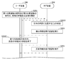
- the reader apparatus 10B transmits a request signal whose carrier wave has a first frequency (in other words, a first request signal) and a request signal whose carrier wave has a second frequency (in other words, a second request signal). Transmission, waiting for reception of a signal whose carrier wave has the first frequency (in other words, the first detection signal and the first response signal), and a signal whose carrier wave has the second frequency (in other words, Then, standby for reception of the second detection signal and the second response signal is started (step S201 in FIG. 9).
- the tag device 20B receives the first request signal and the second request signal. According to the above assumption, since the antenna 210 is in contact with air, the resonance frequency of the antenna 210 substantially matches the first frequency. Accordingly, the strength of the first request signal received by the antenna 210 is greater than the strength of the second request signal received by the antenna 210.
- the tag device 20B rectifies a current generated between the first antenna configuration unit 211 and the second antenna configuration unit 212 during at least a part of a period during which the first signal configuration unit of the request signal is received. Is stored in the capacitor by rectification.
- the tag device 20B demodulates the second signal component by using the electric power stored in the capacitor during at least a part of the period in which the second signal component of the request signal is received.
- the specific information is acquired based on the demodulated signal.
- the tag device 20B detects whether the tag device 20B is located inside the living body by using the sensor 223B. According to the above assumption, the tag device 20B detects that the tag device 20B is not located inside the living body (in other words, located outside the living body). (Step S2021 in FIG. 9).
- the tag device 20B uses the power stored in the capacitor in the first period component of the period in which the third signal component of the request signal is received.
- the request signal received by the antenna 210 is modulated, and the modulated request signal is transmitted as a detection signal (step S203 in FIG. 9).
- the tag device 20B transmits a detection signal representing detection information in accordance with the backscatter method.
- the detection signal transmitted by the antenna 210 includes a first detection signal (in other words, a first component) in which the carrier wave has the first frequency and a second detection in which the carrier wave has the second frequency.
- Signal in other words, the second component.
- the reader device 10B receives the detection signal transmitted by the tag device 20B.
- the reader device 10B acquires detection information based only on the higher one of the first detection signal and the second detection signal included in the received detection signal. Therefore, according to the above assumption, the reader device 10B acquires detection information based only on the first detection signal of the first detection signal and the second detection signal included in the received detection signal. .
- the reader device 10B based on the detection result represented by the acquired detection information, waits for reception and transmission of the signal having the first frequency on the carrier wave, and the signal having the second frequency on the carrier wave. One of reception standby and transmission is terminated. According to the above assumption, since the detection result indicates that the tag device 20B is located outside the living body, the reader device 10B transmits the second request signal, the second detection signal, and the second response. The reception of the signal is terminated (step S2041 in FIG. 9).
- the tag device 20B uses the electric power stored in the capacitor in the second period configuration unit of the period in which the third signal configuration unit of the request signal is received, based on the response information. Then, the request signal received by the antenna 210 is modulated, and the modulated request signal is transmitted as a response signal (step S205 in FIG. 9). In this way, in this example, the tag device 20B transmits a response signal representing the response information according to the backscatter method.
- the carrier wave of the response signal transmitted by the antenna 210 has the first frequency.
- the response signal does not include a component in which the carrier wave has the second frequency.
- the reader device 10B receives the response signal transmitted by the tag device 20B. According to the above assumption, the reader device 10B acquires response information based on the first response signal received by the first reception circuit 151.
- the tag device 20B is located inside the living body.
- the antenna 210 of the tag device 20B is in contact with a liquid inside the living body (in this example, saliva).
- the reader device 10B starts transmission of the first request signal and transmission of the second request signal, waits for reception of the first detection signal and the first response signal, and the second detection signal. And waiting for reception of the second response signal is started (step S201 in FIG. 10).
- the tag device 20B receives the first request signal and the second request signal. According to the above assumption, since the antenna 210 is in contact with the liquid inside the living body, the resonance frequency of the antenna 210 substantially matches the second frequency. Accordingly, the strength of the second request signal received by the antenna 210 is greater than the strength of the first request signal received by the antenna 210.
- the tag device 20B rectifies a current generated between the first antenna configuration unit 211 and the second antenna configuration unit 212 during at least a part of a period during which the first signal configuration unit of the request signal is received. Is stored in the capacitor by rectification.
- the tag device 20B demodulates the second signal component by using the electric power stored in the capacitor during at least a part of the period in which the second signal component of the request signal is received.
- the specific information is acquired based on the demodulated signal.
- the tag device 20B detects whether the tag device 20B is located inside the living body by using the sensor 223B. According to the above assumption, the tag device 20B detects that the tag device 20B is located inside the living body. (Step S2022 in FIG. 10).
- the tag device 20B uses the power stored in the capacitor in the first period component of the period in which the third signal component of the request signal is received.
- the request signal received by the antenna 210 is modulated, and the modulated request signal is transmitted as a detection signal (step S203 in FIG. 10).
- the tag device 20B transmits a detection signal representing detection information in accordance with the backscatter method.
- the detection signal transmitted by the antenna 210 includes a first detection signal (in other words, a first component) in which the carrier wave has the first frequency and a second detection in which the carrier wave has the second frequency.
- Signal in other words, the second component.
- the reader device 10B receives the detection signal transmitted by the tag device 20B.
- the reader device 10B acquires detection information based only on the higher one of the first detection signal and the second detection signal included in the received detection signal. Therefore, according to the above assumption, the reader device 10B acquires detection information based only on the second detection signal out of the first detection signal and the second detection signal included in the received detection signal. .
- the reader device 10B based on the detection result represented by the acquired detection information, waits for reception and transmission of the signal having the first frequency on the carrier wave, and the signal having the second frequency on the carrier wave. One of reception standby and transmission is terminated. According to the above assumption, since the detection result indicates that the tag device 20B is located inside the living body, the reader device 10B transmits the first request signal, the first detection signal, and the first response. The reception of the signal is terminated (step S2042 in FIG. 10).
- the tag device 20B uses the electric power stored in the capacitor in the second period configuration unit of the period in which the third signal configuration unit of the request signal is received, based on the response information. Then, the request signal received by the antenna 210 is modulated, and the modulated request signal is transmitted as a response signal (step S205 in FIG. 10). In this way, in this example, the tag device 20B transmits a response signal representing the response information according to the backscatter method.
- the carrier wave of the response signal transmitted by the antenna 210 has the second frequency.
- the response signal does not include a component in which the carrier wave has the first frequency.
- the reader device 10B receives the response signal transmitted by the tag device 20B. According to the above assumption, the reader device 10 ⁇ / b> B acquires response information based on the second response signal received by the second receiving circuit 152.
- the reader device 10B sets the frequency of the carrier wave of the signal transmitted by the reader device 10B when the tag device 20B is located outside the living body.
- the frequency of the carrier wave of the signal transmitted by the reader device 10B is controlled to the second frequency.
- the reader device 10B when the tag device 20B is located inside the living body, the reader device 10B can suppress the carrier wave from transmitting a signal having the first frequency. In addition, when the tag device 20B is located outside the living body, the reader device 10B can suppress the carrier wave from transmitting a signal having the second frequency. Therefore, for example, the amount of power consumed by the reader device 10B is suppressed as compared with the case where the reader device 10B transmits a signal having a carrier wave having a first frequency and a signal having a carrier wave having a second frequency. it can.
- reception standby and transmission of a signal having a first frequency on a carrier wave and reception standby and transmission of a signal having a second frequency on a carrier wave exceeds a predetermined threshold time.
- the reader apparatus 10B continues to receive and wait for reception of a signal whose carrier wave has the first frequency, and for reception and transmission of the signal whose carrier wave has the second frequency. The other may be resumed.
- the reader device 10B can communicate with the tag device 20B via the antenna 210 of the tag device 20B.
- the wireless communication system according to the second embodiment is different from the wireless communication system according to the first embodiment in that the tag device is an active type.
- the difference will be mainly described.
- symbol used in 1st Embodiment is the same or substantially the same.
- the reader device 10C of the second embodiment includes a control circuit 110C, a first reception antenna 141, a second reception antenna 142, a first reception circuit 151, and a second reception circuit.
- Receiving circuit 152 As illustrated in FIG. 11, the reader device 10C of the second embodiment includes a control circuit 110C, a first reception antenna 141, a second reception antenna 142, a first reception circuit 151, and a second reception circuit.
- Receiving circuit 152 As illustrated in FIG. 11, the reader device 10C of the second embodiment includes a control circuit 110C, a first reception antenna 141, a second reception antenna 142, a first reception circuit 151, and a second reception circuit.
- the first receiving circuit 151 and the second receiving circuit 152 correspond to a receiving unit.
- the control circuit 110C corresponds to a control unit.
- the first reception circuit 151 receives a notification signal (in other words, a first notification signal) in which the carrier wave has the first frequency via the first reception antenna 141.
- the notification signal represents notification information.
- the notification information includes at least one of information stored in the tag device 20C and information generated by the tag device 20C.
- the first frequency is included in a first frequency band among a plurality of frequency bands called an ISM band.
- the first frequency is included in the 5.8 GHz band (for example, 5.725 GHz to 5.875 GHz).
- the second reception circuit 152 receives a notification signal (in other words, a second notification signal) in which the carrier wave has the second frequency via the second reception antenna 142.
- the second frequency is lower than the first frequency.
- the second frequency is lower than half of the first frequency.
- the second frequency is included in a second frequency band lower than the first frequency band among a plurality of frequency bands called an ISM band.
- the second frequency is included in the 2.45 GHz band (for example, 2.4 GHz to 2.5 GHz).
- the control circuit 110C controls the first reception circuit 151 so that the first reception circuit 151 starts to wait for reception of the notification signal. Further, the control circuit 110C controls the first reception circuit 151 so that the first reception circuit 151 ends the reception of the notification signal.
- the control circuit 110 ⁇ / b> C controls the second reception circuit 152 in the same manner as the first reception circuit 151. In this example, the control circuit 110C causes the first receiving circuit 151 and the second receiving circuit 152 to simultaneously start standby for receiving the notification signal.
- control circuit 110C includes the first receiving circuit so that the standby for receiving the notification signal by the first receiving circuit 151 and the standby for receiving the notification signal by the second receiving circuit 152 are alternately performed. 151 and the second receiving circuit 152 may be controlled.
- control circuit 110C has the strength of the first notification signal received by the first reception circuit 151 and the second notification signal received by the second reception circuit 152. Broadcast information is acquired based only on the larger one.
- control circuit 110 ⁇ / b> C uses the tag based on the strength of the first notification signal received by the first reception circuit 151 and the strength of the second notification signal received by the second reception circuit 152. It may be detected that the device 20C has been introduced from outside the living body into the living body. In this case, the control circuit 110C changes from a state in which the strength of the first notification signal is greater than the strength of the second notification signal to a state in which the strength of the second notification signal is greater than the strength of the first notification signal. In this case, it may be detected that the tag device 20C has been introduced from the outside of the living body into the living body.
- control circuit 110 ⁇ / b> C uses the tag based on the strength of the first notification signal received by the first reception circuit 151 and the strength of the second notification signal received by the second reception circuit 152. It may be detected that the device 20C is discharged from the inside of the living body to the outside of the living body. In this case, the control circuit 110C changes from a state in which the strength of the second notification signal is greater than the strength of the first notification signal to a state in which the strength of the first notification signal is greater than the strength of the second notification signal. In this case, it may be detected that the tag device 20C is discharged from the inside of the living body to the outside of the living body.
- the tag device 20C of the second embodiment includes an antenna 210 and an IC unit 220C.
- the IC unit 220C corresponds to a transmission unit.
- the antenna 210 is configured similarly to the antenna 210 of the first embodiment.
- the IC unit 220C is connected to the first antenna configuration unit 211 and the second antenna configuration unit 212.
- the IC unit 220C includes a first transmission circuit 224C, a second transmission circuit 225C, and a battery 226C.
- the tag device 20C is an active type.
- the first transmission circuit 224C uses the electric power stored in the battery 226C to transmit a notification signal (in other words, the first notification signal) having a carrier wave having the first frequency via the antenna 210.
- the first transmission circuit 224C transmits a first notification signal modulated according to a predetermined first modulation scheme.
- the first modulation method is an AM method, an FM method, or a PM method.
- the first modulation method may be a combination of at least two of the AM method, the FM method, and the PM method.
- the second transmission circuit 225C uses the power stored in the battery 226C to transmit a notification signal (in other words, a second notification signal) having a carrier wave having the second frequency via the antenna 210.
- the second transmission circuit 225C transmits a second notification signal modulated according to a predetermined second modulation scheme.
- the second modulation method is an AM method, an FM method, or a PM method.
- the second modulation method may be a combination of at least two of the AM method, the FM method, and the PM method.
- the notification information includes information stored in advance by the IC unit 220C.
- the notification information may include an identifier that identifies the tag device 20C.
- the tag device 20C includes a sensor that detects a physical quantity
- the notification information is replaced with information stored in advance in the IC unit 220C or in addition to information stored in advance in the IC unit 220C.
- Information representing a physical quantity detected by the sensor may be included.
- the physical quantity is temperature, humidity, illuminance, pH, acceleration, angular velocity, pressure, or the concentration of an object.
- the object is digestive fluid (for example, saliva, gastric fluid, intestinal fluid, or pancreatic fluid), blood, resident bacteria, or infectious substance (for example, bacteria or virus).
- the tag device 20C includes a first battery connected to the first transmission circuit 224C and a second battery connected to the second transmission circuit 225C instead of or in addition to the battery 226C. And a battery.
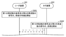
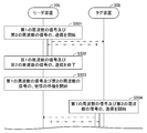
- the reader device 10C waits for reception of a notification signal (in other words, first notification signal) in which the carrier wave has the first frequency, and a notification signal (in other words, second notification signal in which the carrier wave has the second frequency). ) Is started (step S301 in FIG. 13).
- a notification signal in other words, first notification signal
- a notification signal in other words, second notification signal in which the carrier wave has the second frequency
- the tag device 20C starts transmission of the first notification signal and transmission of the second notification signal (step S302 in FIG. 13).
- the broadcast signal transmitted by the antenna 210 includes a first broadcast signal (in other words, a first component) in which a carrier wave has a first frequency and a second broadcast signal (in other words, a carrier wave having a second frequency). , Second component).
- a first broadcast signal in other words, a first component
- a second broadcast signal in other words, a carrier wave having a second frequency.
- Second component Second component
- the reader device 10C receives the notification signal transmitted by the tag device 20C.
- the reader device 10C acquires notification information based only on the higher one of the first notification signal and the second notification signal included in the received notification signal. Therefore, according to the above assumption, the reader device 10C acquires notification information based only on the first notification signal of the first notification signal and the second notification signal included in the received notification signal. .
- the tag device 20C is located inside the living body.
- the antenna 210 of the tag device 20C is in contact with the liquid inside the living body (in this example, saliva).
- the reader device 10C starts waiting for reception of the first notification signal and waiting for reception of the second notification signal.
- the tag device 20C starts transmission of the first notification signal and transmission of the second notification signal.
- the broadcast signal transmitted by the antenna 210 includes a first broadcast signal (in other words, a first component) in which a carrier wave has a first frequency and a second broadcast signal (in other words, a carrier wave having a second frequency). , Second component).
- a first broadcast signal in other words, a first component
- a second broadcast signal in other words, a carrier wave having a second frequency.
- Second component Second component
- the reader device 10C receives the notification signal transmitted by the tag device 20C.
- the reader device 10C acquires notification information based only on the higher one of the first notification signal and the second notification signal included in the received notification signal. Therefore, according to the above assumption, the reader device 10C acquires notification information based only on the second notification signal of the first notification signal and the second notification signal included in the received notification signal. .
- the wireless communication system 1 when the tag device 20C is located outside the living body, the communication between the tag device 20C and the reader device 10C via the antenna 210 is performed. A frequency of 1 is used. Furthermore, when the tag device 20C is located inside the living body, the wireless communication system 1 uses a second frequency lower than the first frequency for communication via the antenna 210 between the tag device 20C and the reader device 10C. Is used.
- the reader device 10C can communicate with the tag device 20C via the antenna 210 of the tag device 20C.
- the reader device 10C of the second embodiment receives a signal having the first frequency and a signal having the second frequency.
- the reader device 10C can receive a signal having the first frequency. Further, when the tag device 20C is located inside the living body, the reader device 10C can receive a signal having the second frequency. Accordingly, the reader device 10C can communicate with the tag device 20C via the antenna 210 of the tag device 20C regardless of whether the tag device 20C is located inside or outside the living body.
- the tag device 20C of the second embodiment transmits a signal having the first frequency via the antenna 210 and transmits a signal having the second frequency via the antenna 210.
- the reader device 10C can receive a signal having the first frequency. Further, when the tag device 20C is located inside the living body, the reader device 10C can receive a signal having the second frequency. Accordingly, the reader device 10C can communicate with the tag device 20C via the antenna 210 of the tag device 20C regardless of whether the tag device 20C is located inside or outside the living body.
- the wireless communication system 1 uses a frequency included in a 2.45 GHz band (for example, 2.4 GHz to 2.5 GHz) as the first frequency, and a 900 MHz band (for example, 915 MHz to 915 MHz) as the second frequency. 955 MHz) may be used.
- a 2.45 GHz band for example, 2.4 GHz to 2.5 GHz
- a 900 MHz band for example, 915 MHz to 915 MHz
- 955 MHz may be used.
- the wireless communication system 1 uses a frequency included in the 5.8 GHz band (for example, 5.725 GHz to 5.875 GHz) as the first frequency, and the 900 MHz band (for example, 915 MHz to 915 MHz) as the second frequency. 955 MHz) may be used.
- 5.8 GHz band for example, 5.725 GHz to 5.875 GHz
- 900 MHz band for example, 915 MHz to 915 MHz
- 955 MHz may be used.
- the wireless communication system 1 uses a frequency included in a 60 GHz band (for example, 57 GHz to 66 GHz) as the first frequency, and a 5.8 GHz band (for example, 5.725 GHz to 5.725) as the second frequency. 875 GHz) may be used.
- a frequency included in a 60 GHz band for example, 57 GHz to 66 GHz
- a 5.8 GHz band for example, 5.725 GHz to 5.725
- 875 GHz 875 GHz
- the wireless communication system 1 uses a frequency included in a 24 GHz band (for example, 24 GHz to 24.25 GHz) as the first frequency, and a 5.8 GHz band (for example, 5.725 GHz to The frequency included in 5.875 GHz may be used.
- a 24 GHz band for example, 24 GHz to 24.25 GHz
- a 5.8 GHz band for example, 5.725 GHz to The frequency included in 5.875 GHz may be used.
- the tag device 20C may include a changing unit that changes the resonance frequency of the antenna 210.
- the changing unit may include a first extension antenna configuration unit, a second extension antenna configuration unit, a first switching element, and a second switching element.
- the first extension antenna component is connected to the first antenna component 211 via the first switching element.
- the first switching element cuts off the state in which the first antenna component 211 and the first extension antenna component are connected, and the first antenna component 211 and the first extension antenna component.
- the state of the first switching element is switched to the state.
- the second extension antenna component is connected to the second antenna component 212 via the second switching element.
- the second switching element cuts off the state in which the second antenna component 212 and the second extension antenna component are connected, and the second antenna component 212 and the second extension antenna component.
- the state of the second switching element is switched to the state.
- the ratio between the first frequency and the second frequency can be changed to a ratio different from the value corresponding to the ratio between the dielectric constant of the air and the dielectric constant of the liquid inside the living body. Therefore, the freedom degree of the frequency used for communication between the reader device 10C and the tag device 20C can be increased.
- the reader device 10C receives the notification signal, and the first notification signal included in the notification signal has a strength lower than that of the second notification signal included in the notification signal. The reception of the notification signal may be terminated. In addition, the reader device 10C receives the notification signal, and the second notification signal included in the notification signal is smaller in intensity than the first notification signal included in the notification signal. The reception of the notification signal may be terminated.
- the reader device 10C it is possible to suppress the amount of power consumed to wait for reception of the notification signal.
- the tag device 20C receives the first frequency signal and the second frequency signal. Transmission of a signal having a frequency of 2 may be started.
- wireless communications system of the 1st modification of 2nd Embodiment detects whether the tag apparatus is located inside a biological body with respect to the radio
- the difference will be mainly described.
- symbol used in 2nd Embodiment is the same or substantially the same.
- the tag device 20D of the first modification example of the second embodiment includes an IC unit 220D instead of the IC unit 220C of the tag device 20C of the second embodiment.
- the IC unit 220D includes a first transmission circuit 224D, a second transmission circuit 225D, a battery 226D, a switching element 227D, and a sensor 228D.
- the sensor 228D corresponds to a detection unit.
- the IC unit 220D corresponds to a transmission unit.
- the sensor 228D detects whether or not the tag device 20D is located inside the living body.
- the sensor 228D detects the temperature, and detects that the tag device 20D is located inside the living body when the detected temperature is equal to or higher than a predetermined threshold (for example, 307K), When the detected temperature is lower than the threshold, it is detected that the tag device 20D is located outside the living body.
- a predetermined threshold for example, 307K
- the sensor 228D may detect whether or not the tag device 20D is located inside the living body based on a physical quantity different from the temperature in addition to the temperature or instead of the temperature.
- the physical quantity is illuminance, pH, or the concentration of a body object.
- the body object is digestive fluid (eg, saliva, gastric fluid, intestinal fluid, pancreatic juice, etc.), blood, or resident bacteria.
- the sensor 228D operates by using the electric power stored in the battery 226D.
- Switching element 227D switches the state of switching element 227D between the first connection state and the second connection state based on the detection result by sensor 228D.
- the switching element 227D connects the first transmission circuit 224D and the battery 226D, and the switching element 227D blocks the second transmission circuit 225D and the battery 226D (in other words, does not connect).
- the second connection state is a state in which the switching element 227D blocks the first transmission circuit 224D and the battery 226D, and the switching element 227D connects the second transmission circuit 225D and the battery 226D.
- the switching element 227D switches the state of the switching element 227D to the first connection state. Furthermore, when the detection result by the sensor 228D indicates that the tag device 20D is located inside the living body, the switching element 227D switches the state of the switching element 227D to the second connection state. In this example, the switching element 227D operates by using the electric power stored in the battery 226D.
- the first transmission circuit 224D uses the power stored in the battery 226D, so that the notification signal (in other words, the carrier wave has the first frequency) A first notification signal) is transmitted via the antenna 210.
- the first transmission circuit 224D transmits a first notification signal modulated according to a predetermined first modulation scheme.
- the first modulation method is an AM method, an FM method, or a PM method.
- the first modulation method may be a combination of at least two of the AM method, the FM method, and the PM method.
- the second transmission circuit 225D uses the power stored in the battery 226D, so that the notification signal (in other words, the carrier wave has the second frequency) A second notification signal) is transmitted via the antenna 210.
- the second transmission circuit 225D transmits a second notification signal modulated according to a predetermined second modulation scheme.
- the second modulation method is an AM method, an FM method, or a PM method.
- the second modulation method may be a combination of at least two of the AM method, the FM method, and the PM method.
- the reader device 10C waits for reception of a notification signal (in other words, the first notification signal) in which the carrier wave has the first frequency and a notification signal (in other words, the second notification signal in which the carrier wave has the second frequency). ) Is started (step S401 in FIG. 15).
- the tag device 20D detects whether the tag device 20D is located inside the living body by using the sensor 228D. According to the above assumption, the tag device 20D detects that the tag device 20D is not located inside the living body (in other words, located outside the living body). (Step S4021 in FIG. 15).
- the switching element 227D switches the state of the switching element 227D to the first connection state.
- tag device 20D starts transmission of the 1st information signal (Step S4031 of Drawing 15).
- the carrier wave of the broadcast signal transmitted by the antenna 210 has the first frequency.
- the broadcast signal does not include a component in which the carrier wave has the second frequency.
- the reader device 10C receives the notification signal transmitted by the tag device 20D. According to the above assumption, the reader device 10C acquires notification information based on the first notification signal received by the first reception circuit 151.
- the tag device 20D is located inside the living body.
- the antenna 210 of the tag device 20D is in contact with the liquid inside the living body (in this example, saliva).
- the reader device 10C starts waiting for reception of the first notification signal and waiting for reception of the second notification signal (step S401 in FIG. 16).
- the tag device 20D detects whether the tag device 20D is located inside the living body by using the sensor 228D. According to the above assumption, the tag device 20D detects that the tag device 20D is located inside the living body. (Step S4022 in FIG. 16).
- the switching element 227D switches the state of the switching element 227D to the second connection state.
- tag device 20D starts transmission of the 2nd information signal (Step S4032 of Drawing 16).
- the carrier wave of the notification signal transmitted by the antenna 210 has the second frequency.
- the broadcast signal does not include a component in which the carrier wave has the first frequency.
- the reader device 10C receives the notification signal transmitted by the tag device 20D. According to the above assumption, the reader device 10 ⁇ / b> C acquires notification information based on the second notification signal received by the second reception circuit 152.
- the tag device 20D has a carrier wave of a signal transmitted by the tag device 20D when it is detected that the tag device 20D is located outside the living body.
- the frequency is controlled to the first frequency.
- the frequency of the carrier wave of the signal transmitted by the tag device 20D is controlled to the second frequency.
- the tag device 20D when the tag device 20D is located inside the living body, it is possible to suppress the tag device 20D from transmitting a signal having the first frequency. Further, when the tag device 20D is located outside the living body, it is possible to suppress the tag device 20D from transmitting a signal having the second frequency. Therefore, for example, the amount of power consumed by the tag device 20D can be suppressed as compared with the case where the tag device 20D transmits each of the signal having the first frequency and the signal having the second frequency.
- the tag device 20D When only one of the transmission of the signal having the first frequency as the carrier wave and the transmission of the signal having the second frequency as the carrier wave continues for a predetermined threshold time or more, the tag device 20D The detection of whether or not the tag device 20D is located inside the living body and the control of the frequency based on the detection result may be executed again.
- the reader device 10C can communicate with the tag device 20D via the antenna 210 of the tag device 20D. .
- the wireless communication system 1 determines whether or not the tag device 20D is located inside the living body before the reader device 10C starts waiting for reception of the first frequency signal and the second frequency signal. And the transmission of the signal of the first frequency or the signal of the second frequency may be started.
- the wireless communication system according to the third embodiment is different from the wireless communication system according to the first embodiment in that the tag device is a semi-active type.
- the difference will be mainly described.
- symbol used in 1st Embodiment is the same or substantially the same.
- the reader device 10E of the third embodiment includes a control circuit 110E, a first transmission circuit 121, a second transmission circuit 122, a first transmission antenna 131, and a second transmission circuit.
- the first transmission circuit 121 and the second transmission circuit 122 correspond to a transmission unit.
- the first receiving circuit 151 and the second receiving circuit 152 correspond to a receiving unit.
- the control circuit 110E corresponds to a control unit.
- the first transmission circuit 121 transmits a request signal whose carrier wave has the first frequency (in other words, the first request signal) via the first transmission antenna 131.
- the first frequency is included in a first frequency band among a plurality of frequency bands called an ISM band.
- the first frequency is included in the 5.8 GHz band (for example, 5.725 GHz to 5.875 GHz).
- the request signal is a signal that requests the tag device 20E described later to transmit information.
- the request signal includes a first signal configuration unit and a second signal configuration unit that are continuous in the time axis.
- the first signal component is an unmodulated wave (in other words, a carrier wave).
- the second signal component is a modulated wave (in other words, a radio wave in which a carrier wave is modulated).
- the second signal component represents specific information.
- the specific information specifies information that requests the tag device 20E to transmit.
- the first signal configuration unit and the second signal configuration unit each have a first time length and a second time length that are determined in advance.
- the second transmission circuit 122 transmits a request signal whose carrier wave has the second frequency (in other words, the second request signal) via the second transmission antenna 132.
- the second frequency is lower than the first frequency.
- the second frequency is lower than half of the first frequency.
- the second frequency is included in a second frequency band lower than the first frequency band among a plurality of frequency bands called an ISM band.
- the second frequency is included in the 2.45 GHz band (for example, 2.4 GHz to 2.5 GHz).
- the first receiving circuit 151 receives a response signal (in other words, a first response signal) having a carrier wave having a first frequency via the first receiving antenna 141.
- the response signal represents response information.
- the response information includes at least one of information stored in the tag device 20E and information generated by the tag device 20E.
- the second receiving circuit 152 receives a response signal (in other words, a second response signal) in which the carrier wave has the second frequency via the second receiving antenna 142.
- the control circuit 110E controls the first transmission circuit 121 so that the first transmission circuit 121 starts transmission of the request signal. Further, the control circuit 110E controls the first transmission circuit 121 so that the first transmission circuit 121 ends the transmission of the request signal. The control circuit 110E controls the second transmission circuit 122 in the same manner as the first transmission circuit 121.
- the control circuit 110E controls the first reception circuit 151 so that the first reception circuit 151 starts to wait for reception of the response signal. Further, the control circuit 110E controls the first reception circuit 151 so that the first reception circuit 151 ends the waiting for reception of the response signal. The control circuit 110E controls the second reception circuit 152 in the same manner as the first reception circuit 151.
- control circuit 110E causes the first transmission circuit 121 and the second transmission circuit 122 to simultaneously start transmitting request signals. Thereafter, the control circuit 110E causes the first transmission circuit 121 and the second transmission circuit 122 to finish transmitting the request signal at the same time. Thereafter, the control circuit 110E causes the first receiving circuit 151 and the second receiving circuit 152 to simultaneously start waiting for reception of the response signal. Note that the control circuit 110E may control the first reception circuit 151 and the second reception circuit 152 so that standby for reception of the response signal starts almost simultaneously with the end of transmission of the request signal.
- control circuit 110E includes the first transmission circuit 121 and the second transmission circuit 121 so that the transmission of the request signal by the first transmission circuit 121 and the transmission of the request signal by the second transmission circuit 122 are alternately performed.
- the transmission circuit 122 may be controlled.
- control circuit 110E includes a first receiving circuit so that the standby for receiving the response signal by the first receiving circuit 151 and the standby for receiving the response signal by the second receiving circuit 152 are alternately performed. 151 and the second receiving circuit 152 may be controlled.
- control circuit 110E has the strength of the first response signal received by the first reception circuit 151 and the second response signal received by the second reception circuit 152. Get response information based only on the larger one.
- control circuit 110E uses the tag based on the strength of the first response signal received by the first receiving circuit 151 and the strength of the second response signal received by the second receiving circuit 152. It may be detected that the device 20E is introduced from the outside of the living body to the inside of the living body. In this case, the control circuit 110E changes the state where the strength of the first response signal is greater than the strength of the second response signal to the state where the strength of the second response signal is greater than the strength of the first response signal. In this case, it may be detected that the tag device 20E has been introduced from the outside of the living body into the living body.
- control circuit 110E generates a tag based on the strength of the first response signal received by the first receiving circuit 151 and the strength of the second response signal received by the second receiving circuit 152. It may be detected that the device 20E is discharged from the inside of the living body to the outside of the living body. In this case, the control circuit 110E changes the state where the strength of the second response signal is greater than the strength of the first response signal to a state where the strength of the first response signal is greater than the strength of the second response signal. In this case, it may be detected that the tag device 20E is discharged from the inside of the living body to the outside of the living body.
- the tag device 20E As shown in FIG. 18, the tag device 20E according to the third embodiment includes an antenna 210 and an IC unit 220E.
- the IC unit 220E corresponds to a transmission unit.
- the antenna 210 is configured similarly to the antenna 210 of the first embodiment.
- the IC unit 220E is connected to the first antenna configuration unit 211 and the second antenna configuration unit 212.
- the IC unit 220E includes a first transmission circuit 224E, a second transmission circuit 225E, and a battery 226E.
- the tag device 20E is a semi-active type.
- the IC unit 220E includes a rectifier and a capacitor (not shown), and at least part of a period during which the first signal component of the request signal is received, The current generated between the two antenna components 212 is rectified by a rectifier and stored in a capacitor.
- the IC unit 220E demodulates the second signal component by using the electric power stored in the capacitor in at least a part of the period during which the second signal component of the request signal is received. .
- the IC unit 220E acquires specific information based on the demodulated signal.
- the IC unit 220E uses the power stored in the battery 226E during at least a part of the period during which the second signal component of the request signal is received without using a rectifier and a capacitor (not shown).
- the second signal component may be demodulated.
- the request signal may not include the first signal component.
- the first transmission circuit 224E uses the power stored in the battery 226E to transmit a response signal (in other words, the first response signal) in which the carrier wave has the first frequency via the antenna 210.
- the first transmission circuit 224E transmits a first response signal modulated according to a predetermined first modulation scheme.
- the first modulation method is an AM method, an FM method, or a PM method.
- the first modulation method may be a combination of at least two of the AM method, the FM method, and the PM method.
- the second transmission circuit 225E uses the electric power stored in the battery 226E to transmit a response signal whose carrier wave has the second frequency (in other words, the second response signal) via the antenna 210.
- the second transmission circuit 225E transmits a second response signal modulated according to a predetermined second modulation scheme.
- the second modulation method is an AM method, an FM method, or a PM method.
- the second modulation method may be a combination of at least two of the AM method, the FM method, and the PM method.
- the response information includes information stored in advance by the IC unit 220E.
- the response information may include an identifier that identifies the tag device 20E.
- the tag device 20E includes a sensor that detects a physical quantity
- the response information is replaced with information stored in advance by the IC unit 220E or in addition to information stored in advance by the IC unit 220E.
- Information representing a physical quantity detected by the sensor may be included.
- the physical quantity is temperature, humidity, illuminance, pH, acceleration, angular velocity, pressure, or the concentration of an object.
- the object is digestive fluid (for example, saliva, gastric fluid, intestinal fluid, or pancreatic fluid), blood, resident bacteria, or infectious substance (for example, bacteria or virus).
- the tag device 20E includes a first battery connected to the first transmission circuit 224E and a second battery connected to the second transmission circuit 225E instead of or in addition to the battery 226E. And a battery.
- the reader apparatus 10E transmits a request signal whose carrier wave has the first frequency (in other words, the first request signal) and a request signal whose carrier wave has the second frequency (in other words, the second request signal). Transmission is started (step S501 in FIG. 19).
- the tag device 20E receives the first request signal and the second request signal. According to the above assumption, since the antenna 210 is in contact with air, the resonance frequency of the antenna 210 substantially matches the first frequency. Accordingly, the strength of the first request signal received by the antenna 210 is greater than the strength of the second request signal received by the antenna 210.
- the tag device 20E rectifies a current generated between the first antenna configuration unit 211 and the second antenna configuration unit 212 in at least a part of a period during which the first signal configuration unit of the request signal is received. Is stored in the capacitor by rectification.
- the tag device 20E demodulates the second signal component by using the electric power stored in the capacitor during at least part of the period during which the second signal component of the request signal is received.
- the specific information is acquired based on the demodulated signal.
- the reader device 10E ends the transmission of the first request signal and the transmission of the second request signal (step S502 in FIG. 19). Then, the reader device 10E waits for reception of a response signal whose carrier wave has the first frequency (in other words, the first response signal) and response signal whose carrier wave has the second frequency (in other words, the second response signal). The reception of the response signal is started (step S503 in FIG. 19).
- the tag device 20E starts transmission of the first response signal and transmission of the second response signal (step S504 in FIG. 19).
- the response signal transmitted by the antenna 210 includes a first response signal whose carrier wave has a first frequency (in other words, a first component) and a second response signal whose carrier wave has a second frequency (second signal). Component).
- first response signal whose carrier wave has a first frequency
- second response signal whose carrier wave has a second frequency (second signal). Component).
- the reader device 10E receives the response signal transmitted by the tag device 20E.
- the reader device 10E acquires response information based only on the higher one of the first response signal and the second response signal included in the received response signal. Therefore, according to the above assumption, the reader device 10E acquires response information based only on the first response signal out of the first response signal and the second response signal included in the received response signal. .
- the tag device 20E is located inside the living body.
- the antenna 210 of the tag device 20E is in contact with a liquid inside the living body (in this example, saliva).
- the reader device 10E starts transmission of the first request signal and transmission of the second request signal.
- the tag device 20E receives the first request signal and the second request signal. According to the above assumption, since the antenna 210 is in contact with the liquid inside the living body, the resonance frequency of the antenna 210 substantially matches the second frequency. Accordingly, the strength of the second request signal received by the antenna 210 is greater than the strength of the first request signal received by the antenna 210.
- the tag device 20E rectifies a current generated between the first antenna configuration unit 211 and the second antenna configuration unit 212 in at least a part of a period during which the first signal configuration unit of the request signal is received. Is stored in the capacitor by rectification.
- the tag device 20E demodulates the second signal component by using the electric power stored in the capacitor during at least part of the period during which the second signal component of the request signal is received.
- the specific information is acquired based on the demodulated signal.
- the reader device 10E ends the transmission of the first request signal and the transmission of the second request signal. Then, the reader device 10E starts waiting for reception of the first response signal and waiting for reception of the second response signal. Further, the tag device 20E starts transmission of the first response signal and transmission of the second response signal.
- the response signal transmitted by the antenna 210 includes a first response signal whose carrier wave has a first frequency (in other words, a first component) and a second response signal whose carrier wave has a second frequency (in other words, a first component). , Second component).
- a first response signal whose carrier wave has a first frequency
- a second response signal whose carrier wave has a second frequency (in other words, a first component).
- Second component Second component
- the reader device 10E receives the response signal transmitted by the tag device 20E.
- the reader device 10E acquires response information based only on the higher one of the first response signal and the second response signal included in the received response signal. Therefore, according to the above assumption, the reader device 10E obtains response information based only on the second response signal out of the first response signal and the second response signal included in the received response signal. .
- the wireless communication system 1 when the tag device 20E is located outside the living body, the communication between the tag device 20E and the reader device 10E via the antenna 210 is performed. A frequency of 1 is used. Furthermore, when the tag device 20E is located inside the living body, the wireless communication system 1 uses a second frequency lower than the first frequency for communication between the tag device 20E and the reader device 10E via the antenna 210. Is used.
- the reader device 10E can communicate with the tag device 20E via the antenna 210 of the tag device 20E.
- the reader device 10E of the third embodiment receives a signal having the first frequency and a signal having the second frequency.
- the reader device 10E can receive a signal having the first frequency.
- the reader device 10E can receive a signal having the second frequency. Accordingly, the reader device 10E can communicate with the tag device 20E via the antenna 210 of the tag device 20E regardless of whether the tag device 20E is located inside or outside the living body.
- the tag device 20E of the third embodiment transmits a signal having the first frequency via the antenna 210 and transmits a signal having the second frequency via the antenna 210.
- the reader device 10E can receive a signal having the first frequency.
- the reader device 10E can receive a signal having the second frequency. Accordingly, the reader device 10E can communicate with the tag device 20E via the antenna 210 of the tag device 20E regardless of whether the tag device 20E is located inside or outside the living body.
- the reader device 10E of the third embodiment transmits a signal having the first frequency and a signal having the second frequency.
- the tag device 20E when the tag device 20E is located outside the living body, the tag device 20E can receive a signal having the first frequency. Further, when the tag device 20E is located inside the living body, the tag device 20E can receive a signal having the second frequency. Therefore, regardless of whether the tag device 20E is located inside or outside the living body, the tag device 20E can communicate with the reader device 10E via the antenna 210 included in the tag device 20E.
- the wireless communication system 1 uses a frequency included in a 2.45 GHz band (for example, 2.4 GHz to 2.5 GHz) as the first frequency, and a 900 MHz band (for example, 915 MHz to 915 MHz) as the second frequency. 955 MHz) may be used.
- a 2.45 GHz band for example, 2.4 GHz to 2.5 GHz
- a 900 MHz band for example, 915 MHz to 915 MHz
- 955 MHz may be used.
- the wireless communication system 1 uses a frequency included in the 5.8 GHz band (for example, 5.725 GHz to 5.875 GHz) as the first frequency, and the 900 MHz band (for example, 915 MHz to 915 MHz) as the second frequency. 955 MHz) may be used.
- 5.8 GHz band for example, 5.725 GHz to 5.875 GHz
- 900 MHz band for example, 915 MHz to 915 MHz
- 955 MHz may be used.
- the wireless communication system 1 uses a frequency included in a 60 GHz band (for example, 57 GHz to 66 GHz) as the first frequency, and a 5.8 GHz band (for example, 5.725 GHz to 5.725) as the second frequency. 875 GHz) may be used.
- a frequency included in a 60 GHz band for example, 57 GHz to 66 GHz
- a 5.8 GHz band for example, 5.725 GHz to 5.725
- 875 GHz 875 GHz
- the wireless communication system 1 uses a frequency included in a 24 GHz band (for example, 24 GHz to 24.25 GHz) as the first frequency, and a 5.8 GHz band (for example, 5.725 GHz to The frequency included in 5.875 GHz may be used.
- a 24 GHz band for example, 24 GHz to 24.25 GHz
- a 5.8 GHz band for example, 5.725 GHz to The frequency included in 5.875 GHz may be used.
- the tag device 20E may include a changing unit that changes the resonance frequency of the antenna 210.
- the changing unit may include a first extension antenna configuration unit, a second extension antenna configuration unit, a first switching element, and a second switching element.
- the first extension antenna component is connected to the first antenna component 211 via the first switching element.
- the first switching element cuts off the state in which the first antenna component 211 and the first extension antenna component are connected, and the first antenna component 211 and the first extension antenna component.
- the state of the first switching element is switched to the state.
- the second extension antenna component is connected to the second antenna component 212 via the second switching element.
- the second switching element cuts off the state in which the second antenna component 212 and the second extension antenna component are connected, and the second antenna component 212 and the second extension antenna component.
- the state of the second switching element is switched to the state.
- the ratio between the first frequency and the second frequency can be changed to a ratio different from the value corresponding to the ratio between the dielectric constant of the air and the dielectric constant of the liquid inside the living body. Therefore, the freedom degree of the frequency used for communication between the reader apparatus 10E and the tag apparatus 20E can be improved.
- the reader device 10E receives the response signal, and the first response signal included in the response signal has a strength lower than that of the second response signal included in the response signal. The reception of the response signal may be terminated. In addition, when the reader device 10E receives the response signal and the strength of the second response signal included in the response signal is smaller than the strength of the first response signal included in the response signal, the second response device 10E The reception of the response signal may be terminated.
- the tag device 20E receives the first frequency signal and the first frequency signal. Transmission of a signal having a frequency of 2 may be started.
- wireless communications system of the 1st modification of 3rd Embodiment is demonstrated.
- the wireless communication system of the first modified example of the third embodiment detects whether the tag device is located inside the living body with respect to the wireless communication system of the third embodiment, and based on the detection result, The difference is that the frequency used for communication is controlled.
- the difference will be mainly described.
- symbol used in 3rd Embodiment is the same or substantially the same.
- a tag device 20F according to a first modification of the third embodiment includes an IC unit 220F instead of the IC unit 220E of the tag device 20E according to the third embodiment.
- the IC unit 220F includes a first transmission circuit 224F, a second transmission circuit 225F, a battery 226F, a switching element 227F, and a sensor 228F.
- the sensor 228F corresponds to a detection unit.
- the IC unit 220F corresponds to a transmission unit.
- the IC unit 220F includes a rectifier and a capacitor (not shown), and at least part of a period during which the first signal component of the request signal is received, the first antenna component 211 and the first antenna The current generated between the two antenna components 212 is rectified by a rectifier and stored in a capacitor.
- the IC unit 220F demodulates the second signal component by using the electric power stored in the capacitor during at least a part of the period in which the second signal component of the request signal is received. .
- the IC unit 220F acquires specific information based on the demodulated signal.
- the IC unit 220F uses the power stored in the battery 226F in at least a part of the period during which the second signal component of the request signal is received without using a rectifier and a capacitor (not shown).
- the second signal component may be demodulated.
- the request signal may not include the first signal component.
- Sensor 228F detects whether or not tag device 20F is located inside the living body.
- the sensor 228F detects the temperature, and detects that the tag device 20F is located inside the living body when the detected temperature is equal to or higher than a predetermined threshold (for example, 307K), When the detected temperature is lower than the threshold value, it is detected that the tag device 20F is located outside the living body.
- a predetermined threshold for example, 307K
- the sensor 228F may detect whether or not the tag device 20F is located inside the living body based on a physical quantity different from the temperature in addition to the temperature or instead of the temperature.
- the physical quantity is illuminance, pH, or the concentration of a body object.
- the body object is digestive fluid (eg, saliva, gastric fluid, intestinal fluid, pancreatic juice, etc.), blood, or resident bacteria.
- the sensor 228F operates by using the electric power stored in the capacitor. Note that the sensor 228F may operate by using electric power stored in the battery 226F.
- Switching element 227F switches the state of switching element 227F between the first connection state and the second connection state based on the detection result by sensor 228F.
- the switching element 227F connects the first transmission circuit 224F and the battery 226F, and the switching element 227F blocks the second transmission circuit 225F and the battery 226F (in other words, does not connect).
- the second connection state is a state in which the switching element 227F blocks the first transmission circuit 224F and the battery 226F, and the switching element 227F connects the second transmission circuit 225F and the battery 226F.
- the switching element 227F switches the state of the switching element 227F to the first connection state. Furthermore, when the detection result by the sensor 228F indicates that the tag device 20F is located inside the living body, the switching element 227F switches the state of the switching element 227F to the second connection state. In this example, the switching element 227F operates by using the electric power stored in the capacitor. Note that the switching element 227F may operate by using electric power stored in the battery 226F.
- the first transmission circuit 224F uses the power stored in the battery 226F, so that the carrier wave has a response signal having the first frequency (in other words, A first response signal) is transmitted via the antenna 210.
- the first transmission circuit 224F transmits a first response signal modulated according to a predetermined first modulation scheme.
- the first modulation method is an AM method, an FM method, or a PM method.
- the first modulation method may be a combination of at least two of the AM method, the FM method, and the PM method.
- the second transmission circuit 225F uses the power stored in the battery 226F, so that the carrier wave has a response signal having the second frequency (in other words, A second response signal) is transmitted via the antenna 210.
- the second transmission circuit 225F transmits the second response signal modulated in accordance with a predetermined second modulation scheme.
- the second modulation method is an AM method, an FM method, or a PM method.
- the second modulation method may be a combination of at least two of the AM method, the FM method, and the PM method.
- the reader apparatus 10E transmits a request signal whose carrier wave has the first frequency (in other words, the first request signal) and a request signal whose carrier wave has the second frequency (in other words, the second request signal). Transmission is started (step S601 in FIG. 21).
- the tag device 20F receives the first request signal and the second request signal. According to the above assumption, since the antenna 210 is in contact with air, the resonance frequency of the antenna 210 substantially matches the first frequency. Accordingly, the strength of the first request signal received by the antenna 210 is greater than the strength of the second request signal received by the antenna 210.
- the tag device 20F rectifies the current generated between the first antenna configuration unit 211 and the second antenna configuration unit 212 during at least a part of the period during which the first signal configuration unit of the request signal is received. Is stored in the capacitor by rectification.
- the tag device 20F demodulates the second signal component by using the electric power stored in the capacitor during at least a part of the period during which the second signal component of the request signal is received.
- the specific information is acquired based on the demodulated signal.
- the reader device 10E ends the transmission of the first request signal and the transmission of the second request signal (step S602 in FIG. 21). Then, the reader device 10E waits for reception of a response signal whose carrier wave has the first frequency (in other words, the first response signal) and response signal whose carrier wave has the second frequency (in other words, the second response signal). The reception of the response signal is started (step S603 in FIG. 21).
- the tag device 20F uses the sensor 228F to detect whether the tag device 20F is located inside the living body. According to the above assumption, the tag device 20F detects that the tag device 20F is not located inside the living body (in other words, located outside the living body). (Step S6041 in FIG. 21).
- the switching element 227F switches the state of the switching element 227F to the first connection state.
- the tag device 20F starts transmission of the first response signal (step S6051 in FIG. 21).
- the carrier wave of the response signal transmitted by the antenna 210 has the first frequency.
- the response signal does not include a component in which the carrier wave has the second frequency.
- the reader device 10E receives the response signal transmitted by the tag device 20F. According to the above assumption, the reader device 10E acquires response information based on the first response signal received by the first receiving circuit 151.
- the tag device 20F is located inside the living body.
- the antenna 210 of the tag device 20F is in contact with the liquid inside the living body (in this example, saliva).
- the reader device 10E starts transmission of the first request signal and transmission of the second request signal (step S601 in FIG. 22).
- the tag device 20F receives the first request signal and the second request signal. According to the above assumption, since the antenna 210 is in contact with the liquid inside the living body, the resonance frequency of the antenna 210 substantially matches the second frequency. Accordingly, the strength of the second request signal received by the antenna 210 is greater than the strength of the first request signal received by the antenna 210.
- the tag device 20F rectifies the current generated between the first antenna configuration unit 211 and the second antenna configuration unit 212 during at least a part of the period during which the first signal configuration unit of the request signal is received. Is stored in the capacitor by rectification.
- the tag device 20F demodulates the second signal component by using the electric power stored in the capacitor during at least a part of the period during which the second signal component of the request signal is received.
- the specific information is acquired based on the demodulated signal.
- the reader device 10E ends the transmission of the first request signal and the transmission of the second request signal (step S602 in FIG. 22). Then, the reader device 10E starts waiting for reception of the first response signal and waiting for reception of the second response signal (step S603 in FIG. 22).
- the tag device 20F uses the sensor 228F to detect whether the tag device 20F is located inside the living body. According to the above assumption, the tag device 20F detects that the tag device 20F is located inside the living body. (Step S6042 in FIG. 22).
- the switching element 227F switches the state of the switching element 227F to the second connection state.
- the tag apparatus 20F starts transmission of the second response signal (step S6052 in FIG. 22).
- the carrier wave of the response signal transmitted by the antenna 210 has the second frequency.
- the response signal does not include a component in which the carrier wave has the first frequency.
- the reader device 10E receives the response signal transmitted by the tag device 20F. According to the above assumption, the reader device 10E acquires response information based on the second response signal received by the second receiving circuit 152.
- the tag device 20F has a carrier wave of a signal transmitted by the tag device 20F when it is detected that the tag device 20F is located outside the living body.
- the frequency is controlled to the first frequency.
- the frequency of the carrier wave of the signal transmitted by the tag device 20F is controlled to the second frequency.
- the tag device 20F when the tag device 20F is located inside the living body, it is possible to suppress the tag device 20F from transmitting a signal having the first frequency. Further, when the tag device 20F is located outside the living body, the tag device 20F can be prevented from transmitting a signal having the second frequency. Therefore, for example, the amount of power consumed by the tag device 20F can be suppressed as compared with the case where the tag device 20F transmits a signal having the first frequency and a signal having the second frequency.
- the tag device 20F When only one of the transmission of the signal having the first frequency as the carrier wave and the transmission of the signal having the second frequency as the carrier wave continues for a predetermined threshold time or more, the tag device 20F The detection of whether or not the tag device 20F is located inside the living body and the control of the frequency based on the detection result may be executed again.
- the reader device 10E can communicate with the tag device 20F via the antenna 210 included in the tag device 20F. .
- the wireless communication system 1 determines whether the tag device 20F is positioned inside the living body before the reader device 10E starts to wait for reception of the first frequency signal and the second frequency signal. And the transmission of the signal of the first frequency or the signal of the second frequency may be started.
Landscapes
- Health & Medical Sciences (AREA)
- Life Sciences & Earth Sciences (AREA)
- Surgery (AREA)
- Engineering & Computer Science (AREA)
- General Health & Medical Sciences (AREA)
- Physics & Mathematics (AREA)
- Biomedical Technology (AREA)
- Heart & Thoracic Surgery (AREA)
- Medical Informatics (AREA)
- Molecular Biology (AREA)
- Veterinary Medicine (AREA)
- Animal Behavior & Ethology (AREA)
- Pathology (AREA)
- Public Health (AREA)
- Biophysics (AREA)
- Electromagnetism (AREA)
- Nuclear Medicine, Radiotherapy & Molecular Imaging (AREA)
- Oral & Maxillofacial Surgery (AREA)
- Near-Field Transmission Systems (AREA)
- Measurement Of The Respiration, Hearing Ability, Form, And Blood Characteristics Of Living Organisms (AREA)
Abstract
L'invention concerne un système de communication sans fil (1) comprenant : un premier dispositif sans fil (20) qui doit être introduit dans un corps vivant et qui possède une antenne ; et un deuxième dispositif sans fil (10) qui communique avec le premier dispositif sans fil (20) par le biais de l'antenne. Dans les cas où le premier dispositif sans fil (20) est positionné à l'extérieur du corps vivant, le système de communication sans fil (1) emploie une première fréquence dans la communication entre le premier dispositif sans fil (20) et le deuxième dispositif sans fil (10) par le biais de l'antenne, et dans les cas où le premier dispositif sans fil (20) est positionné à l'intérieur du corps vivant, le système de communication sans fil utilise, lors de la communication, une deuxième fréquence qui est inférieure à la première fréquence.
Priority Applications (3)
| Application Number | Priority Date | Filing Date | Title |
|---|---|---|---|
| JP2018503951A JP6667181B2 (ja) | 2016-03-10 | 2016-03-10 | 無線通信システム、無線通信方法、及び、無線装置 |
| PCT/JP2016/057643 WO2017154178A1 (fr) | 2016-03-10 | 2016-03-10 | Système et procédé de communication sans fil, et dispositif sans fil |
| US16/124,980 US20190000348A1 (en) | 2016-03-10 | 2018-09-07 | Wireless communication system, method for wireless communication, and wireless device |
Applications Claiming Priority (1)
| Application Number | Priority Date | Filing Date | Title |
|---|---|---|---|
| PCT/JP2016/057643 WO2017154178A1 (fr) | 2016-03-10 | 2016-03-10 | Système et procédé de communication sans fil, et dispositif sans fil |
Related Child Applications (1)
| Application Number | Title | Priority Date | Filing Date |
|---|---|---|---|
| US16/124,980 Continuation US20190000348A1 (en) | 2016-03-10 | 2018-09-07 | Wireless communication system, method for wireless communication, and wireless device |
Publications (1)
| Publication Number | Publication Date |
|---|---|
| WO2017154178A1 true WO2017154178A1 (fr) | 2017-09-14 |
Family
ID=59790264
Family Applications (1)
| Application Number | Title | Priority Date | Filing Date |
|---|---|---|---|
| PCT/JP2016/057643 Ceased WO2017154178A1 (fr) | 2016-03-10 | 2016-03-10 | Système et procédé de communication sans fil, et dispositif sans fil |
Country Status (3)
| Country | Link |
|---|---|
| US (1) | US20190000348A1 (fr) |
| JP (1) | JP6667181B2 (fr) |
| WO (1) | WO2017154178A1 (fr) |
Cited By (1)
| Publication number | Priority date | Publication date | Assignee | Title |
|---|---|---|---|---|
| EP3741002A1 (fr) * | 2018-01-18 | 2020-11-25 | Oslo Universitetssykehus HF | Implant médical équipé d'une communication sans fil |
Families Citing this family (1)
| Publication number | Priority date | Publication date | Assignee | Title |
|---|---|---|---|---|
| CN115315706A (zh) * | 2020-04-09 | 2022-11-08 | Oppo广东移动通信有限公司 | 电子标签以及数据读取设备 |
Citations (4)
| Publication number | Priority date | Publication date | Assignee | Title |
|---|---|---|---|---|
| JP2006229433A (ja) * | 2005-02-16 | 2006-08-31 | Denso Wave Inc | Rfidタグシステム,rfidタグ及びタグリーダ |
| JP2007221756A (ja) * | 2006-01-19 | 2007-08-30 | Rcs:Kk | 信号伝送装置 |
| WO2007123130A1 (fr) * | 2006-04-19 | 2007-11-01 | Olympus Medical Systems Corp. | Dispositif medical a capsule |
| JP2009034230A (ja) * | 2007-07-31 | 2009-02-19 | Hiroshima Univ | 生体寸法周波数変換装置、生体寸法周波数変換方法、プログラム及びコンピュータ読み取り可能な記録媒体 |
Family Cites Families (9)
| Publication number | Priority date | Publication date | Assignee | Title |
|---|---|---|---|---|
| JP4350447B2 (ja) * | 2003-07-22 | 2009-10-21 | オリンパス株式会社 | 無線型被検体内情報取得システム |
| JP2005287685A (ja) * | 2004-03-31 | 2005-10-20 | Olympus Corp | 被検体外装置、被検体内導入装置および被検体内導入システム |
| CA2789262C (fr) * | 2005-04-28 | 2016-10-04 | Proteus Digital Health, Inc. | Systeme pharma-informatique |
| US20070129602A1 (en) * | 2005-11-22 | 2007-06-07 | Given Imaging Ltd. | Device, method and system for activating an in-vivo imaging device |
| WO2007069483A1 (fr) * | 2005-12-16 | 2007-06-21 | Olympus Corporation | Système pour détecter la position dans un sujet |
| EP3235491B1 (fr) * | 2008-03-05 | 2020-11-04 | Proteus Digital Health, Inc. | Marqueurs et systèmes d'événement de communication multimode ingérables |
| US8406490B2 (en) * | 2008-04-30 | 2013-03-26 | Given Imaging Ltd. | System and methods for determination of procedure termination |
| CN102474484B (zh) * | 2009-11-26 | 2014-12-10 | 奥林巴斯医疗株式会社 | 发送装置、被检体内导入装置以及发送接收系统 |
| JP5628602B2 (ja) * | 2010-09-03 | 2014-11-19 | オリンパス株式会社 | 体内情報取得装置 |
-
2016
- 2016-03-10 WO PCT/JP2016/057643 patent/WO2017154178A1/fr not_active Ceased
- 2016-03-10 JP JP2018503951A patent/JP6667181B2/ja active Active
-
2018
- 2018-09-07 US US16/124,980 patent/US20190000348A1/en not_active Abandoned
Patent Citations (4)
| Publication number | Priority date | Publication date | Assignee | Title |
|---|---|---|---|---|
| JP2006229433A (ja) * | 2005-02-16 | 2006-08-31 | Denso Wave Inc | Rfidタグシステム,rfidタグ及びタグリーダ |
| JP2007221756A (ja) * | 2006-01-19 | 2007-08-30 | Rcs:Kk | 信号伝送装置 |
| WO2007123130A1 (fr) * | 2006-04-19 | 2007-11-01 | Olympus Medical Systems Corp. | Dispositif medical a capsule |
| JP2009034230A (ja) * | 2007-07-31 | 2009-02-19 | Hiroshima Univ | 生体寸法周波数変換装置、生体寸法周波数変換方法、プログラム及びコンピュータ読み取り可能な記録媒体 |
Cited By (2)
| Publication number | Priority date | Publication date | Assignee | Title |
|---|---|---|---|---|
| EP3741002A1 (fr) * | 2018-01-18 | 2020-11-25 | Oslo Universitetssykehus HF | Implant médical équipé d'une communication sans fil |
| EP3741002B1 (fr) * | 2018-01-18 | 2026-01-07 | Oslo Universitetssykehus HF | Implant médical équipé d'une communication sans fil |
Also Published As
| Publication number | Publication date |
|---|---|
| JP6667181B2 (ja) | 2020-03-18 |
| US20190000348A1 (en) | 2019-01-03 |
| JPWO2017154178A1 (ja) | 2019-01-24 |
Similar Documents
| Publication | Publication Date | Title |
|---|---|---|
| US10638476B2 (en) | Wireless communication device and wireless communication method | |
| JP6499356B2 (ja) | 電子装置および無線通信方法 | |
| WO2016105737A1 (fr) | Procédé et appareil de récupération d'énergie à partir d'un dispositif de couplage de proximité | |
| RU2005118420A (ru) | Беспроводная связь | |
| US20020037699A1 (en) | Radio communication system and electronic device search method | |
| US10321433B2 (en) | Wireless communication device | |
| KR20200046466A (ko) | 이동 통신 시스템에서 빔 탐색을 위한 방법 및 장치 | |
| US10225703B2 (en) | Communication circuit, communication apparatus, communication method and computer program for acquiring available services in an active communication mode and a passive communication mode using NFC | |
| WO2017154178A1 (fr) | Système et procédé de communication sans fil, et dispositif sans fil | |
| US20210307096A1 (en) | Electronic device supporting dual-connectivity and method for operating the same | |
| US20250275000A1 (en) | Efficient procedures to create bluetooth le central connection on an advertiser | |
| WO2022030245A1 (fr) | Procédé de communication et radio-émetteur | |
| JP2010226273A (ja) | 無線通信管理装置、無線通信管理方法、及び無線通信管理プログラム等 | |
| US20110076946A1 (en) | Method, mobile terminal, transponder device and system for monitoring an object with respect to the mobile terminal | |
| JPWO2014061239A1 (ja) | 通信センサ装置 | |
| WO2016010048A9 (fr) | Circuit intégré pour une communication sans fil, terminal de communication sans fil, procédé de communication sans fil et procédé de connexion sans fil | |
| JP7598700B2 (ja) | 生体情報特定システム及び方法 | |
| JP2018182656A (ja) | 中継装置、タグ端末、及び通信システム | |
| KR101717231B1 (ko) | Nfc 장치와 rfid 시스템이 공존하는 환경에서 nfc 장치간 p2p 통신을 고려한 충돌 방지 방법 및 장치 | |
| KR20060098562A (ko) | 유에스비 포트를 구비한 센서 네트워크 모듈 | |
| JP3128697U (ja) | ハイブリッド型移動体センシング通信システム | |
| JP5552960B2 (ja) | 通信装置 | |
| JP2004248063A (ja) | システム共用無線機 | |
| KR20060001134A (ko) | 고주파 id 리더간 통신 기능을 갖는 고주파 id 리더 | |
| WO2021024537A1 (fr) | Système de communication et dispositif de terminal d'informations |
Legal Events
| Date | Code | Title | Description |
|---|---|---|---|
| WWE | Wipo information: entry into national phase |
Ref document number: 2018503951 Country of ref document: JP |
|
| NENP | Non-entry into the national phase |
Ref country code: DE |
|
| 121 | Ep: the epo has been informed by wipo that ep was designated in this application |
Ref document number: 16893507 Country of ref document: EP Kind code of ref document: A1 |
|
| 122 | Ep: pct application non-entry in european phase |
Ref document number: 16893507 Country of ref document: EP Kind code of ref document: A1 |