WO2017154244A1 - Système d'endoscope, et endoscope - Google Patents
Système d'endoscope, et endoscope Download PDFInfo
- Publication number
- WO2017154244A1 WO2017154244A1 PCT/JP2016/077265 JP2016077265W WO2017154244A1 WO 2017154244 A1 WO2017154244 A1 WO 2017154244A1 JP 2016077265 W JP2016077265 W JP 2016077265W WO 2017154244 A1 WO2017154244 A1 WO 2017154244A1
- Authority
- WO
- WIPO (PCT)
- Prior art keywords
- unit
- signal
- control unit
- endoscope
- predetermined information
- Prior art date
- Legal status (The legal status is an assumption and is not a legal conclusion. Google has not performed a legal analysis and makes no representation as to the accuracy of the status listed.)
- Ceased
Links
Images

Classifications
-
- A—HUMAN NECESSITIES
- A61—MEDICAL OR VETERINARY SCIENCE; HYGIENE
- A61B—DIAGNOSIS; SURGERY; IDENTIFICATION
- A61B1/00—Instruments for performing medical examinations of the interior of cavities or tubes of the body by visual or photographical inspection, e.g. endoscopes; Illuminating arrangements therefor
- A61B1/00002—Operational features of endoscopes
- A61B1/00011—Operational features of endoscopes characterised by signal transmission
- A61B1/00013—Operational features of endoscopes characterised by signal transmission using optical means
-
- A—HUMAN NECESSITIES
- A61—MEDICAL OR VETERINARY SCIENCE; HYGIENE
- A61B—DIAGNOSIS; SURGERY; IDENTIFICATION
- A61B1/00—Instruments for performing medical examinations of the interior of cavities or tubes of the body by visual or photographical inspection, e.g. endoscopes; Illuminating arrangements therefor
- A61B1/00002—Operational features of endoscopes
- A61B1/00011—Operational features of endoscopes characterised by signal transmission
- A61B1/00018—Operational features of endoscopes characterised by signal transmission using electrical cables
-
- A—HUMAN NECESSITIES
- A61—MEDICAL OR VETERINARY SCIENCE; HYGIENE
- A61B—DIAGNOSIS; SURGERY; IDENTIFICATION
- A61B1/00—Instruments for performing medical examinations of the interior of cavities or tubes of the body by visual or photographical inspection, e.g. endoscopes; Illuminating arrangements therefor
- A61B1/00002—Operational features of endoscopes
- A61B1/00059—Operational features of endoscopes provided with identification means for the endoscope
-
- A—HUMAN NECESSITIES
- A61—MEDICAL OR VETERINARY SCIENCE; HYGIENE
- A61B—DIAGNOSIS; SURGERY; IDENTIFICATION
- A61B1/00—Instruments for performing medical examinations of the interior of cavities or tubes of the body by visual or photographical inspection, e.g. endoscopes; Illuminating arrangements therefor
- A61B1/04—Instruments for performing medical examinations of the interior of cavities or tubes of the body by visual or photographical inspection, e.g. endoscopes; Illuminating arrangements therefor combined with photographic or television appliances
- A61B1/05—Instruments for performing medical examinations of the interior of cavities or tubes of the body by visual or photographical inspection, e.g. endoscopes; Illuminating arrangements therefor combined with photographic or television appliances characterised by the image sensor, e.g. camera, being in the distal end portion
-
- G—PHYSICS
- G02—OPTICS
- G02B—OPTICAL ELEMENTS, SYSTEMS OR APPARATUS
- G02B23/00—Telescopes, e.g. binoculars; Periscopes; Instruments for viewing the inside of hollow bodies; Viewfinders; Optical aiming or sighting devices
- G02B23/24—Instruments or systems for viewing the inside of hollow bodies, e.g. fibrescopes
-
- A—HUMAN NECESSITIES
- A61—MEDICAL OR VETERINARY SCIENCE; HYGIENE
- A61B—DIAGNOSIS; SURGERY; IDENTIFICATION
- A61B1/00—Instruments for performing medical examinations of the interior of cavities or tubes of the body by visual or photographical inspection, e.g. endoscopes; Illuminating arrangements therefor
- A61B1/00002—Operational features of endoscopes
- A61B1/00004—Operational features of endoscopes characterised by electronic signal processing
- A61B1/00006—Operational features of endoscopes characterised by electronic signal processing of control signals
-
- A—HUMAN NECESSITIES
- A61—MEDICAL OR VETERINARY SCIENCE; HYGIENE
- A61B—DIAGNOSIS; SURGERY; IDENTIFICATION
- A61B1/00—Instruments for performing medical examinations of the interior of cavities or tubes of the body by visual or photographical inspection, e.g. endoscopes; Illuminating arrangements therefor
- A61B1/00002—Operational features of endoscopes
- A61B1/00004—Operational features of endoscopes characterised by electronic signal processing
- A61B1/00009—Operational features of endoscopes characterised by electronic signal processing of image signals during a use of endoscope
-
- A—HUMAN NECESSITIES
- A61—MEDICAL OR VETERINARY SCIENCE; HYGIENE
- A61B—DIAGNOSIS; SURGERY; IDENTIFICATION
- A61B1/00—Instruments for performing medical examinations of the interior of cavities or tubes of the body by visual or photographical inspection, e.g. endoscopes; Illuminating arrangements therefor
- A61B1/00002—Operational features of endoscopes
- A61B1/0002—Operational features of endoscopes provided with data storages
-
- A—HUMAN NECESSITIES
- A61—MEDICAL OR VETERINARY SCIENCE; HYGIENE
- A61B—DIAGNOSIS; SURGERY; IDENTIFICATION
- A61B1/00—Instruments for performing medical examinations of the interior of cavities or tubes of the body by visual or photographical inspection, e.g. endoscopes; Illuminating arrangements therefor
- A61B1/00112—Connection or coupling means
- A61B1/00121—Connectors, fasteners and adapters, e.g. on the endoscope handle
-
- H—ELECTRICITY
- H04—ELECTRIC COMMUNICATION TECHNIQUE
- H04N—PICTORIAL COMMUNICATION, e.g. TELEVISION
- H04N23/00—Cameras or camera modules comprising electronic image sensors; Control thereof
- H04N23/50—Constructional details
- H04N23/555—Constructional details for picking-up images in sites, inaccessible due to their dimensions or hazardous conditions, e.g. endoscopes or borescopes
Definitions
- the present invention relates to an endoscope system and an endoscope, and more particularly to an endoscope system and an endoscope that can transmit an image signal by an optical transmission member.
- Endoscopes are widely used in medical and industrial fields.
- An endoscope displays an image of a subject acquired through an observation window at the distal end of an insertion unit on a display device as an endoscopic image, and is used for inspection or the like.
- the subject image is photoelectrically converted by the imaging device, and the imaging signal is output as an image signal from the endoscope via the wiring.
- a technique for transmitting an image signal through an optical fiber, which is an optical transmission member, has been proposed with an increase in the number of pixels of an image sensor.
- the processing apparatus is connected to a connected object so as to be compatible with either an endoscope capable of transmitting only an electric signal or an endoscope capable of transmitting only an optical signal.
- An endoscope system has been proposed and disclosed that receives identification information from and switches a transmission path to receive based on the identification information.
- an appropriate endoscopic image is generated by performing various kinds of image processing on an image signal output from the endoscope, but a conventional endoscope system that transmits an image signal as an optical signal.
- a conventional endoscope system that transmits an image signal as an optical signal.
- the present invention provides an endoscope system and an endoscope that can appropriately transmit information related to image processing on an image signal to a processing device in an endoscope system that transmits an image signal as an optical signal. With the goal.
- An endoscope system includes an imaging unit that captures an image of a subject and outputs a digital signal, a recording unit in which predetermined information related to the endoscope is recorded, and an output from the imaging unit. Further, a signal control unit capable of selectively converting at least one of the digital signal or information from the recording unit into serial data and outputting the serial data, and converting the data output from the signal control unit into an optical signal And a light transmission part that outputs, a light transmission member that transmits the optical signal output from the light conversion part, and a metal transmission member that transmits the data output from the signal control part, and A data switching unit that switches so that the digital signal is transferred by the signal control unit after the predetermined information from the recording unit is transferred by the signal control unit; Obtain.
- An endoscope includes an imaging unit that captures an image of a subject and outputs a digital signal, a recording unit in which predetermined information related to the endoscope is recorded, and an output from the imaging unit
- a signal control unit capable of selectively converting at least one of the digital signal or the predetermined information of the recording unit into serial data and outputting the serial data, and the data output from the signal control unit as an optical signal
- An electro-optic conversion unit that converts and outputs the data, and a data switching unit that switches the digital signal to the signal control unit after the predetermined information from the recording unit is transferred by the signal control unit.
- FIG. 1 is a block diagram showing a configuration of an endoscope system 1 according to an embodiment of the present invention. It is a figure for demonstrating the structure of the output control part 26 concerning embodiment of this invention. It is a flowchart which shows operation
- FIG. 1 is a configuration diagram of an endoscope system according to the present embodiment.
- the endoscope system 1 includes an endoscope 2, a video processor 3, and a display device 4.
- the endoscope 2 and the video processor 3 are connected by a universal cable 5.
- the endoscope 2 is a rigid endoscope, and includes an insertion unit 11, an eyepiece unit 12, and a camera head 13.
- the insertion part 11 has an objective lens system and a relay lens system arranged in a rigid tubular member.
- the eyepiece 12 is provided at the proximal end portion of the insertion portion 11.
- the eyepiece unit 12 has an eyepiece lens, and the surgeon can see an image of the subject by bringing his eye close to the eyepiece unit 12.
- the endoscope 2 has a camera head 13 that is detachably attached to the eyepiece 12.
- the camera head 13 includes an image sensor 14.
- the imaging element 14 has an imaging surface that receives light that has passed through the eyepiece lens of the eyepiece 12.
- the image sensor 14 outputs an image signal having, for example, 4K resolution or 8K resolution.
- the camera head 13 is provided with an operation unit 13a having various switches such as a freeze button that can be operated by the user.
- the video processor 3 is a processing device that performs various image processing on the image signal received from the endoscope 2 and outputs the processed image signal to the display device 4.
- the display device 4 receives the image signal and displays an endoscopic image.
- the universal cable 5 includes a plurality (two in this case) of optical fibers that are optical transmission members, and an image signal including pixel information obtained by the imaging element 14 is converted into a camera head by an optical signal via the plurality of optical fibers. 13 to the video processor 3.
- the eyepiece 12 and the camera head 13 are separate, but the eyepiece 12 and the camera head 13 may be integrated so that they cannot be separated.
- the endoscope image is divided into a plurality of pixel areas for the purpose of increasing the number of pixels, and the endoscope 2 transmits an image signal for each pixel area to the video processor 3 via the universal cable 5. .
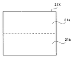
- FIG. 2 is a diagram for explaining division of an endoscopic image.
- FIG. 2 shows that the endoscopic image 21X is divided into a plurality, here two. Specifically, one frame of the endoscopic image 21X is divided into two pixel regions 21a and 21b.
- the image signal of each pixel area includes a plurality of pieces of pixel information in the pixel area and is transmitted to the video processor 3 in parallel.
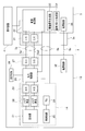
- FIG. 3 is a block diagram showing a configuration of the endoscope system 1.
- the universal cable 5 is connected to the camera head 13, and the universal cable 5 extending from the camera head 13 is connected to the video processor 3 via the connector 3a.
- the universal cable 5 is inserted with a plurality of optical fibers 5a and a plurality of electrical wires 5b.
- the plurality of wirings 5b includes a metal transmission member such as a metal conductor, and constitutes a metal transmission unit for transmitting various types of information, as will be described later.
- the plurality of optical fibers arranged in the universal cable 5 are made of, for example, quartz glass with a very small diameter (for example, a diameter of 0.125 mm) and are very fragile. After the primary coating with the curable resin, it is further covered with a protective tube for protection. At this time, a plurality of primary-coated optical fibers may be collectively covered with a protective tube, or each of the primary-coated optical fibers may be individually covered with a protective tube.
- the metal transmission members arranged in the universal cable 5 may be covered with a protective tube, for example, or may be protected together with a protective tube after two or more are insulated.
- the arrangement of the plurality of optical fibers and the metal transmission member in the universal cable 5 may be appropriate, but for example, it may be symmetric with respect to the central axis of the cable.
- the universal cable 5 can be bent in any direction with the same curvature, and it is not easy to bend in a specific direction and difficult to bend in other specific directions. The handling of the cable 5 can be facilitated.
- the metal transmission members are arranged symmetrically so as to surround a plurality of optical fibers grouped together as the axis center, or the metal wires grouped together as the axis center.
- a plurality of optical fibers are arranged symmetrically so as to surround the periphery.
- the metal transmission member can function as a tension member that protects the optical fiber from the tension applied to the universal cable 5.
- the image sensor 14 in the camera head 13 is a CMOS image sensor, and includes a light receiving unit 21 having a light receiving surface, a noise removing unit 22, an analog-digital conversion unit (hereinafter abbreviated as A / D) 23, and a timing generator ( (Hereinafter abbreviated as TG) 24 and a control circuit 25.
- a / D analog-digital conversion unit
- TG timing generator
- the image sensor 14 is a CMOS image sensor, and the light receiving surface of the light receiving unit 21 is divided into two pixel regions 21a and 21b.
- the image signal photoelectrically converted by the light receiving unit 21 is output to the noise removing unit 22.
- the image signals of the two pixel regions 21a and 21b are output to two noise removal circuits in the noise removal unit 22, respectively.
- the noise removing unit 22 outputs the image signal for each pixel area from which noise has been removed to the A / D 23.
- the imaging device 14 constitutes an imaging unit that images the inside of the subject and outputs two or more digital signals, here, digital signals of two pixel regions.
- the image sensor 14 is divided into two pixel regions, but may be divided into three or more pixel regions.
- the two or more digital signals output from the image sensor 14 correspond to two or more imaging areas obtained by dividing an image obtained by imaging the subject.
- the A / D 23 includes an analog / digital conversion circuit for each pixel region, converts the image signal from an analog signal to a digital signal, and outputs the converted signal to the output control unit 26.
- the output of each analog-digital conversion circuit of the A / D 23 is shown by one line, but the image signal output from each analog-digital conversion circuit is a parallel signal.
- the TG 24 generates various timing signals and outputs them to the control circuit 25.
- the control circuit 25 drives the light receiving unit 21, the noise removing unit 22, and the A / D 23 based on various timing signals.
- the camera head 13 includes an output control unit 26, an electro-optic conversion unit 27, and an EEPROM 28 in addition to the image sensor 14.
- the output control unit 26 outputs the image signal from the A / D 23 to the electro-optic conversion unit 27, reads the data in the EEPROM 28, and outputs it to the video processor 3.
- the configuration of the output control unit 26 will be described later.
- the electro-optic conversion unit 27 is provided in the camera head 13.
- the electro-optic converter 27 has two electro-optic converters (E / O) corresponding to the two image signals from the output controller 26.
- the two electro-optic converters are connected to two optical fibers 5a1 and 5a2 inserted into the universal cable 5, respectively.
- the electro-optic conversion unit 27 includes a plurality of electro-optic converters, converts a plurality (here, two) of digital signals output from the image sensor 14 into optical signals, and converts a plurality of (here, two) electro-optic conversions. Output in parallel.
- the plurality of optical fibers 5a include a plurality (here, two) of optical transmission members, and a plurality (here, two) of optical signals output from the electro-optic conversion unit 27 are a plurality of (here, two) light.
- An optical transmission unit adapted to transmit in parallel by the transmission member is configured.
- the EEPROM 28 stores identification information (hereinafter referred to as ID) of the camera head 13 and the like.
- ID identification information
- the EEPROM 28 is a rewritable nonvolatile memory.
- the EEPROM 28 may store not only the ID but also various information related to image processing and information related to image processing such as an image processing program (hereinafter referred to as image processing information). That is, the EEPROM 28 constitutes a recording unit in which predetermined information related to the endoscope 2 is recorded.
- the ID is endoscope scope information, camera head serial number, and the like.
- the various information includes defective pixel information of the image sensor 14, white balance information, color variation correction information, adjustment parameters, and the like.
- the image processing program is an image processing program applied to the image signal output from the camera head 13.
- the image processing program is transmitted from the camera head 13 to the video processor 3, and the video processor 3 executes image processing on the image signal from the camera head 13 using the received image processing program.
- the output control unit 26 and the EEPROM 28 are mounted on, for example, the circuit board 15 provided in the operation unit 13a.
- the image sensor 14, the output control unit 26, the electro-optic conversion unit 27, and the EEPROM 28 are provided in the camera head 13.
- a plurality of optical fibers are provided in parallel corresponding to the number of image signals output from the image sensor 14 in the universal cable 5.
- a photoelectric conversion unit 31 is provided in the connector 3a.
- the photoelectric conversion unit 31 has two photoelectric conversion circuits (O / E) corresponding to the two optical fibers 5a1 and 5a2. That is, the photoelectric conversion unit 31 is provided around the connector 3a at the end of the universal cable 5, and converts an optical signal transmitted through the plurality of optical fibers 5a serving as an optical transmission unit into an electrical signal.
- the video processor 3 includes an image processing unit 32, a drive signal generation unit 33, and a reference clock generation unit 34.
- the image processing unit 32 combines the image signals received via the photoelectric conversion unit 31 and executes predetermined image processing on the received image signal based on the received image processing information. Generate an image.
- the generated image signal of the endoscopic image is supplied to the display device 4, and the endoscopic image is displayed on the display screen.
- the image processing unit 32 has a plurality of image processing programs or circuits corresponding to the type of endoscope, and image processing corresponding to the received ID (image processing information), for example, color adjustment processing is determined. If so, the image processing unit 32 selects an image processing program or circuit corresponding to the ID, and executes appropriate processing on the received image signal. Further, the image processing unit 32 may perform image processing using information (image processing information) such as received defective pixel information on the received image signal. In addition, the image processing unit 32 may perform image processing using the received image processing program (image processing information) on the received image signal.
- the drive signal generation unit 33 generates a drive signal for driving various circuits in the image sensor 14 and supplies the drive signal to the camera head 13 via a part of the plurality of wirings 5b.
- the reference clock generation unit 34 generates a reference clock that serves as a reference of timing for driving various circuits in the video processor 3.
- the drive signal generation unit 33 and the reference clock generation unit 34 are provided in the video processor 3 here, but may be provided in the camera head 13.
- the camera head 13 and the video processor 3 have power supply circuits 35 and 36 as power supply units, respectively.
- the power supply circuits 35 and 36 are connected via a power supply line 5 c inserted into the universal cable 5.
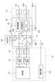
- FIG. 4 is a diagram for explaining the configuration of the output control unit 26.
- the output control unit 26 includes a data switching unit 41 and a signal control unit 42.
- the data switching unit 41 is connected to the A / D 23 and has a plurality (two in this case) of input terminals, an input terminal connected to the EEPROM 28, and a plurality of (here, two) outputs connected to the signal control unit 42. And an output end connected to one wiring 5b1a among the plurality of wirings.
- the data switching unit 41 includes two switches SW1 and SW2.
- the data switching unit 41 has three input terminals, one input terminal I1 is connected to one analog-digital conversion circuit of the A / D 23, and one input terminal I2 is another analog terminal of the A / D 23.
- the other input terminal I3 is connected to the EEPROM 28 and is connected to the digital conversion circuit.
- the data switching unit 41 has two output terminals O1 and O2, and the two output terminals O1 and O2 can be connected to two electro-optic converters of the E / O 27 via the signal control unit 42, respectively. Yes.
- the switch SW1 has two input terminals I1 and I3 and an output terminal O1, and the output terminal of the switch SW1 can be selectively connected to one of the two input terminals I1 and I3 based on the control signal SC. It has become.
- the switch SW2 has one input terminal I2 and an output terminal O2, and the output terminal of the switch SW2 can be selectively connected to the input terminal I2 based on the control signal SC. That is, in the data switching unit 41, the switches SW1 and SW2 are switched based on the control signal SC from the signal control unit 42, whereby the connection state between each input terminal and the plurality of output terminals is switched.
- the signal control unit 42 includes a determination control unit 42a and a parallel / serial conversion unit (hereinafter abbreviated as P / S) 42b.
- the determination control unit 42a is a circuit that determines whether or not the data amount of information read from the EEPROM 28 is equal to or greater than a predetermined threshold value TH and performs switching control of the two switches SW1 and SW2 of the data switching unit 41.
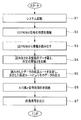
- FIG. 5 is a flowchart showing the operation of the signal control unit 42.
- FIG. 5 shows an example of the flow of processing when the endoscope 2 is connected to the video processor 3 and the endoscope system 1 is activated.
- the determination control unit 42a controls the data switching unit 41 so as to connect the EEPROM 28 and the signal control unit 42 (S2). Specifically, the connection state between the input end and the output end in the data switching unit 41 is switched so that the output end O1 of the switch SW1 and the input end I3 of the EEPROM 28 are connected.
- the determination control unit 42a outputs a data read signal RC to the EEPROM 28, and reads information stored in the EEPROM 28, here information on image processing, from the EEPROM 28 via the data switching unit 41 (S3). ). That is, the signal control unit 42 starts reading predetermined information from the EEPROM 28 based on activation of the power supply circuit 35 that is a power supply unit.
- the determination control unit 42a can grasp the data amount of information when reading the information stored in the EEPROM 28. Therefore, the determination control unit 42a compares the data amount of information to be read with the predetermined threshold value TH (S4).
- the determination control unit 42a determines whether the data amount of information read from the EEPROM 28 is greater than or equal to a predetermined threshold TH from the comparison result of S4, determines a transmission route of the read data based on the determination result, The read data is output to the determined transmission route (S5).
- the determination control unit 42a selects one wiring 5b1a among the plurality of wirings 5b as a transmission route. For example, when the information to be read is ID or defective pixel information with a small amount of data, an electrical wiring is selected as the transmission route, and the information is transmitted to the video processor 3 through the wiring.
- the determination control unit 42a transmits one optical fiber 5a1 out of the two optical fibers 5a of the electro-optic conversion unit 27. Select as. For example, when the information to be read is an image processing program with a large amount of data, an optical fiber is selected as the transmission route, and the information is transmitted to the video processor 3 through the optical fiber.
- the determination control unit 42a determines whether the information read from the EEPROM 28 is transmitted via the metal transmission member or the optical transmission member based on the data amount of the information read from the EEPROM 28. Then, when the data amount of information read from the EEPROM 28 is equal to or greater than a predetermined value, the determination control unit 42a controls the data switching unit 41 so that the information read from the EEPROM 28 is transmitted via the optical transmission member.
- the information read from the EEPROM 28 is converted into a serial signal in the P / S 42b and then output through the determined transmission route.
- the information is an image processing program having a large amount of data
- the information is transmitted quickly by optical transmission, so that transmission of the image signal can be started quickly.
- the determination control unit 42a controls the data switching unit 41 to connect the A / D 23 and the signal control unit 42 (S6). Specifically, as shown by a two-dot chain line in FIG. 4, the data switching is performed so that the input terminal I1 and the output terminal O1 of the switch SW1 are connected and the input terminal I2 and the output terminal O2 of the switch SW2 are connected. The connection state between the input end and the output end in the unit 41 is switched.
- the determination control unit 42a transmits the control signal SS to the control circuit 25 of the image sensor 14 so as to output two image signals after the connection state of the data switching unit 41 is switched, and transmits the two image signals to the electro-optic conversion unit 27 (S7).
- the two image signals are converted into serial signals by the P / S 42 b and then output to the electro-optic conversion unit 27.
- the universal cable 5 uses the plural (here, two) optical transmission members that transmit the optical signals output from the electro-optic conversion units and the data output from the signal control unit 42. It is the cable comprised by the metal transmission member which transmits.
- the signal control unit 42 selectively converts at least one of the digital signal that is the image signal output from the image sensor 14 or the information read from the EEPROM 28 into serial data and outputs the serial data.
- the data switching unit 41 switches the information read from the EEPROM 28 to be transferred to the video processor 3 by the signal control unit 42 and then transferred to the video processor 3 by the signal control unit.
- the information is transmitted by wiring, but may be transmitted by an optical fiber.
- the two image signals in the two pixel regions 21a and 21b are transmitted to the video processor 3.
- image processing information is transmitted to the video processor 3
- the two image signals in the two pixel regions 21a and 21b are transmitted to the video processor 3.
- the image signal is transmitted to the video processor 3 through the optical fiber selected as the transmission route.
- the wiring is selected as the transmission route, and the electrical wiring is performed. It may be transmitted to the video processor 3.
- an endoscope system that transmits an image signal as an optical signal
- an endoscope system and an endoscope that can appropriately transmit information related to image processing on the image signal to a processing device.
- a mirror can be provided.
- the endoscope is a rigid endoscope, but may be a flexible endoscope whose insertion portion is flexible.
Landscapes
- Health & Medical Sciences (AREA)
- Life Sciences & Earth Sciences (AREA)
- Surgery (AREA)
- Physics & Mathematics (AREA)
- Engineering & Computer Science (AREA)
- Optics & Photonics (AREA)
- Biomedical Technology (AREA)
- Veterinary Medicine (AREA)
- Biophysics (AREA)
- Pathology (AREA)
- Radiology & Medical Imaging (AREA)
- Nuclear Medicine, Radiotherapy & Molecular Imaging (AREA)
- Public Health (AREA)
- Heart & Thoracic Surgery (AREA)
- Medical Informatics (AREA)
- Molecular Biology (AREA)
- Animal Behavior & Ethology (AREA)
- General Health & Medical Sciences (AREA)
- Signal Processing (AREA)
- Multimedia (AREA)
- Astronomy & Astrophysics (AREA)
- General Physics & Mathematics (AREA)
- Endoscopes (AREA)
- Studio Devices (AREA)
- Instruments For Viewing The Inside Of Hollow Bodies (AREA)
Abstract
L'invention concerne un système d'endoscope 1 qui comprend : un élément de capture d'image 14 qui délivre des signaux numériques ; une EEPROM 28 dans laquelle des informations prédéterminées relatives à un endoscope sont enregistrées ; une unité de commande de signal 42 apte à convertir sélectivement, en données en série, les données des signaux numériques délivrés par l'élément de capture d'image 14 et/ou les données des informations prédéterminées de l'EEPROM 28, et délivrer les données en série ; une unité de conversion photoélectrique 27 qui convertit, en signaux optiques, les données délivrées par l'unité de commande de signal 42, et qui délivre les signaux optiques ; un câble universel ; et une unité de commutation de données 41 qui réalise une commutation de telle sorte que les signaux numériques sont transférés au moyen de l'unité de commande de signal 42 une fois que les informations prédéterminées provenant de l'EEPROM 28 sont transférées au moyen de l'unité de commande de signal 42.
Priority Applications (4)
| Application Number | Priority Date | Filing Date | Title |
|---|---|---|---|
| CN201680018423.3A CN107427199B (zh) | 2016-03-07 | 2016-09-15 | 内窥镜系统和内窥镜 |
| JP2016576001A JP6161841B1 (ja) | 2016-03-07 | 2016-09-15 | 内視鏡システム及び内視鏡 |
| EP16893568.2A EP3263014A4 (fr) | 2016-03-07 | 2016-09-15 | Système d'endoscope, et endoscope |
| US15/706,678 US10716459B2 (en) | 2016-03-07 | 2017-09-16 | Endoscope system and endoscope |
Applications Claiming Priority (2)
| Application Number | Priority Date | Filing Date | Title |
|---|---|---|---|
| JP2016043617 | 2016-03-07 | ||
| JP2016-043617 | 2016-03-07 |
Related Child Applications (1)
| Application Number | Title | Priority Date | Filing Date |
|---|---|---|---|
| US15/706,678 Continuation US10716459B2 (en) | 2016-03-07 | 2017-09-16 | Endoscope system and endoscope |
Publications (1)
| Publication Number | Publication Date |
|---|---|
| WO2017154244A1 true WO2017154244A1 (fr) | 2017-09-14 |
Family
ID=59789185
Family Applications (1)
| Application Number | Title | Priority Date | Filing Date |
|---|---|---|---|
| PCT/JP2016/077265 Ceased WO2017154244A1 (fr) | 2016-03-07 | 2016-09-15 | Système d'endoscope, et endoscope |
Country Status (5)
| Country | Link |
|---|---|
| US (1) | US10716459B2 (fr) |
| EP (1) | EP3263014A4 (fr) |
| JP (1) | JP6161841B1 (fr) |
| CN (1) | CN107427199B (fr) |
| WO (1) | WO2017154244A1 (fr) |
Families Citing this family (10)
| Publication number | Priority date | Publication date | Assignee | Title |
|---|---|---|---|---|
| US10582832B2 (en) | 2013-01-17 | 2020-03-10 | Stryker Corporation | System for altering functions of at least one surgical device dependent upon information saved in an endoscope related to the endoscope |
| US10537236B2 (en) | 2013-01-17 | 2020-01-21 | Stryker Corporation | Anti-fogging device for endoscope |
| EP3378375A1 (fr) * | 2017-03-23 | 2018-09-26 | Stryker Corporation | Système permettant de modifier les fonctions d'au moins un dispositif chirurgical dépendant des informations sauvegardées dans un endoscope lié à l'endoscope |
| US10722102B2 (en) | 2017-09-05 | 2020-07-28 | Arthrex, Inc. | Endoscope field stop encoding system and method |
| CN110367910A (zh) * | 2019-08-23 | 2019-10-25 | 重庆金山科技(集团)有限公司 | 内窥镜接头、内窥镜镜体、内窥镜冷光源及内窥镜系统 |
| DE102020119172A1 (de) * | 2020-07-21 | 2022-01-27 | Schölly Fiberoptic GmbH | Endoskopanordnung |
| CN116507262B (zh) * | 2020-10-27 | 2025-09-23 | 深圳迈瑞生物医疗电子股份有限公司 | 内窥镜摄像系统及其影像数据传输装置 |
| CN118317733A (zh) * | 2021-12-30 | 2024-07-09 | 武汉迈瑞生物医疗科技有限公司 | 内窥镜摄像系统、内窥镜装置及其数据传输线缆 |
| CN115334277B (zh) * | 2022-06-30 | 2024-02-09 | 极限人工智能有限公司 | 一种电子内窥镜、电子内窥镜视频传输系统及方法 |
| CN120475121B (zh) * | 2025-06-11 | 2026-01-16 | 思脉得(嘉兴)医疗科技有限公司 | 基于高速SerDes芯片的多模态内窥镜视频传输线束系统及方法 |
Citations (4)
| Publication number | Priority date | Publication date | Assignee | Title |
|---|---|---|---|---|
| JP2009028081A (ja) * | 2007-07-24 | 2009-02-12 | Olympus Medical Systems Corp | 受信装置 |
| WO2012046856A1 (fr) * | 2010-10-08 | 2012-04-12 | オリンパスメディカルシステムズ株式会社 | Dispositif d'imagerie |
| WO2012132096A1 (fr) * | 2011-03-29 | 2012-10-04 | オリンパスメディカルシステムズ株式会社 | Adaptateur d'endoscope, processeur d'endoscope et système d'endoscope |
| WO2014171332A1 (fr) * | 2013-04-19 | 2014-10-23 | オリンパスメディカルシステムズ株式会社 | Dispositif de capture et dispositif de traitement d'image |
Family Cites Families (21)
| Publication number | Priority date | Publication date | Assignee | Title |
|---|---|---|---|---|
| JPS58141135A (ja) * | 1981-10-20 | 1983-08-22 | 富士写真フイルム株式会社 | 固体イメ−ジセンサを用いた内視鏡の画像伝送方式 |
| DE19947811C2 (de) * | 1999-10-05 | 2002-06-20 | Winter & Ibe Olympus | Endoskop mit elektrischer Einrichtung und Lichtleiter |
| JP2008036356A (ja) * | 2006-08-10 | 2008-02-21 | Olympus Corp | 電子内視鏡装置及び電子内視鏡システム |
| CN103002790B (zh) * | 2010-07-07 | 2015-09-30 | 奥林巴斯医疗株式会社 | 内窥镜系统以及内窥镜系统的动作方法 |
| CN103250406B (zh) * | 2010-12-14 | 2017-03-01 | 奥林巴斯株式会社 | 摄像装置 |
| AU2012262258B2 (en) * | 2011-05-31 | 2015-11-26 | Lightlab Imaging, Inc. | Multimodal imaging system, apparatus, and methods |
| JP5784382B2 (ja) * | 2011-06-20 | 2015-09-24 | オリンパス株式会社 | 電子内視鏡装置 |
| JP5784383B2 (ja) * | 2011-06-20 | 2015-09-24 | オリンパス株式会社 | 電子内視鏡装置 |
| JP5904829B2 (ja) * | 2012-03-12 | 2016-04-20 | オリンパス株式会社 | 内視鏡システム |
| JP5869194B1 (ja) * | 2014-07-02 | 2016-02-24 | オリンパス株式会社 | 撮像装置、内視鏡システム、および、内視鏡装置 |
| WO2016035363A1 (fr) * | 2014-09-01 | 2016-03-10 | オリンパス株式会社 | Système de communication optique et système endoscopique |
| US10313629B2 (en) * | 2015-04-30 | 2019-06-04 | Sony Olympus Medical Solutions Inc. | Medical observation device |
| US10405733B2 (en) * | 2015-04-30 | 2019-09-10 | Sony Olympus Medical Solutions Inc. | Medical signal processing device and medical observation system |
| JP6892087B2 (ja) * | 2015-06-12 | 2021-06-18 | ソニー・オリンパスメディカルソリューションズ株式会社 | 医療用画像取得システムおよび医療用撮像装置 |
| JP6654051B2 (ja) * | 2016-01-15 | 2020-02-26 | ソニー・オリンパスメディカルソリューションズ株式会社 | 医療用観察システム |
| JP6675202B2 (ja) * | 2016-01-15 | 2020-04-01 | ソニー・オリンパスメディカルソリューションズ株式会社 | 医療用信号処理装置、及び医療用観察システム |
| JP6639920B2 (ja) * | 2016-01-15 | 2020-02-05 | ソニー・オリンパスメディカルソリューションズ株式会社 | 医療用信号処理装置、及び医療用観察システム |
| WO2017145418A1 (fr) * | 2016-02-25 | 2017-08-31 | オリンパス株式会社 | Système d'endoscope et procédé de fonctionnement de système d'endoscope |
| JP6121078B1 (ja) * | 2016-03-03 | 2017-04-26 | オリンパス株式会社 | 内視鏡システム、内視鏡システムの作動方法 |
| WO2017149814A1 (fr) * | 2016-03-04 | 2017-09-08 | オリンパス株式会社 | Système d'endoscope et endoscope |
| WO2018079329A1 (fr) * | 2016-10-31 | 2018-05-03 | オリンパス株式会社 | Système d'endoscope et endoscope |
-
2016
- 2016-09-15 WO PCT/JP2016/077265 patent/WO2017154244A1/fr not_active Ceased
- 2016-09-15 CN CN201680018423.3A patent/CN107427199B/zh active Active
- 2016-09-15 EP EP16893568.2A patent/EP3263014A4/fr not_active Withdrawn
- 2016-09-15 JP JP2016576001A patent/JP6161841B1/ja active Active
-
2017
- 2017-09-16 US US15/706,678 patent/US10716459B2/en active Active
Patent Citations (4)
| Publication number | Priority date | Publication date | Assignee | Title |
|---|---|---|---|---|
| JP2009028081A (ja) * | 2007-07-24 | 2009-02-12 | Olympus Medical Systems Corp | 受信装置 |
| WO2012046856A1 (fr) * | 2010-10-08 | 2012-04-12 | オリンパスメディカルシステムズ株式会社 | Dispositif d'imagerie |
| WO2012132096A1 (fr) * | 2011-03-29 | 2012-10-04 | オリンパスメディカルシステムズ株式会社 | Adaptateur d'endoscope, processeur d'endoscope et système d'endoscope |
| WO2014171332A1 (fr) * | 2013-04-19 | 2014-10-23 | オリンパスメディカルシステムズ株式会社 | Dispositif de capture et dispositif de traitement d'image |
Non-Patent Citations (1)
| Title |
|---|
| See also references of EP3263014A4 * |
Also Published As
| Publication number | Publication date |
|---|---|
| JP6161841B1 (ja) | 2017-07-12 |
| EP3263014A1 (fr) | 2018-01-03 |
| JPWO2017154244A1 (ja) | 2018-03-15 |
| CN107427199A (zh) | 2017-12-01 |
| EP3263014A4 (fr) | 2018-11-21 |
| US10716459B2 (en) | 2020-07-21 |
| CN107427199B (zh) | 2019-10-25 |
| US20180014716A1 (en) | 2018-01-18 |
Similar Documents
| Publication | Publication Date | Title |
|---|---|---|
| JP6161841B1 (ja) | 内視鏡システム及び内視鏡 | |
| JP6113383B1 (ja) | 内視鏡システム及び内視鏡 | |
| CN107306492B (zh) | 内窥镜系统和内窥镜系统的工作方法 | |
| CN107920728B (zh) | 内窥镜系统 | |
| JP5384409B2 (ja) | 内視鏡装置におけるcmos撮像素子の作動方法 | |
| US10313629B2 (en) | Medical observation device | |
| US10405733B2 (en) | Medical signal processing device and medical observation system | |
| JP2008068021A (ja) | 電子内視鏡装置 | |
| US20140320619A1 (en) | Imaging unit and imaging system | |
| JP6082658B2 (ja) | 撮像素子および内視鏡装置 | |
| US10149600B2 (en) | Medical signal processing device and medical observation system | |
| JP5932191B1 (ja) | 伝送システムおよび処理装置 | |
| JP2015181586A (ja) | 内視鏡装置、カメラヘッド、及び制御装置 | |
| JP2013054198A (ja) | 内視鏡装置、内視鏡システム及び内視鏡装置本体部 |
Legal Events
| Date | Code | Title | Description |
|---|---|---|---|
| ENP | Entry into the national phase |
Ref document number: 2016576001 Country of ref document: JP Kind code of ref document: A |
|
| REEP | Request for entry into the european phase |
Ref document number: 2016893568 Country of ref document: EP |
|
| NENP | Non-entry into the national phase |
Ref country code: DE |