WO2017154287A1 - Machine dynamo-électrique - Google Patents
Machine dynamo-électrique Download PDFInfo
- Publication number
- WO2017154287A1 WO2017154287A1 PCT/JP2016/085402 JP2016085402W WO2017154287A1 WO 2017154287 A1 WO2017154287 A1 WO 2017154287A1 JP 2016085402 W JP2016085402 W JP 2016085402W WO 2017154287 A1 WO2017154287 A1 WO 2017154287A1
- Authority
- WO
- WIPO (PCT)
- Prior art keywords
- teeth
- angle
- stator
- rotor
- tip width
- Prior art date
- Legal status (The legal status is an assumption and is not a legal conclusion. Google has not performed a legal analysis and makes no representation as to the accuracy of the status listed.)
- Ceased
Links
Images





Classifications
-
- H—ELECTRICITY
- H02—GENERATION; CONVERSION OR DISTRIBUTION OF ELECTRIC POWER
- H02K—DYNAMO-ELECTRIC MACHINES
- H02K1/00—Details of the magnetic circuit
- H02K1/06—Details of the magnetic circuit characterised by the shape, form or construction
- H02K1/12—Stationary parts of the magnetic circuit
- H02K1/14—Stator cores with salient poles
-
- H—ELECTRICITY
- H02—GENERATION; CONVERSION OR DISTRIBUTION OF ELECTRIC POWER
- H02K—DYNAMO-ELECTRIC MACHINES
- H02K1/00—Details of the magnetic circuit
- H02K1/06—Details of the magnetic circuit characterised by the shape, form or construction
- H02K1/22—Rotating parts of the magnetic circuit
-
- H—ELECTRICITY
- H02—GENERATION; CONVERSION OR DISTRIBUTION OF ELECTRIC POWER
- H02K—DYNAMO-ELECTRIC MACHINES
- H02K1/00—Details of the magnetic circuit
- H02K1/06—Details of the magnetic circuit characterised by the shape, form or construction
- H02K1/22—Rotating parts of the magnetic circuit
- H02K1/27—Rotor cores with permanent magnets
-
- H—ELECTRICITY
- H02—GENERATION; CONVERSION OR DISTRIBUTION OF ELECTRIC POWER
- H02K—DYNAMO-ELECTRIC MACHINES
- H02K1/00—Details of the magnetic circuit
- H02K1/06—Details of the magnetic circuit characterised by the shape, form or construction
- H02K1/22—Rotating parts of the magnetic circuit
- H02K1/27—Rotor cores with permanent magnets
- H02K1/2706—Inner rotors
- H02K1/272—Inner rotors the magnetisation axis of the magnets being perpendicular to the rotor axis
- H02K1/274—Inner rotors the magnetisation axis of the magnets being perpendicular to the rotor axis the rotor consisting of two or more circumferentially positioned magnets
- H02K1/2753—Inner rotors the magnetisation axis of the magnets being perpendicular to the rotor axis the rotor consisting of two or more circumferentially positioned magnets the rotor consisting of magnets or groups of magnets arranged with alternating polarity
- H02K1/276—Magnets embedded in the magnetic core, e.g. interior permanent magnets [IPM]
-
- H—ELECTRICITY
- H02—GENERATION; CONVERSION OR DISTRIBUTION OF ELECTRIC POWER
- H02K—DYNAMO-ELECTRIC MACHINES
- H02K1/00—Details of the magnetic circuit
- H02K1/06—Details of the magnetic circuit characterised by the shape, form or construction
- H02K1/22—Rotating parts of the magnetic circuit
- H02K1/27—Rotor cores with permanent magnets
- H02K1/2706—Inner rotors
- H02K1/272—Inner rotors the magnetisation axis of the magnets being perpendicular to the rotor axis
- H02K1/274—Inner rotors the magnetisation axis of the magnets being perpendicular to the rotor axis the rotor consisting of two or more circumferentially positioned magnets
- H02K1/2753—Inner rotors the magnetisation axis of the magnets being perpendicular to the rotor axis the rotor consisting of two or more circumferentially positioned magnets the rotor consisting of magnets or groups of magnets arranged with alternating polarity
- H02K1/276—Magnets embedded in the magnetic core, e.g. interior permanent magnets [IPM]
- H02K1/2766—Magnets embedded in the magnetic core, e.g. interior permanent magnets [IPM] having a flux concentration effect
-
- H—ELECTRICITY
- H02—GENERATION; CONVERSION OR DISTRIBUTION OF ELECTRIC POWER
- H02K—DYNAMO-ELECTRIC MACHINES
- H02K21/00—Synchronous motors having permanent magnets; Synchronous generators having permanent magnets
- H02K21/12—Synchronous motors having permanent magnets; Synchronous generators having permanent magnets with stationary armatures and rotating magnets
- H02K21/14—Synchronous motors having permanent magnets; Synchronous generators having permanent magnets with stationary armatures and rotating magnets with magnets rotating within the armatures
- H02K21/16—Synchronous motors having permanent magnets; Synchronous generators having permanent magnets with stationary armatures and rotating magnets with magnets rotating within the armatures having annular armature cores with salient poles
-
- H—ELECTRICITY
- H02—GENERATION; CONVERSION OR DISTRIBUTION OF ELECTRIC POWER
- H02K—DYNAMO-ELECTRIC MACHINES
- H02K29/00—Motors or generators having non-mechanical commutating devices, e.g. discharge tubes or semiconductor devices
- H02K29/03—Motors or generators having non-mechanical commutating devices, e.g. discharge tubes or semiconductor devices with a magnetic circuit specially adapted for avoiding torque ripples or self-starting problems
-
- H—ELECTRICITY
- H02—GENERATION; CONVERSION OR DISTRIBUTION OF ELECTRIC POWER
- H02K—DYNAMO-ELECTRIC MACHINES
- H02K2201/00—Specific aspects not provided for in the other groups of this subclass relating to the magnetic circuits
- H02K2201/06—Magnetic cores, or permanent magnets characterised by their skew
-
- H—ELECTRICITY
- H02—GENERATION; CONVERSION OR DISTRIBUTION OF ELECTRIC POWER
- H02K—DYNAMO-ELECTRIC MACHINES
- H02K2213/00—Specific aspects, not otherwise provided for and not covered by codes H02K2201/00 - H02K2211/00
- H02K2213/03—Machines characterised by numerical values, ranges, mathematical expressions or similar information
Definitions
- the present invention relates to a concentrated winding rotating electric machine using a permanent magnet.
- a motor for an electrified vehicle such as a hybrid vehicle is driven at a high speed rotation (10000 r / min or more) comparable to or higher than the engine rotation speed (for example, 6000 r / min), and therefore has a wide operating range of rotation speed.
- a flat motor is preferred for a motor that has characteristics and is sandwiched between an engine and a transmission.
- torque is generated by the magnetic attractive force generated between the stator and the rotor, but the magnetic attractive force fluctuates depending on the rotor position, so it matches the natural frequency of the outer periphery of the stator of the motor. Then, motor noise is generated.
- the relationship between the tip width of the teeth of the stator and the pitch of the magnets embedded in the rotor is limited to numerical values, thereby reducing the distortion rate of the induced voltage waveform. It is reduced (for example, refer patent document 1).
- the conventional rotating electric machine as described above cannot sufficiently suppress vibration due to fluctuations in suction force, and is required to reduce vibration more efficiently.
- the present invention has been made to solve the above-described problems, and an object of the present invention is to obtain a rotating electrical machine that can more efficiently suppress vibration caused by fluctuations in suction force.
- a rotating electrical machine includes a stator having a stator core, a rotor core, and a plurality of permanent magnets fixed to the rotor core, and is rotatable with respect to the stator.
- the stator core has an annular core back and a plurality of teeth projecting radially inward from the core back, and a slot is provided between the teeth of the stator core.
- the ratio of the number of poles to the number of slots is 2: 3, the electrical angle of the teeth tip width, which is the width of the tip of the teeth in the circumferential direction of the stator, is ⁇ , the rotation center of the rotor and one permanent
- the electrical angle of the polar arc angle which is an angle formed by two straight lines connecting the corners on the rotor surface side of the magnet, is ⁇ and the number of pole pairs is P
- the electrical angle ⁇ 0.2 ° ⁇ It is within the range of P.
- the rotating electrical machine includes a stator having a stator core, a rotor core, and a plurality of permanent magnets fixed to the rotor core, and is rotatable with respect to the stator.
- the stator core has an annular core back and a plurality of teeth protruding radially inward from the core back, and slots are provided between the teeth of the stator core.
- the ratio of the number of poles to the number of slots is 2: 3
- the electrical angle of the teeth tip width which is the width dimension of the teeth tip in the circumferential direction of the stator, is ⁇
- the rotation center of the rotor is one piece.
- the rotating electrical machine includes a stator having a stator core, a rotor core, and a plurality of permanent magnets fixed to the rotor core, and is rotatable with respect to the stator.
- the stator core has an annular core back and a plurality of teeth protruding radially inward from the core back, and slots are provided between the teeth of the stator core.
- the ratio of the number of poles to the number of slots is 2: 3
- the electrical angle of the teeth tip width which is the width dimension of the teeth tip in the circumferential direction of the stator, is ⁇
- the rotation center of the rotor is one piece.
- ⁇ ⁇ 2.5 ⁇ + 319.7 (0 ⁇ ⁇ 180) [deg]
- ⁇ is the electric angle of the polar arc angle, which is an angle formed by two straight lines connecting the corners on the rotor surface side of the permanent magnet
- ⁇ is ⁇ 1
- the plurality of different types of teeth tip widths are combined in the axial direction of the stator, the minimum electrical angle of at least one type of teeth tip width is smaller than ⁇ 1, and at least one type of teeth tip The maximum value of the electrical angle of the width is larger than ⁇ 1.
- the rotating electrical machine of the present invention can suppress vibration due to fluctuations in suction force by reducing the 6f component of the average suction force value of the teeth.
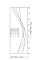
- FIG. 6 It is sectional drawing orthogonal to the axial direction of the rotary electric machine by Embodiment 1 of this invention. It is sectional drawing which expands and shows a part of rotary electric machine of FIG. 6 is a graph showing the rotational position dependence of the suction force of each phase of the first embodiment and the average value of the three-phase suction force according to the first embodiment. It is a graph which shows the teeth tip width
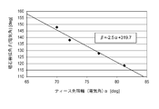
- FIG. 4 is a graph showing a relationship between teeth tip widths at which a fluctuation component of attractive force at each polar arc angle of the permanent magnet of the first embodiment is minimized. It is a graph which shows the relationship between 6f component of the attraction
- FIG. 10 is a graph showing a modification of the relationship between the axial length of the rotor core and the skew angle in the fourth embodiment. It is a graph which shows the relationship between the optimal skew angle from which the 6f component of the attraction
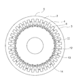
- FIG. 1 is a cross-sectional view perpendicular to the axial direction of a rotary electric machine according to Embodiment 1 of the present invention.
- the rotating electrical machine has a cylindrical stator 1 and a rotor 11 that is disposed inside the stator 1 and is rotatable with respect to the stator 1.
- the stator 1 has a cylindrical stator core 2 and a plurality of windings (not shown) attached to the stator core 2.
- the stator core 2 has an annular core back 3 and a plurality (36 in this example) of teeth 4 that protrude radially inward from the core back 3.
- the teeth 4 are arranged at an equal pitch in the circumferential direction of the stator 1.
- Slots 6 are formed between adjacent teeth 4. That is, the number of slots of the stator core 2 is 36. Each winding is wound around the tooth 4 and inserted into the slot 6.
- the winding phase order is U-phase, V-phase, W-phase in the counterclockwise direction of FIG.
- a three-phase alternating current having a phase difference of 120 degrees is applied to each phase.
- the rotor 11 has a cylindrical rotor core 12 and a plurality (24 in this example) of permanent magnets 13 embedded and fixed on the outer periphery of the rotor core 12.
- the outer peripheral surface of the rotor core 12 is opposed to the inner peripheral surface of the stator core 2, that is, the front end surface of the teeth 4 via a gap.
- Permanent magnets 13 are arranged at an equal pitch in the circumferential direction of the rotor 11. As each permanent magnet 13, a cuboid neodymium magnet is used, and one permanent magnet 13 is formed per pole. N and S shown in the figure indicate the poles of the permanent magnet 13, respectively.
- the direction of the magnetic flux of N is the direction toward the outer periphery of the rotor 11, and the direction of the magnetic flux of S is from the outer periphery of the rotor 11. It is the direction toward the lap.
- magnetic poles having different polarities alternately in the circumferential direction are formed on the outer periphery of the rotor 11.
- the rotating electrical machine of the first embodiment is a concentrated winding motor in which the ratio of the number of poles to the number of slots is 2: 3.
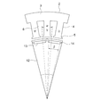
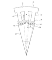
- FIG. 2 is an enlarged cross-sectional view showing a part of the rotating electric machine in FIG. 1, and shows the stator 1 and the rotor 11 per one pole pair.
- a tooth cage 5 is provided at the tip of each tooth 4, that is, at the end of each tooth 4 on the inner diameter side of the stator 1.
- the width dimension of the teeth 4 in the teeth bar 5 (the dimension of the teeth 4 in the circumferential direction of the stator 1) is larger than the width dimension of the portion of the teeth 4 closer to the core back 3 than the tooth bar 5 is.
- the width dimension of the tip of the tooth 4 including the tooth basket 5, that is, the electrical angle of the tip width of the tooth is ⁇ .
- ⁇ two straight lines connecting the rotation center of the rotor 11 and both end portions in the width direction of one tooth 4 in the cross section perpendicular to the axis of the rotating electrical machine form the rotation direction of the rotor 11. It was an angle.
- the electrical angle is a value obtained by multiplying the mechanical angle by the number of pole pairs.
- the number of poles is 24 and the number of pole pairs is 12, so that rotation between two straight lines as a mechanical angle is performed.
- a value obtained by multiplying the direction angle by 12 is ⁇ .
- the electrical angle of the polar arc angle of the permanent magnet 13 excluding the flux barrier 14 is ⁇ .
- ⁇ in the cross section perpendicular to the axis of the rotating electrical machine, the rotation center of the rotor 11 and the corners on the rotor surface side of one (one pole) permanent magnet 13 (both ends in the circumferential direction of the rotor 11).
- the suction force changes when the N pole approaches and moves away, and the same applies to the S pole. Accordingly, when viewed with the teeth 4 of each phase, the suction force varies twice each time the electrical angle rotates 360 °.
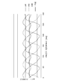
- FIG. 3 shows the electrical angle dependence of the attractive force of the teeth 4 of each phase when current is applied.
- FIG. 3 shows a case where the tip width of the tooth 4 is 77.0 ° in electrical angle, and the polar arc angle of the permanent magnet 13 is 128.1 ° in electrical angle.
- the suction force changes at a phase difference of 120 ° between the U phase, the V phase, and the W phase. Moreover, when the average value of the attraction
- the average value of the attractive force of each phase represents the average attractive force with respect to the rotating magnetic field. If the suction force of each phase is sinusoidal, the average value of the suction force is constant, that is, there is no fluctuation component. Therefore, the core back 3 and the teeth 4 vibrate due to the fluctuation of the average suction force value.
- the stator core 2 is fixed to a frame or the like (not shown) and has a natural frequency according to the deformation mode of the stator.
- the deformation mode is the ease of deformation when a force is applied in multiple directions to one round of the mechanical angle.
- the deformation mode 2 indicates that it is easily deformed into an elliptical shape.
- the natural frequency of the frame or the like matches the time frequency of the rotating magnetic field in the deformation mode 2, the frame resonates and sound is generated. Therefore, it is necessary to take noise reduction measures according to each deformation mode.
- Deformation mode 0 is a mode in which the force is a perfect circle and the force increases or decreases uniformly regardless of the rotational position, and may coincide with the natural frequency when there is no fluctuation component of the attractive force. Absent.
- the frame etc. resonates when the natural frequency of the frame or the like in the deformation mode 0 matches the frequency of the fluctuation component of the suction force. Sound. It is known that the natural frequency of the deformation mode 0 depends on the outer diameter of the motor, and the natural frequency decreases as the outer diameter increases.
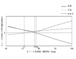
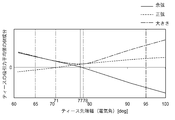
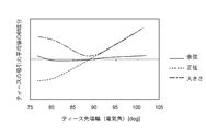
- FIG. 4 shows the tip width ⁇ of the teeth 4 and the amplitude of fluctuation of the average attractive force value of all the teeth 4.
- the attraction force average value of all the teeth 4 shown in FIG. 3 can be expressed as the following Expression 1.
- Equation 1 F is the average suction force value of all teeth 4
- C is the direct current component of the average suction force value of all teeth 4
- An is the cosine of the nth-order component of the average suction force value of all teeth 4
- Bn Indicates the sine of the nth-order component of the average suction force value of all teeth 4.
- FIG. 4 is a plot of the sine, cosine, and magnitude of the 6f component against the width of each tooth tip after the variation of the average value of the suction force of the teeth is divided into sine and cosine by Fourier transform.
- the tooth tip width having the smallest 6f component of the average suction force value of the teeth is an electrical angle of 77 °.
- the teeth tip widths are electrical angles of 78 ° and 71 °, respectively.
- FIG. 5 shows the relationship between the tip width of the teeth at the polar arc angle ⁇ of different permanent magnets 13 and the 6f component of the average attractive force of the teeth 4 in the same manner as in FIG.
- FIG. 5 shows that when the polar arc angle ⁇ of the permanent magnet 13 changes, it can be seen that the optimum value of the tooth tip width at which the 6f component of the average attractive force of the teeth 4 is minimized changes.
- FIG. 6 shows the result of plotting the optimum tooth tip width from which the magnitude of the 6f component of the suction force average value of the teeth 4 is minimized from FIG.
- the tooth tip width that minimizes the 6f component of the average attractive force of the teeth 4 can be uniquely determined, and the noise of the motor can be reduced.
- FIG. 7 shows the relationship. As shown in FIG. 7, the width of the tip of the teeth is minimized near an electrical angle of 72 °, and the polar arc angle ⁇ of the permanent magnet 13 at that time is 139.7 ° in electrical angle.
- the motor in which the permanent magnet 13 is embedded in the rotor core 12 has been described, but the surface magnet type in which the permanent magnet 13 is exposed on the outer periphery of the rotor core 12 as shown in FIG. The same effect can be obtained with the rotor of the above.
- Embodiment 2 a second embodiment of the present invention will be described.
- the basic configuration of the rotating electrical machine of the second embodiment is the same as that shown in FIG.
- a portion ⁇ 1 having an electrical angle smaller than ⁇ 1 and a portion ⁇ 2 having a tooth tip width larger than ⁇ 1 in electrical angle are combined in the axial direction of the stator 1.
- the average value of the radial suction force generated in all the teeth 4 is F1
- the least common multiple of the number of poles and the number of slots is S1
- the radial suction force S1 / is given to each tooth tip width ⁇ 1, ⁇ 2.
- the tooth tip widths at which the absolute values of the cosine and sine are minimum are ⁇ 1 and ⁇ 2, respectively.
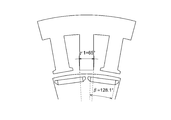
- FIG. 9 is a graph showing the relationship between the tooth tip width and the 6f component of the average attractive force of the teeth 4 when the polar arc angle ⁇ of the permanent magnet 13 of the rotating electrical machine of the second embodiment is 128.1 °.
- the values of electrical angles 65 ° ( ⁇ 1) and 95 ° ( ⁇ 2) are added.
- the 6f component of the suction force average value of the teeth 4 is reduced by combining different tooth tip widths in the axial direction.
- the 6f component of the suction force average value of the teeth 4 is viewed in FIG. 9, there is an angle at which the cosine or sine is zero.
- the electrical angle of 65 ° is smaller than Amin and the electrical angle is 95 ° larger than Amax.
- the cosine of the 6f component of the suction force average value of the teeth 4 is a positive and sine negative region, while the teeth tip width is larger than Amax. Is a region where the cosine of the 6f component of the average suction force value of the teeth is negative and the sine is positive. Accordingly, by combining both in the axial direction, the cosine and sine of the 6f component of the average suction force value of the teeth 4 are canceled.
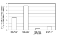
- FIG. 10 shows a combination of an electrical angle of 65 ° and an electrical angle of 95 ° when the pole arc angle of the magnet is 128.1 ° and the tip width of the teeth is 65 °, and the electrical angle is 95 °.
- the magnitude of the 6f component of the average suction force value of the teeth 4 when the electrical angle is 77 ° is shown.
- the vertical axis has normalized the 6f component of the suction force average value of each tooth 4 with a value of an electrical angle of 77 °.
- the ratio of the lengths of the teeth 4 in the axial direction of the stator 1 is 2: 1 between the electrical angle of 65 ° and the electrical angle of 95 °. ing.
- the 6f component when the tooth tip width is 65 ° and the electrical angle is 95 ° is 3.9 times and 7. 3 times larger.
- the 6f component when the electrical angle of 65 ° and the electrical angle of 95 ° are combined at a stacking ratio of 2: 1 is less than half that when the tooth tip width is 77 °.
- the cosine and sine of the 6f component of the average suction force value of the teeth 4 are calculated to be 0 to reduce the motor noise more effectively. Even if the teeth tip width ⁇ 1 smaller than the teeth tip width ⁇ described in the relationship between the polar arc angle ⁇ of the magnet 13 and the teeth tip width ⁇ and the teeth tip width ⁇ 2 larger than the teeth tip width ⁇ are combined, Since the phase of the 6f component of the average suction force value of the teeth is different, the 6f component of the average suction force value of the teeth 4 can be reduced.
- the combination is made so that the 6f component of the suction force average value of the teeth 4 becomes the smallest.
- the change amount of the 6f component of the suction force average value of the teeth 4 may be combined with a larger amount than the tooth tip width.
- the combination is more effective and simple when combined with the cosine ratio.
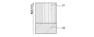
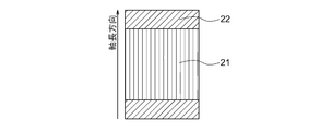
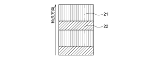
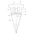
- FIG. 11 and FIG. 12 show shape diagrams when the tooth tip width is an electrical angle of 65 ° ( ⁇ 1) and when the tooth tip width is an electrical angle of 95 ° ( ⁇ 2).
- the cosine value of the 6f component of the teeth suction average value of the teeth tip width ⁇ 1 and the teeth tip width ⁇ 2 is 1: 2 and the phase is 180 ° opposite
- the teeth tip width ⁇ 1 and the teeth tip width ⁇ 2 When the ratio of the axial length of the teeth 4 is combined in the axial length direction at 2: 1, the 6f component of the average suction force value of the teeth 4 becomes small.
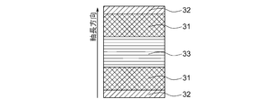
- the portion 21 having the teeth tip width ⁇ 1 and the portion 22 having the teeth tip width ⁇ 2 may be divided at one place in the axial length direction. As shown in FIG. 2, they may be combined at two or more locations. That is, when considering the entire axial length, it is sufficient that the axial length ratio is such that the 6f component of the suction force average value of the teeth 4 is minimized.
- the optimum skew angle was examined at 72 degrees or more. However, since a dimensional tolerance occurs at the time of manufacture, a difference of ⁇ mechanical angle 0.2 degrees (electrical angle 2.4 degrees) occurs in the actual machine shape. May be. Further, the S1 / P-order changes F ⁇ 1 and F ⁇ 2 of the radial suction force correspond to positive and negative values, respectively.
- FIG. 16 is a shape diagram in which the tip width of the teeth is an electrical angle of 61 ° ( ⁇ 1) when the polar arc angle of the magnet is 128.1 °
- FIG. 17 is the width of the tips of the teeth when the polar arc angle of the magnet is 128.1 °.
- FIG. 18 is a shape diagram with a tooth tip width of an electrical angle of 100 ° when the polar arc angle of the magnet is 128.1 ° ( ⁇ 3).
- Embodiment 3 three types of teeth tip widths of ⁇ 1, ⁇ 2, and ⁇ 3 are used, and each portion is configured in the axial direction of the stator 1. Note that the width of the tip end of the teeth is ⁇ 1 ⁇ 2 ⁇ 3.
- the average value of the radial suction force generated in all the teeth 4 is H.
- the least common multiple of the number of poles and the number of slots is S1.
- the tooth tip widths at which the absolute values of the cosine and sine are minimum are ⁇ 1 and ⁇ 2, respectively.
- the smaller electrical angle is Amin
- the larger electrical angle is Amax.
- the teeth tip widths are ⁇ 1 ⁇ Amin and Amax ⁇ 3 with respect to the polar arc angle of each permanent magnet 13.
- a portion 31 having a teeth tip width ⁇ 1, a portion 32 having a teeth tip width ⁇ 2, and a portion 33 having a teeth tip width ⁇ 2 may be divided at two locations in the axial length direction. .
- H is the S1 / P order component of the average suction force value of all teeth 4.
- Gj is the S1 / P-order component of the suction force average value of all the teeth 4 at the j-th tooth tip width of the K types of portions having different tooth tip widths.
- Lj indicates the thickness of the jth tooth tip width of K types of portions having different tooth tip widths.
- the value obtained by combining the sine and cosine of the S1 / P order component of the average suction force of the teeth with the teeth tip width ⁇ 1, the teeth tip width ⁇ 2, and the teeth tip width ⁇ 3 is 1.5: 0.5: 1.
- the ratio of the axial lengths of the tooth tip width ⁇ 1, the teeth tip width ⁇ 2, and the teeth tip width ⁇ 3 is 1.5: 0.5: 1 and combined in the axial length direction. Then, the S1 / P-order component of the average suction force value of the teeth 4 becomes small.
- FIG. 22 shows that when the polar arc angle of the magnet is 128.1 ° in electrical angle and the tooth tip width is 61 ° electrical angle, the electrical angle is 69 °, the electrical angle is 100 °, and the electrical angle is 61 °.
- the angle 69 ° and the electrical angle 100 ° are combined, when the electrical angle 65 ° and the electrical angle 95 ° are combined, the S1 / P order component of the average suction force value of the teeth 4 when the electrical angle is 77 ° Indicates the size.
- the vertical axis normalizes the S1 / P order component of the average suction force value of each tooth 4 with a value of an electrical angle of 77 °.
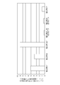
- the ratio of the lengths of the teeth 4 in the axial direction of the stator 1 is 65 °, 69 °, and 100 °. This is shown in the case of 1.5: 0.5: 1.
- the ratio of the lengths of the teeth 4 in the axial direction of the stator 1 is 2: 1 between the electrical angle of 65 ° and the electrical angle of 95 °. Show.
- the S1 / P order component when the electrical angle 61 °, the electrical angle 69 °, and the electrical angle 100 ° are combined is more than that when the electrical angle 65 ° and the electrical angle 95 ° are combined. To reduce.
- three types of teeth tip width portions are combined so that both the sine and cosine of the suction force of the teeth 4 are reduced, but more types of teeth tip width portions are combined.
- the above effects are achieved when three types of parts are combined.
- the stator 1 has a divided tooth structure in which each tooth 4 is divided in the circumferential direction, the tooth tip width can be set without being restricted by the arrangement and shape of the windings. Can be combined.
- Embodiment 4 FIG. Next, a fourth embodiment of the present invention will be described.
- the basic configuration of the rotating electrical machine of the fourth embodiment is the same as that shown in FIG.
- the rotor 11 is skewed by a plurality of stages in the axial direction.
- the skew angle is not less than 72 degrees and not more than 180 degrees when viewed over the entire axial length of the rotor 11.
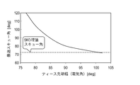
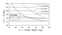
- FIG. 23 shows the arrangement of the rotor 11 so that the 6f component of the average attractive force of the teeth 4 is minimized when the polar arc angle ⁇ of the permanent magnet 13 of the rotating electrical machine of the fourth embodiment is 128.1 °. It is a graph which shows the relationship between 6f component of the attraction
- the cosine value of the 6f component of the average suction force value of the teeth 4 can be reduced to almost zero.
- the sine value has a minimum value with respect to the tooth tip width
- the amplitude has a minimum value in the vicinity of the tooth tip width of 88 °.
- FIG. 24 shows the relationship between the optimum skew angle and the tooth tip width in FIG. As shown in FIG. 24, as the tooth tip width increases, it gradually approaches the theoretical skew angle of 5f, which is 72 degrees. It can be seen that the optimum skew angle increases as the tooth tip width decreases.
- the skew angle shown in the present embodiment is an electrical angle representing the angle in the entire axial length direction.
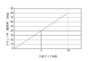
- the skew angle is 0 ° from 0 to a, and the skew angle is 40 ° from a to 2a (the straight line in FIG. 25).
- the skew angle per axial length 2a currently an electrical angle of 80 degrees
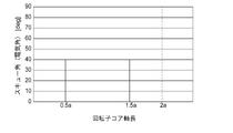
- the number of skew stages is equivalent even if the number of skew stages is three or more.
- the skew angle does not have to increase uniformly.
- the axial length when the skew angle is 0 ° is a, and the axial length when the skew angle is 40 ° is also a. Therefore, when the skew angle is smaller and larger, the whole is the same as FIG. Thus, the skew angle is expressed as an electrical angle of 80 degrees.
- FIG. 27 shows the optimum skew angle when the polar arc angle of the permanent magnet 13 is changed. Similarly to FIG. 25, it can be seen that the optimum skew angle is 72 degrees or more even when the polar arc angle is changed.
- the optimum skew angle is 72 degrees or more. By doing this, 6f of the suction force average value of the teeth 4 can be reduced.
- the teeth hook 5 is provided symmetrically with respect to one tooth 4 has been described.
- FIG. It may be asymmetric with respect to the center line in the width direction, and has the same effect.
- stator 1 stator, 2 stator cores, 3 core backs, 4 teeth, 6 slots, 11 rotors, 12 rotor cores, 13 permanent magnets.
Landscapes
- Engineering & Computer Science (AREA)
- Power Engineering (AREA)
- Iron Core Of Rotating Electric Machines (AREA)
- Permanent Magnet Type Synchronous Machine (AREA)
Abstract
L'invention concerne une machine dynamo-électrique dans laquelle des fentes sont ménagées entre les dents d'un noyau de stator. Le rapport du nombre de pôles et du nombre de fentes est de 2:3. La largeur de pointe de dent, qui est la dimension de largeur de la pointe des dents dans la direction circonférentielle du stator, se trouve dans une plage de l'angle électrique ±0,2° x P par rapport à une valeur qui satisfait β=-2,5α + 319,7 (0 < β ≤ 180) [degrés], où α est l'angle électrique de la largeur de pointe de dent, β est l'angle électrique de l'angle d'arc de pôle, qui est l'angle formé par deux lignes droites qui relient le centre de rotation du rotor aux coins sur le côté surface de rotor d'un aimant permanent, et P est le nombre de paires de pôles.
Priority Applications (4)
| Application Number | Priority Date | Filing Date | Title |
|---|---|---|---|
| CN201680083166.1A CN108781032B (zh) | 2016-03-10 | 2016-11-29 | 旋转电机 |
| DE112016006562.0T DE112016006562T5 (de) | 2016-03-10 | 2016-11-29 | Rotierende elektrische Maschine |
| JP2018504002A JP6452886B2 (ja) | 2016-03-10 | 2016-11-29 | 回転電機 |
| US16/072,005 US11171523B2 (en) | 2016-03-10 | 2016-11-29 | Rotary electric machine |
Applications Claiming Priority (2)
| Application Number | Priority Date | Filing Date | Title |
|---|---|---|---|
| JP2016-046857 | 2016-03-10 | ||
| JP2016046857 | 2016-03-10 |
Publications (1)
| Publication Number | Publication Date |
|---|---|
| WO2017154287A1 true WO2017154287A1 (fr) | 2017-09-14 |
Family
ID=59790267
Family Applications (1)
| Application Number | Title | Priority Date | Filing Date |
|---|---|---|---|
| PCT/JP2016/085402 Ceased WO2017154287A1 (fr) | 2016-03-10 | 2016-11-29 | Machine dynamo-électrique |
Country Status (5)
| Country | Link |
|---|---|
| US (1) | US11171523B2 (fr) |
| JP (1) | JP6452886B2 (fr) |
| CN (1) | CN108781032B (fr) |
| DE (1) | DE112016006562T5 (fr) |
| WO (1) | WO2017154287A1 (fr) |
Cited By (3)
| Publication number | Priority date | Publication date | Assignee | Title |
|---|---|---|---|---|
| CN116232003A (zh) * | 2022-12-09 | 2023-06-06 | 河北工业大学 | 一种双边非对称模块化永磁直线电机 |
| JP2023183954A (ja) * | 2022-06-17 | 2023-12-28 | 三菱電機株式会社 | 回転電機 |
| WO2024224546A1 (fr) * | 2023-04-27 | 2024-10-31 | 三菱電機株式会社 | Machine électrique tournante |
Families Citing this family (3)
| Publication number | Priority date | Publication date | Assignee | Title |
|---|---|---|---|---|
| US20220077733A1 (en) * | 2019-02-12 | 2022-03-10 | Mitsubishi Electric Corporation | Rotor for rotating electric machine and method of manufacturing the same |
| JP7258100B1 (ja) * | 2021-10-15 | 2023-04-14 | 三菱電機株式会社 | 回転電機 |
| CN119628264A (zh) * | 2023-09-13 | 2025-03-14 | 上海理想汽车科技有限公司 | 定子齿、电机定子、电机及车辆 |
Citations (2)
| Publication number | Priority date | Publication date | Assignee | Title |
|---|---|---|---|---|
| WO2008105049A1 (fr) * | 2007-02-26 | 2008-09-04 | Mitsubishi Electric Corporation | Moteur à aimant permanent, compresseur hermétique et moteur de ventilateur |
| JP2015096024A (ja) * | 2013-11-14 | 2015-05-18 | アスモ株式会社 | コア及びモータ |
Family Cites Families (5)
| Publication number | Priority date | Publication date | Assignee | Title |
|---|---|---|---|---|
| JP2002101628A (ja) * | 2000-09-22 | 2002-04-05 | Hitachi Ltd | 永久磁石式回転電機 |
| JP2002112472A (ja) | 2000-09-28 | 2002-04-12 | Matsushita Electric Ind Co Ltd | モータ及びそれを用いた圧縮機及びその製造方法 |
| JP2002136003A (ja) * | 2000-10-24 | 2002-05-10 | Mitsubishi Electric Corp | 回転電機の固定子 |
| JP4718580B2 (ja) * | 2008-05-22 | 2011-07-06 | 三菱電機株式会社 | 永久磁石型回転電機及び電動パワーステアリング装置 |
| DE112008003966T5 (de) * | 2008-07-31 | 2011-06-01 | Hewlett-Packard Development Co., L.P., Houston | Selektives Um-Abbilden einer Netzwerktopologie |
-
2016
- 2016-11-29 CN CN201680083166.1A patent/CN108781032B/zh active Active
- 2016-11-29 JP JP2018504002A patent/JP6452886B2/ja active Active
- 2016-11-29 US US16/072,005 patent/US11171523B2/en active Active
- 2016-11-29 DE DE112016006562.0T patent/DE112016006562T5/de active Pending
- 2016-11-29 WO PCT/JP2016/085402 patent/WO2017154287A1/fr not_active Ceased
Patent Citations (2)
| Publication number | Priority date | Publication date | Assignee | Title |
|---|---|---|---|---|
| WO2008105049A1 (fr) * | 2007-02-26 | 2008-09-04 | Mitsubishi Electric Corporation | Moteur à aimant permanent, compresseur hermétique et moteur de ventilateur |
| JP2015096024A (ja) * | 2013-11-14 | 2015-05-18 | アスモ株式会社 | コア及びモータ |
Cited By (3)
| Publication number | Priority date | Publication date | Assignee | Title |
|---|---|---|---|---|
| JP2023183954A (ja) * | 2022-06-17 | 2023-12-28 | 三菱電機株式会社 | 回転電機 |
| CN116232003A (zh) * | 2022-12-09 | 2023-06-06 | 河北工业大学 | 一种双边非对称模块化永磁直线电机 |
| WO2024224546A1 (fr) * | 2023-04-27 | 2024-10-31 | 三菱電機株式会社 | Machine électrique tournante |
Also Published As
| Publication number | Publication date |
|---|---|
| DE112016006562T5 (de) | 2018-11-15 |
| CN108781032A (zh) | 2018-11-09 |
| JP6452886B2 (ja) | 2019-01-16 |
| CN108781032B (zh) | 2020-07-14 |
| JPWO2017154287A1 (ja) | 2018-07-26 |
| US20190036387A1 (en) | 2019-01-31 |
| US11171523B2 (en) | 2021-11-09 |
Similar Documents
| Publication | Publication Date | Title |
|---|---|---|
| US7417346B2 (en) | Permanent magnet rotating electric machine | |
| US10644550B2 (en) | Rotor for rotating electric machine | |
| JP6452886B2 (ja) | 回転電機 | |
| JP5861394B2 (ja) | 電動回転機 | |
| CN102122852B (zh) | 电机 | |
| US8319386B2 (en) | Motor | |
| JP5857627B2 (ja) | 電動回転機 | |
| JP2013162556A (ja) | 電動回転機 | |
| JP2013106496A (ja) | 電動回転機 | |
| US20130106227A1 (en) | Electric rotating machine | |
| MX2013001030A (es) | Rotor para motor electrico. | |
| CN107453571B (zh) | 开关磁阻电机 | |
| CN101741158A (zh) | 具有偏置磁极间隔的永磁机 | |
| JP6550846B2 (ja) | 回転電機 | |
| JP2006340487A (ja) | ブラシレスモータ | |
| JP2013207857A (ja) | ブラシレスモータ | |
| JP2013132154A (ja) | 回転電機および回転電機のロータ | |
| JP7258100B1 (ja) | 回転電機 | |
| JP5491344B2 (ja) | モータ | |
| WO2014157049A1 (fr) | Générateur de puissance magnétique | |
| US20190260242A1 (en) | Rotary electric machine | |
| JP2013099170A (ja) | 電動回転機 | |
| JP2023156535A (ja) | 回転電機 |
Legal Events
| Date | Code | Title | Description |
|---|---|---|---|
| ENP | Entry into the national phase |
Ref document number: 2018504002 Country of ref document: JP Kind code of ref document: A |
|
| 121 | Ep: the epo has been informed by wipo that ep was designated in this application |
Ref document number: 16893611 Country of ref document: EP Kind code of ref document: A1 |
|
| 122 | Ep: pct application non-entry in european phase |
Ref document number: 16893611 Country of ref document: EP Kind code of ref document: A1 |