WO2017154445A1 - Structure isolée utilisant un matériau d'isolation thermique à vide et récipient isolé la comportant - Google Patents
Structure isolée utilisant un matériau d'isolation thermique à vide et récipient isolé la comportant Download PDFInfo
- Publication number
- WO2017154445A1 WO2017154445A1 PCT/JP2017/004480 JP2017004480W WO2017154445A1 WO 2017154445 A1 WO2017154445 A1 WO 2017154445A1 JP 2017004480 W JP2017004480 W JP 2017004480W WO 2017154445 A1 WO2017154445 A1 WO 2017154445A1
- Authority
- WO
- WIPO (PCT)
- Prior art keywords
- heat insulating
- adhesive
- vacuum heat
- insulating material
- vacuum
- Prior art date
- Legal status (The legal status is an assumption and is not a legal conclusion. Google has not performed a legal analysis and makes no representation as to the accuracy of the status listed.)
- Ceased
Links
Images





Classifications
-
- F—MECHANICAL ENGINEERING; LIGHTING; HEATING; WEAPONS; BLASTING
- F16—ENGINEERING ELEMENTS AND UNITS; GENERAL MEASURES FOR PRODUCING AND MAINTAINING EFFECTIVE FUNCTIONING OF MACHINES OR INSTALLATIONS; THERMAL INSULATION IN GENERAL
- F16L—PIPES; JOINTS OR FITTINGS FOR PIPES; SUPPORTS FOR PIPES, CABLES OR PROTECTIVE TUBING; MEANS FOR THERMAL INSULATION IN GENERAL
- F16L59/00—Thermal insulation in general
- F16L59/06—Arrangements using an air layer or vacuum
- F16L59/065—Arrangements using an air layer or vacuum using vacuum
-
- B—PERFORMING OPERATIONS; TRANSPORTING
- B32—LAYERED PRODUCTS
- B32B—LAYERED PRODUCTS, i.e. PRODUCTS BUILT-UP OF STRATA OF FLAT OR NON-FLAT, e.g. CELLULAR OR HONEYCOMB, FORM
- B32B7/00—Layered products characterised by the relation between layers; Layered products characterised by the relative orientation of features between layers, or by the relative values of a measurable parameter between layers, i.e. products comprising layers having different physical, chemical or physicochemical properties; Layered products characterised by the interconnection of layers
- B32B7/04—Interconnection of layers
Definitions
- the present disclosure relates to a heat insulating structure using a vacuum heat insulating material having a configuration in which a core material is sealed in a vacuum sealed state inside a jacket material, and a heat insulating container having the heat insulating structure.
- the vacuum heat insulating material has a structure in which a core material is sealed under reduced pressure and sealed inside a jacket material (outer packaging material) having gas barrier properties.
- a jacket material a laminated film in which functional layers such as a heat sealing layer, a surface protective layer, and a gas barrier layer are laminated is generally used.
- Vacuum insulation is widely used for consumer products such as electrical appliances and housing materials, but in recent years the use of industrial products is also being considered.
- Industrial products include, for example, ships such as gas tankers, insulated containers for holding low-temperature fluids such as LNG (liquefied natural gas) tanks, and automobiles (for example, for heat insulation of vehicle bodies, engines, transmissions, batteries, etc.) Is mentioned.
- LNG liquefied natural gas
- Patent Document 1 a gas barrier layer of a jacket material is formed as a vapor deposition layer of metal, metal oxide, silica, or the like, and an acrylic resin layer is coated on the vapor deposition layer.
- a vacuum insulation is disclosed.
- home appliances such as electric water heaters, that is, consumer products, are exemplified as typical applications.
- heat insulation structures using vacuum heat insulating materials Compared with consumer products, industrial products tend to have stricter characteristics required for heat insulation performance of heat insulating structures using vacuum heat insulating materials.
- a ship such as the gas tanker described above holds a low-temperature fluid that is significantly lower than room temperature for a long period of time. For this reason, the heat insulation structure using a vacuum heat insulating material will be used for a long time in a low-temperature environment.
- heat insulation structures using vacuum insulation materials are used not only in low-temperature environments but also in environments where very large temperature differences occur, as ships may be exposed to temperatures higher than room temperature during ship maintenance. It will be.
- long-term use for example, several decades
- long-term reliability is also required for heat-insulating structures using vacuum heat insulating materials.
- This disclosure further optimizes the reliability of heat insulation performance so that it can be applied to industrial products in a heat insulating structure using a vacuum heat insulating material.
- the heat insulating structure according to the present disclosure is a heat insulating structure that is used in an environment exposed to a low temperature of ⁇ 40 ° C. or lower and includes at least a vacuum heat insulating material and other members.
- the vacuum heat insulating material includes a jacket material and a core material sealed in a vacuum-sealed state inside the jacket material.
- the vacuum heat insulating material is configured to be adjacent to another member or another vacuum heat insulating material in the wet surface region through an elastic material.
- a wet surface region is formed on the outer surface of the vacuum heat insulating material constituting the heat insulating structure, and the vacuum heat insulating material and other members are in a state in which an elastic material is interposed in the wet surface region.
- the vacuum heat insulating materials are adjacent to each other with the elastic material interposed between the wetted surface regions.
- the heat insulation structure When the heat insulation structure is used in an environment where it is exposed to a low temperature of ⁇ 40 ° C. or lower, a large temperature stress may occur due to a large temperature difference from room temperature. Can alleviate the effects.
- the outer surface of the vacuum heat insulating material to which the elastic material is in close contact is a wet surface region, it is possible to ensure good adhesion between the elastic material and the vacuum heat insulating material. As a result, in the heat insulating structure using the vacuum heat insulating material, the reliability of the heat insulating performance can be further optimized so as to be applicable to industrial products.
- the present disclosure includes a heat insulating container including the heat insulating structure having the above-described configuration.
- the reliability of the heat insulation performance can be further optimized so that the heat insulation structure using the vacuum heat insulating material can be applied to industrial products.
- FIG. 1 is a typical sectional view showing an example of composition of a vacuum heat insulating material used for a heat insulation structure concerning a 1st embodiment of this indication.
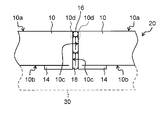
- FIG. 2 is a schematic partial cross-sectional view illustrating an example of a configuration of a heat insulating structure according to the present disclosure using the vacuum heat insulating material illustrated in FIG. 1.
- FIG. 3A is a schematic plan view showing an example of application of an adhesive to the back surface of the vacuum heat insulating material in the heat insulating structure shown in FIG. 2.
- FIG. 3B is a schematic plan view showing another example of application of the adhesive to the back surface of the vacuum heat insulating material in the heat insulating structure shown in FIG. 2.
- FIG. 3A is a schematic plan view showing an example of application of an adhesive to the back surface of the vacuum heat insulating material in the heat insulating structure shown in FIG. 2.
- FIG. 3B is a schematic plan view showing another example of application of the adhesive to the back surface of the vacuum heat insulating
- FIG. 4A is a schematic partial side view illustrating another example of the heat insulating structure according to the present disclosure using the vacuum heat insulating material illustrated in FIG. 1.
- FIG. 4B is a schematic partial side view showing still another example of the heat insulating structure according to the present disclosure using the vacuum heat insulating material shown in FIG. 1.
- FIG. 5A illustrates a schematic configuration of a spherical independent tank type LNG transport tanker including a spherical tank, which is an example of a heat insulating container according to the second embodiment of the present disclosure, to which the heat insulating structure according to the present disclosure is applied. It is a schematic diagram shown.
- FIG. 1 illustrates a schematic configuration of a spherical independent tank type LNG transport tanker including a spherical tank, which is an example of a heat insulating container according to the second embodiment of the present disclosure, to which the heat insulating structure according to the present disclosure is applied. It is a schematic diagram shown.
- FIG. 1 illustrates
- FIG. 5B is a schematic diagram showing a schematic configuration of a spherical tank corresponding to a cross section taken along the line 5B-5B in FIG. 5A.
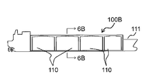
- FIG. 6A is a schematic diagram illustrating a schematic configuration of a membrane-type LNG transport tanker including an inboard tank, which is a heat insulating container according to a third embodiment of the present disclosure, to which the heat insulating structure according to the present disclosure is applied.
- It is. 6B is a schematic diagram showing a schematic configuration of the inboard tank corresponding to the cross section taken along the arrow 6B-6B in FIG. 6A.
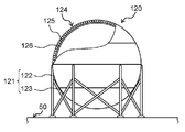
- FIG. 7 is a schematic partial cross-sectional view illustrating a typical configuration of an above-ground LNG tank, which is a heat insulating container according to the fourth embodiment of the present disclosure, to which the heat insulating structure according to the present disclosure is applied.
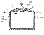
- FIG. 8 is a schematic cross-sectional view showing another example of a typical configuration of an underground LNG tank, which is a heat insulating container according to the fourth embodiment of the present disclosure, to which a heat insulating structure according to the present disclosure is applied.
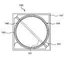
- FIG. FIG. 9 is a schematic cross-sectional view showing a typical configuration of a hydrogen tank, which is a heat insulating container according to the fifth embodiment of the present disclosure, to which the heat insulating structure according to the present disclosure is applied.
- the heat insulating structure according to the present disclosure is used in an environment exposed to a low temperature of ⁇ 40 ° C. or lower, and includes at least a vacuum heat insulating material and other members.
- the vacuum heat insulating material includes a jacket material and a core material sealed in a vacuum-sealed state inside the jacket material. Wet surface region where the outer surface of the surface of the jacket material is the outer surface of the vacuum heat insulating material, and the outer surface is given a surface state that exhibits greater wettability than the inherent wettability of the surface. Is included.
- the vacuum heat insulating material is configured to be adjacent to another member or the other vacuum heat insulating material in the wet surface region through the elastic material.
- the wet surface region is formed on the outer surface of the vacuum heat insulating material constituting the heat insulating structure, and the vacuum heat insulating material and the other member are in a state where the elastic material is interposed in the wet surface region. Adjacent or vacuum heat insulating materials are adjacent to each other with the elastic material interposed between the wetted surface regions.
- the outer surface of the vacuum heat insulating material to which the elastic material is in close contact is a wet surface region, it is possible to ensure good adhesion between the elastic material and the vacuum heat insulating material.
- the reliability of the heat insulating performance can be further optimized so as to be applicable to industrial products.
- the wet surface area may be configured by a surface treatment or a resin coat on the outer surface.
- the surface of the outer jacket material is further surface-treated or resin-coated to provide a wet surface area that exhibits wettability greater than the inherent wettability of the outer jacket material surface. It can be suitably realized.
- the wet surface area may be given to an area on the outer surface that is at least the back surface of the vacuum heat insulating material.
- the vacuum heat insulating material may be configured to be bonded to another member by partially applying an adhesive as an elastic material on the back surface.
- the elastic material is further an adhesive, and this adhesive is partially applied to the back surface of the vacuum heat insulating material. Therefore, the applied adhesive can be held well on the back surface of the vacuum heat insulating material, and if the adhesive is not applied to the entire surface on the back surface, the effect of shrinkage due to large thermal stress is exerted. It can be relaxed well.
- the adhesive may include a first adhesive having tackiness at normal temperature and a second adhesive having higher tackiness than the first adhesive at low temperature. And the structure by which the 1st adhesive agent and the 2nd adhesive agent were apply
- the adhesive since the first adhesive and the second adhesive are used in combination as the elastic material, the adhesive has a better adhesion due to the tackiness of the first adhesive at room temperature and in the temperature range around it. A state can be realized. In addition, at a low temperature and in a temperature range in the vicinity thereof, a good adhesion state can be realized due to the tackiness of the second adhesive. Therefore, since two types of adhesives can exhibit favorable adhesiveness in different temperature ranges, a good bonding state of the vacuum heat insulating material can be stably realized in a wide temperature range.
- the first adhesive and the second adhesive may be alternately applied to the back surface.
- the first adhesive and the second adhesive are applied such that the application area of the first adhesive is wider than the application area of the second adhesive on the back surface. It may be a configuration.
- the first adhesive may be a hot melt adhesive
- the second adhesive may be a reactive adhesive
- a good bonding state can be more stably realized in a wide temperature range on the back surface of the vacuum heat insulating material. Can do.
- the adhesive may have a peel strength of 25N width and 13N or more.
- the vacuum heat insulating material can be bonded to the surface of another member even better.
- the vacuum heat insulating material may include a plurality of vacuum heat insulating materials, and the wet surface area may be applied to a region that is at least an outer side surface of the vacuum heat insulating material among the outer surfaces. .
- positioned adjacently among several vacuum heat insulating materials may be sufficient.
- the filling material is further interposed at the abutting portion between the side surfaces of the plurality of vacuum heat insulating materials, and the side surface of the vacuum heat insulating material in close contact with the filling material is a wet surface region. Therefore, when the filling material adheres well to the side surface of the vacuum heat insulating material, high sealing performance of the heat insulating layer made of the vacuum heat insulating material can be realized well. Moreover, the influence of shrinkage derived from large thermal stress can be mitigated satisfactorily by the filling material.
- the filling material may be made of a thermosetting resin elastomer material.
- the filling material is made of an elastomer material such as silicone rubber or soft urethane, the influence of shrinkage due to a large thermal stress can be further alleviated.
- the surface treatment may be corona treatment, ozone treatment, or plasma treatment
- the resin coat may be a urethane coat or a silicon coat.
- the wet surface region can be favorably formed in at least the region serving as the outer surface of the surface of the jacket material.
- the present disclosure includes a heat insulating container including the heat insulating structure having the above-described configuration.
- the heat insulating performance reliability is further optimized so that the heat insulating structure or the heat insulating container can be applied to industrial products. be able to.
- a vacuum heat insulating material 10 is enclosed in an outer cover material (outer packaging material) 11 and a vacuum sealed state (substantially vacuum state) inside the outer cover material 11.
- a core material 12 and an adsorbent 13 enclosed in the jacket material 11 together with the core material 12 are provided.
- the jacket material 11 is a bag-shaped member having gas barrier properties.
- the sealing part 14 which is the surrounding sealed part is a state in which the core material 12 does not exist inside and the laminated sheets are in contact with each other, and extends from the main body of the vacuum heat insulating material 10 toward the outer periphery. It is formed in a fin shape.
- the specific configuration of the laminated sheet is not particularly limited, and examples thereof include a configuration in which three layers of a surface protective layer, a gas barrier layer, and a heat welding layer are laminated in this order.
- the surface protective layer is a resin layer for protecting the outer surface of the vacuum heat insulating material 10.
- a known resin film such as a nylon film, a polyethylene terephthalate film, or a polypropylene film is used, but is not particularly limited thereto.
- the surface protective layer may be composed of only one type of film, or may be composed of a plurality of laminated films.
- the gas barrier layer is a layer for preventing outside air from entering the inside of the vacuum heat insulating material 10, and a known film having gas barrier properties can be suitably used.
- a known film having gas barrier properties include a metal foil such as an aluminum foil, a copper foil, or a stainless steel foil, a vapor-deposited film in which a metal or a metal oxide is vapor-deposited on a resin film serving as a substrate, or the vapor-deposited film.
- the surface of the film may be a film having a further known coating treatment, but is not particularly limited thereto.
- Examples of the base material used for the vapor deposition film include a polyethylene terephthalate film or an ethylene-vinyl alcohol copolymer film, and examples of the metal or metal oxide include aluminum, copper, alumina, or silica. However, it is not particularly limited to these.
- the heat welding layer is a layer for laminating the laminated sheets facing each other, and also functions as a layer for protecting the surface of the gas barrier layer. That is, one surface (outer surface) of the gas barrier layer is protected by the surface protective layer, while the other surface (inner surface) is protected by the heat welding layer. Since the core material 12 and the adsorbent 13 are enclosed inside the vacuum heat insulating material 10, the influence on the gas barrier layer by the objects inside these is prevented or suppressed by the heat welding layer.
- the heat welding layer include a film made of a thermoplastic resin such as low density polyethylene, but are not particularly limited thereto.
- the laminated sheet may include layers other than the surface protective layer, the gas barrier layer, and the heat welding layer.
- the gas barrier layer and the heat-welded layer may be composed of only one type of film as in the case of the surface protective layer, or may be composed of a plurality of films laminated. That is, the laminated sheet used as the covering material 11 has one surface of the pair of surfaces (inner surface and outer surface) as a heat-welded layer, and a gas barrier layer in the multilayer structure.
- the specific configuration is not particularly limited as long as the condition that any layer of the multilayer structure has gas barrier properties is satisfied.
- jacket material 11 a known configuration other than the laminated sheet can be adopted as long as it can exhibit gas barrier properties.
- the core material 12 is not particularly limited as long as it has a heat insulating property. Specific examples include known materials such as fiber materials and foam materials.
- inorganic fibers are used as the core material 12.
- the inorganic fiber may be a fiber made of an inorganic material, and specific examples include glass fiber, ceramic fiber, slag wool fiber, rock wool fiber, and the like.
- the core material 12 may be formed into a plate shape and used, in addition to these inorganic fibers, at least one of a known binder material and powder may be included. These materials contribute to the improvement of physical properties such as strength, uniformity and rigidity of the core material 12.
- the specific shape and the like of the core material 12 are not particularly limited, but representatively, examples include those obtained by forming inorganic fibers such as glass fibers into a board shape. Specifically, for example, glass fibers are laminated in a flat plate shape, and this laminate is placed in a jig and heated in a pressurized state with a pressure press or the like so that the density and thickness are within a predetermined range.
- the core material 12 is obtained by molding.
- the pressurizing condition and heating condition of the glass fiber are not particularly limited, and known conditions in the field of manufacturing the vacuum heat insulating material 10 can be suitably used.
- the adsorbent 13 is formed from the residual gas (including water vapor) released from the fine voids of the core material 12 after the core material 12 is sealed under reduced pressure inside the outer cover material 11, the sealing portion 14, and the like. Adsorbs and removes outside air (including water vapor) that slightly enters.
- the specific kind of the adsorbent 13 is not particularly limited, and a material selected from known materials including zeolite, calcium oxide, silica gel, and the like can be suitably used.
- the vacuum heat insulating material 10 should just be provided with the jacket material 11 and the core material 12, and may be provided with members other than the jacket material 11, the core material 12, and the adsorbent 13 mentioned above.
- the specific manufacturing method of the vacuum heat insulating material 10 is not particularly limited, and a known manufacturing method can be suitably used.
- the two envelope materials 11 are overlapped, and the peripheral portion is thermally welded so as to form an opening, thereby obtaining a bag body of the envelope material 11.
- the core material 12 and the adsorbent 13 are inserted into the bag body of the jacket material 11 from the opening, and the pressure is reduced in a decompression facility such as a decompression chamber.
- a decompression facility such as a decompression chamber.
- the inside of the bag body of the covering material 11 is sufficiently decompressed from the opening, and a substantially vacuum state is obtained.
- the vacuum insulating material 10 is obtained by hermetically sealing the opening by heat welding.
- the bag body of the jacket material 11 is not limited to the configuration in which the periphery of the two jacket materials 11 is thermally welded.
- a bag of the covering material 11 having an opening can be obtained by bending one covering material 11 in half and thermally welding both side edges.
- a bag body of the covering material 11 having an opening can be obtained by molding the covering material 11 into a cylindrical shape and sealing one opening.
- the heat insulating structure 20 includes at least the vacuum heat insulating material 10 and the other member 30, and is used in an environment exposed to a low temperature of ⁇ 40 ° C. or lower.
- a low temperature environment for example, an LNG tanker for transporting liquefied natural gas (LNG), which will be described later in the second embodiment or the third embodiment, will be described. Can be mentioned.
- LNG liquefied natural gas
- LNG is usually a low-temperature fluid of about ⁇ 162 ° C.
- the LNG tank that holds the LNG is provided with a heat insulating structure in order to prevent heat from entering the inside.
- the period during which the LNG tanker transports LNG is, for example, about four weeks. During this period, the outer surface of the heat insulating structure is at a temperature of about -130 ° C.
- the LNG tanker after transporting LNG does not exhaust the LNG from the LNG tank to empty it, but suppresses the temperature change by leaving a part of the LNG. Therefore, when the LNG tanker is in service, the temperature of the outer surface of the heat insulation structure is as low as about ⁇ 130 ° C.
- LNG tankers receive maintenance at the maintenance dock once every few years.
- the LNG tank may be exposed to a high temperature exceeding normal temperature.
- the outer surface of the heat insulating structure may be about + 80 ° C. Therefore, it is necessary to assume that the thermal insulation structure of the LNG tank is used with a temperature difference of ⁇ 130 ° C. to + 80 ° C. (temperature difference of ⁇ 210 ° C.).
- the heat insulating structure When a large temperature difference of ⁇ 210 ° C. occurs in the heat insulating structure, a large thermal stress is generated according to this temperature difference. Further, a ship such as an LNG tanker can be assumed to be used for a long period of several decades, for example. Therefore, the heat insulating structure is required to be able to cope with a large thermal stress and to realize high reliability over a long period of time even when such a thermal stress occurs.
- the wettability is imparted to at least a part of the surface of the covering material 11 that is the outer surface of the vacuum heat insulating material 10 and the wettability is set via an elastic material.
- the other member 30 or the other vacuum heat insulating material 10 is made to adjoin to the surface to which is given. Thereby, a big thermal stress can be relieved with an elastic material.
- the outer surface of the vacuum heat insulating material 10 to which the elastic material is in close contact has high wettability, good adhesion can be ensured between the elastic material and the vacuum heat insulating material 10.
- the reliability of the heat insulating performance can be further optimized.
- the great wettability refers to “wetability greater than the inherent wettability of the outer cover material 11”.
- the surface region of the outer cover material 11 to which such a surface state exhibiting high wettability is applied is referred to as a “wet surface region”.
- the wetted surface region only needs to be formed on the surface that is the outer surface of the vacuum heat insulating material 10 among the surfaces of the jacket material 11, that is, the “outer surface”.
- the vacuum heat insulating material 10 is in a state in which the sealing portion 14 is bent along one outer surface, and the other adhesive member 15 is an elastic material. Affixed to the member 30.
- the adhesive 15 that is an elastic material is interposed between the vacuum heat insulating material 10 and the other member 30.
- the outer surface facing the other member 30 in the vacuum heat insulating material 10 is referred to as “rear surface 10b”
- the outer surface not facing the other member 30 is referred to as “front surface 10a”
- the front surface 10a and A peripheral outer surface other than the back surface 10b is referred to as a “side surface 10c”.
- the wet surface region may be formed at least on the outer surface of the jacket material 11 that becomes the back surface 10 b.
- region may be formed also in the outer surface used as each outer surface (at least one of the front surface 10a and the side surface 10c) other than the back surface 10b. Further, the wet surface region may be formed over the entire outer surface serving as the back surface 10b (other outer surface as necessary) or may be partially formed.
- the wet surface region may be partially applied (formed) to the outer surface serving as the back surface 10b. it can.
- the wet surface region is also applied to the outer surface of the covering material 11 serving as the outer surface of the sealing part 14. Can be formed.
- the wet surface region may be a region showing a surface state having wettability larger than the inherent wettability of the outer cover material 11, and a method for realizing such a surface state is not particularly limited.
- a surface treatment or a resin coat on the outer surface of the jacket material 11 can be given.
- Specific surface treatments include, for example, corona treatment, ozone treatment, or plasma treatment, but are not particularly limited thereto.
- Specific examples of the resin coat include a urethane coat and a silicon coat, but are not particularly limited thereto.
- the specific type of the surface treatment or the resin coat can be appropriately selected according to the type, configuration, material, and the like of the sheet material (laminated sheet or the like) used as the covering material 11.
- the method for evaluating the wet surface area that is, the method for evaluating that the wettability greater than the surface specific wettability of the covering material 11 is not particularly limited, but in the present embodiment, in JIS K6768 Evaluation is performed by the prescribed determination method using a wet reagent or the dyne pen method.
- the vacuum heat insulating material 10 is bonded to the outer surface of another member 30 by partially applying the adhesive 15 as an elastic material to the back surface 10 b. Yes. Since the wet surface region is formed on the outer surface serving as the back surface 10b, the applied adhesive 15 can be favorably held on the back surface 10b of the vacuum heat insulating material 10. Further, since the adhesive 15 is not applied to the entire back surface 10b, it is possible to satisfactorily mitigate the influence of shrinkage caused by a large thermal stress.
- the specific type of the adhesive 15 as the elastic material is not particularly limited, such as the type or configuration of the vacuum heat insulating material 10, the type or configuration of the jacket material 11, or the use conditions or applications of the heat insulating structure 20. It can select suitably according to various conditions.
- the first adhesive 151 and the second adhesive 152 are used in combination.
- the first adhesive 151 and the second adhesive 152 are partially applied to the back surface 10b (applied to different parts).
- the first adhesive 151 is not particularly limited as long as it has tackiness (or adhesiveness) at room temperature. Moreover, it is preferable in the 1st adhesive agent 151 being what can exhibit initial stage adhesiveness (tack property). Thereby, when constructing the heat insulating structure 20, the vacuum heat insulating material 10 can be bonded to a desired position with respect to the other members 30 without using a positioning member or the like.
- a hot melt adhesive can be cited.
- the hot melt adhesive is composed mainly of a material that is solid or semi-solid at normal temperature and liquid at high temperature.
- the hot melt adhesive basically does not contain a solvent or the like. It is heated and melted to be liquefied and then applied and solidified by cooling to exhibit an adhesive action. Therefore, good adhesiveness can be exhibited at room temperature and the surrounding temperature region.
- the specific hot melt adhesive is not particularly limited, but is typically an ethylene vinyl acetate (EVA) adhesive, a polyamide (PA) adhesive, a polypropylene (PP) adhesive, or a rubber adhesive. Etc. Moreover, these adhesives can also be used by combining them appropriately and blending at a predetermined ratio.
- EVA ethylene vinyl acetate
- PA polyamide
- PP polypropylene
- Etc a rubber adhesive.
- these adhesives can also be used by combining them appropriately and blending at a predetermined ratio.
- the second adhesive 152 may be any adhesive as long as it has a tackiness (or adhesiveness) higher than that of the first adhesive 151 at a low temperature of ⁇ 40 ° C. or lower.
- a typical example is a reactive adhesive. it can.
- the reactive adhesive may be a one-pack type or a two-pack type. Specific reactive adhesives are not particularly limited, and examples thereof include urethane adhesives, epoxy adhesives, and nylon adhesives.
- the reactive adhesive has a low elastic modulus at a high temperature (higher than room temperature) temperature range, but tends to have a high elastic modulus at a low temperature (lower than normal temperature). Since the material exhibiting adhesiveness has high cohesive force and elasticity, the reactive adhesive can exhibit excellent adhesiveness even at a low temperature of ⁇ 40 ° C. or lower.
- the hot melt adhesive can exhibit good tackiness at and around normal temperature, but cannot exhibit sufficient tackiness at a low temperature of ⁇ 40 ° C. or lower.
- the first adhesive 151 and the second adhesive 152 are used in combination as the elastic material. Thereby, in normal temperature and the temperature range of the vicinity, a favorable bonding state is realizable by the adhesiveness (or adhesiveness) of the 1st adhesive agent 151. FIG. Further, in a low temperature of ⁇ 40 ° C. or lower and a temperature range in the vicinity thereof, a good bonding state can be realized due to the adhesiveness (or adhesiveness) of the second adhesive 152.
- a reactive adhesive is preferably used as the second adhesive 152, but the adhesive strength of the reactive adhesive gradually increases with time. Therefore, when the heat insulating structure 20 is constructed, the adhesive strength is low in the initial state in which the vacuum heat insulating material 10 is attached to another member 30 at room temperature.
- the first adhesive 151 is sticky (or adhesive) at room temperature, the first adhesive 151 can be bonded even at the initial stage where the adhesive strength of the second adhesive 152 is low. Good pasting is possible depending on the strength.
- the first adhesive 151 for example, a hot melt adhesive is preferably used.
- the hot melt adhesive can achieve high adhesive strength in the vicinity of normal temperature, it is normal temperature in a high temperature range. In some cases, sufficient adhesive strength cannot be exhibited in the vicinity of the temperature range.
- good peel strength is measured in a temperature range of ⁇ 20 ° C. to + 40 ° C., including a general normal temperature range (20 ° C. ⁇ 15 ° C.), but + 50 ° C. to + 60 ° C. When the temperature is higher than 1, the peel strength is lowered.
- the reactive adhesive although the adhesive strength is low in the initial state, a good peel strength is measured even when the temperature exceeds + 50 ° C. to + 60 ° C. after a sufficient time has passed. Therefore, by using the first adhesive 151 and the second adhesive 152 in combination, good adhesive strength can be realized in a wide temperature range.
- the method for evaluating the adhesive strength of the adhesive 15 is not particularly limited, but as described above, it may be evaluated by the peel strength. Specifically, it can be evaluated by, for example, a 180 ° peel test defined in JIS Z0237 or JIS K6854-2. In the present embodiment, the peeling rate at the 180 ° peeling test may be changed from the conditions defined in JIS, for example, a peeling rate of 300 mm / min may be adopted.
- the peel strength of the adhesive 15 is not particularly limited, but basically, it may be 13 N or more with a width of 25 mm. If the lower limit value of the peel strength of the adhesive 15 is the above value, the vacuum heat insulating material 10 can be satisfactorily bonded to the outer surface of the other member 30.
- the method of applying the adhesive 15 to the back surface 10b of the vacuum heat insulating material 10 is not particularly limited, but when the first adhesive 151 and the second adhesive 152 are used in combination as the adhesive 15, for example, in FIG. 3A or FIG. 3B As shown, a configuration in which the first adhesive 151 and the second adhesive 152 are alternately applied to the back surface 10b in a certain direction can be exemplified.
- the first adhesive 151 and the second adhesive 152 are alternately applied in a straight line, but for convenience of explanation, the first adhesive 151 is illustrated by a bold line, and the second adhesive 152 Is illustrated by a thick white line.
- the application area of the first adhesive 151 is wider than the application area of the second adhesive 152.
- the first adhesive 151 is applied as a coil-shaped drawing
- the second adhesive 152 is applied linearly as in FIG. 3A (in FIG. 3B).
- the second adhesive 152 is indicated by a thick white line).
- FIG. 4A and 4B show a state in which the end faces (side surfaces 10c) of the respective vacuum heat insulating materials 10 are abutted with each other when a plurality of vacuum heat insulating materials 10 are arranged adjacent to each other.
- a gap is formed between the joints of the vacuum heat insulating materials 10, that is, between the side surfaces 10 c facing each other.
- a large portion of the gap is filled with, for example, a filling heat insulating material 18, and the outside of the gap is filled with a silicone rubber filling material 16 (see FIG. 4A) or a soft urethane filling material 17 (FIG. 4B) as an elastic material. Is filled).
- the wet surface region is the region that becomes the side surface 10 c on the outer surface of the jacket material 11 at least on the outer side (front side 10 a side) of the vacuum heat insulating material 10,
- FIG. 4A and FIG. 4B what is necessary is just to form in the area
- the other member 30 is illustrated with the broken line for convenience of explanation, and the adhesive agent 15 is not illustrated.
- the wet surface region may be provided not only on the outer side surface 10d but also on the entire side surface 10c.
- the filling materials 16 and 17 are present at the abutting portions between the side surfaces 10c of the plurality of vacuum heat insulating materials 10, and the wet surface region is formed at least on the outer side surface 10d, the filling materials 16 and 17 are provided. 17 can adhere to the side surface 10c of the vacuum heat insulating material 10 satisfactorily. As a result, it is possible to satisfactorily realize the hermeticity of the heat insulating layer composed of the vacuum heat insulating material 10. Moreover, even if shrinkage due to a large thermal stress occurs, it can be satisfactorily mitigated by the filling materials 16 and 17 interposed in the joints (adjacent part, connecting part) between the plurality of vacuum heat insulating materials 10.
- the filling materials 16 and 17 should just be comprised as a linear member so that the clearance gap between the vacuum heat insulating materials 10 can be filled.
- the specific configuration of the filling material 16 is not particularly limited, and may be made of an elastic material in the same manner as the adhesive 15 described above.
- the linear material (filling material 16) made of silicone rubber or the linear material (filling material 17) made of soft urethane is exemplified. What is necessary is just to be comprised with the thermoplastic resin elastomer material like silicone rubber or soft urethane. If such a thermoplastic elastomer material is used, the influence of shrinkage derived from a large thermal stress can be further alleviated at the joint (adjacent part, connection part) between the vacuum heat insulating materials 10.
- heat insulating materials other than the vacuum heat insulating material 10 can be mentioned.
- heat insulating materials for example, a foamed resin heat insulating material such as styrene foam (polystyrene foam), polyurethane foam, or phenol foam, or an inorganic heat insulating material such as glass wool or pearlite filled in a heat insulating frame.
- styrene foam polystyrene foam
- polyurethane foam polyurethane foam
- phenol foam or an inorganic heat insulating material such as glass wool or pearlite filled in a heat insulating frame.
- an inorganic heat insulating material such as glass wool or pearlite filled in a heat insulating frame.
- the other heat insulating material may be comprised as a heat insulation panel.
- a wet surface region is formed on the outer surface of the vacuum heat insulating material 10 constituting the heat insulating structure 20, and the vacuum heat insulating material 10 and the other members 30 are wet surfaces.
- the region is adjacent to the region through the elastic material, and the vacuum heat insulating materials 10 are also adjacent to each other between the wet surface regions through the elastic material.
- the heat insulating structure 20 When the heat insulating structure 20 is used in an environment exposed to a low temperature of ⁇ 40 ° C. or less, a large temperature stress may occur due to a large temperature difference from room temperature, but due to the presence of an elastic material, The influence of thermal stress can be mitigated.
- the outer surface of the vacuum heat insulating material 10 to which the elastic material is in close contact is a wet surface region, good adhesion between the elastic material and the vacuum heat insulating material 10 can be ensured.
- the reliability of the heat insulating performance can be further optimized so as to be applicable to industrial products.
- the LNG transport tanker 100A in the present embodiment is a tank independent tank type tanker, and includes a plurality of spherical tanks 101 (five in FIG. 5A).
- the plurality of spherical tanks 101 are arranged in a line along the longitudinal direction of the hull 102.
- each spherical tank 101 includes a container main body 104, and the inside of the container main body 104 is an internal space (fluid holding space) for storing (or holding) LNG. Further, most of the spherical tank 101 is externally supported by the hull 102, and the upper part thereof is covered by the cover 103.
- the container body 104 includes a container housing 106 and a heat insulating structure 105 that insulates the outer surface of the container housing 106.
- the container housing 106 is configured to hold a low-temperature substance stored at a temperature lower than normal temperature, such as LNG, and is made of a metal such as a stainless steel material or an aluminum alloy. Since the temperature of LNG is normally ⁇ 162 ° C., a specific container housing 106 may be made of an aluminum alloy having a thickness of about 50 mm. Further, the container housing 106 may be made of stainless steel having a thickness of about 5 mm.
- the heat insulation structure 105 may be configured to include the heat insulation structure 20 described above.
- a typical configuration example of the heat insulating structure 105 a multilayer structure in which a plurality of heat insulating layers are arranged outside the container housing 106 can be given.
- the vacuum heat insulating material 10 mentioned above is used for at least one layer among these heat insulating layers, and this vacuum heat insulating material 10 should just be bonded to the other heat insulating material which is the other member 30.
- the heat insulating structure 20 in which the vacuum heat insulating material 10 is bonded to another heat insulating material is configured as a “heat insulating panel”, but the configuration of the heat insulating structure 20 is not limited thereto. If the heat insulation layer is composed of a square heat insulation panel, the square heat insulation panels are arranged and fixed in units of several thousand sheets outside the container housing 106.
- the container body 104 is fixed to the hull 102 by a support body 107.
- the support 107 is generally called a skirt and has a thermal brake structure.
- the thermal brake structure is a structure in which, for example, stainless steel having a low thermal conductivity is inserted between an aluminum alloy and a low-temperature steel material, so that intrusion heat can be reduced.
- the spherical tank 101 is provided as a heat insulating container, and the spherical tank 101 has the heat insulating structure 105.
- the heat insulating structure 105 the heat insulating structure 20 described in the first embodiment is employed. Therefore, the insulated container holds a low temperature material of -40 ° C or lower, such as LNG, so that it is sufficiently exposed to thermal stress due to a large temperature difference even if it is exposed to a low temperature environment and a high temperature environment during maintenance. It can correspond to. Furthermore, the adhesion of the vacuum heat insulating material 10 in the heat insulating structure 20 can be sufficiently ensured. Therefore, the reliability of the heat insulation performance can be further optimized even for an industrial application of holding LNG.
- the spherical tank 101 provided in the LNG transport tanker 100A illustrated in FIGS. 5A and 5B is provided. Although illustrated, this indication is not limited to this.
- an LNG inboard tank 110 provided in a membrane type LNG transport tanker 100B will be described as an example. .
- the LNG transport tanker 100B in the present embodiment is a membrane-type tanker, and includes a plurality of inboard tanks 110 (four in total in FIG. 6A).
- the plurality of inboard tanks 110 are arranged in a line along the longitudinal direction of the hull 111.
- each inboard tank 110 is an internal space (substance holding space) for storing (holding) LNG.
- most of the inboard tank 110 is externally supported by the hull 111, and the upper part thereof is sealed by the deck 112.
- heat insulation tank structure refers to a structure composed of a layer of heat insulating material (heat insulating material) (heat insulating layer) and a metal membrane.
- the primary membrane 113 and the primary heat insulation box 114 constitute an inner “heat insulation tank structure” (primary heat insulation structure), and the secondary membrane 115 and the secondary heat insulation box 116 constitute an outer “heat insulation tank structure” (second Next heat insulation structure) is configured.
- the heat insulating layer prevents (or suppresses) heat from entering the internal space from the outside of the inboard tank 110.
- the primary heat insulating box 114 and the secondary heat insulating box 116 are used. .
- the primary heat insulation box 114 and the secondary heat insulation box 116 function as a heat insulation structure.
- the primary heat insulation box 114 and the secondary heat insulation box 116 only need to be configured by accommodating a heat insulating material inside the heat insulation box, and the specific configuration thereof is not particularly limited.
- the primary heat insulation box 114 and the secondary heat insulation box 116 can be configured as a configuration in which a plurality of heat insulation boxes containing heat insulation materials are integrated (integrated heat insulation box).
- a powder heat insulating material is accommodated.
- the powder heat insulating material include pearlite which is an inorganic foam material, but the type of the powder heat insulating material is not limited to pearlite.
- it may be a heat insulating material made of a foamed resin material such as styrene foam (polystyrene foam), polyurethane foam, or phenol foam, or may be an inorganic fiber such as glass wool instead of the foamed material.
- a known heat insulating material may be used.
- a foam such as pearlite is used as a powder heat insulating material.
- the vacuum heat insulating material 10 described in the first embodiment is provided on the bottom surface of the secondary heat insulating box 116.
- the vacuum heat insulating material 10 is a heat insulating material (heat insulating material excellent in heat insulating performance) having a thermal conductivity ⁇ lower than that of the powder heat insulating material. Therefore, by providing the vacuum heat insulating material 10 outside the secondary heat insulating box 116 located outside as the heat insulating layer, heat transfer from the outside can be suppressed or prevented, and the internal cold (cold air) leaks to the outside. It can also be suppressed or prevented.
- the powder heat insulating material accommodated in the secondary heat insulating box 116 can be a heat insulating panel formed in a panel shape, not in a powder state. According to this structure, the vacuum heat insulating material 10 can be affixed with respect to the outer surface of the heat insulation panel of a powder heat insulating material. Therefore, the heat insulation structure 20 described in the first embodiment can be applied to the secondary heat insulation box 116. Therefore, in this Embodiment, the heat insulation structure 20 is applied with respect to the secondary heat insulation box 116 among the primary heat insulation box 114 and the secondary heat insulation box 116 which comprise a heat insulation structure.
- the membrane functions as a “tank” for holding LNG from leaking in the internal space, and is used by being coated on a heat insulating material.
- a primary membrane 113 covered on (inside) the primary heat insulating box 114 and a secondary membrane 115 covered on (inside) the secondary heat insulating box 116 are used.
- the primary membrane 113 constitutes the inner tank of the heat insulating container
- the secondary membrane 115 constitutes the intermediate tank of the heat insulating container
- the hull 111 constitutes the outer tank of the heat insulating container.
- metal films such as stainless steel or invar (nickel steel containing 36% nickel), are mentioned.
- the primary membrane 113 and the secondary membrane 115 are both members that prevent LNG from leaking out, but do not have the strength to maintain the structure as the inboard tank 110.
- the structure of the inboard tank 110 is supported by the hull 111 (and the deck 112).
- leakage of LNG from the inboard tank 110 is prevented by the primary membrane 113 and the secondary membrane 115, and the load of LNG is supported by the hull 111 via the primary heat insulation box 114 and the secondary heat insulation box 116. . Therefore, when the inboard tank 110 is viewed as a heat insulating container, the hull 111 is an outer tank and a “container housing”.
- the inboard tank 110 is provided as a heat insulating container, and the inboard tank 110 has a heat insulating structure including the primary heat insulating box 114 and the secondary heat insulating box 116.
- the heat insulation structure 20 described in the first embodiment is applied to the secondary heat insulation box 116.
- the insulated container holds a low temperature material of ⁇ 40 ° C. or lower such as LNG, so that it is sufficiently exposed to a thermal stress due to a large temperature difference even if it is exposed to a low temperature environment and a high temperature environment during maintenance. While being able to cope with it, the adhesiveness of the vacuum heat insulating material 10 in the heat insulating structure 20 can be sufficiently secured. Therefore, the reliability of the heat insulation performance can be further optimized even for an industrial application of holding LNG.
- the insulated container according to the second embodiment or the third embodiment is the spherical tank 101 provided in the LNG transport tanker 100A or the inboard tank 110 provided in the LNG transport tanker 100B.
- the disclosure is not limited to these, and may be, for example, an LNG tank installed on land. In the present embodiment, such an LNG tank will be described with reference to FIGS.
- FIG. 7 shows a ground type LNG tank 120.
- This ground type LNG tank 120 is provided with a spherical container body 124 as a tank body, similar to the spherical tank 101 of the second embodiment, and this container body 124 is grounded by a support structure part 121. 50 is supported.
- the support structure 121 is configured by a plurality of support columns 122 provided in the vertical direction on the ground 50 and braces 123 provided between the support columns 122, but is not particularly limited thereto.
- the container main body 124 includes a container casing 126 that holds a low-temperature substance, and a heat insulating structure 125 provided outside the container casing 126.
- the specific configurations of the container housing 126 and the heat insulating structure 125 are as described in the second embodiment or the third embodiment.
- the heat insulating structure 125 includes the first embodiment.
- the heat insulating structure 20 described in the form is applied.
- FIG. 8 shows an underground LNG tank 130.
- the underground LNG tank 130 is provided with a cylindrical container body 134 inside a concrete structure 131 embedded in the ground 50.
- the container main body 134 includes a container casing 136 that holds a low-temperature substance, and a heat insulating structure 135 provided outside the container casing 136.
- the concrete structure 131 is made of prestressed concrete, for example, and is installed in the ground so that most of the concrete structure 131 is below the ground 50.
- the concrete structure 131 is a support that supports the structure of the tank main body of the underground LNG tank 130, and also functions as a barrier that prevents LNG from leaking in case the tank main body is damaged.
- a roof portion 132 separate from the container main body 134 is provided in the upper opening of the container main body 134.
- the upper surface of the roof portion 132 is a convex curved surface, and the lower surface is a flat surface.
- a heat insulating structure 135 is provided on the outside of the roof portion 132 in the same manner as the container main body 134, and a fibrous heat insulating material 133 is provided in the inside thereof.
- this fibrous heat insulating material 133 the inorganic fiber used as the core material 12 of the vacuum heat insulating material 10 can be mentioned, for example.
- the specific configurations of the container housing 136 and the heat insulating structure 135 are as described in the second embodiment or the third embodiment, and the heat insulating structure 135 includes the first embodiment.
- the heat insulating structure 20 described in (1) is applied.
- the heat insulating container is the above-mentioned ground type LNG tank 120 or the underground type LNG tank 130, and the above ground type LNG tank 120 and the underground type LNG tank 130 include the heat insulating structures 125 and 135, respectively.
- the heat insulating structure 20 described in the first embodiment is applied to the heat insulating structures 125 and 135.
- the heat insulating container is exposed to a low temperature from a low temperature material of ⁇ 40 ° C. or lower, such as LNG, and exposed to a high temperature environment during maintenance, it can sufficiently cope with a thermal stress due to a large temperature difference. Furthermore, the adhesion of the vacuum heat insulating material 10 in the heat insulating structure 20 can be sufficiently ensured. Therefore, the reliability of the heat insulation performance can be further optimized even for an industrial application of holding LNG.
- the low-temperature substance held in the heat insulating container is LNG.
- the present disclosure is not limited to this, and the heat insulating structure 20 is ⁇ What is necessary is just to be used in the environment exposed to the low temperature of 40 degrees C or less.
- the heat insulating container may hold a substance having a temperature lower than that of LNG.
- hydrogen gas is exemplified as such a lower temperature substance.
- An example of a hydrogen tank that liquefies and holds hydrogen gas will be specifically described with reference to FIG.
- the hydrogen tank 140 according to the present embodiment is a container type, and basically, the spherical tank 101 described in the second embodiment or the fourth embodiment. It has the same configuration as the above-ground LNG tank 120 described in the embodiment.
- the hydrogen tank 140 is provided with a container body 144 which is a tank body in a frame-shaped support body 141.
- the container main body 144 includes a container casing 146 that holds a low-temperature substance, and a heat insulating structure 145 provided outside the container casing 146.
- the specific configurations of the container housing 146 and the heat insulating structure 145 are as described in the second to fourth embodiments.
- the first embodiment The heat insulating structure 20 described in the form is applied.
- liquefied hydrogen is an extremely low temperature liquid of ⁇ 253 ° C. and is about 10 times easier to evaporate than LNG. Therefore, in order to obtain an evaporation loss level equivalent to that of LNG for liquefied hydrogen, it is necessary to further improve the heat insulating performance (small thermal conductivity) of the heat insulating material.
- the heat insulating structure 145 including the heat insulating structure 20 that can cope with a wide temperature range is used. Yes. Therefore, it is possible to further increase the heat insulation of the hydrogen tank 140 and to further optimize the reliability of the heat insulating performance.
- the hydrogen tank 140 is a container type, it is assumed that the hydrogen tank 140 is placed in a place exposed to wind and rain, or transported in an environment exposed to wind and rain.
- the transportation means is not limited to a land transportation means such as a truck or a railway, but a sea transportation means such as a ship is also assumed. Therefore, the hydrogen tank 140 is used in an environment where it can be exposed to seawater as well as rainwater.
- the heat insulating container is the hydrogen tank 140, and the hydrogen tank 140 includes the heat insulating structure 145.
- the heat insulating structure 145 includes the heat insulating structure described in the first embodiment. The body 20 is applied.
- the heat insulating container is exposed to a low temperature from a low temperature material of ⁇ 100 ° C. or lower, such as liquefied hydrogen, and exposed to a high temperature environment during maintenance, it can sufficiently cope with a thermal stress due to a large temperature difference.
- the adhesiveness of the vacuum heat insulating material 10 in the heat insulation structure 20 is fully securable. Therefore, the reliability of the heat insulation performance can be further optimized even for industrial applications in which liquefied hydrogen is retained.
- the low-temperature substance held in the heat insulating container is not limited to LNG or liquefied hydrogen, but is a substance stored at a temperature lower than normal temperature (preferably, fluidity at a temperature lower than normal temperature by 100 ° C. or more. It is sufficient if it is a fluid).
- examples of fluids other than LNG and hydrogen gas include liquefied petroleum gas (LPG), other hydrocarbon gases, and combustible gases containing these.
- LPG liquefied petroleum gas
- saved at the temperature below normal temperature may be sufficient.
- the heat insulating container applicable in the present disclosure may be a cryopreservation container used for medical or industrial purposes.
- the normal temperature may be within a range of 20 ° C. ⁇ 5 ° C. (within a range of 15 ° C. to 25 ° C.).
- the heat insulating structure 20 according to the present disclosure will be described by exemplifying a heat insulating container that holds a low-temperature substance of ⁇ 40 ° C. or lower.
- the present disclosure is not only applied to a heat insulating container that holds a low-temperature substance, but widely applied to a heat insulating structure used in an environment exposed to a low temperature of ⁇ 40 ° C. or lower. Can do.
- the reliability of the heat insulating performance can be further optimized so as to be applicable to industrial products.
- a special effect can be produced. Therefore, the heat insulating structure used in an environment exposed to a low temperature of ⁇ 40 ° C. or less and a heat insulating container using the heat insulating structure can be used widely and suitably.
Landscapes
- Engineering & Computer Science (AREA)
- General Engineering & Computer Science (AREA)
- Mechanical Engineering (AREA)
- Thermal Insulation (AREA)
- Laminated Bodies (AREA)
- Building Environments (AREA)
Abstract
L'invention concerne une structure isolée (20), laquelle structure est utilisée dans des environnements qui sont exposés à des températures basses de -40° C et au-dessous, et laquelle comprend au moins un matériau d'isolation thermique à vide (10) et un autre élément (30). Le matériau d'isolation thermique à vide (10) comporte un matériau de gaine et un matériau de cœur hermétiquement scellé sous un état dépressurisé à l'intérieur du matériau de gaine. Si l'on appelle surface externe une partie de la surface du matériau de gaine qui est la surface externe du matériau d'isolation thermique à vide (10), la surface externe comprend une région de surface humide à laquelle une condition de surface qui présente une mouillabilité supérieure à la mouillabilité intrinsèque à la surface a été communiquée. Le matériau d'isolation thermique à vide (10) est configuré de façon à être adjacent à l'autre élément (30) ou à un autre matériau d'isolation thermique à vide (10) dans la région de surface humide par l'intermédiaire d'un matériau élastique.
Priority Applications (2)
| Application Number | Priority Date | Filing Date | Title |
|---|---|---|---|
| CN201780013406.5A CN108700245A (zh) | 2016-03-10 | 2017-02-08 | 使用真空隔热件的隔热结构体、和具有该隔热结构体的隔热容器 |
| JP2018504061A JP6589148B2 (ja) | 2016-03-10 | 2017-02-08 | 真空断熱材を用いた断熱構造体、および、これを有する断熱容器 |
Applications Claiming Priority (2)
| Application Number | Priority Date | Filing Date | Title |
|---|---|---|---|
| JP2016-046415 | 2016-03-10 | ||
| JP2016046415 | 2016-03-10 |
Publications (1)
| Publication Number | Publication Date |
|---|---|
| WO2017154445A1 true WO2017154445A1 (fr) | 2017-09-14 |
Family
ID=59789238
Family Applications (1)
| Application Number | Title | Priority Date | Filing Date |
|---|---|---|---|
| PCT/JP2017/004480 Ceased WO2017154445A1 (fr) | 2016-03-10 | 2017-02-08 | Structure isolée utilisant un matériau d'isolation thermique à vide et récipient isolé la comportant |
Country Status (3)
| Country | Link |
|---|---|
| JP (1) | JP6589148B2 (fr) |
| CN (1) | CN108700245A (fr) |
| WO (1) | WO2017154445A1 (fr) |
Cited By (2)
| Publication number | Priority date | Publication date | Assignee | Title |
|---|---|---|---|---|
| JP2019002534A (ja) * | 2017-06-19 | 2019-01-10 | 株式会社デンソー | 断熱装置 |
| JP2019002529A (ja) * | 2017-06-19 | 2019-01-10 | 株式会社デンソー | 断熱装置 |
Families Citing this family (1)
| Publication number | Priority date | Publication date | Assignee | Title |
|---|---|---|---|---|
| JP7194899B2 (ja) * | 2020-02-28 | 2022-12-23 | パナソニックIpマネジメント株式会社 | 真空断熱体及びこの検査システム |
Citations (8)
| Publication number | Priority date | Publication date | Assignee | Title |
|---|---|---|---|---|
| JP2002081595A (ja) * | 2000-06-19 | 2002-03-22 | Isuzu Motors Ltd | 断熱パネル |
| JP2005307995A (ja) * | 2004-04-16 | 2005-11-04 | Matsushita Electric Ind Co Ltd | 真空断熱材とその製造方法及び真空断熱材を使用した機器 |
| JP2011058537A (ja) * | 2009-09-08 | 2011-03-24 | Hitachi Appliances Inc | 真空断熱材及びそれを用いた冷却機器または断熱容器 |
| JP2011058538A (ja) * | 2009-09-08 | 2011-03-24 | Hitachi Appliances Inc | 真空断熱材及びそれを用いた冷却機器または断熱容器 |
| JP2013019475A (ja) * | 2011-07-12 | 2013-01-31 | Hitachi Appliances Inc | 断熱容器 |
| JP2015175411A (ja) * | 2014-03-14 | 2015-10-05 | アキレス株式会社 | 真空断熱材および真空断熱材を用いた建築用断熱構造 |
| JP2015200398A (ja) * | 2014-04-10 | 2015-11-12 | 大日本印刷株式会社 | 真空断熱材および真空断熱材用外包材 |
| WO2015186358A1 (fr) * | 2014-06-04 | 2015-12-10 | パナソニックIpマネジメント株式会社 | Corps d'isolation thermique sous vide, et contenant d'isolation thermique et paroi d'isolation thermique employant celui-ci |
Family Cites Families (1)
| Publication number | Priority date | Publication date | Assignee | Title |
|---|---|---|---|---|
| CN104981645B (zh) * | 2013-03-01 | 2018-07-20 | 松下知识产权经营株式会社 | 隔热容器 |
-
2017
- 2017-02-08 JP JP2018504061A patent/JP6589148B2/ja not_active Expired - Fee Related
- 2017-02-08 CN CN201780013406.5A patent/CN108700245A/zh active Pending
- 2017-02-08 WO PCT/JP2017/004480 patent/WO2017154445A1/fr not_active Ceased
Patent Citations (8)
| Publication number | Priority date | Publication date | Assignee | Title |
|---|---|---|---|---|
| JP2002081595A (ja) * | 2000-06-19 | 2002-03-22 | Isuzu Motors Ltd | 断熱パネル |
| JP2005307995A (ja) * | 2004-04-16 | 2005-11-04 | Matsushita Electric Ind Co Ltd | 真空断熱材とその製造方法及び真空断熱材を使用した機器 |
| JP2011058537A (ja) * | 2009-09-08 | 2011-03-24 | Hitachi Appliances Inc | 真空断熱材及びそれを用いた冷却機器または断熱容器 |
| JP2011058538A (ja) * | 2009-09-08 | 2011-03-24 | Hitachi Appliances Inc | 真空断熱材及びそれを用いた冷却機器または断熱容器 |
| JP2013019475A (ja) * | 2011-07-12 | 2013-01-31 | Hitachi Appliances Inc | 断熱容器 |
| JP2015175411A (ja) * | 2014-03-14 | 2015-10-05 | アキレス株式会社 | 真空断熱材および真空断熱材を用いた建築用断熱構造 |
| JP2015200398A (ja) * | 2014-04-10 | 2015-11-12 | 大日本印刷株式会社 | 真空断熱材および真空断熱材用外包材 |
| WO2015186358A1 (fr) * | 2014-06-04 | 2015-12-10 | パナソニックIpマネジメント株式会社 | Corps d'isolation thermique sous vide, et contenant d'isolation thermique et paroi d'isolation thermique employant celui-ci |
Cited By (2)
| Publication number | Priority date | Publication date | Assignee | Title |
|---|---|---|---|---|
| JP2019002534A (ja) * | 2017-06-19 | 2019-01-10 | 株式会社デンソー | 断熱装置 |
| JP2019002529A (ja) * | 2017-06-19 | 2019-01-10 | 株式会社デンソー | 断熱装置 |
Also Published As
| Publication number | Publication date |
|---|---|
| JPWO2017154445A1 (ja) | 2018-11-29 |
| JP6589148B2 (ja) | 2019-10-16 |
| CN108700245A (zh) | 2018-10-23 |
Similar Documents
| Publication | Publication Date | Title |
|---|---|---|
| CN106662286B (zh) | 真空绝热件和使用其的绝热容器、住宅墙壁、运输设备、氢运输船和lng运输船 | |
| JP6496918B2 (ja) | 断熱容器 | |
| JP6390009B2 (ja) | 断熱容器 | |
| CN104995449B (zh) | 隔热容器和隔热结构体 | |
| CN103153776B (zh) | 用来运输液化气的船的货箱 | |
| JP2025512051A (ja) | 密閉断熱タンクの壁 | |
| CN106536383A (zh) | 隔热容器 | |
| JP6589148B2 (ja) | 真空断熱材を用いた断熱構造体、および、これを有する断熱容器 | |
| JP2017172724A (ja) | 断熱パネルおよび断熱構造 | |
| WO2016190176A1 (fr) | Isolant thermique en couches ayant un trou traversant et structure d'isolation thermique | |
| KR101571425B1 (ko) | 화물창용 베이스서포트 | |
| KR20080101607A (ko) | 액화가스의 저장실의 벽 구조 및 이를 제조하는 방법 | |
| KR101302213B1 (ko) | 액화천연가스 화물창의 단열구조물 | |
| JPS6342160B2 (fr) | ||
| KR101194297B1 (ko) | 극저온 액화가스 누출방지막 |
Legal Events
| Date | Code | Title | Description |
|---|---|---|---|
| WWE | Wipo information: entry into national phase |
Ref document number: 2018504061 Country of ref document: JP |
|
| NENP | Non-entry into the national phase |
Ref country code: DE |
|
| 121 | Ep: the epo has been informed by wipo that ep was designated in this application |
Ref document number: 17762789 Country of ref document: EP Kind code of ref document: A1 |
|
| 122 | Ep: pct application non-entry in european phase |
Ref document number: 17762789 Country of ref document: EP Kind code of ref document: A1 |