WO2017154483A1 - Boîtier de stockage de composant optique - Google Patents
Boîtier de stockage de composant optique Download PDFInfo
- Publication number
- WO2017154483A1 WO2017154483A1 PCT/JP2017/005300 JP2017005300W WO2017154483A1 WO 2017154483 A1 WO2017154483 A1 WO 2017154483A1 JP 2017005300 W JP2017005300 W JP 2017005300W WO 2017154483 A1 WO2017154483 A1 WO 2017154483A1
- Authority
- WO
- WIPO (PCT)
- Prior art keywords
- hook
- optical component
- case
- housing
- storage case
- Prior art date
- Legal status (The legal status is an assumption and is not a legal conclusion. Google has not performed a legal analysis and makes no representation as to the accuracy of the status listed.)
- Ceased
Links
Images



Classifications
-
- B—PERFORMING OPERATIONS; TRANSPORTING
- B65—CONVEYING; PACKING; STORING; HANDLING THIN OR FILAMENTARY MATERIAL
- B65D—CONTAINERS FOR STORAGE OR TRANSPORT OF ARTICLES OR MATERIALS, e.g. BAGS, BARRELS, BOTTLES, BOXES, CANS, CARTONS, CRATES, DRUMS, JARS, TANKS, HOPPERS, FORWARDING CONTAINERS; ACCESSORIES, CLOSURES, OR FITTINGS THEREFOR; PACKAGING ELEMENTS; PACKAGES
- B65D85/00—Containers, packaging elements or packages, specially adapted for particular articles or materials
- B65D85/30—Containers, packaging elements or packages, specially adapted for particular articles or materials for articles particularly sensitive to damage by shock or pressure
- B65D85/38—Containers, packaging elements or packages, specially adapted for particular articles or materials for articles particularly sensitive to damage by shock or pressure for delicate optical, measuring, calculating or control apparatus
Definitions
- the present invention relates to an optical component storage case for fixing and storing an optical component.
- Patent Document 1 discloses a liquid crystal display device in which a fluorescent plate, a diffusion plate, and a liquid crystal panel are accommodated in two upper and lower cases, and the two cases are engaged and fixed by hooks and hook receiving holes.
- the present invention has been made in view of such circumstances, and an object thereof is to provide an optical component housing case capable of stably housing an optical component with a small configuration.
- the optical component housing case of the present invention is an optical component housing case for housing an optical component, and is a first housing that integrally forms a housing space for housing the optical component.
- the first engaging portion is elastically flexible and deformable in the thickness direction of the second housing case and extends in the extending direction intersecting the thickness direction.
- a hook positioned on the distal end side in the extending direction with respect to the support portion, and the second engaging portion is a depression toward the housing space on the outer surface of the second housing case
- a support portion receiving portion for receiving the support portion and a hook for receiving the hook.
- the hook receiving portion in the extending direction in a state where the supporting portion is not bent and deformed in the thickness direction.
- a first restricting portion that restricts movement of the hook in a direction away from the first engaging portion, and the first engaging portion and the second engaging portion are engaged with each other.
- the outer surface of the engaging part is flush with the outer surface around the second engaging part of the second housing case.
- the second engagement portion is formed as a recess toward the accommodation space on the outer surface of the second accommodation case, and the first engagement portion and the second engagement portion are formed.
- the outer surface of the first engagement portion is the second engagement of the second storage case. It is configured to be flush with the outer surface around the joint. Therefore, the first storage case and the second storage case can be coupled with a relatively small shape. That is, the optical component housing case can be reduced in size.
- the first restricting portion of the optical component housing case of the present invention is configured so that the hook is in the extending direction in a state where the support portion is bent and deformed into a predetermined shape according to an external force. It is not restricted to move in a direction away from the receiving part. According to this configuration, only when an external force is applied, the hook can move in a direction away from the hook receiving portion in the extending direction. As a result, the first engaging portion and the second engaging portion can be attached and detached.
- the first restricting portion of the optical component housing case of the present invention is provided on the inner side in the thickness direction of the second housing case, and is thinner than the thickness of the second housing case. According to this configuration, the second housing case can be downsized by the first restricting portion.
- the optical component housing case of the present invention has a second restriction that restricts movement of the hook to the optical component housing space between the optical component housing space in which the optical component is housed and the hook receiving portion. Part. According to this structure, it can avoid that the said hook accommodated in the said hook receiving part contacts the said optical component.
- the second restricting portion of the optical component housing case of the present invention is provided between the optical component housing space and a part of the hook receiving portion. According to this configuration, the area of the second restricting portion that is thin in the thickness direction can be reduced, and processing can be facilitated.
- the support portion in the process of engaging the first engagement portion and the second engagement portion close to the extending direction, the support portion is in the thickness direction.
- the supporting portion takes a shape before the deformation due to the restoring force.
- the first engagement portion and the second engagement portion can be coupled with a simple structure that utilizes the bending deformation of the support portion.
- the first engaging portion of the optical component housing case of the present invention is formed with a hook portion for hooking the first engaging portion and moving it in the thickness direction. According to this configuration, the connection between the first engagement portion and the second engagement portion can be released with a simple configuration.
- the first storage case of the optical component storage case of the present invention has the first engagement portion at each of a plurality of different positions facing the second storage case, and the second storage case.
- the storage case has the second engagement portion that engages with the first engagement portion at each of a plurality of different positions facing the first storage case.
- the first housing case and the second housing case can be stably coupled by providing a plurality of combinations of the first engaging portion and the second engaging portion. .
- the first storage case has a third restricting portion at a plurality of positions facing the second storage case
- the second storage case is Light traveling directions of the optical components of the first storage case and the second storage case by engaging with the third restricting portion at each of a plurality of different positions facing the first storage case
- the moving direction regulated by the third regulating unit and the fourth regulating unit is opposite to the moving direction. According to this configuration, it is possible to restrict relative movement between the first accommodation case and the second accommodation case in the direction orthogonal to the light traveling direction of the optical component.
- an optical component container that can stably store an optical component with a small configuration.
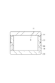
- FIG. 1 is an external view of an optical device according to an embodiment of the present invention.
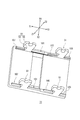
- FIG. 2 is an external perspective view for explaining the lens and the waterproof elastic member according to the embodiment of the present invention.
- FIG. 3 is an exploded perspective view of the optical device shown in FIG. 4 is an exploded perspective view of the optical device shown in FIG. 1 from an angle different from that in FIG.
- FIG. 5 is a perspective view for explaining the shapes of the first accommodation case and the second accommodation case of the optical device shown in FIG. 6 is a cross-sectional view taken along the line AA shown in FIG. 7 is a cross-sectional view taken along the line BB shown in FIG.
- FIG. 8 is an external perspective view of the first housing case shown in FIG. 1 as viewed from the side coupled to the second housing case.
- FIG. 9 is an external perspective view of the second housing case shown in FIG. 1 as viewed from the side coupled to the first housing case.
- FIG. 1 is an external view of an optical device 1 according to an embodiment of the present invention
- FIG. 2 is an external perspective view for explaining a lens 11 and a waterproof elastic member 35 of the present embodiment
- FIG. 3 is an optical device shown in FIG. 4 is an exploded perspective view of the optical device 1 shown in FIG. 1 from an angle different from that of FIG. 3
- FIG. 5 is a perspective view of the first storage case 31 and the second storage case 33 of the optical device 1. It is a perspective view for demonstrating the shape of this. 6 is a cross-sectional view taken along the line AA shown in FIG. 1, and FIG. 7 is a cross-sectional view taken along the line BB shown in FIG.
- the optical device 1 includes, for example, a lens 11, a lens housing case 13, and a waterproof elastic member 35.
- the lens housing case 13 includes a first housing case 31 and a second housing case 33.
- the optical device 1 is fixedly mounted on a predetermined device or the like.
- the first housing case 31 and the second housing case 33 together form a lens housing space 11 a that houses the lens 11.
- the first engaging portion 51 provided in the first housing case 31 can be elastically bent and deformed in the thickness direction (X1-X2 direction) of the second housing case 33 and is orthogonal (crossed) to the thickness direction. ) Having a support portion 53 extending in the extending direction (Z1-Z2 direction) and a hook 55 positioned on the tip side thereof.
- the second engaging portion 71 provided in the second housing case 33 is formed as a recess toward the lens housing space 11 a on the outer surface of the second housing case 33.
- the second engagement portion 71 is a state in which the support portion receiving portion 73 for receiving the support portion 53, the hook receiving portion 75 for receiving (accommodating) the hook 55, and the support portion 53 are not bent and deformed in the thickness direction.
- the hook 55 accommodated in the hook receiving portion 75 has a first restricting portion 77 that restricts movement of the hook 55 outside in the Z1-Z2 direction.
- the outer surface of the first engagement portion 51 is the periphery of the second engagement portion 71 of the second housing case 33. It becomes the same as the outer surface of.
- the lens 11 has a substantially rectangular parallelepiped shape, and has a shape that is point-symmetric with respect to the central axis.
- a concave portion 11b closed along the outer periphery is formed on the outer periphery near the one end side of the lens 11, and the waterproof elastic member 35 is fitted into the concave portion 11b.
- the first storage case 31 has a first engagement portion 51 that engages with the second engagement portion 71 of the second storage case 33.
- the first engaging portion 51 extends in the Z2 direction.
- the first engaging portion 51 is fixedly coupled to the second engaging portion 71 so as to be detachable.
- the first housing case 31 has a total of four first engaging portions 51 at positions symmetrical with respect to both the central axis in the Y1-Y2 direction and the central axis in the X1-X2 direction.
- the first engaging portion 51 includes a support portion 53 and a hook 55.
- the support portion 53 is elastically bent in the thickness direction (X1-X2 direction) of the second housing case 33. It is deformable and extends in the extending direction (Z1-Z2 direction) orthogonal to (intersecting with) the thickness direction.
- the hook 55 is located on the distal end side in the extending direction (Z2 direction) with respect to the support portion 53.
- a hook portion (notch) 55a for moving the first engagement portion 51 in the thickness direction by hooking it with a finger or the like is provided at the end of the hook 55 of the first engagement portion 51 on the Z2 direction side.
- the outer surfaces of the formed support part 53 and hook 55 are flush with the outer surface of the second case.
- the second housing case 33 has second engaging portions 71 at four positions facing the four first engaging portions 51 described above, and the second engaging portions. 71 is engaged (fixedly coupled) with the first engaging portion 51.
- the second engagement portion 71 has an accommodation space for accommodating the first engagement portion 51.
- the second engaging portion 71 includes a support portion accommodating portion 73, a hook receiving portion 75, and a first restricting portion 77.
- the support part accommodation part 73 accommodates the support part 53 when the first accommodation case 31 and the second accommodation case 33 are fixedly coupled.
- the hook receiving portion 75 receives (accommodates) the hook 55 when the first accommodation case 31 and the second accommodation case 33 are fixedly coupled.
- the first restricting portion 77 is located adjacent to the hook receiving portion 75 in the supporting portion accommodating portion 73 side (Z1 direction side) and adjacent to the supporting portion accommodating portion 73 in the Y1 direction.
- the hook 55 accommodated in the hook receiving portion 75 is moved in the extending direction (Z1 direction) while the support portion 53 is not bent and deformed in the thickness direction (X1-X2 direction), that is, The movement in the direction away from the hook receiving portion 75 is restricted (becomes locked).
- the 1st control part 77 does not perform the control mentioned above, when the support part 53 carries out the said bending deformation to the predetermined
- the first restricting portion 77 is provided on the inner side in the thickness direction (X1-X2 direction) of the second housing case 33 and has a thickness smaller than that of the second housing case 33.
- the 2nd control part 79 which is is provided.
- the second restricting portion 79 restricts the movement of the hook 55 accommodated in the hook receiving portion 75 to the lens accommodating space 11a.
- the tip of the hook 55 is Engaging with the end of the restricting portion 77, the support portion 53 is bent and deformed in the thickness direction (X1-X2 direction), and the hook 55 moves to a position avoiding the restricting portion 77, and the hook 55 is moved to the hook receiving portion 75.
- the support portion 53 is deformed by the restoring force and becomes a shape before being deformed, and the hook 55 moves toward the second restricting portion 79. That is, the lock state is entered.
- FIG. 8 is an external perspective view of the first housing case 31 shown in FIG. 1 as viewed from the side coupled to the second housing case 33.
- the first storage case 31 includes third restriction portions 101, 103, 105, and 107 at a plurality of positions facing the second storage case 33.
- the third restricting portion 101 is located between the two first engaging portions 51 located along the Y1-Y2 direction, and has a tapered surface that inclines in the Z2 direction toward the outside in the X1-X2 direction. is doing.
- a third restricting portion 105 is formed on the Y2 side with respect to the third restricting portion 101.
- a third restricting portion 103 is formed in the vicinity of the Y2 side end portion of the first housing case 31. Further, a third restricting portion 107 is formed in the vicinity of the end portion in the Y1 direction with respect to the first engaging portion 51.
- the third restricting portions 103, 105, and 107 have a tapered surface that is inclined in the Z2 direction toward the center in the X1-X2 direction.
- FIG. 9 is an external perspective view of the second housing case 33 shown in FIG. 1 as viewed from the side coupled to the first housing case 31.
- the second storage case 33 includes fourth restriction portions 201, 203, 205, and 207 at a plurality of positions facing the first storage case 31.
- the fourth restricting portion 201 is located between the two second engaging portions 71 located along the Y1-Y2 direction, and has a tapered surface that inclines in the Z1 direction toward the center in the X1-X2 direction. is doing.
- the tapered surface of the fourth restricting portion 201 is surface-joined with the tapered surface of the third restricting portion 101.
- a fourth restricting portion 205 is formed on the Y2 side with respect to the fourth restricting portion 201.
- a fourth restricting portion 203 is formed in the vicinity of the Y2 side end portion of the second housing case 33.
- a fourth restricting portion 207 is formed in the vicinity of the end portion in the Y1 direction with respect to the second engaging portion 71.
- the fourth restricting portions 203, 205, and 207 have tapered surfaces that incline in the Z1 direction toward the outside in the X1-X2 direction. When the first housing case 31 and the second housing case 33 are coupled, the tapered surfaces of the fourth restricting portions 203, 205, and 207 are tapered surfaces of the third restricting portions 103, 105, and 107. And surface-join.
- the first housing case 31 is restricted from moving relative to the second housing case 33 in the X1 direction by the surface bonding of the tapered surface with the 201. Further, the taper surfaces of the third restricting portions 103.105, 107 and the fourth restricting portions 203, 205, 207 on the X2 direction side and the third restricting portion 101 on the X1 direction side and the fourth restricting surface are connected. The first housing case 31 is restricted from moving relative to the second housing case 33 in the X2 direction by surface bonding of the tapered surface with the restricting portion 201.
- the waterproof elastic member 35 is fitted into the recess 11 b near one end of the lens 11.
- the first housing case 31 and the second housing case 33 are moved closer to the Z1-Z2 direction with a part of the lens 11 including the portion to which the waterproof elastic member 35 is attached interposed therebetween.
- the first engaging portion 51 and the second engaging portion 71 are fixedly coupled.
- the tip of the hook 55 of the first engaging portion 51 of the first housing case 31 is the end of the restricting portion 77 of the second engaging portion 71 of the second housing case 33 on the Z1 direction side.
- the support portion 53 is bent and deformed outward in the thickness direction (X1-X2 direction). Due to the bending deformation of the support portion 53, the hook 55 moves to a position where the restricting portion 77 is avoided, and the hook 55 is accommodated in the hook receiving portion 75 while avoiding the restricting portion 77 of the second engaging portion 71.
- the support portion 53 becomes a shape before being deformed by the restoring force, and the hook 55 moves toward the second restricting portion 79. Retained. That is, the lock state is entered.
- the first engaging portion 51 and the second engaging portion 71 are fixedly coupled at four positions between the first housing case 31 and the second housing case 33, and the lens 11 is stabilized. It is held in the state.
- the taper surface is joined to the restricting portion 201.
- the first housing case 31 is restricted from moving relative to the second housing case 33 in the X2 direction. This restricts the hook 33 from coming off from the lens housing case 21 in the Y1 direction.
- the second engaging portion 71 is formed as a recess toward the lens housing space 11a on the outer surface of the second housing case 33, and the first
- the outer surface of the first engaging portion 51 is
- the second housing case 33 is configured to be flush with the outer surface around the second engagement portion 71. Therefore, the first storage case 31 and the second storage case 33 can be coupled with a relatively small shape. That is, the lens housing case 13 can be reduced in size.
- the hook 55 can be moved in a direction to be detached from the hook receiving portion 75 in the Z1-Z2 direction only when an external force is applied. Thereby, the 1st engagement part 51 and the 2nd engagement part 71 can be attached or detached.
- the first restricting portion 77 is provided inside the second housing case 33 in the thickness direction, and is thinner than the second housing case 33. Therefore, the second housing case 33 can be downsized by the first restricting portion 77.
- the hook 55 can be prevented from coming into contact with the lens 11 and being damaged.
- the second restricting portion 79 is provided between the lens housing space 11a and a part of the hook receiving portion 75, the area of the second restricting portion 79 that is thin in the thickness direction can be reduced. Can be easily done.
- the first accommodating case 31 is restricted from moving relative to the second accommodating case 33 in the X1 direction. it can. Further, the taper surfaces of the third restricting portions 103.105, 107 and the fourth restricting portions 203, 205, 207 on the X2 direction side and the third restricting portion 101 on the X1 direction side and the fourth restricting surface are connected.
- the present invention is not limited to the embodiment described above. That is, those skilled in the art may make various modifications, combinations, subcombinations, and alternatives regarding the components of the above-described embodiments within the technical scope of the present invention or an equivalent scope thereof.
- four combinations of the first engagement portion 51 and the second engagement portion 71 are provided to couple the first accommodation case 31 and the second accommodation case 33 together. Although illustrated, you may couple
- the lens 11 is exemplified as the optical component of the present invention, but a light guide path other than the lens may be used.
- first restricting portions 77 are formed at two locations around the hook receiving portion 75.
- the first engaging portion 51 may be provided as a separate body instead of being formed integrally with the first housing case 31.
- first restricting portion 77 and the second restricting portion 79 may be provided separately from the second housing case 33 instead of being integrated with the second housing case 33.
- the present invention can be applied to an optical component housing case such as an optical component lens.
Landscapes
- Engineering & Computer Science (AREA)
- Mechanical Engineering (AREA)
- Studio Devices (AREA)
Abstract
Selon l'invention, une première partie d'accouplement 51 prévue au niveau d'un premier boîtier de stockage 31 comporte une partie de support 53, qui est susceptible de subir une déformation de flexion de manière élastique dans la direction de l'épaisseur et s'étend dans une direction d'étendue perpendiculaire à la direction d'épaisseur, et un crochet 55. Une seconde partie d'accouplement 71 d'un second boîtier de stockage 33 comporte une unité de réception de partie de support 73 destinée à recevoir la partie de support 53, une partie de réception de crochet 75 destinée à recevoir le crochet 55, et une première unité d'ajustement 77 servant à ajuster le mouvement du crochet 55, reçu par la partie de réception de crochet 75, dans une direction Z1 de telle sorte que la partie de support 53 ne soit ni fléchie ni déformée dans la direction de l'épaisseur.
Applications Claiming Priority (2)
| Application Number | Priority Date | Filing Date | Title |
|---|---|---|---|
| JP2016047438 | 2016-03-10 | ||
| JP2016-047438 | 2016-03-10 |
Publications (1)
| Publication Number | Publication Date |
|---|---|
| WO2017154483A1 true WO2017154483A1 (fr) | 2017-09-14 |
Family
ID=59790391
Family Applications (1)
| Application Number | Title | Priority Date | Filing Date |
|---|---|---|---|
| PCT/JP2017/005300 Ceased WO2017154483A1 (fr) | 2016-03-10 | 2017-02-14 | Boîtier de stockage de composant optique |
Country Status (1)
| Country | Link |
|---|---|
| WO (1) | WO2017154483A1 (fr) |
Citations (4)
| Publication number | Priority date | Publication date | Assignee | Title |
|---|---|---|---|---|
| JPS5634610Y2 (fr) * | 1977-07-11 | 1981-08-15 | ||
| JPS5827959Y2 (ja) * | 1976-12-15 | 1983-06-17 | 松下電工株式会社 | ケ−ス |
| JPS61107753U (fr) * | 1984-12-21 | 1986-07-08 | ||
| JP2013173549A (ja) * | 2012-02-24 | 2013-09-05 | Konica Minolta Inc | レンズ収納ケース |
-
2017
- 2017-02-14 WO PCT/JP2017/005300 patent/WO2017154483A1/fr not_active Ceased
Patent Citations (4)
| Publication number | Priority date | Publication date | Assignee | Title |
|---|---|---|---|---|
| JPS5827959Y2 (ja) * | 1976-12-15 | 1983-06-17 | 松下電工株式会社 | ケ−ス |
| JPS5634610Y2 (fr) * | 1977-07-11 | 1981-08-15 | ||
| JPS61107753U (fr) * | 1984-12-21 | 1986-07-08 | ||
| JP2013173549A (ja) * | 2012-02-24 | 2013-09-05 | Konica Minolta Inc | レンズ収納ケース |
Similar Documents
| Publication | Publication Date | Title |
|---|---|---|
| CN115061257B (zh) | 镜头驱动装置、照相机模块和移动电话 | |
| CN117572657A (zh) | 用于光学防抖的反射模块和包括该反射模块的相机模块 | |
| JP6691001B2 (ja) | 振れ補正機能付き光学ユニット | |
| JP2012251803A (ja) | モジュールおよび電子機器 | |
| KR20120122466A (ko) | 카메라 모듈 | |
| KR20160073763A (ko) | 렌즈 구동 장치 | |
| KR20240161620A (ko) | 렌즈 구동 장치 및 이를 포함하는 카메라 모듈 | |
| KR20200119031A (ko) | 회전 카메라를 포함하는 전자장치 | |
| JP2021032930A (ja) | 振れ補正機能付き光学ユニット | |
| CN111258148A (zh) | 光学单元 | |
| CN111284416B (zh) | 检测装置 | |
| US20210373615A1 (en) | Electronic device including connector to which accessory device is attachable | |
| KR102837211B1 (ko) | 카메라 모듈 및 이를 포함하는 전자 장치 | |
| JP2020160373A (ja) | 振れ補正機能付き光学ユニット | |
| CN111284414B (zh) | 检测装置 | |
| JP2013004617A (ja) | 筐体部品 | |
| WO2017154483A1 (fr) | Boîtier de stockage de composant optique | |
| KR20170104837A (ko) | 이동 단말기 | |
| US20140177143A1 (en) | Electronic apparatus | |
| JP2022545600A (ja) | エッチングされた光学組立体ハウジング | |
| US20120113350A1 (en) | Back frame and display device having the same | |
| JP7323412B2 (ja) | 振れ補正機能付き光学ユニット | |
| CN114217402A (zh) | 光学部件驱动装置、照相机装置以及电子设备 | |
| JP7076489B2 (ja) | 駆動装置、カメラ装置及び電子機器 | |
| WO2022000549A1 (fr) | Appareil d'entraînement d'objectif |
Legal Events
| Date | Code | Title | Description |
|---|---|---|---|
| NENP | Non-entry into the national phase |
Ref country code: DE |
|
| 121 | Ep: the epo has been informed by wipo that ep was designated in this application |
Ref document number: 17762826 Country of ref document: EP Kind code of ref document: A1 |
|
| 122 | Ep: pct application non-entry in european phase |
Ref document number: 17762826 Country of ref document: EP Kind code of ref document: A1 |
|
| NENP | Non-entry into the national phase |
Ref country code: JP |