WO2017154554A1 - ダンパ装置 - Google Patents
ダンパ装置 Download PDFInfo
- Publication number
- WO2017154554A1 WO2017154554A1 PCT/JP2017/006283 JP2017006283W WO2017154554A1 WO 2017154554 A1 WO2017154554 A1 WO 2017154554A1 JP 2017006283 W JP2017006283 W JP 2017006283W WO 2017154554 A1 WO2017154554 A1 WO 2017154554A1
- Authority
- WO
- WIPO (PCT)
- Prior art keywords
- sheet
- elastic member
- pressing plate
- disk
- flanged hub
- Prior art date
- Legal status (The legal status is an assumption and is not a legal conclusion. Google has not performed a legal analysis and makes no representation as to the accuracy of the status listed.)
- Ceased
Links
Images





Classifications
-
- F—MECHANICAL ENGINEERING; LIGHTING; HEATING; WEAPONS; BLASTING
- F16—ENGINEERING ELEMENTS AND UNITS; GENERAL MEASURES FOR PRODUCING AND MAINTAINING EFFECTIVE FUNCTIONING OF MACHINES OR INSTALLATIONS; THERMAL INSULATION IN GENERAL
- F16F—SPRINGS; SHOCK-ABSORBERS; MEANS FOR DAMPING VIBRATION
- F16F15/00—Suppression of vibrations in systems; Means or arrangements for avoiding or reducing out-of-balance forces, e.g. due to motion
- F16F15/10—Suppression of vibrations in rotating systems by making use of members moving with the system
- F16F15/12—Suppression of vibrations in rotating systems by making use of members moving with the system using elastic members or friction-damping members, e.g. between a rotating shaft and a gyratory mass mounted thereon
- F16F15/121—Suppression of vibrations in rotating systems by making use of members moving with the system using elastic members or friction-damping members, e.g. between a rotating shaft and a gyratory mass mounted thereon using springs as elastic members, e.g. metallic springs
- F16F15/123—Wound springs
- F16F15/1232—Wound springs characterised by the spring mounting
- F16F15/12326—End-caps for springs
- F16F15/12333—End-caps for springs having internal abutment means
-
- F—MECHANICAL ENGINEERING; LIGHTING; HEATING; WEAPONS; BLASTING
- F16—ENGINEERING ELEMENTS AND UNITS; GENERAL MEASURES FOR PRODUCING AND MAINTAINING EFFECTIVE FUNCTIONING OF MACHINES OR INSTALLATIONS; THERMAL INSULATION IN GENERAL
- F16D—COUPLINGS FOR TRANSMITTING ROTATION; CLUTCHES; BRAKES
- F16D13/00—Friction clutches
- F16D13/58—Details
- F16D13/60—Clutching elements
- F16D13/64—Clutch-plates; Clutch-lamellae
-
- F—MECHANICAL ENGINEERING; LIGHTING; HEATING; WEAPONS; BLASTING
- F16—ENGINEERING ELEMENTS AND UNITS; GENERAL MEASURES FOR PRODUCING AND MAINTAINING EFFECTIVE FUNCTIONING OF MACHINES OR INSTALLATIONS; THERMAL INSULATION IN GENERAL
- F16F—SPRINGS; SHOCK-ABSORBERS; MEANS FOR DAMPING VIBRATION
- F16F1/00—Springs
- F16F1/02—Springs made of steel or other material having low internal friction; Wound, torsion, leaf, cup, ring or the like springs, the material of the spring not being relevant
- F16F1/04—Wound springs
- F16F1/12—Attachments or mountings
-
- F—MECHANICAL ENGINEERING; LIGHTING; HEATING; WEAPONS; BLASTING
- F16—ENGINEERING ELEMENTS AND UNITS; GENERAL MEASURES FOR PRODUCING AND MAINTAINING EFFECTIVE FUNCTIONING OF MACHINES OR INSTALLATIONS; THERMAL INSULATION IN GENERAL
- F16F—SPRINGS; SHOCK-ABSORBERS; MEANS FOR DAMPING VIBRATION
- F16F15/00—Suppression of vibrations in systems; Means or arrangements for avoiding or reducing out-of-balance forces, e.g. due to motion
- F16F15/10—Suppression of vibrations in rotating systems by making use of members moving with the system
- F16F15/12—Suppression of vibrations in rotating systems by making use of members moving with the system using elastic members or friction-damping members, e.g. between a rotating shaft and a gyratory mass mounted thereon
- F16F15/121—Suppression of vibrations in rotating systems by making use of members moving with the system using elastic members or friction-damping members, e.g. between a rotating shaft and a gyratory mass mounted thereon using springs as elastic members, e.g. metallic springs
- F16F15/123—Wound springs
Definitions
- the present invention relates to a damper device used for a clutch disk or the like.
- Japanese Patent No. 3381396 discloses a conventional damper device used for a clutch disk or the like.
- a flanged hub and a plate disposed around the hub of the flanged hub so as to face the flange of the flanged hub are elastically connected via a spring in the circumferential direction.
- the input from the plate side is transmitted to the flanged hub side via the spring while being buffered by the bending contraction of the spring.
- Such a conventional damper device has a problem that, as the rotational speed increases, an unintended hysteresis torque, which is different from the design time, is generated in the rotational vibration absorption near the beginning of the spring deflection.
- the present invention has been created based on the above knowledge.
- the objective of this invention is providing the damper apparatus which can suppress generation
- the damper device comprises: A pressing plate; A rotating plate arranged to face the pressing plate; An elastic member that elastically connects the pressing plate and the rotating plate in the circumferential direction; A sheet provided on an end face in a circumferential direction of the elastic member; With The sheet has a convex surface protruding in the circumferential direction on the inner diameter side, Each of the pressing plate and the rotating plate has a concave surface that can be fitted to the convex surface, In a state where the convex surface of the sheet is fitted to the concave surface of the rotating plate, a gap is formed between the convex surface of the sheet and the concave surface of the pressing plate.
- a gap is formed between the convex surface of the sheet and the concave surface of the pressing plate. Even in the case where the separation is repeated, surface sliding does not occur between the convex surface of the sheet and the concave surface of the pressing plate. Thereby, generation
- the sheet has a contact portion that can come into contact with the pressing plate on an outer diameter side, and when the pressing plate presses the sheet and starts bending the elastic member, A gap may be formed between the convex surface of the sheet and the concave surface of the pressing plate.
- the sheet when the pressing plate further presses the sheet, the sheet may rotate about the contact portion so that the convex surface of the sheet is fitted to the concave surface of the pressing plate.
- the sheet presses the outer diameter side of the elastic member, and the sheet rotates to rotate the sheet. After the convex surface is fitted into the concave surface of the pressing plate, the sheet may press the central axis of the elastic member.
- FIG. 1 is a schematic plan view of a damper device according to an embodiment of the present invention.
- FIG. 2 is a cross-sectional view taken along line AA of a part of the damper device shown in FIG.
- FIG. 3 is a sectional view taken along line BB of the damper device shown in FIG. 4 is a cross-sectional view taken along the line CC of the damper device shown in FIG. 2, and is a cross-sectional view of the damper device in an initial state.
- FIG. 5 is a cross-sectional view taken along line CC of the damper device shown in FIG. 2, and is a cross-sectional view of the damper device when the flanged hub contacts the seat during rotation.
- FIG. 6 is a cross-sectional view taken along the line CC of the damper device shown in FIG. 2, and is a cross-sectional view of the damper device when the flanged hub is separated from the seat during rotation.
- FIG. 7 is a cross-sectional view taken along line CC of the damper device shown in FIG. 2, and is a cross-sectional view of the damper device when the flanged hub presses the seat during rotation.
- FIG. 8 is a cross-sectional view of a conventional damper device when the flanged hub contacts the seat during rotation.
- FIG. 9 is a cross-sectional view of a conventional damper device when the flanged hub is separated from the seat during rotation. It is a figure which shows the twist property of a damper apparatus. It is a figure for demonstrating the hysteresis torque of the conventional damper apparatus. It is a figure for demonstrating the hysteresis torque of the damper apparatus by one embodiment of this invention.
- FIG. 1 is a schematic plan view of a damper device according to an embodiment of the present invention.
- FIG. 2 is a cross-sectional view taken along line AA of a part of the damper device shown in FIG.
- FIG. 3 is a cross-sectional view taken along the line BB of the seat 21 of the damper device shown in FIG. 4 is a cross-sectional view taken along the line CC of the damper device shown in FIG. 2, and is a cross-sectional view of the damper device in an initial state.
- FIG. 5 is a cross-sectional view taken along line CC of the damper device shown in FIG. 2, and is a cross-sectional view of the damper device when the flanged hub contacts the seat during rotation.
- FIG. 6 is a cross-sectional view taken along the line CC of the damper device shown in FIG. 2, and is a cross-sectional view of the damper device when the flanged hub is separated from the seat during rotation.
- FIG. 7 is a cross-sectional view taken along line CC of the damper device shown in FIG. 2, and is a cross-sectional view of the damper device when the flanged hub presses the seat during rotation.
- the damper device 10 includes a flanged hub 11, a disk plate 12 disposed so as to face the flanged hub 11, and the flanged hub 11 and the disk plate 12.
- the elastic member 14 is elastically connected in the disk circumferential direction, and the sheets 21 and 22 are provided on the end surface of the elastic member 14 in the disk circumferential direction.
- the flanged hub 11 corresponds to the “pressing plate” in the claims
- the disk plate 12 corresponds to the “rotating plate” in the claims.
- the damper device 10 is used for, for example, a clutch disk of a friction clutch disposed between an automobile engine and a transmission.
- a large number of corrugated leaf springs in which facings 51 that can be sandwiched between a flywheel as a drive shaft and a pressure plate are fixed on both sides by rivets 52, are fixed to the outer peripheral portion of the disk plate 12 by rivets.
- a transmission input shaft as an output shaft is spline-fitted to the hub of the flanged hub 11.
- the flanged hub 11 has a cylindrical hub and a flange 11F (see FIG. 2) extending in the disk radial direction from the outer periphery of the hub.
- the disk plate 12 has a substantially disc shape, and is disposed around the hub of the flanged hub 11 so as to face the flange 11F.
- the elastic member 14 is a coil spring in the illustrated example, but may be rubber or the like as long as it is an elastic body. In the following description, the elastic member 14 may be called a spring.
- the disk plate 12 has a plurality of windows 12W extending in the disk circumferential direction, and the flange 11F of the flanged hub 11 has a plurality of notches 11W facing the window 12W. Is formed.
- the opposing window 12W and the notch 11W constitute one set, and the elastic member 14 is arranged in a state in which the elastic member 14 is bent and contracted by a predetermined amount in the set window 12W and notch 11W. As a result, the elastic member 14 is assembled to the flanged hub 11 and the disk plate 12.
- the sheets 21 and 22 have the reaction force of the elastic member 14 between the disk circumferential end surface of the elastic member 14 and the disk 12W and notch 11W disk circumferential end surfaces. It is arrange
- a spring that holds the spring 14 by being fitted inside the coil of the spring 14 at the central portion in the radial direction of the disk on one side of the sheets 21 and 22 that contacts the end surface of the elastic member 14 in the circumferential direction of the disk.
- Holding protrusions 21b and 22b are provided so as to protrude in the disk circumferential direction with respect to the one side surface.
- sheet outer periphery holding portions 21c and 22c for holding the outer periphery of the spring 14 are provided so as to protrude in the disk circumferential direction with respect to the one side surface.
- convex surfaces 21a and 22a having a semicircular cross section extending in the disk axial direction protrude in the disk circumferential direction with respect to the other side surface. So as to be integrated.
- the portion 21 a 1 of the convex surface 21 a of the sheet 21 that faces the disk circumferential end surface of the window 12 ⁇ / b> W of the disk plate 12 is the circumferential direction of the notch 11 ⁇ / b> W of the flanged hub 11. It is formed so as to protrude in the disk circumferential direction as compared with the portion 21a2 facing the end face.
- the convex surface 22a of the other sheet 22 is also formed in the same shape.
- the notches 11W of the flanged hub 11 and the disk circumferential end surfaces of the windows 12W of the disk plate 12 are convex surfaces facing the convex surfaces 21a and 22a of the sheets 21 and 22, respectively.
- Semicircular concave surfaces 11a and 12a having the same cross-sectional shape as 21a and 22a are formed.
- the convex surfaces 21a and 22a of the sheets 21 and 22 are inserted into the concave surface 11a of the flanged hub 11 or the concave surface 12a of the disk plate 12, whereby the sheets 21 and 22 are inserted into the flanged hub 11 or the disk plate 12 in the disk periphery. It can be held in direction and radial direction.
- the window 12 ⁇ / b> W of the disk plate 12 has a fan-side shape, and in an initial state where there is no rotation, the convex surfaces 21 a and 22 a of the sheets 21 and 22 are formed on the concave surface 12 a of the disk plate 12.
- the outer circumferential portion of the disk 12W in the circumferential direction of the disk is inclined by a predetermined angle ⁇ with respect to the opposing side surfaces of the sheets 21 and 22.
- a centrifugal force outward in the disk radial direction is applied to the sheets 21 and 22 during rotation, the sheets 21 and 22 center on the contact portion 26 with the disk plate 12.
- the plate 12 is rotated by a predetermined angle ⁇ , whereby the convex surfaces 21 a and 22 a of the sheets 21 and 22 are fitted and held on the concave surface 12 a of the disk plate 12.
- the notch 11W of the flanged hub 11 has a fan-side shape, and the convex surfaces 21a and 22a of the sheets 21 and 22 are fitted into the concave surface 12a of the disk plate 12.
- a gap 31 is formed between the convex surfaces 21 a and 21 b of the sheets 21 and 22 and the concave surface 11 a of the flanged hub 11.
- the sheet 21 has a contact portion 25 that can come into contact with the flanged hub 11 on the outer side in the disk radial direction, and the flanged hub 11 presses the sheet 21 to press the elastic member 14.
- a gap 31 is formed between the convex surface 21a of the sheet 21 and the concave surface 11a of the flanged hub 11.
- the damper device 10 is provided with a known hysteresis mechanism, and gives a hysteresis to the torsional characteristics when the flanged hub 11 and the disk plate 12 rotate relative to each other.
- the damping action is exerted on the torque transmission from the disk plate 12 to the flanged hub 11.
- a configuration described in paragraph 0013 of Japanese Patent No. 338396 can be employed.
- the convex surfaces 21 a and 22 a of the sheets 21 and 22 are fitted to the concave surface 12 a of the disk plate 12 by rotating the sheets 21 and 22 by a predetermined angle ⁇ with respect to the disk plate 12. Thereby, the sheets 21 and 22 can be reliably held.
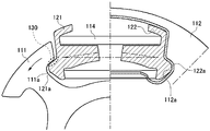
- the sheet 121, 122 a has the convex surface 121 a, 122 a fitted in the concave surface 112 a of the disk plate 112.
- the convex surface 121a and the concave surface 111a of the flanged hub 111 have contact portions 130 that come into contact with each other.
- the flanged hub 111 repeatedly presses and separates from the sheet 121. Further, surface sliding occurs at the contact portion 130 between the concave surface 111a of the flange 111F and the convex surface 121a of the sheet 121. As the rotational speed of the damper device increases, the centrifugal force applied to the sheets 121 and 122 increases, so that the surface sliding also increases. Due to the influence of this surface sliding, an unintended hysteresis torque different from that at the time of design is generated as shown in FIG.
- the sheet 21 rotates about the contact portion 25 by a predetermined angle ⁇ , so that the convex surface 21 a of the sheet 21 is the concave surface 11 a of the flanged hub 11. To fit. Thereby, the sheet 21 can be reliably pressed and held.
- the sheet 21 presses the outer diameter side of the elastic member 14.
- the sheet 21 presses the central axis of the elastic member 14 (in other words, the elastic member 14 Press the outer diameter side and inner diameter side evenly).
- the torque step in the damper device 10 can be reduced by pressing the elastic member 14 stepwise.
- the flanged hub 11 presses the sheet 21 and starts to bend the elastic member 14, there is a gap between the convex surface 21 a of the sheet 21 and the concave surface 11 a of the flanged hub 11. Since the flanged hub 11 and the seat 21 are in contact with each other at one point of the contact portion 25, unintended hysteresis torque due to surface sliding can be reliably prevented.
- the sheet 21 rotates around the contact portion 25 so that the convex surface 21a of the sheet 21 fits into the concave surface 11a of the flanged hub 11. Therefore, the sheet 21 can be reliably pressed and held.
- the flanged hub 11 presses the sheet 21 and starts to bend the elastic member 14, the sheet 21 presses the outer diameter side of the elastic member 14, and the sheet 21 rotates. Then, after the convex surface 21a of the sheet 21 is fitted to the concave surface 11a of the flanged hub 11, the sheet 21 presses the central axis of the elastic member 14, so the elastic member 14 is pressed stepwise. Thus, the torque step of the damper device 10 is reduced.
- the portion 21 a 1 of the convex surface 21 a of the sheet 21 that faces the disk circumferential end surface of the window 12 ⁇ / b> W of the disk plate 12 is formed on the notch 11 ⁇ / b> W of the flanged hub 11. It is formed so as to protrude in the disk circumferential direction as compared with the portion 21a2 facing the disk circumferential end surface, but the present invention is not limited to this.
- the concave surface 11 a of the flanged hub 11 may be formed so as to be immersed in the circumferential direction of the disk as compared with the concave surface 12 a of the disk plate 12.
- the gap 31 can be formed between the convex surface 21a of the sheet 21 and the concave surface 11a of the flanged hub 11 in a state where the convex surface 21a of the sheet 21 is fitted to the concave surface 12a of the disk plate 12.
- the flanged hub 11 corresponds to the “pressing plate” in the claims
- the disk plate 12 corresponds to the “rotating plate” in the claims. It is not limited to this.
- the disk plate 12 may correspond to the “pressing plate” in the claims
- the flanged hub 11 may correspond to the “rotating plate” in the claims.
- the torque input to the flanged hub 11 is transmitted to the disk plate 12 via the elastic member 14 while being buffered by the flexion and contraction of the elastic member 14. The same effect can be obtained.
Landscapes
- Engineering & Computer Science (AREA)
- General Engineering & Computer Science (AREA)
- Mechanical Engineering (AREA)
- Physics & Mathematics (AREA)
- Acoustics & Sound (AREA)
- Aviation & Aerospace Engineering (AREA)
- Mechanical Operated Clutches (AREA)
- Springs (AREA)
Abstract
ダンパ装置は、押圧プレートと、押圧プレートに対向するように配置された回転プレートと、押圧プレートと回転プレートとを周方向において弾性的に連結する弾性部材と、弾性部材の周方向の端面に設けられたシートと、を備える。シートは、内径側において周方向に突出する凸面を有する。押圧プレート及び回転プレートは、それぞれ、シートの凸面と嵌合可能な凹面を有する。シートの凸面が回転プレートの凹面に嵌合した状態では、シートの凸面と押圧プレートの凹面との間に隙間31が形成されている。
Description
本発明は、クラッチディスク等に利用されるダンパ装置に関する。
特許第3381396号公報には、クラッチディスク等に利用される従来のダンパ装置が開示されている。このダンパ装置は、フランジ付きハブとフランジ付きハブのフランジに対して対向するようにフランジ付きハブのハブ周りに配置されたプレートとをスプリングを介して周方向において弾性的に連結したものであり、プレート側からの入力をスプリングの撓み収縮により緩衝させながらスプリングを介してフランジ付きハブ側に伝達している。
このような従来のダンパ装置では、回転数が高くなるほど、スプリングの撓み始め付近の回転振動吸収において、設計時とは異なる意図しないヒステリシストルクが発生するという問題がある。
本件発明者らは、このような問題点に着目して鋭意研究を重ねた結果、スプリングの撓み始め付近の回転振動吸収では、フランジ付きハブのフランジがスプリングの端面のシートに対して押圧と離間を繰り返す際に、フランジとシートとの間で面摺動が発生し、この面摺動が意図しないヒステリシストルクを引き起こしていることを知見した。
本発明は、以上のような知見に基づいて創案されたものである。本発明の目的は、意図しないヒステリシストルクの発生を抑制できるダンパ装置を提供することにある。
本発明によるダンパ装置は、
押圧プレートと、
前記押圧プレートに対向するように配置された回転プレートと、
前記押圧プレートと前記回転プレートとを周方向において弾性的に連結する弾性部材と、
前記弾性部材の周方向の端面に設けられたシートと、
を備え、
前記シートは、内径側において周方向に突出する凸面を有し、
前記押圧プレート及び前記回転プレートは、それぞれ、前記凸面と嵌合可能な凹面を有し、
前記シートの凸面が前記回転プレートの凹面に嵌合した状態では、前記シートの凸面と前記押圧プレートの凹面との間に隙間が形成されている。
押圧プレートと、
前記押圧プレートに対向するように配置された回転プレートと、
前記押圧プレートと前記回転プレートとを周方向において弾性的に連結する弾性部材と、
前記弾性部材の周方向の端面に設けられたシートと、
を備え、
前記シートは、内径側において周方向に突出する凸面を有し、
前記押圧プレート及び前記回転プレートは、それぞれ、前記凸面と嵌合可能な凹面を有し、
前記シートの凸面が前記回転プレートの凹面に嵌合した状態では、前記シートの凸面と前記押圧プレートの凹面との間に隙間が形成されている。
本発明によれば、シートの凸面が回転プレートの凹面に嵌合した状態では、シートの凸面と押圧プレートの凹面との間に隙間が形成されているため、押圧プレートがシートに対して押圧と離間を繰り返すような場合においても、シートの凸面と押圧プレートの凹面との間にて面摺動が発生しない。これにより、弾性部材の撓みを開始する時点において、意図しないヒステリシストルクの発生が抑制され得る。
本発明によるダンパ装置において、前記シートは、外径側において前記押圧プレートと接触可能な接触部を有し、前記押圧プレートが前記シートを押圧して前記弾性部材の撓みを開始する時点において、前記シートの凸面と前記押圧プレートの凹面との間に隙間が形成されていてもよい。
本発明によるダンパ装置において、前記押圧プレートが前記シートを更に押圧する時、前記シートは前記接触部を中心に回転して前記シートの凸面が前記押圧プレートの凹面に嵌合してもよい。
本発明によるダンパ装置において、前記押圧プレートが前記シートを押圧して前記弾性部材の撓みを開始する時点において、前記シートは前記弾性部材の外径側を押圧し、前記シートが回転して前記シートの凸面が前記押圧プレートの凹面に嵌合した後に、前記シートは前記弾性部材の中心軸を押圧してもよい。
以下に、添付の図面を参照して、本発明の実施の形態を詳細に説明する。なお、以下に説明する実施の形態は、本発明を実施する場合の一例を示すものであって、本発明を以下に説明する具体的構成に限定するものではない。本発明の実施にあたっては、実施の形態に応じた具体的構成が適宜採用されてよい。
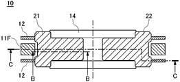
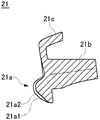
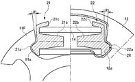
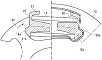
図1は、本発明の一実施の形態によるダンパ装置の概略平面図である。図2は、図1に示すダンパ装置の一部のA-A線に沿った断面図である。図3は、図2に示すダンパ装置のシート21のB-B線に沿った断面図である。図4は、図2に示すダンパ装置のC-C線に沿った断面図であって、初期状態におけるダンパ装置の断面図である。図5は、図2に示すダンパ装置のC-C線に沿った断面図であって、回転時においてフランジ付きハブがシートに接触する時のダンパ装置の断面図である。図6は、図2に示すダンパ装置のC-C線に沿った断面図であって、回転時においてフランジ付きハブがシートから離間する時のダンパ装置の断面図である。図7は、図2に示すダンパ装置のC-C線に沿った断面図であって、回転時においてフランジ付きハブがシートを押圧する時のダンパ装置の断面図である。
図1に示すように、本実施の形態によるダンパ装置10は、フランジ付きハブ11と、フランジ付きハブ11に対向するように配置されたディスクプレート12と、フランジ付きハブ11とディスクプレート12とをディスク周方向において弾性的に連結する弾性部材14と、弾性部材14のディスク周方向の端面に設けられたシート21、22と、を備えている。本実施の形態では、フランジ付きハブ11が特許請求の範囲の「押圧プレート」に対応し、ディスクプレート12が特許請求の範囲の「回転プレート」に対応している。
本実施の形態によるダンパ装置10は、例えば自動車のエンジンと変速機との間に配設される摩擦クラッチのクラッチディスクの用途に用いられる。この場合、駆動軸としてのフライホイールとプレッシャープレートとの間に挟着され得るフェーシング51がリベット52により両側に固定された多数の波付板バネが、ディスクプレート12の外周部にリベットにより固定される。また、出力軸としての変速機インプットシャフトが、フランジ付きハブ11のハブにスプライン嵌合される。
フランジ付きハブ11は、円筒形状のハブと、ハブの外周からディスク径方向に延在するフランジ11F(図2参照)と、を有している。ディスクプレート12は、略円板形状を有しており、フランジ付きハブ11のハブ周りにフランジ11Fに対向するように配置されている。
弾性部材14は、図示された例ではコイルスプリングであるが、弾性体であればゴム等であってもよい。以下の説明では、弾性部材14をスプリングと呼ぶことがある。
図1に示すように、ディスクプレート12には、ディスク周方向に延在する複数の窓12Wが形成されており、フランジ付きハブ11のフランジ11Fには、窓12Wと対向する複数の切欠き11Wが形成されている。この対向する窓12W及び切欠き11Wにて一つの組が構成され、この組となる窓12W及び切欠き11W内に組毎に弾性部材14が所定量撓み収縮された状態で配置されている。これにより、弾性部材14は、フランジ付きハブ11及びディスクプレート12に対して組み付けられる。
図2及び図4~図7に示すように、シート21、22は、弾性部材14のディスク周方向端面と窓12W及び切欠き11Wのディスク周方向端面との間に、弾性部材14の反力にて挟持された状態で配設されている。したがって、窓12Wのディスク周方向端面及び切欠き11Wのディスク周方向端面は、シート21、22を介して弾性部材14のディスク周方向端面と当接し得る。
図示された例では、シート21、22のうち弾性部材14のディスク周方向端面と当接する一方の側面のディスク径方向中央部に、スプリング14のコイル内側に嵌挿されてスプリング14を保持するスプリング保持突起部21b、22bが、当該一方の側面に対してディスク周方向に突出するように設けられている。また、当該一方の側面のディスク径方向外側には、スプリング14の外周を保持するシート外周保持部21c、22cが、当該一方の側面に対してディスク周方向に突出するように設けられている。
一方、シート21、22のうち他方の側面のディスク径方向内側には、ディスク軸方向に延在する断面半円形状の凸面21a、22aが、当該他方の側面に対してディスク周方向に突出するように一体に設けられている。
本実施の形態では、図3に示すように、シート21の凸面21aのうちディスクプレート12の窓12Wのディスク周方向端面と対向する部分21a1は、フランジ付きハブ11の切欠き11Wのディスク周方向端面と対向する部分21a2に比べて、ディスク周方向に突出するように形成されている。図示は省略するが、他方のシート22の凸面22aも同様の形状にて形成されている。
図4~図7に示すように、フランジ付きハブ11の切欠き11W及びディスクプレート12の窓12Wのディスク周方向端面には、それぞれ、シート21、22の凸面21a、22aと対向するように凸面21a、22aと同一の断面形状である半円形状の凹面11a、12aが形成されている。シート21、22の凸面21a、22aはフランジ付きハブ11の凹面11aまたはディスクプレート12の凹面12a内に嵌挿され、これにより、シート21、22は、フランジ付きハブ11またはディスクプレート12にディスク周方向及び径方向において保持され得る。
図4に示すように、ディスクプレート12の窓12Wは、扇側形状を呈するものであって、回転がない初期状態においては、シート21、22の凸面21a、22aがディスクプレート12の凹面12aに当接されており、窓12Wのディスク周方向端面のうちディスク径方向外側部分は、シート21、22の対向する側面に対して所定角度αだけ傾斜している。これにより、図5に示すように、回転時にシート21、22に対してディスク径方向外向きの遠心力が加わると、シート21、22は、ディスクプレート12との接触部26を中心に、ディスクプレート12に対して所定角度αだけ回転し、これにより、シート21、22の凸面21a、22aがディスクプレート12の凹面12aに嵌合して保持される。
また、図5及び図6に示すように、フランジ付きハブ11の切欠き11Wは、扇側形状を呈するものであって、シート21、22の凸面21a、22aがディスクプレート12の凹面12aに嵌合して保持された状態では、シート21、22の凸面21a、21bとフランジ付きハブ11の凹面11aとの間に隙間31が形成されている。
さらに、図5に示すように、シート21は、ディスク径方向外側においてフランジ付きハブ11と接触可能な接触部25を有しており、フランジ付きハブ11がシート21を押圧して弾性部材14の撓みを開始する時点において、シート21の凸面21aとフランジ付きハブ11の凹面11aとの間に隙間31が形成されている。
より詳しくは、図5に示すように、フランジ付きハブ11がシート21を押圧して弾性部材14の撓みを開始する時点において、フランジ付きハブ11の切欠き11Wのディスク周方向端面は、シート21の対向する側面に対して所定角度βだけ傾斜している。これにより、図7に示すように、フランジ付きハブ11がシート21を更に押圧する時に、シート21は、フランジ付きハブ11に対する接触部25を中心に、フランジ付きハブ11に対して所定角度βだけ回転し、これにより、シート21の凸面21aはフランジ付きハブ11の凹面11aに嵌合して保持され得る。
図5に示すように、フランジ付きハブ11がシート21を押圧して弾性部材14の撓みを開始する時点では、フランジ付きハブ11からの押圧力がシート21のディスク径方向外側の接触部25に加わるため、シート21は弾性部材14の外径側を押圧する。一方、図7に示すように、シート21の凸面21aがフランジ付きハブ11の凹面11aに嵌合して保持された状態では、フランジ付きハブ11からの押圧力がシート21の対向する側面に均等に加わるため、シート21は弾性部材14を外径側と内径側とを均等に押圧する。
次に、このような構成からなるダンパ装置10の動作について説明する。
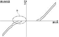
クラッチの接続時、エンジンからのトルクは、フェーシング51及び波付板バネを介してディスクプレート12に入力され、ディスクプレート12から弾性部材14を介してフランジ付きハブ11に伝達され、フランジ付きハブ11から変速機へと出力される。この時、フランジ付きハブ11とディスクプレート12とが入力されたトルク値に応じて弾性部材14を撓み収縮させながら、図10に示される捩じれ特性にて相対捩じれ回転し、これにより、ディスクプレート12からフランジ付きハブ11へのトルク伝達に緩衝作用が働く。
クラッチの接続時、エンジンからのトルクは、フェーシング51及び波付板バネを介してディスクプレート12に入力され、ディスクプレート12から弾性部材14を介してフランジ付きハブ11に伝達され、フランジ付きハブ11から変速機へと出力される。この時、フランジ付きハブ11とディスクプレート12とが入力されたトルク値に応じて弾性部材14を撓み収縮させながら、図10に示される捩じれ特性にて相対捩じれ回転し、これにより、ディスクプレート12からフランジ付きハブ11へのトルク伝達に緩衝作用が働く。
なお、図示は省略するが、ダンパ装置10には、それ自体は公知のヒステリシス機構が設けられており、フランジ付きハブ11とディスクプレート12とが相対捩じれ回転する際の捩じれ特性にヒステリシスを持たせ、ディスクプレート12からフランジ付きハブ11へのトルク伝達に減衰作用を働かせている。ヒステリシス機構としては、例えば特許第3381396号公報の段落0013に記載されたような構成を採用することができる。
本実施の形態では、図4及び図5に示すように、ダンパ装置10に回転が加わると、シート21、22は、ディスク径方向外向きの遠心力を受けることで、ディスクプレート12との接触部26を中心に所定角度αだけ回転する。これにより、弾性部材14の撓み収縮による捩じれ特性の前に、シート21、22の回転により捩じれ特性が得られる。
図5に示すように、シート21、22がディスクプレート12に対して所定角度αだけ回転することで、シート21、22の凸面21a、22aはディスクプレート12の凹面12aに嵌合する。これにより、シート21、22の確実な保持が可能となる。
ところで、上記でも言及したように、従来のダンパ装置では、図8及び図9に示すように、シート121、122の凸面121a、122aがディスクプレート112の凹面112aに嵌合した状態において、シート121の凸面121aとフランジ付きハブ111の凹面111aとは互いに接触する接触部分130を有している。
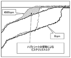
そのため、スプリング114の撓み始め付近の回転振動吸収(図10における符号Dを付した一点鎖線で囲われた領域に対応する)では、フランジ付きハブ111がシート121に対して押圧と離間を繰り返す際に、フランジ111Fの凹面111aとシート121の凸面121aとの間の接触部分130にて面摺動が発生する。ダンパ装置の回転数が高くなるほど、シート121、122に加わる遠心力が大きくなるため、面摺動も大きくなる。この面摺動の影響により、図11に示すように、設計時とは異なる意図しないヒステリシストルクが発生することになる。
一方、本実施の形態では、図5及び図6に示すように、シート21、22の凸面21a、22aがディスクプレート12の凹面12aに嵌合した状態では、シート21の凸面21aとフランジ付きハブ11の凹面11aとの間に隙間31が形成されている。そのため、フランジ付きハブ11がシート21に対して押圧と離間を繰り返すような場合においても、シート21の凸面21aとフランジ付きハブ11の凹面11aとの間で面摺動が発生しない。これにより、図12に示すように、スプリング14の撓み始め付近の回転振動吸収(図12における符号Dを付した一点鎖線で囲われた領域に対応する)において、設計時と同様のヒステリシストルクが実現され得る。
また、本実施の形態では、図5に示すように、フランジ付きハブ11がシート21を押圧して弾性部材14の撓みを開始する時点において、フランジ付きハブ11とシート21とが接触部25の一点にて接触するので、面摺動に起因する意図しないヒステリシストルクの発生が確実に防止され得る。
図7に示すように、フランジ付きハブ11がシート21を更に押圧する時、シート21は接触部25を中心に所定角度βだけ回転して、シート21の凸面21aがフランジ付きハブ11の凹面11aに嵌合する。これにより、シート21の確実な押圧及び保持が可能となる。
ここで、図5に示すように、フランジ付きハブ11がシート21を押圧して弾性部材14の撓みを開始する時点では、シート21は弾性部材14の外径側を押圧するが、図7に示すように、シート21が回転してシート21の凸面21aがフランジ付きハブ11の凹面11aに嵌合した後では、シート21は弾性部材14の中心軸を押圧する(言い換えれば、弾性部材14の外径側及び内径側を均等に押圧する)。このように、弾性部材14が段階的に押圧されることにより、ダンパ装置10におけるトルク段差が低減され得る。
以上のように、本実施の形態によれば、シート21の凸面21aがディスクプレート12の凹面12aに嵌合した状態では、シート21の凸面21aとフランジ付きハブ11の凹面11aとの間に隙間が形成されているため、フランジ付きハブ11がシート21に対して押圧と離間を繰り返すような場合においても、シート21の凸面21aとフランジ付きハブ11の凹面11aとの間にて面摺動が発生しない。これにより、弾性部材14の撓みを開始する時点において、意図しないヒステリシストルクの発生が抑制され得る。
また、本実施の形態によれば、フランジ付きハブ11がシート21を押圧して弾性部材14の撓みを開始する時点において、シート21の凸面21aとフランジ付きハブ11の凹面11aとの間に隙間が形成されており、フランジ付きハブ11とシート21とが接触部25の一点にて接触するため、面摺動に起因する意図しないヒステリシストルクの発生が確実に防止され得る。
また、本実施の形態によれば、フランジ付きハブ11がシート21を更に押圧する時に、シート21は接触部25を中心に回転してシート21の凸面21aがフランジ付きハブ11の凹面11aに嵌合するため、シート21の確実な押圧及び保持が可能となる。
また、本実施の形態によれば、フランジ付きハブ11がシート21を押圧して弾性部材14の撓みを開始する時点において、シート21は弾性部材14の外径側を押圧し、シート21が回転してシート21の凸面21aがフランジ付きハブ11の凹面11aに嵌合した後に、シート21は弾性部材14の中心軸を押圧するため、弾性部材14が段階的に押圧されることになり、これにより、ダンパ装置10のトルク段差が低減される。
なお、上述した実施の形態では、図3に示すように、シート21の凸面21aのうちディスクプレート12の窓12Wのディスク周方向端面と対向する部分21a1が、フランジ付きハブ11の切欠き11Wのディスク周方向端面と対向する部分21a2に比べて、ディスク周方向に突出するように形成されていたが、本発明はこれに限定されない。例えば、フランジ付きハブ11の凹面11aが、ディスクプレート12の凹面12aに比べて、ディスク周方向に没入するように形成されていてもよい。このような態様によっても、シート21の凸面21aがディスクプレート12の凹面12aに嵌合した状態において、シート21の凸面21aとフランジ付きハブ11の凹面11aとの間に隙間31が形成され得て、上述した実施の形態と同様の作用効果が得られる。
また、上述した実施の形態では、フランジ付きハブ11が特許請求の範囲の「押圧プレート」に対応し、ディスクプレート12が特許請求の範囲の「回転プレート」に対応していたが、本発明はこれに限定されない。例えば、ディスクプレート12が特許請求の範囲の「押圧プレート」に対応し、フランジ付きハブ11が特許請求の範囲の「回転プレート」に対応してもよい。この場合、フランジ付きハブ11に入力されるトルクが、弾性部材14の撓み収縮により緩衝されながら弾性部材14を介してディスクプレート12に伝達されるが、このような態様においても上述した実施の形態と同様の作用効果が得られる。
10 ダンパ装置
11 フランジ付きハブ(押圧プレート)
11F フランジ
12 ディスクプレート(回転プレート)
14 弾性部材
21、22 シート
21a、22a 凸部
21a1 ディスクプレートの窓のディスク周方向端面と対向する部分
22a2 フランジ付きハブの切欠きのディスク周方向端面と対向する部分
21b、22b シート弾性部材保持突起部
21c、22c シート外周保持部
25 接触部
31 隙間
51 フェーシング
52 リベット
11 フランジ付きハブ(押圧プレート)
11F フランジ
12 ディスクプレート(回転プレート)
14 弾性部材
21、22 シート
21a、22a 凸部
21a1 ディスクプレートの窓のディスク周方向端面と対向する部分
22a2 フランジ付きハブの切欠きのディスク周方向端面と対向する部分
21b、22b シート弾性部材保持突起部
21c、22c シート外周保持部
25 接触部
31 隙間
51 フェーシング
52 リベット
Claims (4)
- 押圧プレートと、
前記押圧プレートに対向するように配置された回転プレートと、
前記押圧プレートと前記回転プレートとを周方向において弾性的に連結する弾性部材と、
前記弾性部材の周方向の端面に設けられたシートと、
を備え、
前記シートは、内径側において周方向に突出する凸面を有し、
前記押圧プレート及び前記回転プレートは、それぞれ、前記凸面と嵌合可能な凹面を有し、
前記シートの凸面が前記回転プレートの凹面に嵌合した状態では、前記シートの凸面と前記押圧プレートの凹面との間に隙間が形成されている
ダンパ装置。 - 前記シートは、外径側において前記押圧プレートと接触可能な接触部を有し、
前記押圧プレートが前記シートを押圧して前記弾性部材の撓みを開始する時点において、前記シートの凸面と前記押圧プレートの凹面との間には隙間が形成されている
請求項1に記載のダンパ装置。 - 前記押圧プレートが前記シートを更に押圧する時、前記シートは前記接触部を中心に回転して前記シートの凸面が前記押圧プレートの凹面に嵌合する
請求項2に記載のダンパ装置。 - 前記押圧プレートが前記シートを押圧して前記弾性部材の撓みを開始する時点において、前記シートは前記弾性部材の外径側を押圧し、前記シートが回転して前記シートの凸面が前記押圧プレートの凹面に嵌合した後に、前記シートは前記弾性部材の中心軸を押圧する
請求項3に記載のダンパ装置。
Priority Applications (1)
| Application Number | Priority Date | Filing Date | Title |
|---|---|---|---|
| EP17762897.1A EP3428478B1 (en) | 2016-03-11 | 2017-02-21 | Damper apparatus |
Applications Claiming Priority (2)
| Application Number | Priority Date | Filing Date | Title |
|---|---|---|---|
| JP2016047875A JP6690318B2 (ja) | 2016-03-11 | 2016-03-11 | ダンパ装置 |
| JP2016-047875 | 2016-03-11 |
Publications (1)
| Publication Number | Publication Date |
|---|---|
| WO2017154554A1 true WO2017154554A1 (ja) | 2017-09-14 |
Family
ID=59790286
Family Applications (1)
| Application Number | Title | Priority Date | Filing Date |
|---|---|---|---|
| PCT/JP2017/006283 Ceased WO2017154554A1 (ja) | 2016-03-11 | 2017-02-21 | ダンパ装置 |
Country Status (3)
| Country | Link |
|---|---|
| EP (1) | EP3428478B1 (ja) |
| JP (1) | JP6690318B2 (ja) |
| WO (1) | WO2017154554A1 (ja) |
Families Citing this family (4)
| Publication number | Priority date | Publication date | Assignee | Title |
|---|---|---|---|---|
| JP7087480B2 (ja) * | 2018-03-12 | 2022-06-21 | 株式会社アイシン | ダンパ装置 |
| JP7497623B2 (ja) * | 2020-06-19 | 2024-06-11 | 株式会社アイシン | ダンパ装置 |
| JP7785522B2 (ja) * | 2021-12-07 | 2025-12-15 | 株式会社エクセディ | ダンパー装置 |
| SE2350248A1 (en) * | 2023-03-06 | 2024-01-12 | Volvo Truck Corp | Propeller shaft assembly for a motor vehicle |
Citations (4)
| Publication number | Priority date | Publication date | Assignee | Title |
|---|---|---|---|---|
| JPH01146040U (ja) * | 1988-03-31 | 1989-10-06 | ||
| JP3264294B2 (ja) * | 1993-06-24 | 2002-03-11 | 株式会社エクセディ | 捩じり振動減衰装置 |
| JP5223999B2 (ja) * | 2011-04-01 | 2013-06-26 | トヨタ自動車株式会社 | 捩り振動減衰装置 |
| JP5625676B2 (ja) * | 2010-09-24 | 2014-11-19 | アイシン精機株式会社 | トルク変動吸収装置 |
Family Cites Families (3)
| Publication number | Priority date | Publication date | Assignee | Title |
|---|---|---|---|---|
| JP2003278792A (ja) * | 2002-03-26 | 2003-10-02 | Aisin Seiki Co Ltd | 捩じれ緩衝ディスク |
| JP4925893B2 (ja) * | 2007-03-30 | 2012-05-09 | 日産自動車株式会社 | スプリングシートおよびダンパーディスク組立体 |
| CN102667207B (zh) * | 2009-12-11 | 2014-12-10 | 丰田自动车株式会社 | 扭转缓冲装置 |
-
2016
- 2016-03-11 JP JP2016047875A patent/JP6690318B2/ja active Active
-
2017
- 2017-02-21 WO PCT/JP2017/006283 patent/WO2017154554A1/ja not_active Ceased
- 2017-02-21 EP EP17762897.1A patent/EP3428478B1/en active Active
Patent Citations (4)
| Publication number | Priority date | Publication date | Assignee | Title |
|---|---|---|---|---|
| JPH01146040U (ja) * | 1988-03-31 | 1989-10-06 | ||
| JP3264294B2 (ja) * | 1993-06-24 | 2002-03-11 | 株式会社エクセディ | 捩じり振動減衰装置 |
| JP5625676B2 (ja) * | 2010-09-24 | 2014-11-19 | アイシン精機株式会社 | トルク変動吸収装置 |
| JP5223999B2 (ja) * | 2011-04-01 | 2013-06-26 | トヨタ自動車株式会社 | 捩り振動減衰装置 |
Non-Patent Citations (1)
| Title |
|---|
| See also references of EP3428478A4 * |
Also Published As
| Publication number | Publication date |
|---|---|
| EP3428478A1 (en) | 2019-01-16 |
| EP3428478A4 (en) | 2019-04-17 |
| JP2017161036A (ja) | 2017-09-14 |
| JP6690318B2 (ja) | 2020-04-28 |
| EP3428478B1 (en) | 2022-08-03 |
Similar Documents
| Publication | Publication Date | Title |
|---|---|---|
| JP6756129B2 (ja) | ダンパ装置 | |
| JP6274796B2 (ja) | 自動車用のトルク伝達装置 | |
| JP6965566B2 (ja) | トルク変動吸収装置 | |
| WO2015064237A1 (ja) | フライホイール組立体 | |
| WO2017154554A1 (ja) | ダンパ装置 | |
| JP6460950B2 (ja) | ダンパ装置 | |
| JP6515857B2 (ja) | ダンパ装置のスプリング保持部材 | |
| WO2013150615A1 (ja) | トルク変動吸収装置および変速機 | |
| US20220090634A1 (en) | Hysteresis torque generating mechanism and power transmission device | |
| JP7267045B2 (ja) | ダンパ装置 | |
| JP7236889B2 (ja) | ダンパ装置 | |
| JP2021134835A (ja) | スプリングシート及びダンパ装置 | |
| US4928805A (en) | Friction device in a damper disk | |
| US11796010B2 (en) | Torque limiter device | |
| EP2963311A2 (en) | Damper device | |
| JP2023179885A (ja) | ダンパ装置 | |
| JP7267046B2 (ja) | ダンパ装置 | |
| JP7227804B2 (ja) | ダンパ装置 | |
| JP6708565B2 (ja) | 動力伝達装置 | |
| JP7376334B2 (ja) | ダンパ装置 | |
| JP7384654B2 (ja) | ダンパ装置 | |
| JP2005282651A (ja) | 捩り振動低減装置 | |
| WO2017221484A1 (ja) | ダンパ装置 | |
| JP2015102219A (ja) | 車両用ダンパ装置 | |
| JP2021162142A5 (ja) |
Legal Events
| Date | Code | Title | Description |
|---|---|---|---|
| NENP | Non-entry into the national phase |
Ref country code: DE |
|
| WWE | Wipo information: entry into national phase |
Ref document number: 2017762897 Country of ref document: EP |
|
| ENP | Entry into the national phase |
Ref document number: 2017762897 Country of ref document: EP Effective date: 20181011 |
|
| 121 | Ep: the epo has been informed by wipo that ep was designated in this application |
Ref document number: 17762897 Country of ref document: EP Kind code of ref document: A1 |