WO2017154582A1 - Membrane perméable à l'hydrogène portant un catalyseur, son procédé de fabrication, module de membrane perméable à l'hydrogène portant un catalyseur, dispositif d'ajout d'hydrogène et dispositif de régénération d'huile lubrifiante - Google Patents
Membrane perméable à l'hydrogène portant un catalyseur, son procédé de fabrication, module de membrane perméable à l'hydrogène portant un catalyseur, dispositif d'ajout d'hydrogène et dispositif de régénération d'huile lubrifiante Download PDFInfo
- Publication number
- WO2017154582A1 WO2017154582A1 PCT/JP2017/006679 JP2017006679W WO2017154582A1 WO 2017154582 A1 WO2017154582 A1 WO 2017154582A1 JP 2017006679 W JP2017006679 W JP 2017006679W WO 2017154582 A1 WO2017154582 A1 WO 2017154582A1
- Authority
- WO
- WIPO (PCT)
- Prior art keywords
- hydrogen
- catalyst
- metal layer
- permeable membrane
- layer
- Prior art date
- Legal status (The legal status is an assumption and is not a legal conclusion. Google has not performed a legal analysis and makes no representation as to the accuracy of the status listed.)
- Ceased
Links
Images



Classifications
-
- B—PERFORMING OPERATIONS; TRANSPORTING
- B01—PHYSICAL OR CHEMICAL PROCESSES OR APPARATUS IN GENERAL
- B01D—SEPARATION
- B01D69/00—Semi-permeable membranes for separation processes or apparatus characterised by their form, structure or properties; Manufacturing processes specially adapted therefor
- B01D69/10—Supported membranes; Membrane supports
- B01D69/108—Inorganic support material
-
- B—PERFORMING OPERATIONS; TRANSPORTING
- B01—PHYSICAL OR CHEMICAL PROCESSES OR APPARATUS IN GENERAL
- B01D—SEPARATION
- B01D71/00—Semi-permeable membranes for separation processes or apparatus characterised by the material; Manufacturing processes specially adapted therefor
- B01D71/02—Inorganic material
- B01D71/05—Cermet materials
-
- B—PERFORMING OPERATIONS; TRANSPORTING
- B01—PHYSICAL OR CHEMICAL PROCESSES OR APPARATUS IN GENERAL
- B01J—CHEMICAL OR PHYSICAL PROCESSES, e.g. CATALYSIS OR COLLOID CHEMISTRY; THEIR RELEVANT APPARATUS
- B01J23/00—Catalysts comprising metals or metal oxides or hydroxides, not provided for in group B01J21/00
- B01J23/38—Catalysts comprising metals or metal oxides or hydroxides, not provided for in group B01J21/00 of noble metals
- B01J23/40—Catalysts comprising metals or metal oxides or hydroxides, not provided for in group B01J21/00 of noble metals of the platinum group metals
- B01J23/44—Palladium
Definitions
- the present invention relates to a catalyst-carrying hydrogen permeable membrane and a method for producing the same, a catalyst-carrying hydrogen permeable membrane module, a hydrogenation device, and a lubricating oil regeneration device.
- This apparatus includes a reactor, a liquid tank, a storage tank, a hydrogen gas supply device, and a lubricating oil supply device.
- the reactor has a bottomed cylindrical shape, and includes an inner wall surface and an outer wall surface made of palladium / silver alloy, and hydrogen gas is supplied to the inner wall surface.
- the liquid tank is a bottomed cylindrical member into which the reactor is inserted, and allows the inflow and outflow of lubricating oil.
- the hydrogen gas supply device is provided outside the reactor and supplies hydrogen gas to the inner wall surface of the reactor.
- the lubricating oil supply device supplies lubricating oil from the storage tank to the liquid tank. Then, by continuously supplying hydrogen gas to the reactor, the organic oil is continuously reduced on the outer wall surface of the reactor, whereby the lubricating oil is regenerated.
- Patent Document 2 a technique related to a supported palladium catalyst used in an apparatus for performing a hydrogenation reaction has been proposed (see, for example, Patent Document 2).
- a structure in which a layer made of palladium or a palladium alloy is formed on the surface of a gas permeable membrane as a support, and palladium black as a catalyst is supported on the surface.
- Patent Document 1 describes that by adding hydrogen to a lubricating oil during operation of the equipment using the lubricating oil, the lubricating oil oxidized by the operation of the equipment is reduced and regenerated, and the life of the lubricating oil is extended. is there.
- foreign materials such as metal wear powder are mixed in the lubricating oil circulating in the equipment, and as a result of damaging the surface of the layer containing palladium, the layer containing palladium may be damaged. Therefore, this type of conventional device has a problem in durability. Further, even before the layer breakage, the palladium black carried on the surface by the damage caused by the foreign matter occurs, and the processing efficiency may gradually decrease.
- the present invention has been made in view of the above problems, and its object is to provide a catalyst-supporting hydrogen-permeable membrane that is excellent in the durability of the hydrogen separation metal layer and the catalyst metal layer and is less likely to cause a decrease in processing efficiency.
- An object of the present invention is to provide a production method, a catalyst-supporting hydrogen permeable membrane module, a hydrogenation device, and a lubricating oil regeneration device.
- a porous body having a front surface and a back surface, and a large number of pores communicating with the front surface and the back surface, and a predetermined inside of the porous body.
- a hydrogen separation metal layer that is formed in a state where the pores are filled at a depth position, and selectively transmits hydrogen in the hydrogen-containing gas flowing from the back surface to the surface, and the surface and the hydrogen separation metal.
- a catalyst-supporting hydrogen permeable membrane comprising a catalyst metal layer made of a catalyst metal supported on a surface layer portion which is a region between the layers.
- the surface layer portion in which the hydrogen separation metal layer is formed at a predetermined depth in the porous body and the catalyst metal layer is a region between the surface and the hydrogen separation metal layer.
- the hydrogen separation metal layer and the catalyst metal layer are not exposed on the surface of the hydrogen permeable membrane. Therefore, even if foreign matter is contained in the object to be treated, the hydrogen separation metal layer and the catalyst metal layer are not damaged by the foreign matter and are prevented from being damaged, so that the durability is improved. Further, since the amount of the catalyst metal supported in the catalyst metal layer is maintained, it is possible to prevent a reduction in processing efficiency.
- the catalyst metal layer is formed by supporting the catalyst metal not on the surface of the porous body but on the surface layer portion having a large specific surface area. Therefore, a catalyst metal layer having a large amount of metal catalyst supported can be obtained.
- the porous body constituting the catalyst-supporting hydrogen permeable membrane of the present invention has a front surface and a back surface, and has a large number of pores communicating with the front surface and the back surface. A structure that allows gas or liquid to pass between the front and back surfaces.
- a ceramic can be mentioned as the suitable example, Specifically, a zirconia, an alumina, a magnesia, a ceria, a doped ceria, a mixture thereof, etc. can be mentioned. Among these, it is preferable to select zirconia. The reason is that zirconia has good compatibility with a palladium alloy (particularly palladium silver alloy) and is advantageous when a palladium alloy is selected as a material for forming a hydrogen separation metal layer. Specifically, zirconia has a low thermal expansion coefficient and a low reactivity with the palladium alloy.
- the material for forming the porous body in addition to the ceramic as described above, for example, glass, metal (stainless steel, etc.) may be used, and in this case, the material can be selected regardless of conductivity. it can. Further, not only inorganic materials such as these, but also organic materials such as synthetic resins can be used.
- the porosity of the porous body is not particularly limited, but is preferably 10% or more and 90% or less, and more preferably 30% or more and 50% or less.
- the specific surface area of the porous body is not particularly limited, but is preferably, for example, from 50 cm 2 / g to 400 cm 2 / g.
- the porosity and the specific surface area are too small, the proportion of pores in the porous body is reduced due to the progress of densification, and the gas or liquid permeability between the front surface and the back surface may be lowered.
- the porosity and the specific surface area are too large, the mechanical strength of the porous body is lowered, and there is a possibility that the porous body is easily broken.
- the porous body needs to have a thickness that allows a hydrogen separation metal layer and a catalyst metal layer to be formed inside itself.
- the preferred thickness is, for example, 10 ⁇ m or more, and the more preferred thickness is 15 ⁇ m or more.
- Particularly suitable thickness is 20 ⁇ m or more. This is because if the thickness is less than 20 ⁇ m, the hydrogen separation metal layer and the catalyst metal layer must be thinned, and there is a possibility that a sufficient function cannot be imparted to the hydrogen permeable membrane.
- the hydrogen separation metal layer is located at a predetermined depth in the porous body and is formed in a state in which the pores are filled (that is, in a state where there are no communicating pores).
- the hydrogen separation metal layer is capable of separating hydrogen from the hydrogen-containing gas supplied to the back surface of the porous body and allowing the hydrogen to selectively permeate from the back surface to the surface in an atomic state.
- an advantage of the structure in which the hydrogen separation metal layer is formed in the porous state in a state where the pores are filled is that the hydrogen separation metal layer is not exposed on the surface of the hydrogen permeable membrane as described above.
- the porous body plays a role as an aggregate that supports and reinforces the hydrogen separation metal layer, the hydrogen separation metal layer is hardly affected by a thermal load or a load load. Therefore, unlike the case where the hydrogen separation metal layer is formed on the surface of the porous body, the hydrogen separation metal layer does not peel off due to heat load or load load, etc., which contributes to the improvement of durability. .
- the thickness of the hydrogen separation metal layer is arbitrary within a thickness range of about 1/2 or less of the porous body as long as the basic property of allowing only hydrogen to permeate and not allowing other gases to permeate can be secured.
- the thickness can be set.
- the thickness of the hydrogen separation metal layer is preferably set to, for example, 1 ⁇ m to 30 ⁇ m, particularly 3 ⁇ m to 15 ⁇ m. This is because if the hydrogen separation metal layer is thinner than the above value, the basic property of permeating only hydrogen and not allowing other gases to permeate may not be secured. Conversely, if the hydrogen separation metal layer is thicker than the above value, the hydrogen permeability may deteriorate, and the cost increases as the amount of metal material used to form the hydrogen separation metal layer increases. Because it becomes.
- the hydrogen separation metal layer is formed using a metal having activity for hydrogen adsorption / dissociation as a material to separate hydrogen, specifically, a palladium layer containing palladium (Pd) alone as a main component, or palladium and another 1 A palladium alloy layer made of an alloy with a metal other than the seed is preferable.
- the palladium layer and the palladium alloy layer have a higher activity for hydrogen adsorption / dissociation than other metals and alloys, so that it is easy to realize a hydrogen separation metal layer that efficiently transmits hydrogen. From the viewpoint of suppressing hydrogen embrittlement, it is desirable to employ a palladium alloy layer rather than a palladium layer.
- the palladium alloy layer include, for example, palladium silver alloy (PdAg alloy), palladium copper alloy (PdCu alloy), palladium gold alloy (PdAu alloy) and the like.
- the palladium alloy layer may be an alloy of palladium and copper, silver, palladium and gold, an alloy of silver, an alloy of palladium and copper, an alloy of gold, an alloy of palladium and gold, copper, or silver.
- these alloys it is particularly desirable to select a palladium silver alloy. The reason is that the palladium silver alloy has the property of transmitting hydrogen most efficiently among the above alloys.
- the palladium alloy layer only needs to contain palladium and at least one metal selected from gold, silver, and copper as main components, and contains a small amount of other metals.
- metals other than these include, for example, platinum group metals (platinum (Pt), rhodium (Rh), ruthenium (Ru), iridium (Ir), osmium (Os)) other than palladium. , Indium (In), gallium (Ga), tin (Sn), zinc (Zn), and the like.
- the catalyst metal layer is a layer made of a catalyst metal supported on a surface layer portion that is a region between the surface of the porous body and the hydrogen separation metal layer.
- the catalyst metal can be arbitrarily selected according to the purpose.
- the catalyst metal constituting the catalyst metal layer may be palladium.
- the hydrogenation reaction is promoted by the catalytic metal layer, so that a hydrogen permeable membrane suitable for applications such as regeneration of lubricating oil can be obtained.
- the catalyst metal layer does not necessarily need to be composed of palladium alone, and may be composed of palladium as a main component (that is, a material that contains a little metal other than palladium).
- the catalyst metal constituting the catalyst metal layer may be iron (Fe). Since the catalytic metal layer using iron as a catalytic metal promotes a chemical reaction for producing ammonia from hydrogen and nitrogen, it can be a hydrogen permeable membrane suitable for applications such as ammonia production. At this time, the catalyst metal layer does not necessarily need to be composed of iron alone, and may be composed of iron as a main component (that is, a material that contains some metal other than iron).
- the catalyst metal constituting the catalyst metal layer may be at least one metal selected from ruthenium (Ru) and nickel (Ni). Since the catalytic metal layer using ruthenium or nickel as a catalytic metal promotes a chemical reaction that generates hydrogen from hydrocarbons and water, it can be a hydrogen permeable membrane suitable for applications such as hydrogen production. At this time, the catalyst metal layer does not necessarily need to be composed of at least one of ruthenium and nickel, and is composed of ruthenium or nickel as a main component (that is, some of metals other than ruthenium or nickel are included). Thing).
- the catalytic metal constituting the catalytic metal layer may be platinum (Pt). Since the catalytic metal layer using platinum as the catalytic metal promotes a chemical reaction in which hydrogen is added to NOx for reduction, a hydrogen permeable membrane suitable for applications such as NOx purification can be obtained. At this time, the catalytic metal layer does not necessarily need to be composed of platinum alone, and may be composed of platinum as a main component (that is, a material containing a little metal other than platinum).
- the separation distance between the hydrogen separation metal layer and the catalyst metal layer is not particularly limited and is arbitrarily set. For example, it is preferably 100 ⁇ m or less, more preferably 30 ⁇ m or less, and particularly preferably 5 ⁇ m or less. .
- the reason for this is that the smaller the separation distance between the hydrogen separation metal layer and the catalyst metal layer, the greater the chance that the catalyst metal will encounter atomic hydrogen and the higher the reactivity between the hydrogen and the object to be treated. This is because a hydrogen permeable membrane with high processing efficiency can be obtained.
- the thickness of the surface layer portion (in other words, the depth from the surface to the position where the hydrogen separation metal layer is located), which is a portion where the catalytic metal layer is formed, is not particularly limited and is arbitrarily set, for example, 3 ⁇ m Is preferably from 100 ⁇ m to 100 ⁇ m, more preferably from 5 ⁇ m to 50 ⁇ m, and most preferably from 10 ⁇ m to 30 ⁇ m. That is, when the thickness of the surface layer portion is less than the above value, the catalyst metal layer becomes closer to the surface of the porous body, and the possibility that the catalyst metal layer is damaged by foreign matters in the object to be processed increases. In this case, the amount of catalyst metal supported is reduced.
- the thickness of the catalyst metal layer can be set to any thickness within the range of the thickness of the surface layer portion, preferably 3 ⁇ m or more, more preferably 5 ⁇ m or more, and particularly preferably 10 ⁇ m or more. .
- the catalyst metal constituting the catalyst metal layer is basically supported on the inner wall surface of the pore in the surface layer portion in a state where the pore is not filled (that is, a state where the pore is not blocked). However, at least a part of the catalyst metal may be supported in contact with the hydrogen separation metal layer. That is, the separation distance between the hydrogen separation metal layer and the catalyst metal layer may be 0 ⁇ m. With such a structure, for some of the catalytic metals, the chance of encountering atomic hydrogen that has passed through the hydrogen separation metal layer is greatly increased, and the reactivity between hydrogen and the object to be treated is even higher. Become.
- the catalyst metal layer may have a uniform concentration of the catalyst metal.
- the catalyst metal layer may have a concentration gradient in which the concentration of the catalyst metal increases from the front surface to the back surface. With such a concentration gradient, even when the supported amount is equal, the ratio of catalytic metal that encounters atomic hydrogen that has permeated through the hydrogen separation metal layer increases, and hydrogen and the treatment target. The reactivity with things becomes even higher.
- the catalyst metal layer is less likely to be damaged by foreign matter in the object to be processed.
- the hydrogen permeable membrane is supported by the porous support while the module is provided with the necessary strength. It is sufficient to provide the necessary minimum strength, and the hydrogen permeable membrane can be made thin.
- the shape, size, material, etc. can be arbitrarily selected according to the application.
- the material for the porous body support are the same materials as the material used as the porous body of the hydrogen permeable membrane in means 1 (that is, ceramic, glass, metal, synthetic resin having a large number of pores Among them, ceramic is particularly preferable.
- the ceramic in this case include zirconia, stabilized zirconia, alumina, magnesia, ceria, doped ceria, and mixtures thereof.
- the ceramic forming the porous body and the ceramic forming the porous body support may be different, but the same kind is preferable. If they are of the same type, there is no difference in thermal expansion coefficient, and almost no thermal stress is applied, so that they can be suitable for use at high temperatures, for example. Therefore, for example, when the porous body is formed of yttria-stabilized zirconia, it is desirable that the porous support is also formed of yttria-stabilized zirconia.
- the porous support is preferably in a shape having an internal space, in other words, a shape having an inner surface as a back surface and an outer surface as a surface. With such a shape, it becomes easy to supply the hydrogen-containing gas which is a raw material of hydrogen and the object to be processed while being separated from each other inside and outside the module.
- the porous support is preferably a cylindrical body having openings at both ends, and more preferably a cylindrical body with one opening closed.
- a processing tank to which an object to be processed by hydrogenation is supplied a processing tank disposed in the processing tank, and an open end and a closed end are provided.
- a catalyst-supporting hydrogen permeable membrane module in which the hydrogen permeable membrane described in the means 1 is supported on the outer surface of a porous support made of a cylindrical body, and connected to the opening end side of the module;
- There is a hydrogenation apparatus provided with a gas introduction pipe for introducing a hydrogen-containing gas to the inner surface side of the porous support through the open end.
- the object to be treated is supplied to the treatment tank so that the object to be treated is brought into contact with the outer surface side of the module, and the porous body is supported from the gas introduction pipe through the open end of the module.
- hydrogen-containing gas is introduced into the inner surface of the body, only hydrogen in the hydrogen-containing gas becomes atomic and permeates the hydrogen separation metal layer.
- the hydrogen atoms that permeate the hydrogen separation metal layer encounter the catalyst metal in the catalyst metal layer in the surface layer portion of the porous body, where the hydrogen addition reaction of the object to be treated is promoted, and the object to be treated is efficiently reduced.
- both the hydrogen separation metal layer and the catalyst metal layer are not exposed on the surface of the hydrogen permeable membrane, even if foreign matter is contained in the object to be treated, the hydrogen separation metal layer and the catalyst metal layer are caused by the foreign matter. Is prevented from being damaged, and the durability is improved. Further, since the amount of the catalyst metal supported in the catalyst metal layer is maintained, it is possible to prevent a reduction in processing efficiency. In addition, since the catalyst metal layer is supported not on the surface of the porous body but on the surface layer portion having a large specific surface area, a catalyst metal having a large amount of metal catalyst supported can be obtained.
- the distance between the catalyst metal layer and the hydrogen separation metal layer is shorter than that in which the catalyst metal layer is formed on the surface of the porous body. Therefore, there is an advantage that the probability that the catalytic metal encounters a highly reactive hydrogen atom is increased.
- a module may be configured by joining a dense portion having no gas permeability to, for example, an axial end of the porous support.
- “having no gas permeability” is only required to prevent permeation of a hydrogen-containing gas (raw material gas) from which hydrogen is separated, and can be defined as having a denseness of, for example, a relative density of 70% or more.
- ceramic is mentioned as a suitable material which comprises a precise
- the ceramic constituting the dense part may be the same or different from the ceramic constituting the porous body and the porous body support, but is preferably the same kind from the viewpoint of eliminating the difference in thermal expansion coefficient. It is.
- a reduction treatment tank to which a lubricating oil subjected to a reduction regeneration process by hydrogenation is supplied, and the oxidized lubricating oil is supplied to the reduction treatment tank.
- a catalyst-carrying hydrogen permeable membrane module in which the hydrogen permeable membrane according to means 1 is supported on the outer surface of the body-made support, and is connected to the opening end side of the module, and the porous
- a lubricating oil regenerator provided with a gas introduction pipe for introducing a hydrogen-containing gas on the inner surface side of a solid support.
- the oxidized lubricating oil is supplied to the reduction treatment tank by the oxidized oil recovery pipe, and the oxidized lubricating oil comes into contact with the outer surface side of the module.
- the hydrogen-containing gas is introduced from the gas introduction pipe to the inner surface of the porous support through the open end of the module, only hydrogen in the hydrogen-containing gas becomes atomic and permeates the hydrogen separation metal layer.
- the hydrogen atoms that permeate the hydrogen separation metal layer encounter the catalyst metal in the catalyst metal layer on the surface layer portion of the porous body, promote the hydrogen addition reaction to the substance contained in the oxidized lubricating oil there, and Reduce efficiently.
- the oxidized lubricating oil is regenerated, and the regenerated lubricating oil is sent out from the reduction treatment tank through the regenerated oil recovery pipe.
- both the hydrogen separation metal layer and the catalyst metal layer are not exposed on the surface of the hydrogen permeable membrane, even if foreign matter such as metal wear powder is contained in the lubricating oil, the foreign matter is separated by the foreign matter.
- the layer and the catalytic metal layer are not damaged, damage is prevented, and durability is improved. Further, since the amount of the catalyst metal supported in the catalyst metal layer is maintained, it is possible to prevent a reduction in processing efficiency.
- the catalyst metal layer is supported not on the surface of the porous body but on the surface layer portion having a large specific surface area, the catalyst metal layer having a large amount of metal catalyst supported can be obtained.
- the distance between the catalyst metal layer and the hydrogen separation metal layer is shorter than that in which the catalyst metal layer is formed on the surface of the porous body. Therefore, there is an advantage that the probability that the catalytic metal encounters a highly reactive hydrogen atom is increased.
- hydrogen gas is supplied from the back side of the porous body, and by reducing the catalyst metal ions in the catalyst solution, the surface layer portion is
- a method for producing a catalyst-supporting hydrogen permeable membrane comprising a catalyst metal layer forming step of depositing a catalyst metal.
- the atomic hydrogen that has passed through the hydrogen separation metal layer from the back surface side and reached the front surface side reduces the metal ions in the catalyst solution.
- the metal is deposited on the hydrogen separation metal layer and on the inner wall surfaces of the pores, and a catalytic metal layer is formed on the surface layer portion. Therefore, according to such a catalyst metal layer forming step, the catalyst metal can be relatively easily and reliably deposited on the surface layer portion.
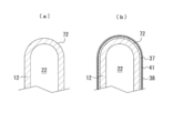
- FIGS. 4A to 4D are schematic views for explaining a procedure for forming a ceramic substrate in the manufacturing process of the module.
- (a) is a partially broken schematic view showing a state before the porous body is formed on the porous body support, and (b) is porous on the porous body support.
- rupture schematic which shows the state after forming a body.
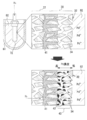
- the principal part expansion schematic which shows the mode before and behind when forming a catalyst metal layer in the manufacturing process of the module.
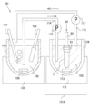
- the schematic which shows the lubricating oil reproduction
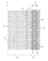
- the SEM photograph which shows the porous body of the state in the same module after formation of a hydrogen separation metal layer and before formation of a catalyst metal layer.
- the catalyst-carrying hydrogen permeable membrane module 11 of the present embodiment shown in FIG. 1 (a) is a device for separating hydrogen from a hydrogen-containing gas G1, which is a raw material gas, and is basically a porous body support.
- the body 12, the dense portion 21, and the catalyst-supporting hydrogen permeable membrane 31 are configured.
- the porous support 12 constituting the hydrogen permeable membrane module 11 is a cylindrical member having an end 14 (open end) having an opening 13 and an end 15 (closed end) having no opening 13. .
- the porous support 12 is composed of a porous ceramic having a property (gas permeability) that allows the hydrogen-containing gas G1 to pass between the inner surface 16 and the outer surface 17.
- the porous support 12 is made of porous yttria-stabilized zirconia (YSZ) having a thickness of about 1 mm to 2 mm and a porosity of about 30% to 50%.
- the hydrogen-containing gas G1 includes, for example, a reformed gas generated by bringing natural gas and water vapor into contact with the catalyst, and pure hydrogen gas is also included.
- the end 14 on the opening side of the porous support 12 is integrally formed with a cylindrical dense portion 21 made of a dense ceramic that is not gas permeable and has higher strength than the porous support 12.
- the dense portion 21 of the present embodiment is configured using dense YSZ having a porosity of approximately 0%.
- the porous substrate 12 and the dense portion 21 constitute a module base, and an internal space 22 is formed inside thereof.
- a metal joint 51 made of a mounting bracket, a pressing bracket, a sealing material, a fixing bracket and the like is screwed into the dense portion 21 located on the proximal end side of the hydrogen permeable membrane module 11.
- the pipe for introducing the hydrogen-containing gas G1 (that is, the gas introduction pipe 52) is connected through the metal joint 51.
- a catalyst-supporting hydrogen permeable membrane 31 is integrally formed so as to cover the entire outer surface 17 across the porous body support 12 and a part of the dense portion 21. That is, it can be understood that the hydrogen permeable membrane 31 is supported by the porous support 12 and the dense portion 21.
- the hydrogen permeable membrane 31 has a front surface 32 and a back surface 33 and is mainly composed of a porous body 35 having a film shape.
- the porous body 35 in the present embodiment is configured using porous YSZ having a thickness of about 20 ⁇ m to 40 ⁇ m and a porosity of about 40% to 60%. Since the porous body 35 has a large number of pores 34 communicating with the front surface 32 and the back surface 33, the porous body 35 has suitable gas and liquid permeability like the porous body support 12.
- the porous body 35 of the present embodiment has a structure in which a second porous layer 38 is integrally formed on a first porous layer 37.
- the hydrogen separation metal layer 41 is formed so as to fill the pores. . Therefore, the hydrogen separation metal layer 41 is completely embedded in the porous body 35 and is not exposed from the surface 32 of the porous body 35. Further, the hydrogen separation metal layer 41 separates hydrogen from the hydrogen-containing gas G1 supplied to the back surface 33 of the porous body 35 and selectively permeates the hydrogen from the back surface 33 side to the front surface 32 side in an atomic state. It has the property of being able to.
- the hydrogen separation metal layer 41 of this embodiment is a PdAg alloy layer whose thickness is set to about 5 ⁇ m to 15 ⁇ m. As will be described later, this PdAg alloy layer is formed by alloying an inner Pd layer formed by electroless plating and an outer Ag layer formed by electrolytic plating.
- a catalyst metal layer 43 is formed on the surface layer portion.
- a catalytic metal layer 43 is not formed on the surface 32 of the porous body 35. Therefore, like the hydrogen separation metal layer 41, the catalyst metal layer 43 is completely embedded in the porous body 35 and is not exposed from the surface 32 of the porous body 35.
- the catalytic metal 42 constituting the catalytic metal layer 43 of the present embodiment Pd alone is used.
- the catalyst metal 42 is basically supported on the inner wall surface of the pore 34 in the surface layer portion in a state where the pore 34 is not filled (that is, the pore 34 is not blocked).
- the catalyst metal layer 43 in the present embodiment has a concentration gradient in which the concentration of the catalyst metal 42 increases as the distance from the front surface 32 to the back surface 33, that is, the closer to the hydrogen separation metal layer 41 in the inner layer. At least a part of the catalyst metal 42 is supported in contact with the hydrogen separation metal layer 41 (see FIGS. 2 and 5).
- a procedure for manufacturing the hydrogen permeable membrane module 11 will be described.
- a module base constituting the hydrogen permeable membrane module 11 is produced by press molding.
- the press molding is performed using a mold 61 as shown in FIG.
- a cylindrical inner hole 63 corresponding to the outer shape of the module base is formed at the axial center of the cylindrical rubber mold 62 of the mold 61.
- a columnar (test tube shape) center pin 64 corresponding to the shape of the internal space 22 is erected at the axial center of the inner hole 63, thereby forming a substantially cylindrical mold hole 65.
- the mold hole 65 of the rubber mold 62 is first filled with YSZ granulated powder, which is a material for forming the dense portion, to form the dense portion forming portion 66 (see FIG. 3A).
- YSZ granulated powder which is a material for forming the porous body support body 12
- a forming portion 67 is formed (see FIG. 3B).
- Organic beads as a pore former are added to this YSZ granulated powder.
- the upper mold 68 is fixed to the upper part of the rubber mold 62.
- a recess 69 having a shape corresponding to the tip of the porous support 12 is formed on the molding surface of the upper mold 68 (see FIG. 3C).
- a porous body support forming portion 67 having the same shape as the porous body support 12 is formed.
- the molded body 71 corresponding to the shape of the module base that is, the shape of the test tube
- the molded body 71 taken out from the rubber mold 62 is degreased and fired to obtain a ceramic sintered body 72 in which the dense portion 21 and the porous body support 12 are integrated (FIG. 4A). )reference).
- a slurry in which YSZ powder is dispersed in an organic solvent is prepared, and the slurry is adhered to the entire outer surface 17 of the porous support 12 in the ceramic fired body by a dip coating method. And it heats and bakes and forms the 1st porous layer 37 which covers the outer surface 17 of the support body 12 made from a porous body.
- the porous body support 12 after the formation of the first porous layer 37 is immersed in the Sn ion solution, and Sn ions are adsorbed on the first porous layer 37.
- the porous support 12 is immersed in a Pd ion solution, and Pd ions are adsorbed by an exchange reaction between Sn ions and Pd ions.
- the porous support 12 is immersed in a reducing agent solution such as a hydrazine solution to reduce Pd ions to form Pd metal nuclei. That is, Pd metal nuclei are attached to the surfaces of the pores 34 of the first porous layer 37.
- the second porous layer 38 is formed on the first porous layer 37 by dip-coating and baking again the slurry in which the YSZ powder is dispersed.
- the porous body 35 having a structure in which the first porous layer 37 and the second porous layer 38 are integrated is formed.
- Pd nuclei inside the porous body 35 are grown by electroless plating to form an electroless plating layer made of Pd.
- the electroless Pd plating solution is supplied from the outer surface 17 side of the porous body 35 in the porous body support 12.
- an electrolytic solution is introduced into the internal space 22 of the porous support 12 and a feeding electrode is inserted into the electrolytic solution.
- the porous support 12 in this state is set in an electrolytic Ag plating solution having a bath temperature of 30 ° C. on which a counter electrode is disposed, and is subjected to constant current electrolytic plating, whereby electrolysis made of Ag on the electroless plating layer.
- a plating layer is formed.
- heat treatment is performed in nitrogen to alloy Pd and Ag to form a PdAg layer as the hydrogen separation metal layer 41 (see FIG. 4B).
- FIG. 7 is an SEM photograph showing the state at this time.
- the catalyst metal layer 43 is formed by the following procedure. First, what prepared the catalyst liquid 82 containing Pd ion (ion of the catalyst metal 42) in the container 81 is prepared, and the said support body 12 made from the porous body after forming the hydrogen separation metal layer 41 is immersed in this. Then, hydrogen is supplied to the internal space 22 of the porous support 12. In this case, the hydrogen supplied to the internal space 22 becomes an atomic state, passes through the hydrogen separation metal layer 41, and is supplied to the catalyst liquid 82 (see FIG. 5). Then, Pd ions in the catalyst solution 82 are reduced, Pd is deposited on the hydrogen separation metal layer 41 and on the inner wall surfaces of the pores 34, and the catalyst metal layer 43 is formed on the surface layer portion. Through the above procedure, the catalyst-supporting hydrogen permeable membrane module 11 of the present embodiment is completed. Hereinafter, examples in which the present embodiment is more specific will be described.
- the hydrogen permeable membrane module 11 of Example was produced in the following procedures.
- the mold 61 described above is prepared, and the rubber mold 62 is filled with YSZ granulated powder, and then filled with YSZ granulated powder with 48% by volume organic beads added as a pore former, followed by press molding.
- a formed body 71 having a test tube shape was formed by the method.
- the molded body 71 to be a module base later is degreased and fired at 1400 ° C. in an air atmosphere, whereby the dense portion 21 and the porous body support 12 are integrated into an outer diameter of 10 mm ⁇ length.
- a 300 mm ceramic sintered body 72 was obtained.
- a slurry in which YSZ powder was dispersed in an organic solvent was prepared, and the slurry was adhered to the entire outer surface 17 of the porous support 12 in the ceramic sintered body 72 by a dip coating method. And it heated at 1200 degreeC and baked and formed the 1st porous layer 37 which covers the outer surface 17 of the support body 12 made from a porous body.
- the porous body support 12 after the formation of the first porous layer 37 was immersed in an Sn ion solution, and Sn ions were adsorbed on the surface of the first porous layer 37. After washing with water, the porous support 12 was immersed in a Pd ion solution, and Pd ions were adsorbed by an exchange reaction between Sn ions and Pd ions.
- the porous support 12 was immersed in a hydrazine solution to reduce Pd ions to form Pd metal nuclei.
- the second porous layer 38 was formed on the first porous layer 37 by dip-coating and baking the slurry in which the YSZ powder was dispersed again. Thereby, the porous body 35 having a structure in which the first porous layer 37 and the second porous layer 38 were integrated was obtained.
- Pd nuclei inside the porous body 35 were grown by an electroless plating method to form an electroless plating layer made of Pd and having a thickness of 3.0 ⁇ m. At this time, the electroless Pd plating solution was supplied from the surface 32 side of the porous body 35 in the porous body support 12.
- a 6.0 mol / L NaCl aqueous solution was introduced as an electrolytic solution into the internal space 22 of the porous support 12.
- the feeding electrode was inserted into the electrolytic solution, and the porous support 12 in this state was set in an electrolytic Ag plating solution (silver nitrate concentration 37 g / L) at a bath temperature of 30 ° C. where the counter electrode was disposed.
- an electrolytic Ag plating solution silver nitrate concentration 37 g / L
- a 1.0 ⁇ m electrolytic plating layer made of Ag was formed on the electroless plating layer.
- heat treatment was performed in nitrogen at 750 ° C. to alloy Pd and Ag, and a 4.0 ⁇ m PdAg layer as the hydrogen separation metal layer 41 was formed.
- a catalyst solution 82 in which palladium chloride powder was dissolved in a 1 N aqueous hydrochloric acid solution so that the Pd concentration was 0.1 mol / L to 10 mol / L was prepared, and a solution in which this was put in a container 81 was prepared.
- the catalyst solution 82 was heated to 40 ° C. to 95 ° C., and the porous support 12 after the formation of the hydrogen separation metal layer 41 was immersed therein.
- the porous support 12 was connected to a hydrogen cylinder, and hydrogen was supplied to the internal space 22 at a pressure of 0.0 MPaG to 0.2 MPaG for 1 second to 60 seconds.
- the atomic hydrogen that has passed through the hydrogen separation metal layer 41 reduces Pd ions in the catalyst liquid 82, and deposits Pd on the hydrogen separation metal layer 41 and on the inner wall surfaces of the pores 34.
- a catalytic metal layer 43 was formed. Thereafter, the supply of hydrogen was stopped, and the surface 32 of the porous body 35 was washed to complete the hydrogen permeable membrane module 11 of the example.
- the lubricating oil regeneration test apparatus 101 includes an oxidation tank 103 that promotes oxidation of the lubricating oil 102 and a reduction processing tank 104 that performs a reduction regeneration process by adding hydrogen to the lubricating oil 102.
- a paraffinic mineral oil blended with an antioxidant is used as the lubricating oil 102.
- “regeneration of lubricating oil” means that the deteriorated (oxidized) antioxidant in the mineral oil is reduced and regenerated.
- the oxidation tank 103 is a round-bottomed container having an opening at the top, and the lower part of the container is set in a heater 105 with a magnetic stirrer.
- a stirrer 106 for stirring the lubricating oil 102 to make it uniform is introduced.
- an air introduction tube 107 and a glass rod 108 wound with a stainless mesh are inserted in the oxidation tank 103.
- the air introduction pipe 107 is for introducing air into the lubricating oil 102 (that is, performing bubbling).
- the glass rod 108 serves as a catalyst for promoting the oxidation of the lubricating oil 102.
- the reduction treatment tank 104 is also a round-bottomed container having an opening in the upper part, and the lower part of this container is set in a heater 112 with a magnetic stirrer.
- a stirring bar 113 for stirring the lubricating oil 102 to make it uniform is introduced.
- the hydrogen permeable membrane module 11 of the embodiment in which the gas introduction pipe 52 is connected via the metal joint 51 is inserted into the reduction treatment tank 104.
- the gas introduction pipe 52 is for introducing the hydrogen-containing gas G1 into the inner space 22 side of the porous support 12 through the open end.
- an oxidation oil recovery pipe 114 for supplying the lubricating oil 102 oxidized in the oxidation tank 103 to the reduction treatment tank 104 is provided.
- a pump 115 is provided for pressure-feeding the gas to the reduction treatment tank 104 side.
- a reclaimed oil recovery pipe 116 for sending the lubricating oil 102 regenerated in the reduction treatment tank 104 from the reduction treatment tank 104 is provided between the oxidation tank 103 and the reduction treatment tank 104.
- a pump 117 that pumps the lubricating oil 102 toward the oxidation tank 103 is provided.
- the structure belonging to the oxidation tank 103 is a “lubricating oil regeneration apparatus 101A” according to the present invention which is an embodiment of the hydrogenation apparatus. Can be grasped.
- a lubricating oil regeneration test was carried out under the following conditions.
- the temperature in the tank was set to 150 ° C. by the heater 105 with a magnetic stirrer, and air was introduced into the lubricating oil 102 at a flow rate of 1 L / min.
- hydrogen was supplied with the pressure of 20 kPaG to the hydrogen permeable membrane module 11 for 25 hours. An investigation was conducted after 25 hours, and it was confirmed that the lubricating oil 102 was reliably reduced and regenerated.
- a metal wear powder deterioration test was performed after the above-mentioned lubricant regeneration test.
- a lubricating oil 102 into which metal wear powder was introduced was prepared, and the hydrogen permeable membrane module 11 of the example was immersed in the lubricating oil 102 and stirred for 24 hours.
- a well-known helium leak test was conducted.
- the hydrogen permeable membrane module 11 was connected to a helium cylinder, and helium was introduced to the inner space 22 side of the porous support 12 through the open end. At that time, the amount of helium leaked to the outside of the module was evaluated with a soap film flow meter.
- the mold 61 described above is prepared, and the rubber mold 62 is filled with YSZ granulated powder, and then filled with YSZ granulated powder with 48% by volume organic beads added as a pore former, followed by press molding.
- a formed body 71 having a test tube shape was formed by the method.
- the molded body 71 to be a module base later is degreased and fired at 1400 ° C. in an air atmosphere, whereby the dense portion 21 and the porous body support 12 are integrated into an outer diameter of 10 mm ⁇ length.
- a 300 mm ceramic sintered body 72 was obtained.
- a slurry in which YSZ powder was dispersed in an organic solvent was prepared, and the slurry was adhered to the entire outer surface 17 of the porous support 12 in the ceramic sintered body 72 by a dip coating method. And it heated at 1200 degreeC and baked and formed the 1st porous layer 37 which covers the outer surface 17 of the support body 12 made from a porous body.
- the porous body support 12 after the formation of the first porous layer 37 was immersed in an Sn ion solution, and Sn ions were adsorbed on the surface of the first porous layer 37. After washing with water, the porous support 12 was immersed in a Pd ion solution, and Pd ions were adsorbed by an exchange reaction between Sn ions and Pd ions.
- the porous support 12 was immersed in a hydrazine solution to reduce Pd ions to form Pd metal nuclei.
- the second porous layer 38 is not formed by dip coating again, and the first porous layer 37 is used as the porous body 35.
- Pd nuclei on the surface of the porous body 35 were grown by an electroless plating method to form an electroless plating layer made of Pd and having a thickness of 8.0 ⁇ m.
- the electroless Pd plating solution was supplied from the surface 32 side of the porous body 35 in the porous body support 12.
- a 6.0 mol / L NaCl aqueous solution was introduced as an electrolytic solution into the internal space 22 of the porous support 12.
- the feeding electrode was inserted into the electrolytic solution, and the porous support 12 in this state was set in an electrolytic Ag plating solution (silver nitrate concentration 37 g / L) at a bath temperature of 30 ° C. where the counter electrode was disposed.
- an electrolytic Ag plating solution silver nitrate concentration 37 g / L
- a constant current electrolytic plating was performed for 2 minutes at a current value of 1.3 A / dm 2 to form a 2.0 ⁇ m electrolytic plating layer made of Ag on the electroless plating layer.
- heat treatment was performed at 750 ° C. in nitrogen to alloy Pd and Ag, and a 10.0 ⁇ m PdAg layer as the hydrogen separation metal layer 41 was formed.
- a catalyst solution 82 in which palladium chloride powder was dissolved in a 1N aqueous hydrochloric acid solution so that the Pd concentration was 0.5 mol / L was prepared, and a catalyst solution 82 was prepared in a container 81.
- the catalyst solution 82 was heated to 80 ° C., and the porous support 12 after the formation of the hydrogen separation metal layer 41 was immersed therein.
- the porous body support 12 was connected to a hydrogen cylinder, and hydrogen was supplied to the internal space 22 at a pressure of 0.05 MPaG for 5 seconds.
- the lubricating oil regeneration test apparatus 101 of the above example was used, and a lubricating oil regeneration test was performed in accordance with the method of the example. As a result, the lubricating oil 102 was reliably reduced even for the hydrogen permeable membrane module of the comparative example. It was confirmed that it was playing.
- a metal wear powder deterioration test (helium leak test) was also conducted in accordance with the method of the example. As a result, the amount of helium leak increased to 150 cc / min and deterioration occurred. Was confirmed. Therefore, it was concluded that the hydrogen permeable membrane module of the comparative example in which the hydrogen separation metal layer 41 and the catalyst metal layer 43 are both exposed at the surface 32 is inferior in durability to the metal wear powder.
- the hydrogen separation metal layer 41 is formed at a predetermined depth in the porous body 35, and the catalyst metal layer 43 is formed on the surface 32 and the hydrogen separation metal layer 41. It is carried by the surface layer part which is the area between the two. For this reason, the hydrogen separation metal layer 41 and the catalyst metal layer 43 are not exposed to the surface 32 of the hydrogen permeable membrane 31. Therefore, even if foreign matter such as metal wear powder is contained in the lubricating oil 102 to be processed, the hydrogen separation metal layer 41 and the catalytic metal layer 43 are not damaged by the foreign matter, and the damage is not caused. Is prevented. Therefore, the durability of the hydrogen permeable membrane module 11 can be improved.
- the catalyst metal layer 43 is formed by supporting the catalyst metal 42 not on the surface 32 of the porous body 35 but on the surface layer portion having a large specific surface area. Therefore, the catalyst metal layer 43 having a large amount of the catalyst metal 42 supported can be obtained.
- the separation distance between the hydrogen separation metal layer 41 and the catalyst metal layer 43 is 0 ⁇ m. Therefore, with respect to the part of the catalyst metal 42, the chance of encountering atomic hydrogen that has passed through the hydrogen separation metal layer 41 is greatly increased. As a result, the reactivity between hydrogen and the object to be processed is further increased, and the hydrogenation reaction can be performed more efficiently.
- the catalyst metal layer 43 has a concentration gradient in which the concentration of the catalyst metal 42 increases from the front surface 32 to the back surface 33. Therefore, even when the loadings are made equal, the proportion of the catalytic metal 42 that encounters atomic hydrogen that has permeated through the hydrogen separation metal layer 41 increases, and the reactivity between hydrogen and the object to be treated is further increased. . Further, since the catalytic metal 42 in the vicinity of the surface 32 of the porous body 35 is reduced, there is an advantage that the catalytic metal layer 43 is hardly damaged by the metal wear powder in the lubricating oil 102.
- the hydrogen permeable membrane module 11 of this example is formed on the outer surface 17 which is the main surface of the porous support 12 with the hydrogen permeable membrane 31 supported. Therefore, the hydrogen permeable membrane 31 is supported by the porous support 12 while the necessary strength is given to the entire module 11. For this reason, it is only necessary to give the hydrogen permeable membrane 31 the necessary minimum strength, and the hydrogen permeable membrane 31 can be made thin.
- the hydrogen separation metal layer 41 is formed by alloying different metals.
- the present invention is not limited to this.
- an electrolytic plating layer made of the same Pd may be formed by electroplating to form a hydrogen separation metal layer.
- the hydrogen separation metal layer 41 made of a PdAg alloy is formed.
- the present invention is not limited to this.
- the hydrogen separation metal layer 41 made of a PdCu alloy, a PdAu alloy, or the like may be formed.
- the catalyst metal layer 43 having a uniform Pd concentration may be formed.
- the porous body is made of stabilized zirconia.
- the hydrogen separation metal layer is a palladium layer or a palladium alloy layer, and the catalyst metal constituting the catalyst metal layer is palladium.
- the hydrogen separation metal layer is a palladium layer or a palladium alloy layer, and the catalyst metal constituting the catalyst metal layer does not contain a metal other than palladium or palladium. Be alloy.
- the hydrogen separation metal layer is a palladium layer or a palladium alloy layer, and the catalyst metal constituting the catalyst metal layer is selected from iron, nickel, platinum, and ruthenium.
- a porous body having a front surface and a back surface, and a large number of pores communicating with the front surface and the back surface, and the pores filled at a predetermined depth position in the porous body
- a hydrogen separation metal layer that is formed in a state and selectively transmits hydrogen in the hydrogen-containing gas flowing from the back surface to the surface, and is supported on a surface layer portion that is a region between the surface and the hydrogen separation metal layer.
- a catalyst-supporting hydrogen permeable membrane comprising a catalyst metal layer made of a catalyst metal, wherein after the formation of the hydrogen separation metal layer, ions of the catalyst metal are formed on the surface side of the hydrogen separation metal layer.
- a catalyst-supporting hydrogen comprising a step of forming the catalyst metal layer by causing the hydrogen-containing gas to flow from the back surface to the surface of the hydrogen separation metal layer.
- Catalyst-supporting hydrogen permeable membrane module 12 ... Porous support 17 ... Outer surface as main surface 31 . Catalyst-supporting hydrogen permeable membrane 32 ... surface 33 ... Back side 34 ... pores 35 ... Porous material 41 ... Hydrogen separation metal layer 42.
- Catalytic metal 43 ... catalytic metal layer 52 ... Gas introduction pipe 101A . Lubricating oil regeneration device as a hydrogenation device 102 ... Lubricating oil as an object to be treated 104 ... Reduction treatment tank as a treatment tank 114 ... Oxidized oil recovery pipe 116 ... Recycled oil recovery pipe
Landscapes
- Chemical & Material Sciences (AREA)
- Chemical Kinetics & Catalysis (AREA)
- Inorganic Chemistry (AREA)
- Engineering & Computer Science (AREA)
- Materials Engineering (AREA)
- Organic Chemistry (AREA)
- Separation Using Semi-Permeable Membranes (AREA)
- Catalysts (AREA)
- Lubricants (AREA)
Abstract
L'invention concerne une membrane perméable à l'hydrogène, portant un catalyseur, qui possède une excellente durabilité de couche métallique de séparation d'hydrogène et de couche métallique de catalyseur, et qui n'est pas sensible à la détérioration de l'efficacité du traitement. Une membrane perméable à l'hydrogène, portant un catalyseur 31, selon la présente invention comprend un corps poreux 35, une couche métallique de séparation d'hydrogène 41 et une couche métallique de catalyseur 43. Le corps poreux 35 possède, intérieurement, une pluralité de pores fins 34 à travers lesquels une surface avant 32 et une surface arrière 33 de celui-ci sont en communication l'une avec l'autre. La couche métallique de séparation d'hydrogène 41 est formée de telle sorte que les pores fins 34 sont remplis par celle-ci à une profondeur prédéterminée dans le corps poreux 35. La couche métallique de séparation d'hydrogène 41 possède sélectivement de l'hydrogène dans un gaz contenant de l'hydrogène qui s'écoule de la surface arrière 33 à la surface avant 32 à travers celle-ci. La couche métallique de catalyseur 43 est composée d'un métal de catalyseur 42 qui est porté par une partie de couche de surface qui est une région positionnée entre la surface avant 32 et la couche métallique de séparation d'hydrogène 41.
Priority Applications (1)
| Application Number | Priority Date | Filing Date | Title |
|---|---|---|---|
| JP2017553195A JPWO2017154582A1 (ja) | 2016-03-09 | 2017-02-22 | 触媒担持型水素透過膜及びその製造方法、触媒担持型水素透過膜モジュール、水素添加装置、潤滑油再生装置 |
Applications Claiming Priority (2)
| Application Number | Priority Date | Filing Date | Title |
|---|---|---|---|
| JP2016-045506 | 2016-03-09 | ||
| JP2016045506 | 2016-03-09 |
Publications (1)
| Publication Number | Publication Date |
|---|---|
| WO2017154582A1 true WO2017154582A1 (fr) | 2017-09-14 |
Family
ID=59790364
Family Applications (1)
| Application Number | Title | Priority Date | Filing Date |
|---|---|---|---|
| PCT/JP2017/006679 Ceased WO2017154582A1 (fr) | 2016-03-09 | 2017-02-22 | Membrane perméable à l'hydrogène portant un catalyseur, son procédé de fabrication, module de membrane perméable à l'hydrogène portant un catalyseur, dispositif d'ajout d'hydrogène et dispositif de régénération d'huile lubrifiante |
Country Status (2)
| Country | Link |
|---|---|
| JP (1) | JPWO2017154582A1 (fr) |
| WO (1) | WO2017154582A1 (fr) |
Families Citing this family (1)
| Publication number | Priority date | Publication date | Assignee | Title |
|---|---|---|---|---|
| JP2024179821A (ja) * | 2023-06-16 | 2024-12-26 | トヨタ自動車株式会社 | 水素分離フィルター |
Citations (7)
| Publication number | Priority date | Publication date | Assignee | Title |
|---|---|---|---|---|
| WO2002064241A1 (fr) * | 2001-02-16 | 2002-08-22 | Sumitomo Electric Industries, Ltd. | Structure permeable a l'hydrogene et procede de fabrication ou de reparation de cette derniere |
| JP2007253152A (ja) * | 2005-07-14 | 2007-10-04 | Daikin Ind Ltd | 水素分離体及び水素製造装置 |
| JP2007301514A (ja) * | 2006-05-12 | 2007-11-22 | National Institute Of Advanced Industrial & Technology | 水素分離材及びその製造方法 |
| JP2009263263A (ja) * | 2008-04-23 | 2009-11-12 | Idemitsu Kosan Co Ltd | 有機化合物の還元方法および還元処理装置 |
| JP2011143335A (ja) * | 2010-01-13 | 2011-07-28 | Ngk Spark Plug Co Ltd | 水素分離装置及び水素分離装置の製造方法 |
| JP2012192349A (ja) * | 2011-03-16 | 2012-10-11 | Sumitomo Electric Ind Ltd | ガス処理システム |
| JP2015205788A (ja) * | 2014-04-18 | 2015-11-19 | 東京瓦斯株式会社 | 水素製造装置、並びに水素生成触媒及びその製造方法 |
Family Cites Families (2)
| Publication number | Priority date | Publication date | Assignee | Title |
|---|---|---|---|---|
| KR102213238B1 (ko) * | 2013-12-06 | 2021-02-05 | 동의대학교 산학협력단 | 반투막 및 그 제조 방법 |
| JP6208067B2 (ja) * | 2014-03-31 | 2017-10-04 | 公益財団法人地球環境産業技術研究機構 | 多孔質基材の内部に薄膜化した金属充填層を有する複合体の製造方法および複合体 |
-
2017
- 2017-02-22 WO PCT/JP2017/006679 patent/WO2017154582A1/fr not_active Ceased
- 2017-02-22 JP JP2017553195A patent/JPWO2017154582A1/ja active Pending
Patent Citations (7)
| Publication number | Priority date | Publication date | Assignee | Title |
|---|---|---|---|---|
| WO2002064241A1 (fr) * | 2001-02-16 | 2002-08-22 | Sumitomo Electric Industries, Ltd. | Structure permeable a l'hydrogene et procede de fabrication ou de reparation de cette derniere |
| JP2007253152A (ja) * | 2005-07-14 | 2007-10-04 | Daikin Ind Ltd | 水素分離体及び水素製造装置 |
| JP2007301514A (ja) * | 2006-05-12 | 2007-11-22 | National Institute Of Advanced Industrial & Technology | 水素分離材及びその製造方法 |
| JP2009263263A (ja) * | 2008-04-23 | 2009-11-12 | Idemitsu Kosan Co Ltd | 有機化合物の還元方法および還元処理装置 |
| JP2011143335A (ja) * | 2010-01-13 | 2011-07-28 | Ngk Spark Plug Co Ltd | 水素分離装置及び水素分離装置の製造方法 |
| JP2012192349A (ja) * | 2011-03-16 | 2012-10-11 | Sumitomo Electric Ind Ltd | ガス処理システム |
| JP2015205788A (ja) * | 2014-04-18 | 2015-11-19 | 東京瓦斯株式会社 | 水素製造装置、並びに水素生成触媒及びその製造方法 |
Also Published As
| Publication number | Publication date |
|---|---|
| JPWO2017154582A1 (ja) | 2019-01-17 |
Similar Documents
| Publication | Publication Date | Title |
|---|---|---|
| US8366805B2 (en) | Composite structures with porous anodic oxide layers and methods of fabrication | |
| JP2009195884A (ja) | 電解水生成装置 | |
| US20250345769A1 (en) | Systems and methods for chemical catalytic processing | |
| JP2000234193A (ja) | 電解用陰極及びこの陰極を具備した電解槽 | |
| JP2009022843A (ja) | 高耐久性水素分離膜及びその製造方法 | |
| JP6208067B2 (ja) | 多孔質基材の内部に薄膜化した金属充填層を有する複合体の製造方法および複合体 | |
| JP4753180B2 (ja) | 水素分離材及びその製造方法 | |
| JP6219625B2 (ja) | 水素分離体及びその製造方法 | |
| JP5888188B2 (ja) | 水素分離体 | |
| JP6668115B2 (ja) | アンモニア製造装置、NOx浄化装置 | |
| JPWO2017154582A1 (ja) | 触媒担持型水素透過膜及びその製造方法、触媒担持型水素透過膜モジュール、水素添加装置、潤滑油再生装置 | |
| JP5253369B2 (ja) | 複合体の製造方法 | |
| DE102011079858A1 (de) | Reaktor zur Freisetzung von Wasserstoff aus flüssigen Verbindungen | |
| JP5155343B2 (ja) | 水素分離装置及び水素分離装置の製造方法 | |
| JP6358839B2 (ja) | 水素製造装置及びその製造方法 | |
| US20140170328A1 (en) | Electroless plating of ruthenium and ruthenium-plated products | |
| JP6561334B2 (ja) | 水素分離膜の製造方法 | |
| JP2007283184A (ja) | 水素分離薄膜及びその製造方法。 | |
| JP4893992B2 (ja) | 水素分離複合体及びその製造方法 | |
| JP5897976B2 (ja) | 水素分離装置の製造方法 | |
| JP2007253152A (ja) | 水素分離体及び水素製造装置 | |
| JP6199657B2 (ja) | 水素分離体及びその製造方法 | |
| JP3897052B2 (ja) | 水素分離体、水素製造装置、水素分離体の製造方法及び水素分離体の製造装置 | |
| JP5311536B2 (ja) | Pd−Agの同時メッキによる水素分離用薄膜の作製方法 | |
| JP2006314876A (ja) | 水素分離装置 |
Legal Events
| Date | Code | Title | Description |
|---|---|---|---|
| ENP | Entry into the national phase |
Ref document number: 2017553195 Country of ref document: JP Kind code of ref document: A |
|
| NENP | Non-entry into the national phase |
Ref country code: DE |
|
| 121 | Ep: the epo has been informed by wipo that ep was designated in this application |
Ref document number: 17762923 Country of ref document: EP Kind code of ref document: A1 |
|
| 122 | Ep: pct application non-entry in european phase |
Ref document number: 17762923 Country of ref document: EP Kind code of ref document: A1 |