WO2017154603A1 - Unité à évaporateurs - Google Patents
Unité à évaporateurs Download PDFInfo
- Publication number
- WO2017154603A1 WO2017154603A1 PCT/JP2017/006966 JP2017006966W WO2017154603A1 WO 2017154603 A1 WO2017154603 A1 WO 2017154603A1 JP 2017006966 W JP2017006966 W JP 2017006966W WO 2017154603 A1 WO2017154603 A1 WO 2017154603A1
- Authority
- WO
- WIPO (PCT)
- Prior art keywords
- refrigerant
- gas
- liquid
- evaporator
- unit
- Prior art date
- Legal status (The legal status is an assumption and is not a legal conclusion. Google has not performed a legal analysis and makes no representation as to the accuracy of the status listed.)
- Ceased
Links
Images


Classifications
-
- F—MECHANICAL ENGINEERING; LIGHTING; HEATING; WEAPONS; BLASTING
- F25—REFRIGERATION OR COOLING; COMBINED HEATING AND REFRIGERATION SYSTEMS; HEAT PUMP SYSTEMS; MANUFACTURE OR STORAGE OF ICE; LIQUEFACTION SOLIDIFICATION OF GASES
- F25B—REFRIGERATION MACHINES, PLANTS OR SYSTEMS; COMBINED HEATING AND REFRIGERATION SYSTEMS; HEAT PUMP SYSTEMS
- F25B1/00—Compression machines, plants or systems with non-reversible cycle
-
- F—MECHANICAL ENGINEERING; LIGHTING; HEATING; WEAPONS; BLASTING
- F25—REFRIGERATION OR COOLING; COMBINED HEATING AND REFRIGERATION SYSTEMS; HEAT PUMP SYSTEMS; MANUFACTURE OR STORAGE OF ICE; LIQUEFACTION SOLIDIFICATION OF GASES
- F25B—REFRIGERATION MACHINES, PLANTS OR SYSTEMS; COMBINED HEATING AND REFRIGERATION SYSTEMS; HEAT PUMP SYSTEMS
- F25B39/00—Evaporators; Condensers
- F25B39/02—Evaporators
-
- F—MECHANICAL ENGINEERING; LIGHTING; HEATING; WEAPONS; BLASTING
- F25—REFRIGERATION OR COOLING; COMBINED HEATING AND REFRIGERATION SYSTEMS; HEAT PUMP SYSTEMS; MANUFACTURE OR STORAGE OF ICE; LIQUEFACTION SOLIDIFICATION OF GASES
- F25B—REFRIGERATION MACHINES, PLANTS OR SYSTEMS; COMBINED HEATING AND REFRIGERATION SYSTEMS; HEAT PUMP SYSTEMS
- F25B43/00—Arrangements for separating or purifying gases or liquids; Arrangements for vaporising the residuum of liquid refrigerant, e.g. by heat
Definitions
- This disclosure relates to an evaporator unit used in an ejector refrigeration cycle.
- Patent Document 1 discloses an evaporator unit applied to an ejector refrigeration cycle.
- the evaporator unit of Patent Document 1 includes a branching portion that branches the refrigerant flow, an ejector that performs a refrigerant decompression function, and an evaporator that evaporates the refrigerant by exchanging heat between the refrigerant and air.
- the branch part, the ejector, and the evaporator are integrated (unitized).
- the evaporator unit of Patent Document 1 includes a centrifugal gas-liquid separation part formed in a cylindrical shape as a branch part. Then, a swirl flow is generated in the refrigerant that has flowed out of the radiator in the gas-liquid separation unit, and the gas-liquid two-phase refrigerant around the central axis is caused to flow into the nozzle portion of the ejector. Further, liquid phase refrigerant that is unevenly distributed on the outer peripheral side of the gas-liquid separation unit is caused to flow into an orifice formed on the outer peripheral side surface of the gas-liquid separation unit.
- the evaporator of the evaporator unit of Patent Document 1 includes two heat exchange units, an outflow side heat exchange unit that evaporates the refrigerant that has flowed out of the ejector, and a suction side heat exchange unit that evaporates the refrigerant decompressed by the orifice. It is divided into. Then, the air is efficiently cooled by evaporating the refrigerant in different temperature zones in the two heat exchange units and sequentially cooling the air.
- the cooling capacity of the evaporator unit as a whole can be improved by allowing a refrigerant with low dryness to flow into the suction side heat exchange section where the refrigerant evaporation temperature is low. Therefore, in the evaporator unit of Patent Document 1, a partition wall that prevents the liquid-phase refrigerant from flowing into the nozzle portion is arranged in the gas-liquid separation unit so that the liquid-phase refrigerant can easily flow into the orifice. The cooling capacity of the entire unit is being improved.
- the liquid-phase refrigerant film that is, the liquid film formed on the outer peripheral side in the gas-liquid separation unit becomes thin.
- the liquid phase refrigerant not only the liquid phase refrigerant but also the gas phase refrigerant flows into the orifice.
- a refrigerant with low dryness cannot be allowed to flow into the suction side heat exchanging section, and the cooling capacity of the entire evaporator unit is reduced.
- an object of the present disclosure is to provide an evaporator unit capable of exhibiting sufficient cooling capacity regardless of load fluctuation of an ejector refrigeration cycle.
- the evaporator unit of the present disclosure includes a gas-liquid separation unit, a liquid storage unit, an ejector, a decompression device, and an evaporator.
- the gas-liquid separation unit separates the refrigerant into a gas phase refrigerant and a liquid phase refrigerant.
- the liquid storage unit stores the liquid phase refrigerant.
- the ejector has a body part in which a nozzle part, a refrigerant suction port, and a pressure raising part are formed. The nozzle portion depressurizes the refrigerant including the gas phase refrigerant.
- the refrigerant suction port sucks the refrigerant as the suction refrigerant by the suction action of the high-speed jet refrigerant jetted from the nozzle portion.
- the pressure increasing unit increases the pressure by mixing the injected refrigerant and the suction refrigerant.
- the decompression device decompresses the liquid-phase refrigerant that has flowed out of the liquid storage unit.
- the evaporator has an outflow side heat exchange part and a suction side heat exchange part.
- the outflow side heat exchange unit evaporates the refrigerant that has flowed out of the pressure increasing unit.
- the suction side heat exchange unit evaporates the refrigerant decompressed by the decompression device and causes the refrigerant to flow into the refrigerant suction port.
- the liquid-phase refrigerant stored in the liquid storage part can be caused to flow into the decompression device regardless of the load fluctuation of the ejector refrigeration cycle. Therefore, the refrigerant having a relatively low dryness can surely flow into the suction side heat exchanging section, and the evaporator unit can exhibit high cooling performance.
- the gas-liquid two-phase refrigerant containing the gas-phase refrigerant separated by the gas-liquid separation part can be flowed into the nozzle part of the ejector, the amount of energy recovered by the ejector can be increased. As a result, the boosting ability of the ejector can be improved, and the coefficient of performance (COP) of the ejector refrigeration cycle can be improved.
- FIG. 3 is a schematic cross-sectional view taken along line III-III in FIG. 2. It is a typical perspective view of the gas-liquid separation part and liquid storage part of 1st Embodiment. It is typical sectional drawing which shows the inside of a gas-liquid separation part at the time of a gaseous-phase refrigerant
- the first embodiment will be described below with reference to FIGS.
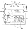
- the evaporator unit 30 of the present embodiment is applied to a vapor compression refrigeration cycle apparatus including an ejector, that is, an ejector refrigeration cycle 10 as shown in the overall configuration diagram of FIG. Further, the ejector refrigeration cycle 10 is applied to a vehicle air conditioner, and cools air (air blown) that is blown into a vehicle interior that is a space to be cooled.
- an HFO refrigerant (specifically, R1234yf) is adopted as a refrigerant circulating in the ejector refrigeration cycle 10.
- the ejector refrigeration cycle 10 constitutes a subcritical refrigeration cycle in which the high-pressure side refrigerant pressure does not exceed the critical pressure of the refrigerant.
- This refrigerant is mixed with refrigerating machine oil for lubricating the compressor 11, and a part of the refrigerating machine oil circulates in the cycle together with the refrigerant.
- the compressor 11 sucks the refrigerant and compresses and discharges it until it becomes a high-pressure refrigerant.
- the compressor 11 is disposed in an engine room together with an engine (internal combustion engine) that outputs a driving force for vehicle travel.
- the compressor 11 is an engine-driven compressor that is driven by a rotational driving force output from the engine via a pulley, a belt, and the like.
- the compressor 11 is a swash plate type variable displacement compressor configured to be able to adjust the refrigerant discharge capacity by changing the discharge capacity.
- the compressor 11 has a discharge capacity control valve (not shown) for changing the discharge capacity.
- the operation of the discharge capacity control valve is controlled by a control current output from an air conditioning control device to be described later.
- the refrigerant inlet of the condenser 12 a of the radiator 12 is connected to the discharge port of the compressor 11.
- the radiator 12 is a heat exchanger that radiates and cools the high-pressure refrigerant by exchanging heat between the high-pressure refrigerant discharged from the compressor 11 and air outside the vehicle compartment (outside air) blown by the cooling fan 12d.
- the radiator 12 is arranged on the vehicle front side in the engine room.
- the radiator 12 of the present embodiment is a so-called subcooled condenser having a condensing unit 12a, a receiver unit 12b, and a supercooling unit 12c.
- the condensing unit 12a is a heat exchange unit for condensation that exchanges heat between the high-pressure gas-phase refrigerant discharged from the compressor 11 and the outside air blown from the cooling fan 12d, and dissipates the high-pressure gas-phase refrigerant to condense.
- the receiver unit 12b is a gas-liquid separator that separates the refrigerant flowing out of the condensing unit 12a into a gas phase refrigerant and a liquid phase refrigerant.
- the supercooling unit 12c is a heat exchange unit for supercooling that heat-exchanges the liquid refrigerant separated by the receiver unit 12b and the outside air blown from the cooling fan 12d to supercool the liquid refrigerant.
- the cooling fan 12d is an electric blower, and the number of rotations of the cooling fan 12d, in other words, the amount of air blown by the cooling fan 12d is controlled by a control voltage output from the air conditioning control device.
- the inlet of the temperature type expansion valve 13 is connected to the refrigerant outlet of the supercooling part 12 c of the radiator 12.
- the temperature type expansion valve 13 is a flow rate adjusting device that reduces the pressure of the high-pressure liquid-phase refrigerant that has flowed out from the supercooling unit 12c of the radiator 12 until it becomes an intermediate-pressure refrigerant and adjusts the circulating refrigerant flow rate that circulates in the cycle. Furthermore, the temperature type expansion valve 13 of the present embodiment adjusts the circulating refrigerant flow rate so that the superheat degree of the evaporator unit 30 outlet side refrigerant approaches a predetermined reference superheat degree.
- the temperature type expansion valve 13 includes a temperature sensing unit having a displacement member (diaphragm) that is displaced according to the temperature and pressure of the refrigerant flowing out of the evaporator unit 30, for example.
- the valve opening degree of the temperature type expansion valve 13 in other words, the flow rate of the refrigerant passing through the temperature type expansion valve 13 is based on the degree of superheat of the refrigerant on the outlet side of the evaporator unit 30 according to the displacement of the displacement member. It is adjusted by a mechanical mechanism to approach the degree of superheat.
- the refrigerant inlet 22 a of the evaporator unit 30 is connected to the outlet of the temperature type expansion valve 13.
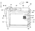
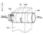
- the cycle constituent devices surrounded by the one-dot chain line in FIG. 1 are integrated (that is, unitized) as shown in the schematic external perspective view of FIG.
- the evaporator unit 30 is integrated (unitized) with each other, the joint part 22, the gas-liquid separation part 14, the liquid storage part 15, the ejector 16, the windward evaporator 17, the leeward evaporator. 18, a capillary tube 19, and a heat exchange passage 21.
- the detailed configuration of the evaporator unit 30 will be described with reference to FIGS. 2 to 8 indicate the up and down directions when the evaporator unit 30 is mounted on the vehicle.
- the joint portion 22 is a connection member to which the outlet of the temperature type expansion valve 13 and the suction port of the compressor 11 are connected when the evaporator unit 30 is applied to the ejector type refrigeration cycle 10.
- the joint portion 22 is formed of a block member made of metal (in this embodiment, made of an aluminum alloy).
- the joint portion 22 is formed with a refrigerant inlet 22a and a refrigerant outlet 22b.
- the refrigerant inlet 22 a is an inlet through which the intermediate pressure refrigerant decompressed by the temperature type expansion valve 13 flows into the evaporator unit 30.
- the refrigerant outlet 22 b is an outlet through which the refrigerant in the evaporator unit 30 flows out to the suction port of the compressor 11.
- the refrigerant outlet 22b is an outlet through which the refrigerant flows out of the evaporator unit 30.
- the refrigerant in the evaporator unit 30 flows out of the evaporator unit 30 through the refrigerant outlet 22 b and flows into the suction port of the compressor 11.
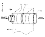
- FIG. 3 is a schematic enlarged cross-sectional view of the introduction passage 22c as seen from the axial direction of the gas-liquid separation unit 14.
- the gas-liquid separation part 14 is made of the same metal as the joint part 22 and is formed of a cylindrical member extending in a substantially horizontal direction.
- the gas-liquid separation unit 14 of the present embodiment turns the refrigerant flowing into the cylindrical internal space around the central axis and separates the refrigerant into a gas phase refrigerant and a liquid phase refrigerant by the action of centrifugal force. This is a gas-liquid separation unit using a centrifugal separation method.
- the shape of the introduction passage 22c in the joint portion 22 is a curved shape as shown in FIG.
- the refrigerant flowing into the gas-liquid separation unit 14 flows in the circumferential direction along the outer peripheral wall surface of the internal space of the gas-liquid separation unit 14, and the refrigerant in the gas-liquid separation unit 14 is swirled.
- an inlet portion 14 a for allowing the refrigerant to flow into the internal space from the refrigerant inlet 22 a of the joint portion 22 is formed at one axial end portion of the gas-liquid branching portion 14.
- an outlet portion 14 b through which the refrigerant flows out from the gas-liquid branching portion 14 is formed at the other axial end portion of the gas-liquid separating portion 14.
- the gas-liquid separation part 14 of this embodiment can also be expressed as being formed by two cylindrical members having the same diameter and arranged coaxially with each other.
- the gas-liquid separation unit 14 of the present embodiment is a centrifugal separation method
- a liquid phase refrigerant having a density higher than that of the gas phase refrigerant is unevenly distributed on the outer peripheral side of the internal space by the action of the centrifugal force.
- the slit hole 14c is opened in a shape extending in the circumferential direction, the liquid-phase refrigerant is likely to flow preferentially out of the gas-phase refrigerant from the slit hole 14c.
- the slit hole 14c is a liquid phase refrigerant outlet through which the separated liquid phase refrigerant flows out.
- the liquid-phase refrigerant can be preferentially discharged from the gas-phase refrigerant through the slit hole 14c, the remaining refrigerant in a gas-liquid two-phase state having a relatively high dryness can be discharged from the outlet portion 14b. . That is, in the gas-liquid separation unit 14 of the present embodiment, not only can the flow of the refrigerant decompressed by the temperature type expansion valve 13 be branched, but also the dryness of each of the branched refrigerants can be adjusted. . The dryness is the gas-liquid ratio between the gas-phase refrigerant and the liquid-phase refrigerant.
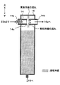
- the gas-liquid separation unit 14 is disposed so as to penetrate the liquid storage unit 15 indicated by a two-dot chain line in FIG. More specifically, the gas-liquid separation unit 14 has an axial end portion (that is, the inlet portion 14a) and a shaft in a state where the axial central portion where the slit hole 14c is formed is accommodated in the liquid storage portion 15. The other end portion in the direction (that is, the outlet portion 14 b) is fixed to the liquid storage portion 15.
- the liquid storage unit 15 is a refrigerant container that stores the liquid-phase refrigerant separated by the gas-liquid separation unit 14 and flowing out from the slit hole 14c.
- the liquid storage part 15 is formed of a bottomed cylindrical member made of the same metal as the joint part 22. Furthermore, as shown in FIGS. 2 and 7, the liquid storage unit 15 is formed in a shape extending in a substantially vertical direction along the outer surfaces of the windward evaporator 17 and the leeward evaporator 18.
- the liquid storage unit 15 is formed with a liquid phase refrigerant outlet through which the stored liquid phase refrigerant flows out.
- An inlet of a suction side heat exchange unit 18b of the leeward evaporator 18 to be described later is formed at the liquid phase refrigerant outlet. It is connected.
- the refrigerant flowing from the gas-liquid separation unit 14 to the liquid storage unit 15 through the slit hole 14c may include not only a liquid phase refrigerant but also a gas phase refrigerant.
- the gas-phase refrigerant that has flowed into the liquid storage unit 15 through the slit hole 14c or the gas-phase refrigerant that originally remained in the liquid storage unit 15 is indicated by the broken line arrows in FIG. It returns to the gas-liquid separation part 14 through the slit hole 14c.
- the gas-phase refrigerant that has flowed into the gas-liquid separator 14 flows into the nozzle portion 16a of the ejector 16 described later via the outlet portion 14b.
- the opening area of the slit hole 14c of this embodiment not only allows the liquid-phase refrigerant to flow from the gas-liquid separation unit 14 to the liquid storage unit 15, but also stores excess gas-phase refrigerant in the liquid storage unit 15. It is set so that it can be returned from the unit 15 to the gas-liquid separation unit 14.
- the liquid-phase refrigerant is indicated by point hatching for clarification of illustration.
- the liquid storage unit 15 becomes full as shown in FIG. Then, a gas-liquid two-phase refrigerant in which the gas-phase refrigerant separated by the gas-liquid separator 14 and the excess liquid-phase refrigerant are mixed flows out from the outlet 14 b of the gas-liquid separator 14.
- an inlet of a capillary tube 19 is connected to the refrigerant outlet of the liquid storage unit 15 as a decompression device that depressurizes the liquid-phase refrigerant flowing out of the liquid storage unit 15.
- the outlet of the capillary tube 19 is connected to the inlet of the suction side heat exchange unit 18 b of the leeward evaporator 18.
- the outlet 14b of the gas-liquid separator 14 is connected to the inlet of the nozzle 16a of the ejector 16.
- the ejector 16 is a refrigerant decompression device that decompresses the refrigerant that has flowed out from the outlet 14b of the gas-liquid separation unit 14 until it becomes a low-pressure refrigerant.
- the ejector 16 is a refrigerant circulation device that sucks and circulates the refrigerant by the suction action of the refrigerant flow injected at a high speed.
- the ejector 16 has a nozzle portion 16a and a body portion 16b.
- the nozzle portion 16a is formed of a metal cylindrical member that gradually tapers in the refrigerant flow direction.
- the nozzle portion 16a is made of stainless steel.
- the nozzle portion 16a isentropically depressurized in the refrigerant passage (that is, the throttle passage) formed inside.
- a throat portion having the smallest refrigerant passage area and a divergent portion in which the refrigerant passage area gradually increases from the throat toward the refrigerant injection port for injecting the refrigerant are formed.
- the nozzle part 16a of this embodiment is what is called a Laval nozzle.
- the nozzle portion 16a is set so that the flow rate of the injected refrigerant injected from the refrigerant injection port is equal to or higher than the sonic speed during normal operation of the ejector refrigeration cycle 10.
- the nozzle portion 16a may be a tapered nozzle.
- the body portion 16b is formed of a cylindrical member made of the same metal as the joint portion 22 and the like.
- the body portion 16b is a fixing member that forms an outer shell of the ejector 16 and supports and fixes the nozzle portion 16a therein. More specifically, the nozzle portion 16a is fixed by press-fitting so as to be accommodated inside one end portion in the longitudinal direction of the body portion 16b. Therefore, the refrigerant does not leak from the fixed portion (press-fit portion) between the nozzle portion 16a and the body portion 16b.
- a refrigerant suction port 16c provided in a portion corresponding to the outer peripheral side of the nozzle portion 16a in the outer peripheral surface of the body portion 16b is provided so as to penetrate the inside and the outside and communicate with the refrigerant injection port of the nozzle portion 16a. Is formed.
- the refrigerant suction port 16c is a through hole that sucks the refrigerant that has flowed out from the suction side heat exchange unit 18b of the leeward evaporator 18 described later into the ejector 16 by the suction action of the jet refrigerant injected from the nozzle unit 16a. is there.
- the suction passage is a refrigerant passage that guides the suction refrigerant sucked from the refrigerant suction port 16c to the refrigerant injection port of the nozzle portion 16a.
- the diffuser portion 16d is a pressure increasing portion that increases the pressure by mixing the suction refrigerant and the injection refrigerant that have flowed into the ejector 16 from the refrigerant suction port 16c through the suction passage.
- the suction passage is formed by a space between the outer peripheral side around the tapered tip of the nozzle portion 16a and the inner peripheral side of the body portion 16b, and the refrigerant passage area of the suction passage is directed toward the refrigerant flow direction. It is gradually shrinking. Thereby, the flow rate of the suction refrigerant flowing through the suction passage is gradually increased, and the energy loss (mixing loss) when the suction refrigerant and the injection refrigerant are mixed in the diffuser portion 16d is reduced.
- the diffuser portion 16d is disposed so as to be continuous with the outlet of the suction passage, and is formed so that the refrigerant passage area gradually increases. Thereby, the diffuser part 16d decelerates the flow velocity while mixing the injection refrigerant and the suction refrigerant, and increases the pressure of the mixed refrigerant of the injection refrigerant and the suction refrigerant. That is, the diffuser part 16d converts the velocity energy of the mixed refrigerant into pressure energy.
- the cross-sectional shape of the inner peripheral wall surface of the body portion 16b forming the diffuser portion 16d of the present embodiment is a shape obtained by combining a plurality of curves. And since the degree of spread of the refrigerant passage cross-sectional area of the diffuser portion 16d gradually increases in the refrigerant flow direction and then decreases again, the refrigerant can be increased in an isentropic manner.
- a branch portion 20 that branches the refrigerant flow is connected to the outlet of the diffuser portion 16d.
- the branch unit 20 branches the flow of the refrigerant flowing out from the diffuser unit 16d into two refrigerant flows, and causes one refrigerant flow to flow into the first outflow side heat exchange unit 17a of the windward evaporator 17, and the other refrigerant The flow is caused to flow into the second outflow side heat exchange unit 18 a of the leeward evaporator 18.
- the windward side evaporator 17 and the leeward side evaporator 18 both exchange heat between the air blown from the blower fan 30a toward the vehicle interior and the refrigerant, and evaporate the refrigerant to exhibit the endothermic effect. It is the evaporator which cools.
- the windward evaporator 17 is divided into a first outflow side heat exchange section 17a and a third outflow side heat exchange section 17b.
- the leeward evaporator 18 is divided into a second outflow side heat exchange unit 18a and a suction side heat exchange unit 18b.
- the 1st outflow side heat exchange part 17a, the 2nd outflow side heat exchange part 18a, and the 3rd outflow side heat exchange part 17b evaporate the refrigerant which flowed out from diffuser part 16d of ejector 16.
- the suction side heat exchange unit 18 b evaporates the refrigerant decompressed by the capillary tube 19 and causes the refrigerant to flow into the refrigerant suction port 16 c of the ejector 16.
- the first, second, and third outflow side heat exchange units 17a, 18a, and 17b are all heat exchange units that evaporate the refrigerant that has flowed out of the diffuser unit 16d. Therefore, in the following description, these three heat exchange units may be collectively referred to as an outflow side heat exchange unit.
- the windward evaporator 17 is provided with a first outflow side heat exchange unit 17a and a third outflow side heat exchange unit 17b.
- the leeward evaporator 18 is provided with a second outflow side heat exchange unit 18a and a suction side heat exchange unit 18b.
- the first outflow side heat exchanging part 17a is a heat exchanging part that evaporates one of the two refrigerant flows branched by the branching part 20.
- the 3rd outflow side heat exchange part 17b is a heat exchange part which evaporates the refrigerant
- the second outflow side heat exchange section 18a is a heat exchange section that evaporates the other of the two refrigerant flows branched by the branch section 20.
- the suction side heat exchange unit 18 b is a heat exchange unit that evaporates the refrigerant decompressed by the capillary tube 19.
- a refrigerant suction port 16c of the ejector 16 is connected to the refrigerant outlet of the suction side heat exchange unit 18b.
- the windward side evaporator 17 and the leeward side evaporator 18 are arranged in series with respect to the flow direction of the air blown into the vehicle interior, and the leeward side evaporator 18 is air to the windward side evaporator 17. It is arranged leeward in the flow direction.
- first outflow side heat exchanging portion 17a and the second outflow side heat exchanging portion 18a are arranged so that at least a part thereof is polymerized when viewed from the air flow direction.
- inhalation side heat exchange part 18b are arrange
- the blower fan 30a is an electric blower, and the rotation speed of the blower fan 30a, in other words, the amount of air blown by the blower fan 30a is controlled by a control voltage output from the air conditioning control device.
- the inlet of the heat exchange passage 21 is connected to the refrigerant outlet of the third outflow side heat exchange section 17b of the windward evaporator 17.
- the heat exchanging passage 21 is a refrigerant passage for exchanging heat between the refrigerant flowing out from the third outflow side heat exchanging portion 17 b and the liquid phase refrigerant in the liquid storage portion 15.
- the heat exchange passage 21 is formed of a bottomed cylindrical member made of the same metal as the joint portion 22 and the like.
- the heat exchange passage 21 is formed in a shape extending in a substantially vertical direction along the outer surfaces of the windward evaporator 17 and the leeward evaporator 18. Furthermore, the heat exchange passage 21 is adjacent to the liquid storage section 15 so that heat exchange between the refrigerant flowing through the heat exchange passage 21 and the liquid phase refrigerant stored in the liquid storage section 15 is possible. Has been placed.
- the outlet of the heat exchange passage 21 is connected to a refrigerant outlet 22 b provided in the joint portion 22. Further, the inlet of the compressor 11 is connected to the refrigerant outlet 22 b of the joint portion 22.
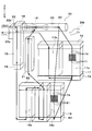
- the windward side evaporator 17 and the leeward side evaporator 18 of this embodiment are comprised with what is called a tank and tube type heat exchanger. Therefore, for example, the leeward evaporator 18 includes a plurality of leeward tubes 81, a pair of leeward tanks 82 and 83, as shown in FIGS.
- the leeward side tube 81 is a refrigerant tube through which the refrigerant evaporated by the leeward side evaporator 18 or the refrigerant evaporated by the leeward side evaporator 18 is circulated.
- the leeward side tube 81 is formed of a metal having excellent heat conductivity.
- the leeward side tube 81 is formed of the same aluminum alloy as the body portion 16b of the ejector 16 and the like.
- the leeward side tube 81 is a flat tube having a flat shape in a cross section perpendicular to the flow direction of the refrigerant flowing through the inside.
- the flow direction of the refrigerant flowing inside the leeward side tube 81 is the longitudinal direction of the leeward side tube 81.
- Each of the leeward side tubes 81 is laminated and arranged with a certain interval so that the flat surfaces (flat surfaces) of the outer surfaces are parallel to each other.
- an air passage is formed between the adjacent leeward side tubes 81 through which the air blown into the vehicle compartment flows. That is, in the leeward side evaporator 18, the heat exchange part (heat exchange core part) which heat-exchanges a refrigerant
- fins 74 that promote heat exchange between the refrigerant and the air are arranged in the air passage formed between the adjacent leeward tubes 81.
- the fins 74 are corrugated fins formed by bending a thin plate material of the same material as the leeward side tube 81 into a wave shape. In FIGS. 2 and 7, only a part of the leeward side tube 81, the leeward side tube 71, and the fins 74 are illustrated for clarity of illustration.
- the pair of leeward tanks 82 and 83 are refrigerant tanks that are connected to both ends of the plurality of leeward tubes 81 and collect or distribute the refrigerant flowing through the leeward tubes 81.
- the leeward tank disposed on the upper side in the vertical direction is referred to as an upper leeward tank 82
- the tank disposed on the lower side in the vertical direction is referred to as a lower leeward tank 83.
- the leeward tanks 82 and 83 are formed of a bottomed cylindrical member made of the same material as the leeward tube 81.
- the leeward tanks 82 and 83 are formed in a shape extending in the stacking direction of the leeward tubes 81.
- a plurality of separators that divide the internal space are disposed in the internal space of the leeward tanks 82 and 83.
- the basic configuration of the windward evaporator 17 is the same as that of the windward evaporator 18. Accordingly, the windward evaporator 17 includes a plurality of windward tubes 71, a pair of windward tanks, fins 74, and the like, as shown in FIG. Specifically, the pair of windward tanks are an upper windward tank 72 disposed on the upper side in the vertical direction and a lower windward tank 73 disposed on the lower side in the vertical direction. Each of the upper windward tank 72 and the lower windward tank 73 has an internal space that is partitioned by a plurality of separators.
- At least a part of the upper leeward tank 72 of the leeward evaporator 17 and the upper leeward tank 82 of the leeward evaporator 18 are formed of the same member. Further, at least part of the lower leeward tank 73 and the lower leeward tank 83 are formed of the same member.
- the ejector 16 is accommodated in the storage tank 23.
- the storage tank 23 is made of the same material as the ejector 16, the upper windward tank 72, and the upper windward tank 82.
- the storage tank 23 is formed of a bottomed cylindrical member extending in parallel with the longitudinal direction of the upper windward tank 72 and the upper windward tank 82.
- the storage tank 23 is disposed between the upper windward tank 72 and the upper leeward tank 82 so as to contact both the upper windward tank 72 and the upper leeward tank 82.
- the liquid storage unit 15 is disposed so as to contact the side surface on one end side of the leeward evaporator 18.
- the side surface on one end side of the leeward evaporator 18 is the wall surface on the upstream side of the refrigerant flow of the ejector 16.
- the heat exchanging passage 21 is disposed so as to be in contact with the side surface on one end side of the liquid storage unit 15 and the windward evaporator 17.
- the joint portion 22 is disposed so as to contact the side surface on one end side of the storage tank 23 and the heat exchange passage 21.
- the capillary tube 19 is disposed below the liquid storage unit 15.
- the part 22, the capillary tube 19 and the like are brazed together so as to be integrated (integrated brazing).
- the passage 21 is integrated.
- the outer peripheral wall surface of the ejector 16 in the storage tank 23 is joined to the inner peripheral wall surface of the storage tank 23.
- the storage tank 23 is roughly divided into three parts. Of these three parts, one part of the storage tank 23 and the part upstream of the refrigerant flow of the ejector 16 forms the gas-liquid separation part 14 described above.
- a portion on the outer peripheral side of the ejector 16 in the axial central portion of the storage tank 23 forms a suction side space communicating with the refrigerant suction port 16 c on the outer peripheral side of the ejector 16.
- a portion on the downstream side of the refrigerant flow of the ejector 16 forms an outflow side space into which the refrigerant that has flowed out of the diffuser portion 16 d flows.
- the outflow side space includes a distribution space for the first outflow side heat exchange unit 17a formed in the upper windward side tank 72 and a distribution for the second outflow side heat exchange unit 18a formed in the upper leeward side tank 82. It communicates with space. Therefore, in this embodiment, the part (other end part) of the other end side of the storage tank 23 that forms the outflow side space forms the branch part 20.
- the gas-liquid separation part 14, the storage tank 23, and the branch part 20 are integrally formed by one cylindrical member.
- the refrigerant flow path formed in the evaporator unit 30 integrated as described above will be described with reference to FIG.
- the refrigerant that has flowed from the refrigerant inlet 22 a of the joint portion 22 flows into the gas-liquid separation portion 14 formed at one end of the storage tank 23.
- the refrigerant that has flowed into the gas-liquid separation unit 14 is divided into a gas-liquid two-phase refrigerant that flows into the nozzle portion 16 a of the ejector 16 and a liquid-phase refrigerant that flows into the liquid storage unit 15.
- the refrigerant that has flowed into the nozzle portion 16a of the ejector 16 joins with the suction refrigerant sucked from the refrigerant suction port 16c, and flows out from the diffuser portion 16d.
- the refrigerant that has flowed out of the diffuser portion 16d flows into the upper windward tank 72 of the windward evaporator 17 at the branch portion 20 formed at the other end of the storage tank 23, and the refrigerant of the leeward evaporator 18.
- the refrigerant is divided into refrigerant flowing into the upper leeward tank 82.
- the refrigerant that has flowed into the upper windward tank 72 of the windward evaporator 17 flows from the upper windward tube 71 group constituting the first outflow side heat exchanging portion 17a downward, and flows into the lower windward tank 73.
- the refrigerant that has flowed into the upper leeward tank 82 of the leeward evaporator 18 flows downward from the leeward side tube 81 group that constitutes the second outflow side heat exchanging portion 18a into the lower leeward tank 83. To do.
- the refrigerant flowing out from the windward side tube 71 group constituting the first outflow side heat exchange unit 17a and the refrigerant flowing out from the leeward side tube 81 group constituting the second outflow side heat exchange unit 18a are Merges in the windward side tank 73.
- the refrigerant merged in the lower windward tank 73 flows from the lower windward tube 71 group constituting the third outflow side heat exchanging portion 17b from below to the upper windward tank 72.
- the refrigerant that has flowed into the heat exchanging passage 21 flows from the lower portion to the upper portion of the heat exchanging passage 21, and flows out from the refrigerant outlet 22b of the joint portion 22.
- the liquid-phase refrigerant stored in the liquid storage unit 15 flows into the capillary tube 19 and is depressurized.
- the refrigerant flowing out from the capillary tube 19 flows into the lower leeward tank 83 of the leeward evaporator 18. And it flows through the leeward side tube 81 group which comprises the suction side heat exchange part 18b, and flows in into the upper leeward side tank 82.
- the separators are disposed in the leeward tanks 82 and 83, as shown in FIG. 7, the refrigerant flowing into the lower leeward tank 83 from the capillary tube 19 flows upward from below.
- the refrigerant that has flowed into the upper leeward tank 82 flows through the tank, then flows downward from above, and flows into the lower leeward tank 83.
- the refrigerant flowing into the lower leeward tank 83 moves through the tank, it flows again from the lower side to the upper side and flows into the upper leeward tank 82.
- the refrigerant flowing into the lower leeward tank 83 from the capillary tube 19 is turned twice in the suction side heat exchanging portion 18b so as to draw a letter “N”, and the upper leeward tank 82 is turned. Flow into. Then, the refrigerant that has flowed into the upper leeward tank 82 from the suction side heat exchange unit 18 b flows into the suction side space of the storage tank 23 and is sucked from the refrigerant suction port 16 c of the ejector 16.
- An air conditioning control device (not shown) includes a known microcomputer including a CPU, a ROM, a RAM, and the like and peripheral circuits.
- the air conditioning control device performs various calculations and processes based on the control program stored in the ROM, and controls the operation of various control target devices connected to the output side.
- Various devices to be controlled are, for example, the compressor 11, the cooling fan 12d, and the blower fan 30a.
- a sensor group for air conditioning control such as an inside air temperature sensor, an outside air temperature sensor, a solar radiation sensor, and an evaporator temperature sensor is connected to the input side of the air conditioning controller. And the detected value of these sensor groups for air-conditioning control is input into an air-conditioning control apparatus.
- the interior air sensor is a vehicle interior temperature detector that detects the vehicle interior temperature.
- the outside air temperature sensor is an outside air temperature detecting unit that detects the outside air temperature.
- a solar radiation sensor is a solar radiation amount detection part which detects the solar radiation amount in a vehicle interior.
- the evaporator temperature sensor is an evaporation temperature detector that detects the temperature of the air blown from the evaporator unit 30 (evaporator temperature).
- the evaporator temperature sensor of this embodiment has specifically detected the temperature of the fin 74 which forms the suction side heat exchange part 18b of the leeward side evaporator 18.
- the evaporator temperature sensor may be a temperature detection unit that detects the temperature of other parts of the evaporator unit 30.
- the evaporator temperature sensor may be a temperature detector that detects the temperature of the refrigerant itself flowing out of the evaporator unit 30.
- an operation panel (not shown) is connected to the input side of the air conditioning control device, and operation signals from various operation switches provided on the operation panel are input to the air conditioning control device.
- the various operation switches are, for example, an air conditioning operation switch that requires air conditioning, or a vehicle interior temperature setting switch that sets the vehicle interior temperature.
- a control unit that controls the operation of various devices to be controlled connected to the output side is integrally configured.
- the configuration (hardware and software) that controls the operation of each control target device constitutes the control unit of each control target device.
- operation of the compressor 11 comprises the discharge capability control part.
- the air conditioning control device executes an air conditioning control program stored in advance in the ROM.
- Each control step in the air conditioning control program constitutes a function realization unit included in the air conditioning control device.
- the target temperature of the air blown into the passenger compartment is determined based on the detection signal of the air conditioning control sensor group and the operation signal from the operation panel.
- This target temperature is a value having a correlation with the heat load of the ejector refrigeration cycle 10.
- the operation of the compressor 11, the cooling fan 12d, the blower fan 30a, and the like is controlled according to the target temperature (ie, heat load).
- the compressor 11 sucks the refrigerant, compresses it, and discharges it.
- the refrigerant condensed in the condensing unit 12a is separated into a gas phase refrigerant and a liquid phase refrigerant in the receiver unit 12b.
- the liquid phase refrigerant exchanges heat with the outside air blown from the cooling fan 12d in the supercooling section 12c, and further dissipates heat to become a supercooled liquid phase refrigerant (point a1 ⁇ b1 in FIG. 8).
- the supercooled liquid refrigerant that has flowed out of the supercooling section 12c flows into the temperature type expansion valve 13 and is decompressed isoenthalpy to become an intermediate pressure refrigerant (point b1 ⁇ c1 in FIG. 8).
- the valve opening degree of the temperature type expansion valve 13 is adjusted so that the superheat degree of the refrigerant on the outlet side of the evaporator unit 30 (point j1 in FIG. 8) approaches the reference superheat degree.
- the refrigerant decompressed by the temperature type expansion valve 13 flows into the refrigerant inlet 22a of the evaporator unit 30.
- the refrigerant that has flowed into the evaporator unit 30 is separated by the gas-liquid separation unit 14 disposed at one end of the storage tank 23 (point c1 ⁇ d1 and point c1 ⁇ e1 in FIG. 8).
- the gas-liquid two-phase refrigerant (point d1 in FIG. 8) having a relatively high degree of dryness near the shaft center flows into the nozzle unit 16a of the ejector 16, etc.
- the pressure is reduced entropically and injected as an injection refrigerant (point d1 ⁇ point f1 in FIG. 8).
- the refrigerant (n1 point in FIG. 8) flowing out from the suction side heat exchange unit 18b of the leeward evaporator 18 is sucked as suction refrigerant from the refrigerant suction port 16c of the ejector 16.
- the injected refrigerant and the suction refrigerant flow into the diffuser portion 16d of the ejector 16 and merge (f1 point ⁇ g1 point, p1 point ⁇ g1 point in FIG. 8).
- the suction passage of the ejector 16 of the present embodiment is formed in a shape in which the passage cross-sectional area gradually decreases in the refrigerant flow direction. For this reason, the suction refrigerant passing through the suction passage increases the flow velocity while reducing the pressure (point n1 ⁇ p1 in FIG. 8). Thereby, the speed difference between the suction refrigerant and the injection refrigerant is reduced, and the energy loss (mixing loss) when the suction refrigerant and the injection refrigerant are mixed in the diffuser portion 16d is reduced.
- the velocity energy of the refrigerant is converted into pressure energy by expanding the refrigerant passage area.
- the pressure of the mixed refrigerant of the injected refrigerant and the suction refrigerant increases (g1 point ⁇ h1 point in FIG. 8).
- the flow of the refrigerant flowing out from the diffuser portion 16d is branched into two refrigerant flows at the branching portion 20 formed by the other end portion of the storage tank 23.
- the two refrigerant flows respectively flow into the first outflow side heat exchange unit 17a of the windward evaporator 17 and the second outflow side heat exchange unit 18a of the leeward evaporator 18 which are connected in parallel with each other.
- the other of the two refrigerant flows flows into the second outflow side heat exchange section 18a of the leeward evaporator 18.
- the refrigerant that has flowed into the second outflow side heat exchange section 18a absorbs heat from the air that has passed through the first outflow side heat exchange section 17a and evaporates. Thereby, the air after passing through the first outflow side heat exchange section 17a is further cooled.
- the refrigerant that has flowed out of the first outflow side heat exchange unit 17a and the second outflow side heat exchange unit 18a merges and flows into the third outflow side heat exchange unit 17b of the windward evaporator 17.
- the refrigerant that has flowed into the third outflow side heat exchanger 17b absorbs heat from the air blown by the blower fan 30a and evaporates. Thereby, the air sent by the blower fan 30a is cooled (point h1 ⁇ point i1 in FIG. 8).
- the refrigerant that has flowed out of the third outflow side heat exchanging portion 17 b flows into the heat exchanging passage 21.
- the enthalpy of the refrigerant flowing into the heat exchange passage 21 rises by exchanging heat with the refrigerant stored in the liquid storage unit 15 (i1 point ⁇ j1 point in FIG. 8).
- the refrigerant that has flowed out of the heat exchange passage 21 flows out of the refrigerant outlet 22 b of the joint portion 22.
- the refrigerant flowing out from the refrigerant outlet 22b is sucked into the compressor 11 and compressed again (point j1 ⁇ a1 in FIG. 8).
- the liquid phase refrigerant (point e1 in FIG. 8) separated by the gas-liquid separation unit 14 flows into the liquid storage unit 15.
- the enthalpy of the refrigerant stored in the liquid storage unit 15 is reduced by exchanging heat with the refrigerant flowing through the heat exchange passage 21, and the refrigerant stored in the liquid storage unit 15 becomes a supercooled liquid phase refrigerant (FIG. E1 point of 8 ⁇ k1 point).
- the supercooled liquid phase refrigerant that has flowed out of the liquid storage unit 15 is decompressed in an enthalpy manner in the capillary tube 19 to become a low-pressure refrigerant (point k1 ⁇ point m1 in FIG. 8).
- the low-pressure refrigerant decompressed by the capillary tube 19 flows into the suction side heat exchange unit 18b of the leeward evaporator 18.
- the low-pressure refrigerant flowing into the suction side heat exchange unit 18b absorbs heat from the air that has passed through the first outflow side heat exchange unit 17a or the third outflow side heat exchange unit 17b and evaporates (point m1 ⁇ n1 in FIG. 8). . Thereby, a part of 1st outflow side heat exchange part 17a and the air after the 3rd outflow side heat exchange part 17b are further cooled.
- the refrigerant that has flowed out of the suction side heat exchange section 18b is sucked from the refrigerant suction port 16c of the ejector 16, as described above.
- the air blown into the vehicle compartment can be cooled by the evaporator unit 30.
- the refrigerant on the downstream side of the third outflow side heat exchanging portion 17b is caused to flow out from the refrigerant outlet 22b of the joint portion 22, so that the compressor 11 is provided with the diffuser portion 16d of the ejector 16.
- the pressurized refrigerant can be sucked.
- the power consumption of the compressor 11 is reduced as compared with a normal refrigeration cycle apparatus in which the refrigerant evaporation pressure in the evaporator and the pressure of the refrigerant sucked in the compressor are equal.
- the coefficient of performance (COP) of the ejector refrigeration cycle 10 can be improved.
- the refrigerant evaporating pressure in the outflow side heat exchanging parts 17a, 18a, and 17b is set to the refrigerant pressure boosted by the diffuser part 16d. Further, the refrigerant evaporating pressure in the suction side heat exchanging portion 18b connected to the refrigerant suction port 16c of the ejector 16 is set to a low refrigerant pressure immediately after being reduced in pressure by the nozzle portion 16a.
- the refrigerant capacity of the evaporator unit 30 as a whole is increased by allowing a refrigerant having a relatively low dryness to flow into the suction side heat exchange unit 18b. It has been found that it can be improved. The reason for this is that a refrigerant having a relatively low dryness is allowed to flow into the suction-side heat exchange unit 18b, so that the refrigerating capacity exerted by the suction-side heat exchange unit 18b having a low refrigerant evaporation temperature (points m1 and n1 in FIG. 8). This is because the enthalpy difference from the point can be increased.
- the COP of the cycle is easily improved by flowing a relatively dry refrigerant into the nozzle portion 16a of the ejector 16.
- the reason is that the slope of the isentropic curve on the Mollier diagram becomes gentle by allowing the refrigerant having a high dryness to flow into the nozzle portion 16a. This is because the amount of energy lost during decompression and expansion (hereinafter referred to as “recovered energy amount”) is increased, and the refrigerant pressure increase capability in the diffuser portion 16d can be improved.
- the recovered energy amount is the energy amount recovered by sucking the refrigerant from the refrigerant suction port 16c among the loss of kinetic energy generated when the refrigerant is decompressed by the nozzle portion 16a of the ejector 16.
- This amount of recovered energy is defined by the enthalpy difference between the enthalpy of the refrigerant flowing into the nozzle portion 16a and the enthalpy of the refrigerant injected from the nozzle portion 16a.
- This enthalpy difference corresponds to the difference between the specific enthalpy at the point d1 and the specific enthalpy at the point f1 in FIG.
- the evaporator unit 30 since the evaporator unit 30 includes the liquid storage unit 15, the liquid phase refrigerant stored in the liquid storage unit 15 regardless of the load fluctuation of the ejector refrigeration cycle 10. Can flow into the capillary tube 19 which is a decompression device. Therefore, it is possible to reliably cause the refrigerant having a relatively low dryness to flow into the suction side heat exchange unit 18b.
- the evaporator unit 30 of the present embodiment can exhibit sufficient cooling performance regardless of the load fluctuation of the ejector refrigeration cycle 10.
- the relatively dry gas-liquid two-phase refrigerant that has flowed out of the gas-liquid separator 14 can flow into the nozzle portion 16a of the ejector 16, so that the ejector 16 The amount of recovered energy can be increased. Therefore, the boosting capability of the ejector 16 can be improved, and the COP of the cycle can be further improved.
- the liquid storage unit 15 is formed in a shape extending along the outer surface of the evaporator (specifically, the windward evaporator 17 and the leeward evaporator 18), and is integrated with the leeward evaporator 18. It has become. Accordingly, it is possible to sufficiently secure the internal volume of the liquid storage unit 15 while suppressing the enlargement of the evaporator unit 30 as a whole, and it is possible to improve the rigidity of the evaporator unit 30 as a whole.
- the gas-liquid two-phase refrigerant can be caused to flow into the nozzle portion 16a of the ejector 16. Therefore, the refrigerant flowing out from the diffuser portion 16d of the ejector 16 is also a gas-liquid two-phase refrigerant having a relatively high dryness.
- the second outflow side heat exchange provided in the first outflow side heat exchange unit 17a provided in the upwind evaporator 17 and the downwind evaporator 18 is provided.
- the part 18a is connected in parallel to the flow of the effluent refrigerant, and the effluent refrigerant can flow into both the first outflow side heat exchange part 17a and the second outflow side heat exchange part 18a.
- the passage cross-sectional area of the refrigerant passage through which the outflow refrigerant flows can be increased as compared with the case where the outflow refrigerant flows through either the first outflow side heat exchange unit 17a or the second outflow side heat exchange unit 18a. it can. As a result, it is possible to reduce the pressure loss that occurs when the refrigerant that has flowed out of the diffuser portion 16d passes through the outflow side heat exchange portions 17a, 18a, and 17b.
- the gas-liquid separation unit 14 is a centrifugal member having a cylindrical shape, and the slit hole 14c formed on the side surface of the gas-liquid separation unit 14 serves as a liquid-phase refrigerant outlet. Forming. Accordingly, it is possible to easily realize a gas-liquid separation unit that allows the liquid-phase refrigerant to flow into the liquid storage unit 15 and allows the gas-liquid two-phase refrigerant having a relatively high dryness to flow into the inlet of the nozzle unit 16a of the ejector 16. Can do.
- the opening area of the slit hole 14 c of the gas-liquid separation unit 14 returns the excess gas-phase refrigerant in the liquid storage unit 15 from the liquid storage unit 15 to the gas-liquid separation unit 14. Is set to be able to. According to this, the gas-phase refrigerant in the liquid storage part 15 can flow into the nozzle part 16a of the ejector 16, and the refrigerant having a relatively low dryness flows into the suction side heat exchange part 18b even more reliably. Can be made.
- the evaporator unit 30 of the present embodiment includes the heat exchange passage 21, the liquid phase refrigerant stored in the liquid storage unit 15 can be supercooled. Therefore, the enthalpy of the refrigerant flowing into the suction side heat exchange unit 18b can be further reduced, and the refrigerating capacity exhibited by the suction side heat exchange unit 18b can be further increased.
- the flow rate of refrigerant flowing through the heat exchange passage 21 is equal to the flow rate of circulating refrigerant circulating through the cycle.
- the liquid-phase refrigerant that flows into the liquid storage unit 15 is a refrigerant after being branched by the gas-liquid separation unit 14, and therefore is less than the circulating refrigerant flow rate.
- the degree of superheat of the refrigerant sucked into the compressor 11 is not required when heat is exchanged between the refrigerant sucked from the compressor and the refrigerant downstream from the radiator. Can be prevented from rising. As a result, it is possible to prevent the temperature of the refrigerant discharged from the compressor 11 from rising abnormally.
- the refrigerant stored in the liquid storage unit 15 becomes a supercooled liquid phase refrigerant, the density change of the refrigerant flowing into the capillary tube 19 is reduced. Therefore, even if a load change occurs in the ejector refrigeration cycle 10, the pressure reduction characteristic (flow rate coefficient) of the capillary tube 19 hardly changes, and the setting of the capillary tube 19 becomes easy.
- the heat exchange passage 21 extends along the outer surface of the evaporator (specifically, the windward evaporator 17) and is integrated with the windward evaporator 17, the entire evaporator unit 30 is formed. While suppressing the increase in size, the rigidity of the evaporator unit 30 as a whole can be improved.
- the slit hole 14d of the present embodiment is formed so as to open in a part in the circumferential direction.
- Other configurations and operations of the evaporator unit 30 and the ejector refrigeration cycle 10 are the same as those in the first embodiment. Therefore, also in the evaporator unit 30 and the ejector refrigeration cycle 10 of the present embodiment, the same effect as that of the first embodiment can be obtained.
- the gas-liquid separation part 14 can be comprised with a single member, the structure of the evaporator unit 30 can be simplified and productivity can be improved.
- one slit hole 14d is formed, but a plurality of slit holes 14d may be formed.
- FIG. 10 corresponds to FIG. 3 referred to in the description of the first embodiment.
- the gas-liquid separator 24 of the present embodiment causes the refrigerant flowing out from the refrigerant inlet 22a to collide with the collision part 22d formed in the introduction passage 22c in the joint part 22.
- the collision type gas-liquid separation unit that separates the refrigerant into the gas-phase refrigerant and the liquid-phase refrigerant by dropping the high-density liquid-phase refrigerant to the lower side by the action of gravity among the refrigerants whose speed has decreased. is there.
- the liquid storage unit 15 of the present embodiment stores the refrigerant that has flowed out of the joint unit 22.
- Other configurations and operations of the evaporator unit 30 and the ejector refrigeration cycle 10 are the same as those in the first embodiment. Therefore, also in the evaporator unit 30 and the ejector refrigeration cycle 10 of the present embodiment, the same effect as that of the first embodiment can be obtained.
- the part on one end side of the storage tank 23 described in the first embodiment can be used as a simple refrigerant passage. Therefore, since the storage tank 23 can be constituted by a single member, the structure of the evaporator unit 30 can be simplified and the productivity can be improved.
- FIG. 11 is a drawing corresponding to FIG. 7 referred to in the description of the first embodiment.
- the refrigerant flowing into the upper windward tank 72 from the third outflow side heat exchanging portion 17b does not pass through the heat exchanging passage 21, and the refrigerant outlet 22b of the joint portion 22 is used. Spill from. Further, the refrigerant that has flowed into the upper leeward tank 82 from the suction side heat exchange section 18 b is caused to flow into the lower part of the heat exchange passage 21. Then, the refrigerant that has flowed out of the heat exchange passage 21 is caused to flow into the suction side space of the storage tank 23.
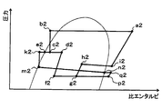
- the high-temperature and high-pressure refrigerant (point a2 in FIG. 12) discharged from the compressor 11 radiates heat with the radiator 12 and the intermediate-pressure refrigerant with the temperature type expansion valve 13 as in the first embodiment.
- the pressure is reduced until (a2 point ⁇ b2 point ⁇ c2 point in FIG. 12).
- the valve opening degree of the temperature type expansion valve 13 is adjusted so that the superheat degree of the refrigerant on the outlet side of the evaporator unit 30 (point i2 in FIG. 12) approaches the reference superheat degree.
- the refrigerant decompressed by the temperature type expansion valve 13 is separated into a gas-phase refrigerant and a liquid-phase refrigerant by the gas-liquid separation unit 14 (point c2 ⁇ d2 point, point c2 ⁇ e2 point in FIG. 12).
- the refrigerant in the gas-liquid two-phase state separated by the gas-liquid separation unit 14 flows into the nozzle portion 16a of the ejector 16 and is injected, as in the first embodiment.
- the refrigerant (q2 in FIG. 12) flowing out from the heat exchange passage 21 is sucked from the refrigerant suction port 16c of the ejector 16.
- the enthalpy of the refrigerant stored in the liquid storage unit 15 is lowered by exchanging heat with the refrigerant flowing through the heat exchange passage 21, and the refrigerant stored in the liquid storage unit 15 becomes a supercooled liquid phase refrigerant (FIG. 12 e2 points ⁇ k2 points).
- the enthalpy of the refrigerant flowing out from the suction side heat exchange unit 18b rises in the heat exchange passage 21 (point n2 ⁇ point q2 in FIG. 12).
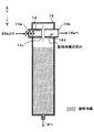
- FIG. 13 is a drawing corresponding to FIGS. 5 and 6 referred to in the description of the first embodiment.
- a gas return hole 13d is formed in the gas-liquid separation part 14 of the present embodiment on the cylindrical side surface downstream of the slit hole 14c.
- the gas return hole 13 d penetrates the inside and outside of the gas-liquid separation unit 14 and returns the gas-phase refrigerant in the liquid storage unit 15 to the internal space of the gas-liquid separation unit 14.
- the gas return hole 14d is formed so as to guide the gas-phase refrigerant in the liquid storage part 15 to the outlet part 14b side, that is, the inlet side of the nozzle part 16a, rather than the slit hole 14c of the gas-liquid separation part 14. .
- the gas return hole 14d is located between the slit hole 14c and the outlet part 14b in the axial direction of the gas-liquid separation part 14 having a cylindrical shape, and the gas-phase refrigerant in the liquid storage part 15 is used as a nozzle. It leads to the entrance side of the part 16a.
- the integrated evaporator unit 30 has been described, the evaporator unit 30 according to the present disclosure is not limited to this.
- the gas-liquid separation unit 14 the liquid storage unit 15, the ejector 16, the windward evaporator 17, and the leeward evaporator 18 are integrated.
- the temperature type expansion valve 13 may be integrated.
- the decompression device is not limited to the capillary tube. The decompression device may be an orifice or a nozzle.
- the total heat exchange part of the windward evaporator 17 may be an outflow side heat exchange part
- the total heat exchange part of the leeward evaporator 18 may be a suction side heat exchange part.
- Each component device constituting the ejector refrigeration cycle 10 is not limited to that disclosed in the above-described embodiment.
- the compressor 11 is an engine-driven variable displacement compressor in the above-described embodiment.
- the compressor 11 is a fixed displacement compressor that adjusts the refrigerant discharge capacity by changing the operating rate of the compressor by the on / off of the electromagnetic clutch. It may be.
- the compressor 11 may be an electric compressor that includes a fixed displacement compression mechanism and an electric motor and operates when supplied with electric power. In the electric compressor, the refrigerant discharge capacity can be controlled by adjusting the rotation speed of the electric motor.
- the radiator 12 is a subcool type heat exchanger in the above-described embodiment, but may be a normal radiator including only the condensing unit 12a. Furthermore, the radiator 12 is a combination of a normal radiator and a liquid receiver (receiver) that separates the refrigerant radiated by the radiator into a gas-phase refrigerant and a liquid-phase refrigerant and stores excess liquid-phase refrigerant. It may be a receiver integrated condenser.
- the heat exchange passage 21 is added as a configuration that functions in the same manner as the internal heat exchanger in the normal refrigeration cycle apparatus, but the heat exchange passage 21 is not an essential configuration. Therefore, the heat exchange passage 21 is abolished, and an internal heat exchanger for exchanging heat between the high-pressure refrigerant on the outlet side of the radiator 12 and the low-pressure refrigerant on the suction side of the compressor 11 is added to the outside of the evaporator unit 30. Also good.
- the refrigerant is R1234yf in the above-described embodiment, but other refrigerants such as R134a, R600a, R410A, R404A, R32, R407C, HFO-1234ze, and HFO-1234zd may be used.
- the refrigerant may be a mixed refrigerant obtained by mixing a plurality of refrigerants among R1234yf, R134a, R600a, R410A, R404A, R32, R407C, HFO-1234ze, and HFO-1234zd.
- the evaporator unit 30 is applied to the ejector refrigeration cycle 10 mounted on a vehicle.
- the evaporator unit 30 is not limited to an ejector refrigeration cycle for a vehicle, and may be applied to an ejector refrigeration cycle for stationary use.
- the gas-liquid separators 14 and 24 described in the second and third embodiments may be applied to the evaporator unit 30 that realizes the cycle configuration described in the fourth embodiment.
- the gas return hole 14d described in the fifth embodiment may be formed in the gas-liquid separation unit 14 described in the second embodiment.
Landscapes
- Engineering & Computer Science (AREA)
- Physics & Mathematics (AREA)
- Mechanical Engineering (AREA)
- Thermal Sciences (AREA)
- General Engineering & Computer Science (AREA)
- Chemical & Material Sciences (AREA)
- Analytical Chemistry (AREA)
- Power Engineering (AREA)
- Air-Conditioning For Vehicles (AREA)
Abstract
La présente invention concerne une unité à évaporateurs équipée d'un séparateur gaz-liquide (14, 24), d'un réservoir de liquide (15), d'un éjecteur (16), d'un dispositif de décompression (19) et d'évaporateurs (17, 18). Le séparateur gaz-liquide sépare un réfrigérant en un réfrigérant en phase gazeuse et un réfrigérant en phase liquide. Le réservoir de liquide retient le réfrigérant en phase liquide. L'éjecteur présente un corps (16b), qui est composé d'une buse (16a), d'un orifice d'aspiration de réfrigérant (16c), et d'un amplificateur (16d). La buse décompresse le réfrigérant contenant le réfrigérant en phase gazeuse. L'orifice d'aspiration de réfrigérant aspire le réfrigérant en tant que réfrigérant d'aspiration par l'action d'aspiration du réfrigérant à jet haute vitesse projeté à partir de la buse. L'amplificateur mélange le réfrigérant de jet et le réfrigérant d'aspiration, et augmente la pression. Le dispositif de décompression décompresse le réfrigérant en phase liquide s'écoulant du réservoir de liquide. Les évaporateurs présentent des échangeurs de chaleur côté évacuation (17a, 18a, 17b) et un échangeur de chaleur côté aspiration (18b). Les échangeurs de chaleur côté évacuation permettent d'évaporer le réfrigérant s'écoulant de l'amplificateur. L'échangeur de chaleur côté aspiration évapore le réfrigérant décompressé par le dispositif de décompression, et amène le réfrigérant à s'écouler dans l'orifice d'aspiration de réfrigérant.
Applications Claiming Priority (4)
| Application Number | Priority Date | Filing Date | Title |
|---|---|---|---|
| JP2016044317 | 2016-03-08 | ||
| JP2016-044317 | 2016-03-08 | ||
| JP2017-008284 | 2017-01-20 | ||
| JP2017008284A JP2017161214A (ja) | 2016-03-08 | 2017-01-20 | 蒸発器ユニット |
Publications (1)
| Publication Number | Publication Date |
|---|---|
| WO2017154603A1 true WO2017154603A1 (fr) | 2017-09-14 |
Family
ID=59789461
Family Applications (1)
| Application Number | Title | Priority Date | Filing Date |
|---|---|---|---|
| PCT/JP2017/006966 Ceased WO2017154603A1 (fr) | 2016-03-08 | 2017-02-24 | Unité à évaporateurs |
Country Status (1)
| Country | Link |
|---|---|
| WO (1) | WO2017154603A1 (fr) |
Citations (11)
| Publication number | Priority date | Publication date | Assignee | Title |
|---|---|---|---|---|
| JPS5926569U (ja) * | 1982-08-10 | 1984-02-18 | ダイキン工業株式会社 | 2冷媒方式冷凍装置 |
| JPS59145682U (ja) * | 1983-03-22 | 1984-09-28 | 鈴木 茂 | 冷凍機用アキユムレ−タ− |
| JPS62198467U (fr) * | 1986-06-04 | 1987-12-17 | ||
| JP2007040690A (ja) * | 2005-04-01 | 2007-02-15 | Denso Corp | エジェクタ式冷凍サイクル |
| JP2007046806A (ja) * | 2005-08-08 | 2007-02-22 | Denso Corp | エジェクタ式サイクル |
| JP2008304077A (ja) * | 2007-06-05 | 2008-12-18 | Denso Corp | エジェクタ式冷凍サイクル |
| JP2010038454A (ja) * | 2008-08-05 | 2010-02-18 | Denso Corp | 膨張弁及びそれを備えた蒸気圧縮式冷凍サイクル |
| JP2011220551A (ja) * | 2010-04-05 | 2011-11-04 | Denso Corp | 蒸発器ユニット |
| JP2013096581A (ja) * | 2011-10-27 | 2013-05-20 | Denso Corp | 冷媒用の遠心式分配器および冷凍サイクル |
| US20130251505A1 (en) * | 2010-11-30 | 2013-09-26 | Carrier Corporation | Ejector Cycle |
| JP2014055765A (ja) * | 2009-01-12 | 2014-03-27 | Denso Corp | 蒸発器ユニット |
-
2017
- 2017-02-24 WO PCT/JP2017/006966 patent/WO2017154603A1/fr not_active Ceased
Patent Citations (11)
| Publication number | Priority date | Publication date | Assignee | Title |
|---|---|---|---|---|
| JPS5926569U (ja) * | 1982-08-10 | 1984-02-18 | ダイキン工業株式会社 | 2冷媒方式冷凍装置 |
| JPS59145682U (ja) * | 1983-03-22 | 1984-09-28 | 鈴木 茂 | 冷凍機用アキユムレ−タ− |
| JPS62198467U (fr) * | 1986-06-04 | 1987-12-17 | ||
| JP2007040690A (ja) * | 2005-04-01 | 2007-02-15 | Denso Corp | エジェクタ式冷凍サイクル |
| JP2007046806A (ja) * | 2005-08-08 | 2007-02-22 | Denso Corp | エジェクタ式サイクル |
| JP2008304077A (ja) * | 2007-06-05 | 2008-12-18 | Denso Corp | エジェクタ式冷凍サイクル |
| JP2010038454A (ja) * | 2008-08-05 | 2010-02-18 | Denso Corp | 膨張弁及びそれを備えた蒸気圧縮式冷凍サイクル |
| JP2014055765A (ja) * | 2009-01-12 | 2014-03-27 | Denso Corp | 蒸発器ユニット |
| JP2011220551A (ja) * | 2010-04-05 | 2011-11-04 | Denso Corp | 蒸発器ユニット |
| US20130251505A1 (en) * | 2010-11-30 | 2013-09-26 | Carrier Corporation | Ejector Cycle |
| JP2013096581A (ja) * | 2011-10-27 | 2013-05-20 | Denso Corp | 冷媒用の遠心式分配器および冷凍サイクル |
Similar Documents
| Publication | Publication Date | Title |
|---|---|---|
| US7987685B2 (en) | Refrigerant cycle device with ejector | |
| JP5413393B2 (ja) | 冷媒分配器および冷凍サイクル | |
| CN104487786B (zh) | 制冷循环装置 | |
| US20160200175A1 (en) | Ejector refrigeration cycle | |
| US9784487B2 (en) | Decompression device having flow control valves and refrigeration cycle with said decompression device | |
| JP6277869B2 (ja) | エジェクタ式冷凍サイクル | |
| US20080098757A1 (en) | Refrigerant cycle device | |
| WO2013073185A1 (fr) | Dispositif à cycle de réfrigération du type à éjecteurs | |
| US11549522B2 (en) | Ejector | |
| US20150033791A1 (en) | Ejector | |
| US20160047586A1 (en) | Ejector | |
| WO2016021141A1 (fr) | Évaporateur | |
| JP2008304077A (ja) | エジェクタ式冷凍サイクル | |
| JP6555203B2 (ja) | 蒸発器ユニット | |
| JP6327088B2 (ja) | エジェクタ式冷凍サイクル | |
| JP2009300027A (ja) | エジェクタおよびエジェクタ式冷凍サイクル | |
| JP2017161214A (ja) | 蒸発器ユニット | |
| JP2019020063A (ja) | エジェクタ式冷凍サイクル | |
| JP2007040612A (ja) | 蒸気圧縮式サイクル | |
| JP6780567B2 (ja) | 気液分離器、および冷凍サイクル装置 | |
| WO2019208428A1 (fr) | Cycle de réfrigération de type-éjecteur | |
| JP6547698B2 (ja) | エジェクタ式冷凍サイクル | |
| WO2017154603A1 (fr) | Unité à évaporateurs | |
| JP4888050B2 (ja) | 冷凍サイクル装置 | |
| JP6717252B2 (ja) | 気液分離器、および冷凍サイクル装置 |
Legal Events
| Date | Code | Title | Description |
|---|---|---|---|
| NENP | Non-entry into the national phase |
Ref country code: DE |
|
| 121 | Ep: the epo has been informed by wipo that ep was designated in this application |
Ref document number: 17762943 Country of ref document: EP Kind code of ref document: A1 |
|
| 122 | Ep: pct application non-entry in european phase |
Ref document number: 17762943 Country of ref document: EP Kind code of ref document: A1 |