WO2017154611A1 - Dispositif de traitement d'informations, procédé de traitement d'informations, et programme - Google Patents
Dispositif de traitement d'informations, procédé de traitement d'informations, et programme Download PDFInfo
- Publication number
- WO2017154611A1 WO2017154611A1 PCT/JP2017/006993 JP2017006993W WO2017154611A1 WO 2017154611 A1 WO2017154611 A1 WO 2017154611A1 JP 2017006993 W JP2017006993 W JP 2017006993W WO 2017154611 A1 WO2017154611 A1 WO 2017154611A1
- Authority
- WO
- WIPO (PCT)
- Prior art keywords
- information
- projector
- projection area
- projection
- video
- Prior art date
- Legal status (The legal status is an assumption and is not a legal conclusion. Google has not performed a legal analysis and makes no representation as to the accuracy of the status listed.)
- Ceased
Links
Images




Classifications
-
- G—PHYSICS
- G03—PHOTOGRAPHY; CINEMATOGRAPHY; ANALOGOUS TECHNIQUES USING WAVES OTHER THAN OPTICAL WAVES; ELECTROGRAPHY; HOLOGRAPHY
- G03B—APPARATUS OR ARRANGEMENTS FOR TAKING PHOTOGRAPHS OR FOR PROJECTING OR VIEWING THEM; APPARATUS OR ARRANGEMENTS EMPLOYING ANALOGOUS TECHNIQUES USING WAVES OTHER THAN OPTICAL WAVES; ACCESSORIES THEREFOR
- G03B21/00—Projectors or projection-type viewers; Accessories therefor
- G03B21/14—Details
- G03B21/147—Optical correction of image distortions, e.g. keystone
-
- H—ELECTRICITY
- H04—ELECTRIC COMMUNICATION TECHNIQUE
- H04N—PICTORIAL COMMUNICATION, e.g. TELEVISION
- H04N9/00—Details of colour television systems
- H04N9/12—Picture reproducers
- H04N9/31—Projection devices for colour picture display, e.g. using electronic spatial light modulators [ESLM]
- H04N9/3191—Testing thereof
- H04N9/3194—Testing thereof including sensor feedback
-
- G—PHYSICS
- G03—PHOTOGRAPHY; CINEMATOGRAPHY; ANALOGOUS TECHNIQUES USING WAVES OTHER THAN OPTICAL WAVES; ELECTROGRAPHY; HOLOGRAPHY
- G03B—APPARATUS OR ARRANGEMENTS FOR TAKING PHOTOGRAPHS OR FOR PROJECTING OR VIEWING THEM; APPARATUS OR ARRANGEMENTS EMPLOYING ANALOGOUS TECHNIQUES USING WAVES OTHER THAN OPTICAL WAVES; ACCESSORIES THEREFOR
- G03B21/00—Projectors or projection-type viewers; Accessories therefor
-
- G—PHYSICS
- G03—PHOTOGRAPHY; CINEMATOGRAPHY; ANALOGOUS TECHNIQUES USING WAVES OTHER THAN OPTICAL WAVES; ELECTROGRAPHY; HOLOGRAPHY
- G03B—APPARATUS OR ARRANGEMENTS FOR TAKING PHOTOGRAPHS OR FOR PROJECTING OR VIEWING THEM; APPARATUS OR ARRANGEMENTS EMPLOYING ANALOGOUS TECHNIQUES USING WAVES OTHER THAN OPTICAL WAVES; ACCESSORIES THEREFOR
- G03B21/00—Projectors or projection-type viewers; Accessories therefor
- G03B21/14—Details
-
- G—PHYSICS
- G03—PHOTOGRAPHY; CINEMATOGRAPHY; ANALOGOUS TECHNIQUES USING WAVES OTHER THAN OPTICAL WAVES; ELECTROGRAPHY; HOLOGRAPHY
- G03B—APPARATUS OR ARRANGEMENTS FOR TAKING PHOTOGRAPHS OR FOR PROJECTING OR VIEWING THEM; APPARATUS OR ARRANGEMENTS EMPLOYING ANALOGOUS TECHNIQUES USING WAVES OTHER THAN OPTICAL WAVES; ACCESSORIES THEREFOR
- G03B21/00—Projectors or projection-type viewers; Accessories therefor
- G03B21/14—Details
- G03B21/142—Adjusting of projection optics
-
- G—PHYSICS
- G06—COMPUTING OR CALCULATING; COUNTING
- G06T—IMAGE DATA PROCESSING OR GENERATION, IN GENERAL
- G06T7/00—Image analysis
- G06T7/50—Depth or shape recovery
- G06T7/521—Depth or shape recovery from laser ranging, e.g. using interferometry; from the projection of structured light
-
- G—PHYSICS
- G09—EDUCATION; CRYPTOGRAPHY; DISPLAY; ADVERTISING; SEALS
- G09G—ARRANGEMENTS OR CIRCUITS FOR CONTROL OF INDICATING DEVICES USING STATIC MEANS TO PRESENT VARIABLE INFORMATION
- G09G5/00—Control arrangements or circuits for visual indicators common to cathode-ray tube indicators and other visual indicators
-
- G—PHYSICS
- G09—EDUCATION; CRYPTOGRAPHY; DISPLAY; ADVERTISING; SEALS
- G09G—ARRANGEMENTS OR CIRCUITS FOR CONTROL OF INDICATING DEVICES USING STATIC MEANS TO PRESENT VARIABLE INFORMATION
- G09G5/00—Control arrangements or circuits for visual indicators common to cathode-ray tube indicators and other visual indicators
- G09G5/36—Control arrangements or circuits for visual indicators common to cathode-ray tube indicators and other visual indicators characterised by the display of a graphic pattern, e.g. using an all-points-addressable [APA] memory
-
- G—PHYSICS
- G09—EDUCATION; CRYPTOGRAPHY; DISPLAY; ADVERTISING; SEALS
- G09G—ARRANGEMENTS OR CIRCUITS FOR CONTROL OF INDICATING DEVICES USING STATIC MEANS TO PRESENT VARIABLE INFORMATION
- G09G5/00—Control arrangements or circuits for visual indicators common to cathode-ray tube indicators and other visual indicators
- G09G5/36—Control arrangements or circuits for visual indicators common to cathode-ray tube indicators and other visual indicators characterised by the display of a graphic pattern, e.g. using an all-points-addressable [APA] memory
- G09G5/38—Control arrangements or circuits for visual indicators common to cathode-ray tube indicators and other visual indicators characterised by the display of a graphic pattern, e.g. using an all-points-addressable [APA] memory with means for controlling the display position
-
- H—ELECTRICITY
- H04—ELECTRIC COMMUNICATION TECHNIQUE
- H04N—PICTORIAL COMMUNICATION, e.g. TELEVISION
- H04N5/00—Details of television systems
- H04N5/74—Projection arrangements for image reproduction, e.g. using eidophor
-
- H—ELECTRICITY
- H04—ELECTRIC COMMUNICATION TECHNIQUE
- H04N—PICTORIAL COMMUNICATION, e.g. TELEVISION
- H04N9/00—Details of colour television systems
- H04N9/12—Picture reproducers
- H04N9/31—Projection devices for colour picture display, e.g. using electronic spatial light modulators [ESLM]
-
- H—ELECTRICITY
- H04—ELECTRIC COMMUNICATION TECHNIQUE
- H04N—PICTORIAL COMMUNICATION, e.g. TELEVISION
- H04N9/00—Details of colour television systems
- H04N9/12—Picture reproducers
- H04N9/31—Projection devices for colour picture display, e.g. using electronic spatial light modulators [ESLM]
- H04N9/3102—Projection devices for colour picture display, e.g. using electronic spatial light modulators [ESLM] using two-dimensional electronic spatial light modulators
- H04N9/3111—Projection devices for colour picture display, e.g. using electronic spatial light modulators [ESLM] using two-dimensional electronic spatial light modulators for displaying the colours sequentially, e.g. by using sequentially activated light sources
- H04N9/3114—Projection devices for colour picture display, e.g. using electronic spatial light modulators [ESLM] using two-dimensional electronic spatial light modulators for displaying the colours sequentially, e.g. by using sequentially activated light sources by using a sequential colour filter producing one colour at a time
-
- H—ELECTRICITY
- H04—ELECTRIC COMMUNICATION TECHNIQUE
- H04N—PICTORIAL COMMUNICATION, e.g. TELEVISION
- H04N9/00—Details of colour television systems
- H04N9/12—Picture reproducers
- H04N9/31—Projection devices for colour picture display, e.g. using electronic spatial light modulators [ESLM]
- H04N9/3102—Projection devices for colour picture display, e.g. using electronic spatial light modulators [ESLM] using two-dimensional electronic spatial light modulators
- H04N9/312—Driving therefor
-
- H—ELECTRICITY
- H04—ELECTRIC COMMUNICATION TECHNIQUE
- H04N—PICTORIAL COMMUNICATION, e.g. TELEVISION
- H04N9/00—Details of colour television systems
- H04N9/12—Picture reproducers
- H04N9/31—Projection devices for colour picture display, e.g. using electronic spatial light modulators [ESLM]
- H04N9/3141—Constructional details thereof
-
- G—PHYSICS
- G03—PHOTOGRAPHY; CINEMATOGRAPHY; ANALOGOUS TECHNIQUES USING WAVES OTHER THAN OPTICAL WAVES; ELECTROGRAPHY; HOLOGRAPHY
- G03B—APPARATUS OR ARRANGEMENTS FOR TAKING PHOTOGRAPHS OR FOR PROJECTING OR VIEWING THEM; APPARATUS OR ARRANGEMENTS EMPLOYING ANALOGOUS TECHNIQUES USING WAVES OTHER THAN OPTICAL WAVES; ACCESSORIES THEREFOR
- G03B21/00—Projectors or projection-type viewers; Accessories therefor
- G03B21/14—Details
- G03B21/145—Housing details, e.g. position adjustments thereof
-
- G—PHYSICS
- G09—EDUCATION; CRYPTOGRAPHY; DISPLAY; ADVERTISING; SEALS
- G09G—ARRANGEMENTS OR CIRCUITS FOR CONTROL OF INDICATING DEVICES USING STATIC MEANS TO PRESENT VARIABLE INFORMATION
- G09G2340/00—Aspects of display data processing
- G09G2340/04—Changes in size, position or resolution of an image
- G09G2340/0464—Positioning
Definitions
- the present technology relates to an information processing device, an information processing method, and a program, and more particularly, to an information processing device, an information processing method, and a program that stabilize the position of an image projected by a projector.
- the position of an image (internal content) to be projected in the display space may be determined in advance.
- the direction of the drive projector changes and the projection area moves, it is necessary to move the range of the projected image in accordance with the position of the projection area to be moved.
- the time difference between the movement of the projection region and the movement of the range of the projected image becomes large, the image is not localized at a predetermined position, and the image is shifted or shaken.
- the present technology makes it possible to stabilize the position of the image projected by the projector.
- An information processing apparatus includes an acquisition unit that acquires projection area information, which is information related to a projection area range of a projector, and a range of content displayed in the projection area based on the projection area information.
- a video control unit for controlling a display video range.
- the projector includes a first color image corresponding to one image constituting the video of the content, and a second color image corresponding to the one image and different from the first color. Projecting at different times, the video control unit can control the position of the first color image or the second color image based on the projection area information.
- the video control unit controls the position of the first color image and the second color image as viewed from the projector as the moving speed of the projection area of the projector increases. Can be made.
- the projector includes a first color image corresponding to one image constituting the video of the content, and a second color image corresponding to the one image and different from the first color. Projecting at different times, the video control unit determines the projection direction of the projector until the projection of the first color image and the second color image corresponding to the one image is completed. The movement of the projector in the projection direction by the driving unit to be controlled can be stopped.
- the video control unit stops the movement of the projector in the projection direction by the driving unit before starting the projection of the one image, and the first color image corresponding to the one image and the first image After the projection of the two-color image is completed, the movement of the projection direction of the projector by the driving unit can be resumed.
- the projection area information can be calculated based on control information of a drive unit that controls the projection direction of the projector.
- the projection area information may include a predicted value related to the range of the projection area based on the control information and characteristics of the drive unit.
- a calculation unit that calculates the projection area information based on the control information of the drive unit can be further provided.
- the projector and the driving unit can be further provided.
- the projection area information can be calculated based on information from a sensor that detects the movement of the projector.
- the projection area information may include a predicted value related to the range of the projection area based on information from the sensor.
- a calculation unit that calculates the projection area information based on information from the sensor can be further provided.
- the projector and the sensor can be further provided.
- the projection area information can include at least one of information indicating the position of the projection area or information indicating the movement direction and the movement amount of the projection area.
- the position of the projection area or the movement direction and amount of the projection area is calculated based on the distance between the projector and the projection area based on the depth information of the projection target area to be projected. be able to.
- a map generation unit that generates a map including the depth information of the projection target area can be further provided.
- the video control unit can control the display video range based on video position information indicating a video display position set in advance for the projection target area.
- the video control unit can set the display video range based on the projection area information, and cause the projector to project a video corresponding to the set display video range.
- An information processing method includes an acquisition control step for controlling acquisition of projection area information that is information relating to a projection area range of a projector, and content displayed in the projection area based on the projection area information And a video control step for controlling a display video range that is a range of
- a program includes an acquisition control step for controlling acquisition of projection area information that is information related to a projection area range of a projector, and a range of content displayed in the projection area based on the projection area information. And causing the computer system to execute processing including a video control step for controlling the display video range.
- projection area information that is information relating to a range of the projection area of the projector is acquired, and a display video range that is a range of content displayed in the projection area is controlled based on the projection area information. Is done.
- the position of the image projected by the projector can be stabilized.
- FIG. 1 is a block diagram illustrating an embodiment of an AV system to which the present technology is applied. It is a schematic diagram which shows the structural example of the external appearance of the drive type projector of the AV system of FIG. It is a flowchart for demonstrating the space map production
- FIG. 2 is a flowchart for explaining display control processing for realizing a first method for color braking countermeasures executed by the AV system of FIG. 1. It is a figure for demonstrating the 1st method of a color braking countermeasure. It is a figure for demonstrating the 2nd method of a color braking countermeasure. It is a block diagram which shows one Embodiment of the handy type projector to which this technique is applied. It is a block diagram which shows the structural example of a computer.
- content is a concept that includes parts (characters, icons, etc.) as well as video (still images, moving images, etc.) and includes a state (data) prior to video.
- FIG. 1 is a block diagram illustrating a configuration example of functions of the AV system 10.
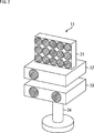
- FIG. 2 is a schematic diagram showing an example of the external configuration of the drive projector 11 that constitutes the AV system 10.
- the AV system 10 is a system that projects a video in a predetermined space (hereinafter referred to as a display space) and outputs a sound accompanying the video.
- the AV system 10 can freely change the display position of the video and the position of the virtual sound source in the display space, and is used for, for example, projection mapping.
- the AV system 10 includes a drive projector 11, a sensor unit 12, an operation unit 13, and an information processing device 14.
- the drive type projector 11 includes a reflection type speaker 31, a projector 32, a depth sensor 33, and a drive unit 34. As shown in FIG. 2, in the drive projector 11, the depth sensor 33 is installed on the drive unit 34, the projector 32 is installed on the depth sensor 33, and the reflective speaker 31 is installed on the projector 32. ing.
- the reflective speaker 31 is a speaker that generates a virtual sound source at a reflection position by applying an output sound to a desired position in the display space and reflecting it under the control of the information processing apparatus 14. The user feels that sound is being output from the position of the virtual sound source.
- the reflection type speaker 31 is not particularly limited as long as it is a speaker capable of generating a virtual sound source at a reflection position.
- the reflective speaker 31 is constituted by a super-directional speaker having a sharp directivity.
- an ultrasonic speaker (parametric speaker) that outputs a signal obtained by modulating a carrier wave composed of ultrasonic waves by a predetermined method.
- the case where the reflective speaker 31 outputs an output sound toward the virtual sound source and the output sound is reflected by the virtual sound source may be simply expressed as a sound output from the virtual sound source.
- the projector 32 projects an image based on the image data supplied from the information processing device 14 onto a wall or an object in the display space under the control of the information processing device 14. Note that the method of the projector 32 is not limited to a specific method, and any method can be adopted.
- the depth sensor 33 is a distance image indicating the distance from the drive projector 11 (more precisely, the depth sensor 33) at each position in the display space using, for example, infrared light under the control of the information processing device 14. And the captured distance image is supplied to the information processing device 14.
- a method of the depth sensor 33 any method such as a TOF (Time of Flight) method, a pattern irradiation method, a stereo camera method, or the like can be adopted.
- the drive unit 34 controls the output direction of the reflective speaker 31, the projection direction of the projector 32, and the shooting direction of the depth sensor 33 under the control of the information processing device 14.
- the drive unit 34 includes a pan motor 41, a tilt motor 42, and a motor control unit 43.
- the pan motor 41 is a motor that rotates the reflective speaker 31, the projector 32, and the depth sensor 33 in the pan direction (horizontal direction).
- the pan motor 41 includes an encoder, and supplies the motor control unit 43 with detection results of the rotational speed and rotational position of the pan motor 41, for example.
- the tilt motor 42 is a motor that rotates the reflective speaker 31, the projector 32, and the depth sensor 33 in the tilt direction (vertical direction).
- the tilt motor 42 includes an encoder, and supplies the motor control unit 43 with detection results of the rotational speed and rotational position of the tilt motor 42, for example.
- the motor control unit 43 controls the rotation of the pan motor 41 and the tilt motor 42 under the control of the information processing apparatus 14. Further, the motor control unit 43 supplies control information of the drive unit 34 to the information processing apparatus 14.
- the control information of the drive unit 34 includes, for example, the rotation speed and rotation position of the pan motor 41 and the tilt motor 42.
- the drive unit 34 may be configured to be rotatable in the yaw direction (around the main axis in the image projection direction), for example.
- the drive unit 34 may further include a moving mechanism such as a motor or a wheel.
- the sensor unit 12 includes a camera 61, a fisheye camera 62, and a microphone 63.
- the camera 61 captures an image of the display space and supplies an image obtained as a result of the capturing (hereinafter referred to as a display space image) to the information processing apparatus 14.
- the display space image is used, for example, for detection of the position, line-of-sight direction, gesture, etc. of the user in the display space.
- the fisheye camera 62 is composed of a camera equipped with a fisheye lens, and takes a super wide-angle image.
- the fisheye camera 62 supplies an image obtained as a result of photographing (hereinafter referred to as a fisheye image) to the information processing apparatus 14.
- the fisheye image is used, for example, for detecting the irradiation position (pointing position) of infrared light emitted from the pointing device 81.
- the microphone 63 is used, for example, for detection of reflected sound with respect to output sound from the reflective speaker 31.
- the microphone 63 supplies an audio signal indicating the detected sound to the information processing apparatus 14.
- the operation unit 13 includes a pointing device 81.
- the pointing device 81 is an operation device for the user to point to a desired position.
- the pointing device 81 irradiates infrared light and points to a position (pointing position) according to the user's operation with the infrared light.
- the pointing device 81 may be configured by a dedicated device, or may be configured by a general-purpose device that can be used for other purposes such as a smartphone or a remote controller.
- the information processing apparatus 14 is configured by, for example, a computer or a processor such as a CPU and a memory.
- the information processing apparatus 14 is mainly used for controlling the drive projector 11.
- the information processing apparatus 14 includes an interface (I / F) unit 101, a pointing position detection unit 102, a user detection unit 103, a map generation unit 104, a storage unit 105, a movement amount calculation unit 106, an input unit 107, and a control unit 108. Is provided.
- the I / F unit 101 includes, for example, a communication device, a connector, and the like.
- the I / F unit 101 exchanges data and the like with the reflective speaker 31, the projector 32, the depth sensor 33, the motor control unit 43, the camera 61, the fisheye camera 62, and the microphone 63. Further, the I / F unit 101 supplies received data or the like to each unit of the information processing device 14 or acquires data to be transmitted or the like from each unit of the information processing device 14.
- any wired or wireless method can be adopted as the communication method of the I / F unit 101.
- the communication method of the I / F unit 101 may be changed for each communication target. Further, for example, the I / F unit 101 may perform direct communication with each communication target, or may perform communication via a network or the like.
- the pointing position detection unit 102 detects the pointing position by the pointing device 81 based on the fisheye image photographed by the fisheye camera 62.
- the pointing position detection unit 102 supplies the detection result to the control unit 108.
- any method can be adopted as a detection method of the pointing position detection unit 102.
- the user detection unit 103 detects, for example, the position, line-of-sight direction, gesture, and the like of the user in the display space based on the display space image captured by the camera 61.
- the user detection unit 103 supplies the detection result to the control unit 108.
- any method can be adopted as a detection method of the user detection unit 103.
- the map generation unit 104 controls the depth sensor 33 and the motor control unit 43 via the I / F unit 101, and controls the photographing of the distance image in the display space by the depth sensor 33. Then, the map generation unit 104 performs space recognition in the display space using the distance image, and generates a first space map indicating a three-dimensional shape such as an object or a wall in the display space.
- the first space map is made up of, for example, a three-dimensional point cloud map, and includes depth information indicating the distance from the drive projector 11 at each position in the display space.
- the map generation unit 104 controls the reflection type speaker 31 and the motor control unit 43 via the I / F unit 101 to control scanning in the display space of the output sound from the reflection type speaker 31. Then, the map generation unit 104 recognizes the space in the display space based on the detection result of the reflected sound detected by the microphone 63 when the output sound is scanned in the display space, and the object or wall in the display space. A second spatial map showing a three-dimensional shape such as is generated.
- the second space map is composed of, for example, a three-dimensional point cloud map, depth information indicating the distance from the drive projector 11 at each position in the display space, and reflection characteristics (for example, reflectance, reflection) at each position. Reflection characteristic information indicating a corner or the like).
- the map generation unit 104 generates an integrated space map obtained by integrating the first space map and the second space map.
- the integrated space map includes, for example, depth information indicating the distance from the driving projector 11 at each position in the display space, reflection characteristic information indicating the reflection characteristic at each position, and display of video at each position in the display space. It includes display characteristic information indicating whether or not video projection is possible.
- the integrated space map includes, for example, video position information indicating a video display position that is set in advance with respect to the display space.
- the map generation unit 104 stores the generated integrated space map in the storage unit 105.
- the map generation unit 104 detects the position of the microphone 63 or the like based on the first space map, for example.
- the map generation unit 104 supplies the detection result to the control unit 108.
- the position of the microphone 63 or the like may be detected based on a display space image photographed by the camera 61.
- the movement amount calculation unit 106 calculates or predicts the movement direction and movement amount of the projection area of the projector 32 based on the control information of the driving unit 34.
- the movement amount calculation unit 106 supplies the calculation result or prediction result of the movement direction and movement amount of the projection area to the control unit 108.
- the movement amount calculation unit 106 can also predict the movement direction and movement amount of the projection area based on the movement speed or acceleration of the projection area.
- the movement amount calculation unit 106 can also predict the movement direction and movement amount of the projection area based on the movement (angular) speed and (angular) acceleration in the projection direction of the projector 32.
- the input unit 107 includes, for example, an operation device, and is used to input commands and data (for example, video data and audio data) to the control unit 108.
- commands and data for example, video data and audio data
- the control unit 108 includes a video control unit 111 and an audio control unit 112.
- the video control unit 111 controls display of video by the drive projector 11.
- the video control unit 111 controls the projector 32 via the I / F unit 101 to control the content and display timing of the video to be displayed.
- the video control unit 111 controls the display video range based on, for example, a calculation result or a prediction result of the movement direction and movement amount of the projection area of the projector 32.
- the display video range is a range of content displayed in the projection area among the content set to be displayed in the display space.
- the video control unit 111 controls the motor control unit 43 via the I / F unit 101 to control the projection direction of the video of the projector 32 and the output direction of the reflective speaker 31.
- the display position of the image and the reflection position of the output sound (that is, the position of the virtual sound source) are controlled.
- the acoustic control unit 112 controls the output sound output from the reflective speaker 31.
- the acoustic control unit 112 controls the reflective speaker 31 via the I / F unit 101 to control the content, volume, output timing, and the like of the output sound.
- the description of the I / F unit 101 is omitted as appropriate for the sake of clarity.
- the video control unit 111 supplies video data to the projector 32 via the I / F unit 101, it is simply described that the video control unit 111 supplies video data to the projector 32.
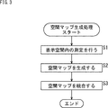
- this process is started, for example, when the drive projector 11 is installed or when the installation position of the drive projector 11 is moved.
- the movement of the installation position of the drive projector 11 can be detected based on, for example, a display space image captured by the camera 61 or can be detected by providing an acceleration sensor, a gyro sensor, or the like on the drive projector 11. it can.
- the space map generation process may be started when the state of the display space changes based on the display space image photographed by the camera 61.
- a change in the state of the display space for example, movement of a movable part in the display space (for example, opening / closing of a door, window, curtain, etc.), entry / exit of a person into / from the display space, and the like are assumed.
- step S1 the AV system 10 performs measurement in the display space.
- the map generation unit 104 controls the motor control unit 43 to rotate the driving unit 34 in the pan direction and the tilt direction, and causes the depth sensor 33 to scan all the areas in the display space, and also reflects the reflection type.
- the output sound (ultrasonic signal) output from the speaker 31 is scanned over all areas in the display space.
- the depth sensor 33 supplies the captured distance image to the map generation unit 104.
- reflected sound with respect to output sound from all areas in the display space is detected by the microphone 63.
- the microphone 63 supplies an audio signal indicating the detection result to the map generation unit 104.
- step S2 the map generation unit 104 generates a space map. Specifically, the map generation unit 104 generates a first spatial map based on the distance image captured by the depth sensor 33.
- the first space map includes depth information indicating the distance from the drive projector 11 at each position in the display space.
- the depth sensor 33 uses the reflection of infrared light, the depth information of a region where the reflection of infrared light such as a black wall, concrete, and glass cannot be used is missing in the first spatial map.
- the map generation unit 104 detects the position of the microphone 63 and the like in the display space based on the first space map. The map generation unit 104 supplies the detection result to the control unit 108.
- the map generation unit 104 generates a second spatial map based on the audio signal from the microphone 63. Specifically, the map generation unit 104 is based on the output direction of the output sound, the positions of the reflective speaker 31 and the microphone 63, and the time from when the output sound is output until when the reflected sound is received. The distance from the speaker 31 and the microphone 63 to each position in the display space is calculated.
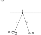
- the map generation unit 104 calculates the reflectance at each position in the display space based on the volume of the reflected sound. For example, as shown in FIG. 4, the case where the output sound output from the reflective speaker 31 is reflected at the reflection position P and the reflected sound is detected by the microphone 63 will be described.
- the distance between the reflective speaker 31 and the reflection position P is L1
- the distance between the reflection position P and the microphone 63 is L2.
- the attenuation in this case is referred to as a reference attenuation.
- the map generation unit 104 estimates the reflectance at the reflection position P based on the ratio of the attenuation amount of the reflected sound actually detected by the microphone 63 to the output sound and the reference attenuation amount.
- the map generation unit 104 generates a second space map including depth information indicating the distance from the driving projector 11 at each position in the display space and reflection characteristic information indicating the reflectance at each position in the display space. Generate.
- Depth information can be obtained even if the reflection of the output sound (ultrasound signal) can be used even if the reflection of infrared light is not available and the depth information is missing in the first spatial map. Depth information can be obtained.
- step S3 the map generation unit 104 integrates the spatial maps. Specifically, the map generation unit 104 supplements the depth information of the area where the depth information is missing in the first spatial map with the depth information of the second spatial map.
- the map generation unit 104 generates display characteristic information indicating whether or not video can be displayed at each position in the display space. For example, the map generation unit 104 determines that the position where the depth information is obtained in the first spatial map is a position where video can be displayed. On the other hand, the map generation unit 104 estimates the hardness and surface material of the position where the depth information is missing in the first spatial map based on the reflection characteristic information of the second spatial map. Based on the estimated hardness and surface material, the map generation unit 104 determines whether an image can be displayed at a position where depth information is missing in the first spatial map. Thereby, for example, a position where it is difficult to project an image such as a black wall, concrete, or glass is determined as a position where it is difficult to display the image.
- map generation unit 104 may determine that all positions where depth information is missing in the first spatial map are positions where video display is difficult.
- the map generation unit 104 uses the reflection characteristic information at each position in the display space of the second spatial map as it is as the reflection characteristic information of the integrated spatial map.
- the map generation unit 104 generates an integrated space map including depth information, display characteristic information, and reflection characteristic information at each position in the display space.
- the map generation unit 104 adds, for example, video position information indicating a video display position preset for the display space to the integrated space map.
- the video position information indicates, for example, the content of the video set to be displayed at each position in the display space.
- the video position information indicates the content of the video set to be displayed at each position in time series.
- the map generation unit 104 stores the generated integrated space map in the storage unit 105.
- information indicating that the space map is being generated may be output from the driven projector 11 by an image, sound, or the like.
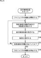
- Display control processing Next, display control processing executed by the AV system 10 will be described with reference to the flowchart of FIG. In this process, for example, the user gives the AV system 10 a command to move the projection area of the projector 32 by any method such as the pointing device 81, the input unit 107 of the information processing apparatus 14, the gesture, or the line of sight. When it starts.
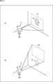
- a subject S1 that is a house is displayed in the projection area P1 in FIG.
- the display position of the subject S1 in the display space is fixed, and even if the projection area of the projector 32 moves from the area P1 to the area P3, the position of the subject S1 in the display space remains fixed.
- the subject S1 since the subject S1 is outside the projection region P3, the subject S1 is not displayed when the projection region moves to the region P3.
- the reflection type speaker 31 and the depth sensor 33 of the drive projector 11 are not shown for the sake of simplicity.
- step S51 the video control unit 111 starts driving the projector 32. Specifically, the video control unit 111 controls the motor control unit 43 to start rotation of at least one of the pan motor 41 and the tilt motor 42 according to the direction in which the projection area is moved.
- the movement amount calculation unit 106 calculates the movement direction and movement amount of the projection area.
- the movement amount calculation unit 106 acquires control information of the drive unit 34 from the motor control unit 43.
- the control information of the drive unit 34 includes the rotational speed and rotational position of the pan motor 41 and the tilt motor 42.
- the movement amount calculation unit 106 rotates and rotates the pan 32 and tilt directions of the projector 32 after projecting the image of the previous frame based on the rotation speed and rotation position of the pan motor 41 and the tilt motor 42. Detect corners.
- the movement amount calculation unit 106 detects the movement direction of the projection area based on the rotation directions of the pan direction and the tilt direction of the projector 32. Further, the movement amount calculation unit 106 obtains the distance between the projector 32 and the projection area based on the depth information of the integrated space map. The movement amount calculation unit 106 calculates the movement amount of the projection area in the pan direction and the tilt direction based on the rotation angles of the projector 32 in the pan direction and the tilt direction and the distance between the projector 32 and the projection area. To do. The movement amount calculation unit 106 supplies the calculation result of the movement direction and movement amount of the projection area to the control unit 108.
- the movement amount calculation unit 106 detects the rotation angle ⁇ of the projector 32 based on the rotation speed and rotation position of the tilt motor 42. Further, the movement amount calculation unit 106 obtains a distance L between the projector 32 and the projection region P1 based on the depth information of the integrated space map.
- the movement amount calculation unit 106 calculates the movement amount H between the projection area P1 and the projection area P2, for example, by the following equation (1).
- the movement amount H can be calculated by the following equation (1). is there.
- the movement amount H may be calculated by an expression different from Expression (1).
- the movement amount calculation unit 106 can calculate the movement amount H more quickly.
- the movement amount calculation unit 106 calculates the movement direction and movement amount of the projection area in consideration of the movement in the translation direction.
- the video control unit 111 sets a display video range.
- the video control unit 111 sets a display video range that is a video range to be displayed in the projection area after moving by the calculated movement direction and movement amount based on the video position information of the integrated space map.
- This display video range is a range that is moved from the display video range of the previous frame by the same amount as the movement amount of the projection region in the same direction as the calculated movement direction of the projection region.
- the video control unit 111 sets a display video range corresponding to the projection region P2.
- the display video range corresponding to the projection region P2 is a range that is moved upward by a distance H from the display video range corresponding to the projection region P1.
- step S54 the AV system 10 displays a video.
- the video control unit 111 supplies video data corresponding to the video in the display video range set in the process of step S53 to the projector 32.
- the projector 32 projects an image based on the image data supplied from the image control unit 111.
- the display video range moves upward by a distance H. Accordingly, the position of the subject S1 in the projection area P2 moves downward by a distance H from the position of the subject S1 in the projection area P1, contrary to the moving direction of the display video range.
- step S55 the video control unit 111 determines whether the movement of the projection area is completed. If the projection area has not reached the target position set as the movement destination, the video control unit 111 determines that the movement of the projection area has not been completed, and the process returns to step S52.
- steps S52 to S55 are repeatedly executed until it is determined in step S55 that the movement of the projection area is completed.
- step S55 when the projection area reaches the target position, the video control unit 111 determines that the movement of the projection area is completed, and the process proceeds to step S56.
- step S56 the video control unit 111 stops driving the projector 32. Specifically, the video control unit 111 controls the motor control unit 43 to stop the rotation of the pan motor 41 and the tilt motor 42.
- the display image range moves following the movement of the projection area, and the determined image is displayed at the determined location in the display space.
- the video control unit 111 starts driving the pan motor 41 and the tilt motor 42 via the motor control unit 43, it takes time until the pan motor 41 and the tilt motor 42 actually start rotating. Furthermore, it takes time for the rotational speed to stabilize and become constant after the pan motor 41 and the tilt motor 42 start rotating. Therefore, it takes time for the projection area of the projector 32 to start moving, and further, it takes time for the movement speed of the projection area to become stable and constant.
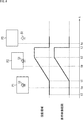
- FIG. 8 is a diagram showing the relationship between the projection area and the display video range when the projection area of the projector 32 is moved, as shown in FIGS. 6 and 7.
- a projection area and an image displayed in the projection area are schematically shown.
- a graph showing the movement speed of the projection area and the display video range is displayed below the figure.
- the horizontal axis of the graph indicates time, and the vertical axis indicates the moving speed.
- the tilt motor 42 starts rotating at time t1 and the movement of the projection area is started. Thereafter, the rotation speed of the tilt motor 42 is gradually accelerated, and the rotation speed becomes stable and constant at time t2. Then, at time t3, when the projection area reaches the area P3 that is the target position, the video control section 111 stops the rotation of the tilt motor 42 via the motor control section 43.
- the video control unit 111 moves the display video range in the same direction as the movement direction of the projection area by the same amount as the movement amount of the projection area between time ta and time tb.
- the subject S1 moves by the same amount as the movement amount of the projection area in the direction opposite to the movement direction of the projection area.
- the display position of the subject S1 does not move while being localized at a predetermined position in the display area.
- the video control unit 111 moves the display video range in the same direction as the movement direction of the projection area by the same amount as the movement amount of the projection area between time tb and time tc.
- the subject S1 moves in the opposite direction to the movement direction of the projection region by the same amount as the movement amount of the projection region, but the subject S1 goes out of the projection region P3 and is not displayed.
- the movement direction and the movement amount of the projection area in the pan direction and the tilt direction accompanying the rotation of the projector 32 in the pan direction and the tilt direction are quickly calculated, and the display image range moves quickly according to the movement of the projection area. To do.
- the operations of the pan motor 41 and the tilt motor 42 become unstable at the start of driving, the image is localized at a predetermined position, and the occurrence of image displacement and shaking is suppressed. That is, the position of the image projected by the projector 32 is stabilized.
- the video control unit 111 calculates the movement direction and movement amount of the projection area based on the control information of the driving unit 34, and sets the display video range based on the calculated movement direction and movement amount.
- An example of moving is shown. That is, an example is shown in which the display image range is moved following the movement of the projection area caused by the rotation of the projector 32 in the pan direction and the tilt direction.
- the characteristics of the drive unit 34 include response characteristics and rotation characteristics of the pan motor 41 and the tilt motor 42.
- the video control unit 111 predicts the moving direction and the moving amount of the projection area based on the control information and characteristics of the driving unit 34. Then, the video control unit 111 may set the display video range based on the predicted value of the movement direction and the movement amount of the projection area.
- the display image range can be moved almost simultaneously with the movement of the projection area, and the delay in the movement of the display image range with respect to the movement of the projection area becomes almost zero, thereby further suppressing the occurrence of image shift and shaking. can do. That is, the position of the image projected by the projector 32 can be further stabilized.
- the position of the image projected by the projector 32 can be further stabilized by detecting the actual projection direction of the projector 32, feeding back the detection result, and correcting the position of the projection area.
- the projector 32 is a single-plate DLP (Digital Light Processing) system projector, and R (red), G (green), and B (blue) for one image constituting the content video.
- DLP Digital Light Processing
- R red
- G green
- B blue
- images of each color are projected at different times in a time division manner.
- a user recognizes one color image by visually recognizing the image of each color projected at different time.
- one image is, for example, a still image, a single frame image of a moving image, or the like.
- color braking is a phenomenon in which, for example, color misregistration or the like occurs when images of different colors corresponding to the same image are projected at different positions.
- step S101 driving of the projector 32 is started in the same manner as in step S51 of FIG.
- step S102 the driving of the projector 32 is stopped as in the process of step S56 of FIG.
- step S103 the movement direction and movement amount of the projection area are calculated in the same manner as in step S52 of FIG.
- step S104 the display video range is set in the same manner as in step S53 of FIG.
- step S105 the AV system 10 displays a video.
- the video control unit 111 supplies video data corresponding to the video within the display video range set in the process of step S104 to the projector 32.
- the projector 32 projects an image based on the image data supplied from the image control unit 111.
- the projector 32 projects images of R, G, and B colors corresponding to images within the display image range onto the projection area at different times in a time division manner.
- the horizontal axis of the upper graph in FIG. 10 indicates time, and indicates the timing of projecting each color image of R, G, and B.
- step S102 the driving of the projector 32 is stopped, and the movement of the projection area is stopped. Therefore, for example, R, G, and B images for the subject S2 in FIG. 10 are projected at the same position in the display space. Thereby, the occurrence of color braking is suppressed, the display position of the subject S2 is stabilized, and the color of the subject is faithfully reproduced.
- step S106 it is determined whether or not the movement of the projection area is completed as in the process of step S55 in FIG. If it is determined that the movement of the projection area has not been completed, the process returns to step S101.
- steps S101 to S106 are repeatedly executed until it is determined in step S106 that the movement of the projection area is completed.
- step S106 if it is determined in step S106 that the movement of the projection area has been completed, the display control process ends.
- the driving of the projector 32 is temporarily stopped until the projection of all the color images corresponding to one image is completed, and the movement of the projection area is stopped. More specifically, when moving the projection area, the driving of the projector 32 is temporarily stopped before the projection of one image is started, and the movement of the projection area is temporarily stopped. Thereafter, after the projection of all color images corresponding to the one image is completed, the driving of the projector 32 is resumed, and the movement of the projection area is resumed. Thereby, as described above, the occurrence of color braking is suppressed, the projection position of the image is stabilized, and the color of the image is faithfully reproduced.
- the occurrence of color braking may be suppressed by controlling the position in the projection area of the R, G, and B color images projected from the projector 32.
- FIG. 11 shows the positional relationship between the displayable range A of the projector 32 and the R image Vr, the G image Vg, and the B image Vb.
- the displayable range A is a range in which the projector 32 can display an image, and is equal to the projection area of the projector 32.
- the projector 32 can display an image of an arbitrary size at an arbitrary position within the displayable range A. Therefore, when displaying a video having a size smaller than the displayable range A, the video control unit 111 can control the position of the video within the displayable range A by the video data supplied to the projector 32.
- the video control unit 111 can move the position of the video within the displayable range A (projection area) while fixing the projection direction of the projector 32.
- the position of the image is uniquely determined.
- the video control unit 111 controls the positions of the image Vr, the image Vg, and the image Vr within the displayable range A, so that the positions of the image Vr, the image Vg, and the image Vr that accompany the movement of the projection region. Prevent misalignment.
- the video control unit 111 indicates the position of the image Vb with respect to the image Vg in the coordinate system of the displayable range A in the displayable range A (projection region) from when the image Vg is projected to when the image Vb is projected.
- the amount of movement corresponding to the amount of movement of the displayable range A is moved in the direction to cancel the movement.
- the intervals between the images Vr, Vg, and Vb in the coordinate system of the displayable range A become longer, and the positions of the images Vr, Vg, and Vb viewed from the projector 32 are changed. Leave.
- the slower the movement speed of the projection area the shorter the intervals between the images Vr, Vg, and Vb in the coordinate system of the displayable range A, and the positions of the images Vr, Vg, and Vb viewed from the projector 32. Get closer.
- the positions of the images Vr, Vg, and Vb in the displayable range A are substantially the same.
- the projector 32 can control the position of each color image within the displayable range A instead of the video control unit 111.
- the position of the image of each color within the displayable range A by the position where the image control unit (not shown) of the projector 32 arranges the image of each color included in the image data supplied from the image control unit 111 in the frame buffer. Can be controlled.
- control vector for shifting the image of each color within the displayable range A is calculated by a predetermined function, for example, based on a vector based on the moving direction and moving amount of the projection area.
- the combination of the image colors to which the above-described color braking countermeasure can be applied is not limited to the above-described R, G, and B, and is arbitrary.
- the configuration example of the AV system 10 in FIG. 1 is an example, and can be changed as necessary.
- the reflective speaker 31 may be provided separately from the drive projector 11 so that it can be driven separately from the projector 32. Thereby, the position of the virtual sound source can be set more flexibly.
- a part or all of the information processing apparatus 14 can be provided in the drive type projector 11, or a part or all of the drive type projector 11 can be provided in the information processing apparatus 14.
- the movement amount calculation unit 106 may be provided in the drive projector 11 instead of the information processing apparatus 14.
- the I / F unit 101 of the information processing apparatus 14 acquires information regarding the movement direction and movement amount of the projection area from the drive projector 11 and supplies the information to the control unit 108. Then, the video control unit 111 of the control unit 108 controls the display video range based on the acquired information.
- a part or all of the sensor unit 12 may be provided in the drive projector 11 or the information processing apparatus 14.
- the present technology can also be applied to a case where the drive projector 11 does not control the drive unit 34 from the information processing device 14 and the projection projector 11 moves the projection region without being controlled by the information processing device 14. . That is, in this case as well, as in the method described above, the video control unit 111 calculates or predicts the movement direction and movement amount of the projection area based on the control information of the drive unit 34, and controls the display video range. Is possible.
- the configuration of the drive unit 34 is not limited to the example described above, and other configurations can be adopted. Even when other configurations are adopted, the movement direction and the movement amount of the projection area may be calculated or predicted based on the control information, characteristics, and the like of the drive unit 34 as in the above-described embodiment. .
- the projection area is moved by changing the orientation of the projector 32
- the image projected from the projector 32 is reflected by a reflector such as a mirror, and the orientation of the reflector
- the projection area may be moved by changing.
- the movement amount calculation unit 106 may calculate or predict the movement direction and movement amount of the projection region based on control information, characteristics, and the like of the driving unit that drives the reflector.
- the output sound output from the reflective speaker 31 is a reflector such as a mirror.
- the position of the virtual sound source may be moved by changing the direction of the reflector.
- the depth information in the display space may be acquired using a sensor other than the depth sensor 33.
- the present technology can also be applied to, for example, a handy type projector that moves the projection region by changing the direction that the user holds in his / her hand.
- FIG. 12 is a block diagram illustrating a configuration example of the handy projector 201.
- the handy type projector 201 includes a reflective speaker 211, a projector 212, a sensor unit 213, an input unit 214, and an information processing unit 215.
- the reflection type speaker 211 is a speaker that generates a virtual sound source at a reflection position by applying an output sound to a wall or the like and reflecting the same as the reflection type speaker 31 of FIG.
- the projector 212 projects an image based on the image data supplied from the information processing unit 215 onto a wall or an object in the display space, similarly to the projector 32 in FIG.
- the sensor unit 213 includes a depth sensor 221, a camera 222, a microphone 223, an acceleration sensor 224, and a gyro sensor 225.
- the depth sensor 221 captures a distance image indicating the distance from the depth sensor 221 using infrared light, and supplies the captured distance image to the information processing unit 215 in the same manner as the depth sensor 33 of FIG.
- the camera 222 images the periphery of the handy projector 201 and supplies an image obtained as a result of the imaging to the information processing unit 215.
- the image photographed by the camera 222 is used, for example, for detecting the position, line-of-sight direction, gesture, etc. of the user around the handy projector 201.
- the microphone 223 is used, for example, for detecting a reflected sound with respect to an output sound from the reflective speaker 211, similarly to the microphone 63 of FIG.
- the microphone 223 supplies an audio signal indicating the detected sound to the information processing unit 215.
- the acceleration sensor 224 detects, for example, accelerations in the three-axis directions of the X-axis, Y-axis, and Z-axis of the handy projector 201.
- the acceleration sensor 224 supplies a signal indicating the detection result to the information processing unit 215.
- the gyro sensor 225 detects, for example, angular velocities about three axes of the yaw axis, the pitch axis, and the roll axis of the handy projector 201.
- the gyro sensor 225 supplies a signal indicating the detection result to the information processing unit 215.
- the input unit 214 includes, for example, an operation device and is used to input commands and data (for example, video data and audio data) to the control unit 236 of the information processing unit 215.
- commands and data for example, video data and audio data
- the information processing unit 215 includes an interface (I / F) unit 231, a user detection unit 232, a map generation unit 233, a storage unit 234, a movement amount calculation unit 235, and a control unit 236.
- the I / F unit 231 includes, for example, a communication device, a connector, and the like, similar to the I / F unit 101 in FIG.
- the I / F unit 231 transmits and receives data and the like to and from the reflective speaker 211, the projector 212, the depth sensor 221, the camera 222, the microphone 223, the acceleration sensor 224, and the gyro sensor 225. Further, the I / F unit 231 supplies received data and the like to each unit of the information processing unit 215 and acquires data to be transmitted and the like from each unit of the information processing unit 215.
- the user detection unit 232 detects, for example, the position of the user around the handy projector 201, the line-of-sight direction, and the gesture based on the image taken by the camera 222.
- the user detection unit 232 supplies the detection result to the control unit 236.
- any method can be adopted as the detection method of the user detection unit 232.
- the map generation unit 233 uses the distance image captured by the depth sensor 221 and the detection result of the reflected sound with respect to the output sound of the reflective speaker 211 detected by the microphone 223. To generate an integrated spatial map.
- the map generation unit 233 stores the generated integrated space map in the storage unit 234.
- the movement amount calculation unit 235 detects the attitude and movement of the handy projector 201 based on information from sensors (for example, the acceleration sensor 224 and the gyro sensor 225) that detect the movement of the handy projector 201. Further, the movement amount calculation unit 235 calculates the movement direction and movement amount of the projection area of the projector 212 based on the detection result of the attitude and movement of the handy projector 201. The movement amount calculation unit 235 supplies the calculation result of the movement direction and movement amount of the projection area to the control unit 236.
- the movement amount calculation unit 235 predicts the attitude and movement of the handy projector 201 based on information from a sensor that detects the movement of the handy projector 201. Further, the movement amount calculation unit 235 predicts the movement direction and movement amount of the projection area of the projector 212 based on the prediction result of the attitude and movement of the handy projector 201. The movement amount calculation unit 235 supplies the prediction result of the movement direction and movement amount of the projection area to the control unit 236. Note that, for example, a technique disclosed in Japanese Patent Application Laid-Open No. 2015-72534 can be used for predicting the movement direction and the movement amount of the projection area.
- the movement amount calculation unit 235 can quickly calculate or predict the movement amount of the projection region by using the integrated space map. .
- the control unit 236 includes a video control unit 241 and an audio control unit 242.
- the video control unit 241 controls display of video by the projector 212.
- the video control unit 241 controls the projector 212 via the I / F unit 231 to control the content of the video to be displayed, the display timing, and the like.
- the video control unit 241 controls the display video range based on the calculation result or the prediction result of the movement direction and the movement amount of the projection area, similarly to the video control unit 111 of the information processing apparatus 14 in FIG.
- the display video range moves in accordance with the movement of the handy projector 201, the video is localized at a predetermined position, and the occurrence of video shifts, shaking, etc. is suppressed. . That is, the position of the image projected by the projector 212 is stabilized.
- the acoustic control unit 242 controls the output sound output from the reflective speaker 211.
- the acoustic control unit 242 controls the reflective speaker 211 via the I / F unit 231 to control the content, volume, and output timing of the output sound.
- a sensor other than the acceleration sensor 224 and the gyro sensor 225 or a combination of sensors may be used as a sensor for detecting the movement of the handy projector 201 (projector 212).
- the information included in the space map is not limited to the example described above, and can be changed as necessary. For example, based on information acquired by the camera 61 or the like, color information or texture information at each position in the display space may be included in the space map.
- the space map does not necessarily include information on all areas in the display space, and it is sufficient that the space map includes information on at least a projection target area to be projected.
- a part or all of the information of the space map may be given to the information processing device 14 or the information processing unit 215 from the outside.
- the example in which the movement direction and the movement amount of the projection area are used for the control of the display image range information on the range of the projection area in the display space when the projector next projects an image (projection). It is also possible to use information other than the movement direction and movement amount of the projection area. For example, instead of using the movement direction and amount of the projection area, the position of the projection area may be directly calculated or predicted and used for controlling the display video range.
- the type of video to which the present technology is applied is not particularly limited, and for example, moving images, still images, 2D videos, 3D videos, and the like are targeted.
- the video displayed in the display space changes with the passage of time. Therefore, for example, when setting the display video range corresponding to the projection area, the display video range is set for the video set to be displayed in the display space at the time when the video in the display video range is projected. You just have to do it.
- the second method for preventing color braking described above is that a display device other than a projector (for example, a liquid crystal display, an organic EL display, etc.) displays images of different colors for one image at different times in a time division manner.
- a display device other than a projector for example, a liquid crystal display, an organic EL display, etc.
- the present invention can also be applied when the user recognizes one color image.
- the display device including the display screen moves relative to the user who views the display screen
- the second method for color braking can be applied. Specifically, for example, when the display device moves with respect to the user, the display position of each color image in the display screen is shifted by the above-described method based on the moving direction and moving amount of the display device. The occurrence of color braking can be suppressed.
- the series of processes of the information processing apparatus 14 and the information processing unit 215 described above can be executed by hardware or can be executed by software.
- a program constituting the software is installed in the computer.
- the computer includes, for example, a general-purpose personal computer capable of executing various functions by installing various programs by installing a computer incorporated in dedicated hardware.
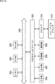
- FIG. 13 is a block diagram showing an example of the hardware configuration of a computer that executes the above-described series of processing by a program.
- a CPU Central Processing Unit
- ROM Read Only Memory
- RAM Random Access Memory
- An input / output interface 505 is further connected to the bus 504.
- An input unit 506, an output unit 507, a storage unit 508, a communication unit 509, and a drive 510 are connected to the input / output interface 505.
- the input unit 506 includes a keyboard, a mouse, a microphone, and the like.
- the output unit 507 includes a display, a speaker, and the like.
- the storage unit 508 includes a hard disk, a nonvolatile memory, and the like.
- the communication unit 509 includes a network interface or the like.
- the drive 510 drives a removable medium 511 such as a magnetic disk, an optical disk, a magneto-optical disk, or a semiconductor memory.
- the CPU 501 loads the program stored in the storage unit 508 to the RAM 503 via the input / output interface 505 and the bus 504 and executes the program, for example. Is performed.
- the program executed by the computer (CPU 501) can be provided by being recorded in, for example, a removable medium 511 as a package medium or the like.
- the program can be provided via a wired or wireless transmission medium such as a local area network, the Internet, or digital satellite broadcasting.
- the program can be installed in the storage unit 508 via the input / output interface 505 by attaching the removable medium 511 to the drive 510. Further, the program can be received by the communication unit 509 via a wired or wireless transmission medium and installed in the storage unit 508. In addition, the program can be installed in the ROM 502 or the storage unit 508 in advance.
- the program executed by the computer may be a program that is processed in time series in the order described in this specification, or in parallel or at a necessary timing such as when a call is made. It may be a program for processing.
- a plurality of computers may perform the above-described processing in cooperation.
- a computer system is configured by one or a plurality of computers that perform the above-described processing.
- the system means a set of a plurality of components (devices, modules (parts), etc.), and it does not matter whether all the components are in the same housing. Accordingly, a plurality of devices housed in separate housings and connected via a network and a single device housing a plurality of modules in one housing are all systems. .
- the present technology can take a cloud computing configuration in which one function is shared by a plurality of devices via a network and is jointly processed.
- each step described in the above flowchart can be executed by one device or can be shared by a plurality of devices.
- the plurality of processes included in the one step can be executed by being shared by a plurality of apparatuses in addition to being executed by one apparatus.
- the present technology can take the following configurations.
- An acquisition unit that acquires projection area information that is information relating to a range of the projection area of the projector;
- An information processing apparatus comprising: a video control unit that controls a display video range that is a range of content displayed in the projection region based on the projection region information.
- the projector differs between a first color image corresponding to one image constituting the video of the content and a second color image corresponding to the one image and different from the first color. Project into time, The information processing apparatus according to (1), wherein the video control unit controls the position of the first color image or the second color image based on the projection area information.
- the video control unit controls the position of the first color image and the second color image as viewed from the projector to be separated as the moving speed of the projection area of the projector increases.
- the information processing apparatus differs between a first color image corresponding to one image constituting the video of the content and a second color image corresponding to the one image and different from the first color.
- the video control unit includes a projector that controls a projection direction of the projector until the projection of the first color image and the second color image corresponding to the one image is completed.
- the information processing apparatus according to (1), wherein the movement in the projection direction is stopped.
- the video control unit stops the movement of the projector in the projection direction by the driving unit before starting the projection of the one image, and the first color image corresponding to the one image and the first image
- the projection area information is calculated based on control information of a driving unit that controls a projection direction of the projector.
- the projection area information includes a predicted value related to a range of the projection area based on control information and characteristics of the driving unit.
- the information processing apparatus according to (6) or (7), further including a calculation unit that calculates the projection area information based on control information of the drive unit.
- the information processing apparatus according to any one of (1) to (5), wherein the projection area information is calculated based on information from a sensor that detects a motion of the projector.
- the information processing apparatus according to (10), wherein the projection area information includes a predicted value related to a range of the projection area based on information from the sensor.
- the information processing apparatus according to (10) or (11), further including a calculation unit configured to calculate the projection area information based on information from the sensor.
- the position of the projection area, or the movement direction and the movement amount of the projection area are calculated based on the distance between the projector and the projection area based on the depth information of the projection target area to be projected.
- An acquisition control step for controlling the acquisition of projection area information which is information relating to the range of the projection area of the projector;
- a program for causing a computer system to execute processing including a video control step of controlling a display video range that is a range of content displayed in the projection region based on the projection region information.
Landscapes
- Engineering & Computer Science (AREA)
- Physics & Mathematics (AREA)
- General Physics & Mathematics (AREA)
- Signal Processing (AREA)
- Multimedia (AREA)
- Theoretical Computer Science (AREA)
- Computer Hardware Design (AREA)
- Optics & Photonics (AREA)
- Computer Vision & Pattern Recognition (AREA)
- Controls And Circuits For Display Device (AREA)
- Projection Apparatus (AREA)
- Transforming Electric Information Into Light Information (AREA)
- Video Image Reproduction Devices For Color Tv Systems (AREA)
Abstract
Priority Applications (4)
| Application Number | Priority Date | Filing Date | Title |
|---|---|---|---|
| EP17762951.6A EP3429193A4 (fr) | 2016-03-10 | 2017-02-24 | Dispositif de traitement d'informations, procédé de traitement d'informations, et programme |
| US16/070,692 US10620514B2 (en) | 2016-03-10 | 2017-02-24 | Information processing apparatus, information processing method, and program |
| JP2018504368A JP7052719B2 (ja) | 2016-03-10 | 2017-02-24 | 情報処理装置、情報処理方法、及び、プログラム |
| CN201780015032.0A CN108781266B (zh) | 2016-03-10 | 2017-02-24 | 信息处理装置、信息处理方法以及计算机可读存储介质 |
Applications Claiming Priority (2)
| Application Number | Priority Date | Filing Date | Title |
|---|---|---|---|
| JP2016-047658 | 2016-03-10 | ||
| JP2016047658 | 2016-03-10 |
Publications (1)
| Publication Number | Publication Date |
|---|---|
| WO2017154611A1 true WO2017154611A1 (fr) | 2017-09-14 |
Family
ID=59789446
Family Applications (1)
| Application Number | Title | Priority Date | Filing Date |
|---|---|---|---|
| PCT/JP2017/006993 Ceased WO2017154611A1 (fr) | 2016-03-10 | 2017-02-24 | Dispositif de traitement d'informations, procédé de traitement d'informations, et programme |
Country Status (5)
| Country | Link |
|---|---|
| US (1) | US10620514B2 (fr) |
| EP (1) | EP3429193A4 (fr) |
| JP (1) | JP7052719B2 (fr) |
| CN (1) | CN108781266B (fr) |
| WO (1) | WO2017154611A1 (fr) |
Families Citing this family (6)
| Publication number | Priority date | Publication date | Assignee | Title |
|---|---|---|---|---|
| KR102716952B1 (ko) * | 2017-03-28 | 2024-10-14 | 매직 립, 인코포레이티드 | 공간화된 오디오가 사용자 조작 가상 객체들에 결속된 증강 현실 시스템 |
| JP6785385B2 (ja) | 2018-03-07 | 2020-11-18 | マジック リープ, インコーポレイテッドMagic Leap,Inc. | 周辺デバイスの視覚的追跡 |
| JP2021089315A (ja) * | 2019-12-02 | 2021-06-10 | ソニーグループ株式会社 | 情報処理装置、および情報処理方法 |
| WO2021193213A1 (fr) * | 2020-03-26 | 2021-09-30 | ソニーグループ株式会社 | Dispositif de traitement d'informations, procédé de génération de modèle 3d et programme |
| JP7703907B2 (ja) * | 2021-06-02 | 2025-07-08 | セイコーエプソン株式会社 | プロジェクターおよびプロジェクターの制御方法 |
| CN113747133B (zh) * | 2021-09-01 | 2024-04-26 | 广景视睿科技(深圳)有限公司 | 一种投影方法、装置、投影设备及存储介质 |
Citations (7)
| Publication number | Priority date | Publication date | Assignee | Title |
|---|---|---|---|---|
| JP2005043570A (ja) * | 2003-07-25 | 2005-02-17 | Seiko Epson Corp | プロジェクタ |
| WO2008004438A1 (fr) * | 2006-07-03 | 2008-01-10 | Panasonic Corporation | Système de projecteur et procédé de projection d'image video |
| JP2011175051A (ja) * | 2010-02-24 | 2011-09-08 | Nikon Corp | プロジェクタ |
| JP2011248548A (ja) * | 2010-05-25 | 2011-12-08 | Fujitsu Ltd | コンテンツ決定プログラムおよびコンテンツ決定装置 |
| JP2013020199A (ja) * | 2011-07-14 | 2013-01-31 | Seiko Epson Corp | プロジェクションシステム、画像供給装置、プロジェクター、及び、画像投射方法 |
| JP2013109184A (ja) * | 2011-11-22 | 2013-06-06 | Canon Inc | 投射型表示装置 |
| JP2015119419A (ja) * | 2013-12-19 | 2015-06-25 | カシオ計算機株式会社 | 投影装置、投影方法及び投影プログラム |
Family Cites Families (12)
| Publication number | Priority date | Publication date | Assignee | Title |
|---|---|---|---|---|
| JP4232042B2 (ja) * | 2005-01-07 | 2009-03-04 | セイコーエプソン株式会社 | 投写制御システム、プロジェクタ、プログラム、情報記憶媒体および投写制御方法 |
| JP4126564B2 (ja) * | 2005-02-14 | 2008-07-30 | セイコーエプソン株式会社 | 画像処理システム、プロジェクタ、プログラム、情報記憶媒体および画像処理方法 |
| JP5308765B2 (ja) | 2008-10-03 | 2013-10-09 | パナソニック株式会社 | 照明装置 |
| JP5495572B2 (ja) * | 2009-01-07 | 2014-05-21 | キヤノン株式会社 | プロジェクタ・システム及びこれを含むビデオ会議システム |
| US9010942B2 (en) * | 2010-05-27 | 2015-04-21 | Kyocera Corporation | Mobile electronic device and image projection unit |
| US9300899B2 (en) * | 2013-03-13 | 2016-03-29 | Trimble Navigation Limited | Method for projecting an image |
| JP2014178393A (ja) * | 2013-03-14 | 2014-09-25 | Ricoh Co Ltd | 画像投影システム及び画像投影方法 |
| US9609262B2 (en) * | 2013-06-27 | 2017-03-28 | Intel Corporation | Device for adaptive projection |
| US9691357B2 (en) * | 2013-08-09 | 2017-06-27 | Lenovo (Beijing) Co., Ltd. | Information processing method and electronic device thereof, image calibration method and apparatus, and electronic device thereof |
| JP2015130555A (ja) * | 2014-01-06 | 2015-07-16 | 株式会社東芝 | 画像処理装置、画像処理方法、および画像投影装置 |
| JP6365079B2 (ja) * | 2014-08-01 | 2018-08-01 | セイコーエプソン株式会社 | プロジェクターおよびプロジェクターの調整方法 |
| US10066933B2 (en) * | 2015-05-04 | 2018-09-04 | Facebook, Inc. | Camera depth mapping using structured light patterns |
-
2017
- 2017-02-24 CN CN201780015032.0A patent/CN108781266B/zh active Active
- 2017-02-24 JP JP2018504368A patent/JP7052719B2/ja not_active Expired - Fee Related
- 2017-02-24 WO PCT/JP2017/006993 patent/WO2017154611A1/fr not_active Ceased
- 2017-02-24 US US16/070,692 patent/US10620514B2/en active Active
- 2017-02-24 EP EP17762951.6A patent/EP3429193A4/fr not_active Ceased
Patent Citations (7)
| Publication number | Priority date | Publication date | Assignee | Title |
|---|---|---|---|---|
| JP2005043570A (ja) * | 2003-07-25 | 2005-02-17 | Seiko Epson Corp | プロジェクタ |
| WO2008004438A1 (fr) * | 2006-07-03 | 2008-01-10 | Panasonic Corporation | Système de projecteur et procédé de projection d'image video |
| JP2011175051A (ja) * | 2010-02-24 | 2011-09-08 | Nikon Corp | プロジェクタ |
| JP2011248548A (ja) * | 2010-05-25 | 2011-12-08 | Fujitsu Ltd | コンテンツ決定プログラムおよびコンテンツ決定装置 |
| JP2013020199A (ja) * | 2011-07-14 | 2013-01-31 | Seiko Epson Corp | プロジェクションシステム、画像供給装置、プロジェクター、及び、画像投射方法 |
| JP2013109184A (ja) * | 2011-11-22 | 2013-06-06 | Canon Inc | 投射型表示装置 |
| JP2015119419A (ja) * | 2013-12-19 | 2015-06-25 | カシオ計算機株式会社 | 投影装置、投影方法及び投影プログラム |
Non-Patent Citations (1)
| Title |
|---|
| See also references of EP3429193A4 * |
Also Published As
| Publication number | Publication date |
|---|---|
| JP7052719B2 (ja) | 2022-04-12 |
| EP3429193A4 (fr) | 2019-04-17 |
| CN108781266A (zh) | 2018-11-09 |
| JPWO2017154611A1 (ja) | 2019-01-10 |
| CN108781266B (zh) | 2021-03-16 |
| US10620514B2 (en) | 2020-04-14 |
| US20190025681A1 (en) | 2019-01-24 |
| EP3429193A1 (fr) | 2019-01-16 |
Similar Documents
| Publication | Publication Date | Title |
|---|---|---|
| JP7052719B2 (ja) | 情報処理装置、情報処理方法、及び、プログラム | |
| US20240290359A1 (en) | Cinematic space-time view synthesis for enhanced viewing experiences in computing environments | |
| JP6860488B2 (ja) | 複合現実システム | |
| US8909375B2 (en) | Nodding mechanism for a single-scan sensor | |
| US20210302753A1 (en) | Control apparatus, control method, and program | |
| JP6249248B2 (ja) | 投影装置 | |
| US20170374331A1 (en) | Auto keystone correction and auto focus adjustment | |
| WO2017154610A1 (fr) | Dispositif de traitement d'informations, procédé de traitement d'informations, et programme | |
| JP2018523142A (ja) | 取込まれた像のパススルー表示 | |
| US11375244B2 (en) | Dynamic video encoding and view adaptation in wireless computing environments | |
| US20220239887A1 (en) | Shared viewing of video among multiple users | |
| US20160286186A1 (en) | Projection apparatus | |
| JP6307706B2 (ja) | 投影装置 | |
| US11269250B2 (en) | Information processing apparatus, information processing method, and program | |
| JP6167308B2 (ja) | 投影装置 | |
| CN119299636A (zh) | 全景投影方法、投影设备及存储介质 | |
| EP4384848B1 (fr) | Système de capture d'image comprenant un dispositif lidar et des caméras comportant un capteur d'obturateur roulant | |
| CN115103169A (zh) | 投影画面校正方法、装置、存储介质以及投影设备 | |
| JP2011239178A (ja) | 撮像装置 | |
| JP6641525B2 (ja) | 光学機器制御装置、光学機器制御方法、及び光学機器制御プログラム | |
| WO2018152061A1 (fr) | Utilisation de micro-miroirs pour améliorer le champ de vision d'une carte de profondeur 3d | |
| CN118838488A (zh) | 虚拟现实场景的交互方法、装置、电子设备和介质、产品 |
Legal Events
| Date | Code | Title | Description |
|---|---|---|---|
| WWE | Wipo information: entry into national phase |
Ref document number: 2018504368 Country of ref document: JP |
|
| NENP | Non-entry into the national phase |
Ref country code: DE |
|
| WWE | Wipo information: entry into national phase |
Ref document number: 2017762951 Country of ref document: EP |
|
| ENP | Entry into the national phase |
Ref document number: 2017762951 Country of ref document: EP Effective date: 20181010 |
|
| 121 | Ep: the epo has been informed by wipo that ep was designated in this application |
Ref document number: 17762951 Country of ref document: EP Kind code of ref document: A1 |