WO2017154640A1 - Dispositif, procédé et programme d'affichage d'image - Google Patents
Dispositif, procédé et programme d'affichage d'image Download PDFInfo
- Publication number
- WO2017154640A1 WO2017154640A1 PCT/JP2017/007502 JP2017007502W WO2017154640A1 WO 2017154640 A1 WO2017154640 A1 WO 2017154640A1 JP 2017007502 W JP2017007502 W JP 2017007502W WO 2017154640 A1 WO2017154640 A1 WO 2017154640A1
- Authority
- WO
- WIPO (PCT)
- Prior art keywords
- common
- image
- images
- medical images
- area
- Prior art date
- Legal status (The legal status is an assumption and is not a legal conclusion. Google has not performed a legal analysis and makes no representation as to the accuracy of the status listed.)
- Ceased
Links
Images





Classifications
-
- G—PHYSICS
- G06—COMPUTING OR CALCULATING; COUNTING
- G06T—IMAGE DATA PROCESSING OR GENERATION, IN GENERAL
- G06T3/00—Geometric image transformations in the plane of the image
- G06T3/40—Scaling of whole images or parts thereof, e.g. expanding or contracting
-
- A—HUMAN NECESSITIES
- A61—MEDICAL OR VETERINARY SCIENCE; HYGIENE
- A61B—DIAGNOSIS; SURGERY; IDENTIFICATION
- A61B6/00—Apparatus or devices for radiation diagnosis; Apparatus or devices for radiation diagnosis combined with radiation therapy equipment
- A61B6/46—Arrangements for interfacing with the operator or the patient
- A61B6/461—Displaying means of special interest
- A61B6/463—Displaying means of special interest characterised by displaying multiple images or images and diagnostic data on one display
-
- G—PHYSICS
- G06—COMPUTING OR CALCULATING; COUNTING
- G06T—IMAGE DATA PROCESSING OR GENERATION, IN GENERAL
- G06T7/00—Image analysis
- G06T7/30—Determination of transform parameters for the alignment of images, i.e. image registration
- G06T7/33—Determination of transform parameters for the alignment of images, i.e. image registration using feature-based methods
-
- G—PHYSICS
- G06—COMPUTING OR CALCULATING; COUNTING
- G06T—IMAGE DATA PROCESSING OR GENERATION, IN GENERAL
- G06T7/00—Image analysis
- G06T7/50—Depth or shape recovery
- G06T7/55—Depth or shape recovery from multiple images
-
- G—PHYSICS
- G06—COMPUTING OR CALCULATING; COUNTING
- G06V—IMAGE OR VIDEO RECOGNITION OR UNDERSTANDING
- G06V10/00—Arrangements for image or video recognition or understanding
- G06V10/20—Image preprocessing
- G06V10/25—Determination of region of interest [ROI] or a volume of interest [VOI]
-
- G—PHYSICS
- G06—COMPUTING OR CALCULATING; COUNTING
- G06V—IMAGE OR VIDEO RECOGNITION OR UNDERSTANDING
- G06V10/00—Arrangements for image or video recognition or understanding
- G06V10/20—Image preprocessing
- G06V10/28—Quantising the image, e.g. histogram thresholding for discrimination between background and foreground patterns
-
- G—PHYSICS
- G06—COMPUTING OR CALCULATING; COUNTING
- G06V—IMAGE OR VIDEO RECOGNITION OR UNDERSTANDING
- G06V10/00—Arrangements for image or video recognition or understanding
- G06V10/40—Extraction of image or video features
-
- G—PHYSICS
- G06—COMPUTING OR CALCULATING; COUNTING
- G06V—IMAGE OR VIDEO RECOGNITION OR UNDERSTANDING
- G06V10/00—Arrangements for image or video recognition or understanding
- G06V10/70—Arrangements for image or video recognition or understanding using pattern recognition or machine learning
- G06V10/74—Image or video pattern matching; Proximity measures in feature spaces
- G06V10/75—Organisation of the matching processes, e.g. simultaneous or sequential comparisons of image or video features; Coarse-fine approaches, e.g. multi-scale approaches; using context analysis; Selection of dictionaries
- G06V10/757—Matching configurations of points or features
-
- A—HUMAN NECESSITIES
- A61—MEDICAL OR VETERINARY SCIENCE; HYGIENE
- A61B—DIAGNOSIS; SURGERY; IDENTIFICATION
- A61B6/00—Apparatus or devices for radiation diagnosis; Apparatus or devices for radiation diagnosis combined with radiation therapy equipment
- A61B6/50—Apparatus or devices for radiation diagnosis; Apparatus or devices for radiation diagnosis combined with radiation therapy equipment specially adapted for specific body parts; specially adapted for specific clinical applications
- A61B6/503—Apparatus or devices for radiation diagnosis; Apparatus or devices for radiation diagnosis combined with radiation therapy equipment specially adapted for specific body parts; specially adapted for specific clinical applications for diagnosis of the heart
-
- A—HUMAN NECESSITIES
- A61—MEDICAL OR VETERINARY SCIENCE; HYGIENE
- A61B—DIAGNOSIS; SURGERY; IDENTIFICATION
- A61B6/00—Apparatus or devices for radiation diagnosis; Apparatus or devices for radiation diagnosis combined with radiation therapy equipment
- A61B6/50—Apparatus or devices for radiation diagnosis; Apparatus or devices for radiation diagnosis combined with radiation therapy equipment specially adapted for specific body parts; specially adapted for specific clinical applications
- A61B6/505—Apparatus or devices for radiation diagnosis; Apparatus or devices for radiation diagnosis combined with radiation therapy equipment specially adapted for specific body parts; specially adapted for specific clinical applications for diagnosis of bone
-
- G—PHYSICS
- G06—COMPUTING OR CALCULATING; COUNTING
- G06T—IMAGE DATA PROCESSING OR GENERATION, IN GENERAL
- G06T2207/00—Indexing scheme for image analysis or image enhancement
- G06T2207/10—Image acquisition modality
- G06T2207/10072—Tomographic images
- G06T2207/10081—Computed x-ray tomography [CT]
-
- G—PHYSICS
- G06—COMPUTING OR CALCULATING; COUNTING
- G06T—IMAGE DATA PROCESSING OR GENERATION, IN GENERAL
- G06T2207/00—Indexing scheme for image analysis or image enhancement
- G06T2207/20—Special algorithmic details
- G06T2207/20112—Image segmentation details
- G06T2207/20164—Salient point detection; Corner detection
-
- G—PHYSICS
- G06—COMPUTING OR CALCULATING; COUNTING
- G06T—IMAGE DATA PROCESSING OR GENERATION, IN GENERAL
- G06T2207/00—Indexing scheme for image analysis or image enhancement
- G06T2207/30—Subject of image; Context of image processing
- G06T2207/30004—Biomedical image processing
- G06T2207/30008—Bone
- G06T2207/30012—Spine; Backbone
-
- G—PHYSICS
- G06—COMPUTING OR CALCULATING; COUNTING
- G06T—IMAGE DATA PROCESSING OR GENERATION, IN GENERAL
- G06T2207/00—Indexing scheme for image analysis or image enhancement
- G06T2207/30—Subject of image; Context of image processing
- G06T2207/30004—Biomedical image processing
- G06T2207/30048—Heart; Cardiac
-
- G—PHYSICS
- G06—COMPUTING OR CALCULATING; COUNTING
- G06T—IMAGE DATA PROCESSING OR GENERATION, IN GENERAL
- G06T2207/00—Indexing scheme for image analysis or image enhancement
- G06T2207/30—Subject of image; Context of image processing
- G06T2207/30004—Biomedical image processing
- G06T2207/30061—Lung
-
- G—PHYSICS
- G06—COMPUTING OR CALCULATING; COUNTING
- G06V—IMAGE OR VIDEO RECOGNITION OR UNDERSTANDING
- G06V10/00—Arrangements for image or video recognition or understanding
- G06V10/70—Arrangements for image or video recognition or understanding using pattern recognition or machine learning
- G06V10/74—Image or video pattern matching; Proximity measures in feature spaces
- G06V10/75—Organisation of the matching processes, e.g. simultaneous or sequential comparisons of image or video features; Coarse-fine approaches, e.g. multi-scale approaches; using context analysis; Selection of dictionaries
- G06V10/759—Region-based matching
-
- G—PHYSICS
- G06—COMPUTING OR CALCULATING; COUNTING
- G06V—IMAGE OR VIDEO RECOGNITION OR UNDERSTANDING
- G06V2201/00—Indexing scheme relating to image or video recognition or understanding
- G06V2201/03—Recognition of patterns in medical or anatomical images
Definitions
- the present invention relates to an image display apparatus, method, and program for displaying a plurality of images for comparison.
- X-ray CT Computed Tomography
- ultrasound US
- MRI Magnetic Resonance Imaging
- PET PET
- SPET Single-Photon Emission Tomography
- comparative interpretation has been conventionally performed in which a plurality of medical images are displayed on a display device such as a liquid crystal display, and interpretation is performed while comparing the images. For example, the current and past medical images of the subject are displayed and comparatively interpreted, thereby confirming the degree of progression of the lesion or detecting an abnormality at an early stage.
- a technique for displaying a medical image on a display device has been proposed to facilitate such comparative interpretation.
- Patent Document 1 sets an enlargement ratio at which the sizes of common imaging parts are equal for two medical images for comparative interpretation, and displays the two medical images enlarged and reduced by the set enlargement ratio.
- a technique has been proposed.
- the subject When acquiring the medical image for performing the above-described comparative interpretation, the subject is imaged so that the region to be subjected to the comparative interpretation is included.
- the cervical vertebra when comparative interpretation is performed using a CT image of an axial cross section with the cervical spine as the subject, the cervical vertebra is not always located at the center of the image, and the cervical vertebra may be included at a position shifted from the center of the image.
- the size of the cervical spine region included in the image may differ between images.
- the CT image may or may not include the subject's shoulder.
- the present invention has been made in view of the above circumstances, and an object thereof is to make it possible to effectively view a plurality of medical images to be subjected to comparative interpretation.
- An image display device includes an image acquisition unit that acquires a plurality of medical images; A common area determining means for determining a common area that exists in common among a plurality of medical images; An enlargement ratio determining means for determining an enlargement ratio for displaying a plurality of common areas with the same size for a plurality of medical images for each of the plurality of medical images; And a display control unit that applies the determined enlargement ratio to the plurality of common areas and displays images of the plurality of common areas after the enlargement ratio is applied to the display unit.
- the enlargement ratio determined for a plurality of medical images is 1, the enlargement ratio of one medical image is 1, and if the common area of the other medical images is enlarged / reduced by the enlargement ratio determined for each medical image, Even without scaling, the common area of all medical images has the same size. “Applying the enlargement ratio” includes not enlarging or reducing the common area of the medical image as in the case where the enlargement ratio is 1.
- the common area determining means determines the common area by extracting feature points from a plurality of medical images and performing matching using the feature points between the plurality of medical images. You may do.
- the common area determining unit extracts an anatomical area common to the plurality of medical images from the plurality of medical images, and the common area is determined based on the extracted anatomical areas. May be determined.
- Anatomical region means a partial region of the human body, such as a specific organ of a subject, a specific bone, and a contour representing the surface of the skin included in the medical image.
- the common region determination unit extracts one anatomical region from each of the plurality of medical images when the plurality of anatomical regions exist in each of the plurality of medical images.
- the common area determination unit extracts at least a part of the subject area from each of the plurality of medical images, and at least a part of the subject area between the plurality of medical images.
- the common area may be determined by aligning the areas.
- the common area determination means may perform alignment by binarizing each of a plurality of medical images.
- Subject area is an area where a subject to be imaged exists in a medical image.
- the common area determining means may determine the common area by matching the actual sizes of a plurality of medical images.
- the common area determining unit may match the actual size based on the information about the distance between the centers of adjacent pixels assigned to each of the plurality of medical images.
- Machine actual size means to enlarge / reduce the medical image so that the line segments having the same length (the same number of pixels) are actually the same length in each of the plurality of medical images. means. Specifically, the actual sizes may be matched based on the distance between the centers of adjacent pixels.
- the display control means may display an image of a rectangular area including the common area on the display means.
- An image of a rectangular area including a common area means an image of a rectangular area including the common area. Note that the common area does not need to be completely included in the interior, and an image that does not include a part of the common area may be used as long as the observation is not affected. Further, as long as the common area is included therein, the image may be an image circumscribing the common area, or may be an image obtained by enlarging or reducing the rectangular area circumscribing the common area with a predetermined margin. .
- the display control means may display images of a plurality of common areas after the enlargement ratio is applied.
- the display control means may switch and display images of a plurality of common areas after the enlargement ratio is applied.
- the switching display may switch a plurality of common areas according to an instruction from the outside, or may switch images of a plurality of common areas at a constant time interval.
- the image display device may further include image processing means for performing image processing for matching the image quality with respect to the images in the plurality of common areas.
- An image display method acquires a plurality of medical images, Determine a common area that exists in common between multiple medical images, Determining an enlargement ratio for displaying a plurality of common areas of a plurality of medical images at the same size for each of the plurality of medical images; The magnification ratio determined for the plurality of common areas is applied, and the images of the plurality of common areas after the magnification ratio is applied are displayed on the display means.
- the image display method according to the present invention may be provided as a program for causing a computer to execute the image display method.
- a common area that exists in common among a plurality of medical images is determined, and an enlargement ratio for displaying the plurality of common areas of the plurality of medical images with the same size is set for each of the plurality of medical images.
- the determined enlargement ratio is applied to the plurality of common areas, and the plurality of common areas after the application of the enlargement ratio is displayed on the display means. For this reason, even if the user does not perform any processing, a common area of the same size for a plurality of medical images is displayed on the display means. Therefore, it is possible to effectively view a plurality of medical images to be subjected to comparative interpretation.
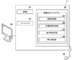
- 1 is a hardware configuration diagram showing an outline of a diagnosis support system to which an image display device according to a first embodiment of the present invention is applied.
- 1 is a schematic block diagram showing the configuration of an image display device according to a first embodiment. Diagram showing the result of feature point detection and matching The figure for demonstrating determination of the nearest edge part in 1st Embodiment The figure which shows the tentative top, bottom, left and right edges set in the tomographic image The figure which shows the common area
- the figure for demonstrating the determination of the nearest edge part in 2nd Embodiment The figure which shows the common area
- the figure which shows the tomographic image in which the binarization process was performed in 4th Embodiment The schematic block diagram which shows the structure of the image display apparatus by 5th Embodiment.
- FIG. 1 is a hardware configuration diagram showing an outline of a diagnosis support system to which the image display device according to the first embodiment of the present invention is applied.
- the image display device 1, the three-dimensional image capturing device 2, and the image storage server 3 according to the present embodiment are connected in a communicable state via a network 4.
- the diagnosis support system the current three-dimensional image and the past three-dimensional image are displayed on the image display device 1 for comparative diagnosis of a part to be diagnosed of the subject.
- the three-dimensional image photographing apparatus 2 is an apparatus that generates a three-dimensional image representing a part by photographing a part to be diagnosed of a subject. Specifically, a CT apparatus, an MRI apparatus, and a PET apparatus. Etc.
- the three-dimensional image V0 generated by the three-dimensional image photographing device 2 is transmitted to the image storage server 3 and stored.
- the diagnosis target part of the subject is the cervical vertebra
- the three-dimensional image capturing apparatus 2 is a CT apparatus, and a three-dimensional image composed of tomographic images of a plurality of axial sections about the cervical vertebra of the subject. Shall be generated.
- the image storage server 3 is a computer that stores and manages various data, and includes a large-capacity external storage device and database management software.
- the image storage server 3 communicates with other devices via a wired or wireless network 4 to transmit and receive image data and the like.
- image data such as a three-dimensional image generated by the three-dimensional image capturing device 2 is acquired via a network, stored in a recording medium such as a large-capacity external storage device, and managed.
- image data storage format and communication between devices via the network 4 are based on a protocol such as DICOM (Digital Imaging and Communication in Medicine).
- DICOM Digital Imaging and Communication in Medicine
- the image display device 1 is obtained by installing the image display program of the present invention on one computer.
- the computer may be a workstation or personal computer directly operated by a doctor who performs diagnosis, or may be a server computer connected to them via a network.
- the image display program is recorded and distributed on a recording medium such as a DVD (Digital Versatile Disc) or a CD-ROM (Compact Disk Read Only Memory), and is installed in the computer from the recording medium.
- a recording medium such as a DVD (Digital Versatile Disc) or a CD-ROM (Compact Disk Read Only Memory)
- it is stored in a storage device of a server computer connected to a network or a network storage in a state where it can be accessed from the outside, and is downloaded and installed on a computer used by a doctor upon request.
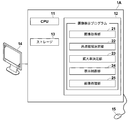
- FIG. 2 is a diagram showing a schematic configuration of an image display apparatus realized by installing an image display program in a computer.
- the image display device 1 includes a CPU (Central Processing Unit) 11, a memory 12, and a storage 13 as a standard workstation configuration.
- the image display device 1 is connected to a display 14 and an input unit 15 such as a mouse.
- the display 14 corresponds to display means.
- the storage 13 stores various information including current and past three-dimensional images of the same subject acquired from the image storage server 3 via the network 4 and information necessary for processing.
- the latest three-dimensional image (hereinafter referred to as the current three-dimensional image V1) for the same subject and the three-dimensional images V2 and V3 acquired at different times in the past are stored. It shall be.
- the three-dimensional image may be collectively referred to as a three-dimensional image V0.
- the memory 12 stores an image display program.
- the image display program is a process to be executed by the CPU 11, and the corresponding axial tomographic plane to be diagnosed in the three-dimensional images V1 to V3 including the cervical vertebrae to be diagnosed for comparative interpretation acquired by the three-dimensional imaging device 2 is used.
- Image acquisition processing for acquiring tomographic images T1 to T3, common region determination processing for determining common regions existing in common among tomographic images T1 to T3, and display of a plurality of common regions for tomographic images T1 to T3 in the same size
- Applying the enlargement factor determination process for determining the enlargement factor for each of the tomographic images T1 to T3 and the enlargement factor determined for the plurality of common regions, and displaying the images of the plurality of common regions after applying the enlargement factor 14 specifies the display control processing to be displayed.
- the image display device 1 may include a plurality of processors that respectively perform image acquisition processing, common area determination processing, enlargement ratio determination processing, and display control processing.
- the tomographic images T1 to T3 correspond to medical images.
- the image acquisition unit 21 acquires from the image storage server 3 the tomographic images T1 to T3 of the corresponding axial tomographic planes to be diagnosed in the three-dimensional images V1 to V3. Note that the image acquisition unit 21 may acquire the three-dimensional images V1 to V3 from the image storage server 3 and acquire the tomographic images T1 to T3 from the three-dimensional images V1 to V3. If the three-dimensional images V1 to V3 are already stored in the storage 13, the tomographic images T1 to T3 may be acquired from the storage 13.
- the common area determination unit 22 determines a common area that exists in common in the tomographic images T1 to T3.
- the common region determination unit 22 extracts feature points from each of the tomographic images T1 to T3, and determines the common region by matching the extracted feature points. First, feature point extraction and matching will be described.
- a feature point and a region of, for example, 9 ⁇ 9 pixels centered on the feature point are extracted as a template, and template matching is performed by searching for a corresponding feature point between tomographic images using the extracted template.
- template matching is performed by searching for a corresponding feature point between tomographic images using the extracted template.
- feature points such as edges, edge intersections, and edge corners included in tomographic images T1 to T3 are detected using algorithms such as SIFT (Scale-Invariant Feature Transform) or SURF (Speeded Up Robust Features).
- SIFT Scale-Invariant Feature Transform
- SURF Speeded Up Robust Features
- SIFT is a technique in which feature quantities that are invariant to image rotation and scale changes are described at feature points, and a plurality of images are aligned based on the described feature quantities.
- SURF is a technique for performing alignment at higher speed by replacing the processing performed in SIFT with approximation processing.
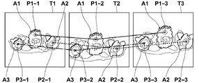
- FIG. 3 is a diagram showing the results of feature point detection and matching.
- the three tomographic images T1 to T3 include a cervical spine region A1 and shoulder regions A2 and A3, respectively.
- the cervical spine region A1 and shoulder regions A2 and A3 Included positions and sizes are different.
- the common region determination unit 22 detects a feature point P1-1 in the cervical vertebra region A1, a feature point P2-1 in the shoulder region A2, and a feature point P3-1 in the shoulder region A3 in the tomographic image T1, The feature points are matched between the images T1 to T3.
- the feature points P3-1, P3-2, and P3-3 in the shoulder region A3 are matched.
- the feature points P1-1, P1-2, and P1-3 are matched with a solid line, and the feature points P2-1, P2-2, and P2-3 are matched with a broken line.
- the fact that the points P 3-1, P 3-2 and P 3-3 are matched is indicated by a one-dot chain line.
- FIG. 3 only three feature points are detected in each of the tomographic images T1 to T3, but in reality, a large number of feature points are detected and matched.
- the common area determination unit 22 determines the top, bottom, left, and right edges closest to the matched feature points in the tomographic images T1 to T3 based on the result of feature point matching.
- the upper, lower, left, and right edges closest to the matched feature points in the tomographic images T1 to T3 are referred to as the nearest upper edge, the nearest lower edge, the nearest left edge, and the nearest right edge.
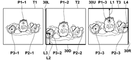
- FIG. 4 is a diagram for explaining the determination of the nearest edge portion. First, in order to determine the nearest upper edge, the common area determination unit 22 calculates the distances between all feature points and the upper edge in each of the tomographic images T1 to T3.
- the upper edge of the tomographic image including the feature point having the smallest calculated distance is determined as the nearest upper edge.
- the common region determining unit 22 The upper edge is determined as the nearest upper edge 30U.
- the common area determination unit 22 calculates the distances between all feature points and the lower edge in each of the tomographic images T1 to T3. Then, the lower edge of the tomographic image including the feature point having the smallest calculated distance is determined as the nearest lower edge.
- the common region determining unit 22 since the distance between the feature point P3-2 in the tomographic image T2 and the lower edge of the tomographic image T2 is the smallest, the common region determining unit 22 The lower edge is determined as the nearest lower edge 30D.
- the common area determining unit 22 determines the nearest left edge and the nearest right edge.
- the common region determining unit 22 sets the left edge of the tomographic image T2 to the left of the nearest neighbor.
- the edge 30L is determined.
- the common region determination unit 22 changes the right edge of the tomographic image T3 to the nearest right edge 30R. decide. In FIG. 4, the determined top, bottom, left, and right nearest edges are indicated by bold lines.
- the common area determination unit 22 determines the common areas in the tomographic images T1 to T3 based on the determined vertical and horizontal nearest edges. In the present embodiment, the common area is rectangular. First, determination of the upper edge of the common area will be described. In the present embodiment, since the upper edge portion of the tomographic image T3 is determined as the nearest upper edge portion 30U, the common region determining unit 22 determines the nearest upper edge portion 30U from the feature point P1-3 in the tomographic image T3. Distance L1 is calculated, and a temporary upper edge is set at a position away from the feature points P1-1 and P1-2 by a distance L1 with respect to the tomographic images T1 and T2.
- the distance L1 is normalized and provisional Set the upper edge. For example, the ratio of the distance between the feature point P1-1 and the feature point P3-1 in the tomographic image T1 to the distance between the feature point P1-3 and the feature point P3-3 in the tomographic image T3 is calculated, and the calculated ratio is After multiplying the distance L1, a temporary upper edge is set for the tomographic image T1.
- the ratio of the distance between the feature point P1-2 and the feature point P3-2 in the tomographic image T2 to the distance between the feature point P1-3 and the feature point P3-3 in the tomographic image T3 is calculated, and the calculated ratio Is multiplied by the distance L1, and a temporary upper edge is set for the tomographic image T2.
- the lower edge of the tomographic image T2 is determined as the nearest lower edge 30D. Therefore, the common area determining unit 22 uses the feature points in the tomographic image T2. A distance L2 from P3-2 to the nearest lower edge 30D is calculated, and a temporary lower edge is set at a position away from the feature points P3-1 and P3-2 by a distance L2 with respect to the tomographic images T2 and T3. To do. At this time, since the size of the subject area included in each of the tomographic images T1 to T3 is different, the distance L2 is normalized and the temporary lower edge is set as in the case of setting the temporary upper edge.
- the common area determining unit 22 uses the feature points in the tomographic image T2.
- a distance L3 from P3-2 to the nearest left edge 30L is calculated, and a temporary left edge is set at a position away from the feature points P3-1 and P3-2 by a distance L3 with respect to the tomographic images T2 and T3.
- the distance L3 is normalized similarly to the setting of the temporary upper edge, and the temporary left edge is set.
- the common region determining unit 22 determines the feature points in the tomographic image T3.
- a distance L4 from P2-3 to the nearest right edge 30R is calculated, and a temporary right edge is set at a position away from the feature points P2-1 and P2-2 by a distance L4 with respect to the tomographic images T1 and T2.
- the distance L4 is normalized similarly to the setting of the temporary upper edge, and the temporary right edge is set.
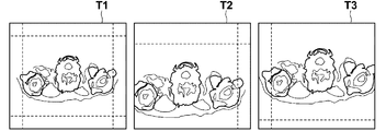
- Temporary vertical and horizontal edges set in the tomographic images T1 to T3 are indicated by broken lines in FIG.
- the common area determining unit 22 is defined by the upper, lower, left, and right temporary edges and the upper, lower, left, and right nearest edges of each tomographic image in each of the tomographic images T1 to T3.
- the common area is adjusted by adjusting the positions of the upper, lower, left, and right temporary edges and the upper, lower, left, and right nearest edges of each tomographic image so that the aspect ratio of the area surrounded by the frame is the same as the image to be displayed.
- FIG. 6 is a diagram showing the determined common area. As shown in FIG. 6, the tomographic images T1 to T3 show the determined common areas C1 to C3.
- the lower edge portion is located slightly above the nearest lower edge portion 30D.
- the upper edge portion is located slightly below the nearest upper edge portion 30U.
- the enlargement ratio determining unit 23 determines an enlargement ratio for displaying the common areas C1 to C3 with the same size for each of the tomographic images T1 to T3.
- the enlargement ratios R1 to R3 for enlarging and reducing the common areas C1 to C3 are determined for each of the tomographic images T1 to T3 so as to match the size of the image to display the common areas C1 to C3. To do. If the size of the common area is the same as the size of the image to be displayed, the enlargement ratio for the common area is 1, and neither enlargement nor reduction is practically performed.
- the display control unit 24 applies the determined enlargement ratios R1 to R3 to the common areas C1 to C3, respectively, and displays the images of the common areas C1 to C3 after applying the enlargement ratio on the display 14. That is, the common areas C1 to C3 are enlarged or reduced by the enlargement ratios R1 to R3, respectively, and the enlarged or reduced common area images G1 to G3 are displayed on the display 14.
- FIG. 7 is a diagram showing the images G1 to G3 of the common area displayed on the display 14. As shown in FIG. As shown in FIG. 7, the images G1 to G3 of the common area having the same size are displayed side by side. In the displayed images G1 to G3 of the common area, the cervical vertebra area A1 and the shoulder areas A2 and A3 are included in substantially the same position and in almost the same size.
- the positions of the subject areas in the common areas C1 to C3 or the positions where the subject area is interrupted by the frames are taken into consideration, so that the positions of the frames in the common areas C1 to C3 are set.
- the images G1 to G3 in the common area may be displayed with a certain margin.
- the tomographic images T1 to T3 in which the common areas C1 to C3 are set are displayed, and a correction instruction by the user is received, whereby the positions of the common areas C1 to C3 are received.
- the images G1 to G3 of the common area may be displayed after correcting the size.
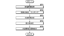
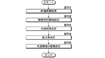
- FIG. 8 is a flowchart showing the processing performed in the first embodiment.
- the image acquisition unit 21 acquires tomographic images T1 to T3 (step ST1)
- the common area determination unit 22 extracts and matches feature points from the tomographic images T1 to T3 (step ST2). Based on the extraction and matching results, common regions C1 to C3 that are commonly present in the tomographic images T1 to T3 are determined (step ST3).
- the enlargement ratio determining unit 23 determines an enlargement ratio for displaying the common areas C1 to C3 with the same size for each of the tomographic images T1 to T3 (step ST4).
- the display control unit 24 applies the magnifications R1 to R3 determined for the common regions C1 to C3, respectively, and displays the images G1 to G3 of the common regions C1 to C3 after applying the magnifications on the display 14. (Step ST5), the process ends.
- the common areas C1 to C3 existing in common among the plurality of tomographic images T1 to T3 are determined, and the enlargement ratio for displaying the common areas C1 to C3 with the same size.
- R1 to R3 are determined for each of the plurality of tomographic images T1 to T3, and the magnifications R1 to R3 determined for the plurality of common regions C1 to C3 are applied to display the images G1 to G3 of the common region. It is a thing. Therefore, even if the user does not perform any processing, the display 14 displays the images G1 to G3 of the common area of the same size for the tomographic images T1 to T3. Therefore, it is possible to effectively make it easy to see the site to be diagnosed included in the plurality of tomographic images T1 to T3 to be compared.
- the acquired tomographic images T1 to T3 are images of one tomographic plane in the three-dimensional images V1 to V3, respectively, and therefore the positions of the tomographic planes of the displayed images G1 to G3 are displayed. Is changed, tomographic images of different tomographic planes are displayed. At that time, in the tomographic images of different tomographic planes, the same region as the common region, that is, the region having the same position and the same size as the common region set in the tomographic images T1 to T3 is cut out and enlarged to the size of the image to be displayed. What is necessary is just to reduce and display.
- a common area is determined between the tomographic images of the corresponding tomographic planes in the same manner as described above, and the tomographic planes that are switched when the tomographic planes are switched. You may display the image of the common area
- the configuration of the image display device according to the second embodiment is the same as the configuration of the image display device according to the first embodiment shown in FIG. 2, and only the processing performed by the common area determination unit 22 is different. A detailed description of the apparatus is omitted.
- an anatomical region common to tomographic images is extracted from tomographic images included in each of a plurality of three-dimensional images, and the common region is determined based on the extracted anatomical regions. This is different from the first embodiment.
- the common region determination unit 22 extracts an anatomical region from the tomographic image.
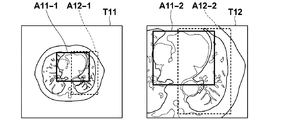
- FIG. 9 is a diagram for explaining extraction of an anatomical region from a tomographic image in the second embodiment.
- axial sectional tomographic images T11 and T12 included in the three-dimensional image of the chest are used.
- the common region determination unit 22 extracts the heart region and the lung region as anatomical regions from the tomographic images T11 and T12.
- a method of performing heart recognition and extracting the heart based on the recognition result can be used.
- the method described in Japanese Patent Application Laid-Open No. 2008-259682 normalizes an input tomographic image, calculates a large number of feature values from the normalized tomographic image, and calculates feature values for each normalized tomographic image. Is input to the discriminator obtained by the AdaBoost method, the score for each part representing the part-likeness is calculated, and the calculated part score is used as an input to arrange the body parts of the human body using dynamic programming.
- a signal value for each pixel in the tomographic image is formed into a histogram and extracted by thresholding the lung, a region expansion method based on a seed point representing the lung (Region (Growing), etc. Any method can be used.
- a region expansion method based on a seed point representing the lung (Region (Growing), etc. Any method can be used.
- only the right lung is targeted for extraction.
- the common region determination unit 22 extracts rectangular regions including the heart and lungs extracted in the tomographic images T11 and T12 as heart regions A11-1 and A11-2 and lung regions A12-1 and A12-2, respectively.
- the heart regions A11-1 and A11-2 are indicated by solid lines
- the lung regions A12-1 and A12-2 are indicated by broken lines.
- the heart regions A11-1 and A11-2 and the lung regions A12-1 and A12-2 correspond to anatomical regions.
- the common region determination unit 22 determines the top, bottom, left, and right edges closest to the extracted heart region and lung region, that is, the nearest edge portion, in the tomographic images T11 and T12. To do.
- both the heart region A11-2 and the lung region A12-2 are more in the tomographic image T12 than the heart region A11-1 and the lung region A12-1 in the tomographic image T1.
- the distance to the upper edge, the lower edge, the left edge, and the right edge is small. For this reason, as shown in FIG.
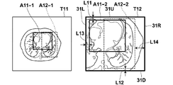
- the common region determination unit 22 sets the upper edge portion, the lower edge portion, the left edge portion, and the right edge portion of the tomographic image T12 as the nearest upper edge portion 31U and the nearest lower edge portion, respectively.
- the portion 31D, the nearest left edge 31L, and the nearest right edge 31R are determined.
- the common area determination unit 22 determines a common area that exists in common in the tomographic images T11 and T12, based on the determined top, bottom, left, and right nearest edge portions.
- the top, bottom, left and right edges of the tomographic image T12 are determined as the nearest upper edge 31U, the nearest lower edge 31D, the nearest left edge 31L, and the nearest right edge 31R. Therefore, the entire area of the tomographic image T12 becomes the common area C12.
- the common area determination unit 22 sets the frame of the common area C11 only for the tomographic image T11. Specifically, in the tomographic image T12, a distance L11 from the upper edge of the heart region A11-2 to the upper edge of the tomographic image T12 is calculated.
- the size ratio between the heart region A11-1 in the tomographic image T11 and the heart region A11-2 in the tomographic image T12 is calculated.
- the distance L11 is normalized by the calculated ratio, and the temporary upper edge is set at a position away from the upper edge of the heart region A11-1 in the tomographic image T11 by the normalized distance L11.
- a distance L12 from the lower edge of the lung area A12-2 to the lower edge of the tomographic image T12 is calculated in the tomographic image T12.
- the distance L12 is normalized as in the case of setting the temporary upper edge, and the temporary lower edge is placed at a position away from the normalized lower edge of the lung region A12-1 in the tomographic image T11 by the distance L12. Set.
- a distance L13 from the left edge of the heart region A11-2 to the left edge of the tomographic image T12 is calculated in the tomographic image T12.
- the distance L13 is normalized in the same manner as in the case of setting the temporary upper edge, and the temporary left edge is positioned at a position away from the normalized distance L13 from the left edge of the heart region A11-1 in the tomographic image T11.
- a distance L14 from the right edge of the lung area A12-2 to the right edge of the tomographic image T12 is calculated in the tomographic image T12.
- the distance L14 is normalized as in the case of setting the temporary upper edge, and the temporary right edge is positioned at a position away from the normalized distance L14 from the right edge of the lung region A12-1 in the tomographic image T11.
- the common area determination unit 22 is defined by the upper, lower, left, and right temporary edges and the upper, lower, left, and right nearest edges of each tomographic image in each of the tomographic images T11 and T12.
- the common area is adjusted by adjusting the positions of the upper, lower, left, and right temporary edges and the upper, lower, left, and right nearest edges of each tomographic image so that the aspect ratio of the area surrounded by the frame is the same as the image to be displayed.
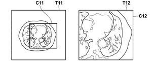
- FIG. 11 is a diagram showing the determined common area. As shown in FIG. 11, the determined common areas C11 and C12 are shown in the tomographic images T11 and T12. Note that the entire area of the tomographic image T12 is the common area C12.
- the enlargement ratio determining unit 23 determines an enlargement ratio for displaying the common areas C11 and C12 with the same size for each of the tomographic images T11 and T12. Further, the display control unit 24 applies the determined enlargement ratio to the common areas C11 and C12, respectively, and displays the images of the common areas C11 and C12 after applying the enlargement ratio on the display 14.
- FIG. 12 is a diagram showing an image of the common area displayed on the display 14 in the second embodiment. As shown in FIG. 12, images G11 and G12 in the common area are displayed side by side. In the displayed images G11 and G12 of the common region, the heart region and the lung region are included in substantially the same position and in substantially the same size.
- the subject area when displaying the images G11 and G12 in the common area, the subject area is interrupted by the arrangement or frame of the subject area in the common areas C11 and C12.
- the images G11 and G12 of the common areas C11 and C12 may be displayed with a certain margin for the position of each side of the frame.
- the tomographic images T111 and T12 in which the common areas C11 and C12 are set are displayed, and the correction instruction by the user is received, whereby the positions of the common areas C11 and C12 are displayed.
- the images G11 and G12 in the common area may be displayed after correcting the size.
- FIG. 13 is a flowchart showing processing performed in the second embodiment.
- the image acquisition unit 21 acquires tomographic images T11 and T12 (step ST11), and the common region determination unit 22 extracts anatomical regions from the tomographic images T11 and T12 (step ST12). Based on the extraction result of the target region, common regions C11 and C12 that are present in common in the tomographic images T11 and T12 are determined (step ST13).
- the enlargement ratio determining unit 23 determines an enlargement ratio for displaying the common areas C11 and C12 with the same size for each of the tomographic images T11 and T12 (step ST14).
- the display control unit 24 applies the enlargement ratios applied to the common areas C11 and C12, displays the images of the common areas C11 and C12 after applying the enlargement ratio on the display 14 (step ST15), and ends the processing. To do.
- the heart region and the lung region are extracted from the tomographic images T11 and T12, respectively, but only one of the heart region and the lung region, for example, only the heart region is extracted. May be.
- this will be described as a third embodiment.
- the positional relationship between the heart and the lung is almost constant regardless of the time when the three-dimensional image is taken. For this reason, in each tomographic image T11, T12, the anatomical positional relationship between the heart region and the lung region is known. Therefore, if the position of the lung region with respect to the extracted heart region A11-1 is known in one tomographic image T11, the position of the lung region can be known from the position of the heart region A11-2 in the other tomographic image T12.
- the common region determination unit 22 extracts the heart region A11-1 and the lung region A12-1 only in the tomographic image T11, and the lung for the heart region A11-1 in the tomographic image T1. Based on the position of the region A12-1, the position of the lung region relative to the heart region A11-2 in the other tomographic image T12 is specified. Thus, the position of the lung region in the tomographic image T12 can be determined from the positional relationship between the heart region A11-1 and the lung region A12-1 in the tomographic image T11 without extracting the lung region in the tomographic image T12. it can. Therefore, the common regions C11 and C12 can be determined from the heart region and the lung region in the tomographic images T11 and T12 in the same manner as described above.
- the configuration of the image display device according to the fourth embodiment is the same as the configuration of the image display device according to the first embodiment shown in FIG. 2, and only the processing performed by the common area determination unit 22 is different. A detailed description of the apparatus is omitted.
- the fourth embodiment at least a part of a subject area included in each of a plurality of three-dimensional images is extracted, and at least a part of the extracted subject area is aligned between tomographic images. This is different from the first embodiment in that the common region is determined by the above.
- the subject area is an area where a subject to be imaged in the tomographic image exists.
- the common area determination unit 22 extracts at least a part of the subject area included in the tomographic image. In the present embodiment, the entire subject area is extracted. Specifically, a technique for extracting a subject area by analyzing a histogram of a tomographic image, a technique for extracting a subject area by extracting a contour included in the tomographic image, or the like can be used. Furthermore, the common area determination unit 22 performs binarization processing on the tomographic image, thereby separating the tomographic image into a subject area and other areas.
- FIG. 14 is a diagram illustrating a tomographic image on which binarization processing has been performed. FIG.
- FIG. 14 shows a result obtained by extracting a subject region from the tomographic images T1 to T3 in the first embodiment and binarizing. As shown in FIG. 13, the subject areas A21, A22, A23 are separated from the other background areas from the tomographic images T1 to T3.
- the common area determination unit 22 performs translation, rotation, and enlargement / reduction of the binarized subject areas A21, A22, and A23, and aligns the subject areas A21, A22, and A23. Based on the alignment result, the common area determination unit 22 determines the top, bottom, left, and right edges closest to the aligned subject area in the tomographic images T1 to T3. Note that the determination of the top, bottom, left, and right nearest edge portions is the same as in the first embodiment, and a detailed description thereof is omitted here. In the fourth embodiment, instead of the feature points, the uppermost pixel position, the lowermost pixel position, and the leftmost pixel of the subject areas A21, A22, A23 in the tomographic images T1 to T3.
- the common area determination unit 22 determines temporary upper, lower, left, and right edges as in the first embodiment, and determines a common area.
- a common area may be set by extracting only a part of the subject area in the tomographic image. For example, only the cervical spine region in the tomographic images T1 to T3 may be extracted, and a common region including only the cervical spine region may be set.
- the alignment may be performed using the extracted subject area without performing the binarization process.
- FIG. 15 is a schematic block diagram showing a configuration of an image display device according to the fifth embodiment of the present invention.
- the same components as those in FIG. 1 are denoted by the same reference numerals, and detailed description thereof is omitted.
- the image display apparatus 1A according to the fifth embodiment is different from the first embodiment in that the image display apparatus 1A includes an image processing unit 25 that performs image processing for matching the image quality of images in a common area.
- the image processing unit 25 performs image processing for matching the density, contrast, and the like of the image in the common area on at least one of the plurality of common areas.
- the density the average density of the images in the plurality of common areas may be calculated, and the density of the images in the other common areas may be changed so as to match the average density of the image in any one of the common areas.
- the difference value between the highest density and the lowest density for each of the images of the plurality of common areas is calculated, and the image of the other common area is matched with the above difference value of the image of any one common area.
- the contrast may be changed so as to change the difference value.
- the common area may be determined after matching the actual sizes of the tomographic images.
- pixel spacing information of a tomographic image that is, information on the distance between the centers of adjacent pixels is given to a three-dimensional image
- the actual size of the tomographic image is matched using the pixel spacing information, Good.
- the pixel spacing information of the tomographic image T11 is 1 mm and the pixel spacing information of the tomographic image T12 is 2 mm
- the vertical and horizontal sizes of the tomographic image T12 are respectively reduced to 1 ⁇ 2.
- the actual sizes of the tomographic image T11 and the tomographic image T12 can be matched.
- the common area can be determined efficiently.
- the images of the common areas for the plurality of tomographic images are displayed side by side, but the images of the plurality of common areas may be switched and displayed.
- the image of the common area may be switched according to an instruction from the input unit 15, or the image of the common area may be automatically switched every time a certain time elapses.
- the display target is a tomographic image.
- the present invention is not limited to this, and a medical image acquired by an ultrasonic diagnostic layer, an MRI apparatus, a PET apparatus, an X-ray imaging apparatus, or the like.
- the present invention can also be applied to the case where the object is displayed.
- all medical images to be subjected to comparative interpretation diagnosis are displayed.
- only a plurality of selected medical images among all medical images to be subjected to comparative interpretation diagnosis are displayed. You may make it display.
- the tomographic images T1 and T2 are selected from the tomographic images T1 to T3
- only the tomographic images T1 and T2 are determined the common area, the magnification rate, and the common.
- the image of the area may be displayed.
- the common region and the enlargement ratio may be determined for all medical images, and only the plurality of selected medical images may be displayed.
- the common region can be determined efficiently.
- one anatomical region is extracted from each of the plurality of medical images, and extracted from one medical image among the plurality of medical images. Determine other anatomical regions in other medical images other than one medical image based on one anatomical region and the positional relationship between other anatomical regions other than one anatomical region. Then, by determining a common region based on one anatomical region extracted from a plurality of medical images and another anatomical region, it is only necessary to specify a region for one medical image.
- the designated area can be determined as a common area in a plurality of medical images and displayed on the display means.
- a common area can be determined well.
Landscapes
- Engineering & Computer Science (AREA)
- Theoretical Computer Science (AREA)
- Physics & Mathematics (AREA)
- General Physics & Mathematics (AREA)
- Multimedia (AREA)
- Computer Vision & Pattern Recognition (AREA)
- Health & Medical Sciences (AREA)
- Medical Informatics (AREA)
- Life Sciences & Earth Sciences (AREA)
- General Health & Medical Sciences (AREA)
- Databases & Information Systems (AREA)
- Computing Systems (AREA)
- Artificial Intelligence (AREA)
- Evolutionary Computation (AREA)
- Software Systems (AREA)
- Biomedical Technology (AREA)
- Molecular Biology (AREA)
- Surgery (AREA)
- Animal Behavior & Ethology (AREA)
- Heart & Thoracic Surgery (AREA)
- Public Health (AREA)
- Veterinary Medicine (AREA)
- Radiology & Medical Imaging (AREA)
- Pathology (AREA)
- Optics & Photonics (AREA)
- Nuclear Medicine, Radiotherapy & Molecular Imaging (AREA)
- High Energy & Nuclear Physics (AREA)
- Biophysics (AREA)
- Human Computer Interaction (AREA)
- Apparatus For Radiation Diagnosis (AREA)
Abstract
L'invention concerne un dispositif, procédé et programme d'affichage d'image permettant de faciliter effectivement l'observation d'une pluralité d'images médicales en tant que sujets pour une lecture comparative de celles-ci. Une unité d'acquisition d'image (21) acquiert une pluralité d'images médicales, et une unité de détermination d'une zone partagée (22) détermine une zone partagée qui est présente chez chacune desdites images médicales. Une unité de détermination du rapport d'agrandissement (23) détermine, pour chacune des images médicales, un rapport d'agrandissement afin d'afficher une pluralité de zones partagées à la même taille pour la pluralité des images médicales. Une unité de commande d'affichage (24) applique le rapport d'agrandissement déterminé à la pluralité des zones partagées, et affiche une image de la pluralité des zones partagées auxquelles le rapport d'agrandissement est appliqué dans un dispositif d'affichage (14).
Priority Applications (1)
| Application Number | Priority Date | Filing Date | Title |
|---|---|---|---|
| US16/046,264 US10307124B2 (en) | 2016-03-09 | 2018-07-26 | Image display device, method, and program for determining common regions in images |
Applications Claiming Priority (2)
| Application Number | Priority Date | Filing Date | Title |
|---|---|---|---|
| JP2016-045137 | 2016-03-09 | ||
| JP2016045137A JP6525903B2 (ja) | 2016-03-09 | 2016-03-09 | 画像表示装置、方法およびプログラム |
Related Child Applications (1)
| Application Number | Title | Priority Date | Filing Date |
|---|---|---|---|
| US16/046,264 Continuation US10307124B2 (en) | 2016-03-09 | 2018-07-26 | Image display device, method, and program for determining common regions in images |
Publications (1)
| Publication Number | Publication Date |
|---|---|
| WO2017154640A1 true WO2017154640A1 (fr) | 2017-09-14 |
Family
ID=59790432
Family Applications (1)
| Application Number | Title | Priority Date | Filing Date |
|---|---|---|---|
| PCT/JP2017/007502 Ceased WO2017154640A1 (fr) | 2016-03-09 | 2017-02-27 | Dispositif, procédé et programme d'affichage d'image |
Country Status (3)
| Country | Link |
|---|---|
| US (1) | US10307124B2 (fr) |
| JP (1) | JP6525903B2 (fr) |
| WO (1) | WO2017154640A1 (fr) |
Families Citing this family (4)
| Publication number | Priority date | Publication date | Assignee | Title |
|---|---|---|---|---|
| JP7334900B2 (ja) * | 2019-05-20 | 2023-08-29 | 国立研究開発法人理化学研究所 | 判別装置、学習装置、方法、プログラム、学習済みモデルおよび記憶媒体 |
| US11367254B2 (en) * | 2020-04-21 | 2022-06-21 | Electronic Arts Inc. | Systems and methods for generating a model of a character from one or more images |
| CN120019403A (zh) | 2022-09-20 | 2025-05-16 | 富士胶片株式会社 | 显示控制装置、显示控制装置的工作方法及显示控制装置的工作程序 |
| US20260045007A1 (en) * | 2024-08-06 | 2026-02-12 | Fujifilm Healthcare Americas Corporation | System and method for synchronized navigation and annotation of correlated, heterogeneous sets of medical images |
Citations (7)
| Publication number | Priority date | Publication date | Assignee | Title |
|---|---|---|---|---|
| JPS6244224A (ja) * | 1985-08-23 | 1987-02-26 | 富士写真フイルム株式会社 | 画像処理方法および装置 |
| JP2002253540A (ja) * | 2001-02-27 | 2002-09-10 | Canon Inc | 医療用撮影システム及び撮影表示方法 |
| JP2003010172A (ja) * | 2001-07-04 | 2003-01-14 | Hitachi Medical Corp | 臓器の特定領域抽出表示方法及び装置 |
| JP2008188177A (ja) * | 2007-02-02 | 2008-08-21 | Hitachi Medical Corp | 画像処理装置 |
| JP2013202051A (ja) * | 2012-03-27 | 2013-10-07 | Hitachi Ltd | 内臓脂肪シミュレーション装置及びプログラム |
| JP2015213749A (ja) * | 2014-04-21 | 2015-12-03 | 株式会社東芝 | X線コンピュータ断層撮影装置及び撮影条件設定支援装置 |
| JP2016012346A (ja) * | 2014-06-04 | 2016-01-21 | パナソニック株式会社 | 制御方法及びプログラム |
Family Cites Families (10)
| Publication number | Priority date | Publication date | Assignee | Title |
|---|---|---|---|---|
| JP3639030B2 (ja) | 1995-02-28 | 2005-04-13 | 株式会社東芝 | 画像表示システム及びそのシステムを用いた画像表示方法 |
| JP2003265416A (ja) | 2002-03-12 | 2003-09-24 | Konica Corp | 医療画像処理装置 |
| JP4997341B2 (ja) | 2011-11-21 | 2012-08-08 | 株式会社東芝 | 医用画像表示装置 |
| KR20130111780A (ko) * | 2012-04-02 | 2013-10-11 | 삼성전자주식회사 | Emi 차폐부를 갖는 반도체 장치 |
| US20140021201A1 (en) * | 2012-06-14 | 2014-01-23 | RG Innovations, LLC | System and method for modular and interchangable human interface solutions for portable electronic devices |
| KR102114415B1 (ko) * | 2013-01-29 | 2020-05-22 | 삼성전자주식회사 | 의료 영상 정합 방법 및 장치 |
| JP6053012B2 (ja) * | 2013-03-28 | 2016-12-27 | 富士フイルム株式会社 | 画像表示装置および方法 |
| US9289772B2 (en) * | 2013-08-01 | 2016-03-22 | Storm Technologies, Inc. | System for improving airflow characteristics within a coal pulverizer |
| JP6419441B2 (ja) | 2014-03-11 | 2018-11-07 | キヤノンメディカルシステムズ株式会社 | 医用画像処理装置、医用画像処理システム、および医用画像処理プログラム |
| US9613181B2 (en) * | 2014-05-29 | 2017-04-04 | Globalfoundries Inc. | Semiconductor device structure including active region having an extension portion |
-
2016
- 2016-03-09 JP JP2016045137A patent/JP6525903B2/ja active Active
-
2017
- 2017-02-27 WO PCT/JP2017/007502 patent/WO2017154640A1/fr not_active Ceased
-
2018
- 2018-07-26 US US16/046,264 patent/US10307124B2/en active Active
Patent Citations (7)
| Publication number | Priority date | Publication date | Assignee | Title |
|---|---|---|---|---|
| JPS6244224A (ja) * | 1985-08-23 | 1987-02-26 | 富士写真フイルム株式会社 | 画像処理方法および装置 |
| JP2002253540A (ja) * | 2001-02-27 | 2002-09-10 | Canon Inc | 医療用撮影システム及び撮影表示方法 |
| JP2003010172A (ja) * | 2001-07-04 | 2003-01-14 | Hitachi Medical Corp | 臓器の特定領域抽出表示方法及び装置 |
| JP2008188177A (ja) * | 2007-02-02 | 2008-08-21 | Hitachi Medical Corp | 画像処理装置 |
| JP2013202051A (ja) * | 2012-03-27 | 2013-10-07 | Hitachi Ltd | 内臓脂肪シミュレーション装置及びプログラム |
| JP2015213749A (ja) * | 2014-04-21 | 2015-12-03 | 株式会社東芝 | X線コンピュータ断層撮影装置及び撮影条件設定支援装置 |
| JP2016012346A (ja) * | 2014-06-04 | 2016-01-21 | パナソニック株式会社 | 制御方法及びプログラム |
Also Published As
| Publication number | Publication date |
|---|---|
| JP6525903B2 (ja) | 2019-06-05 |
| JP2017158757A (ja) | 2017-09-14 |
| US20180325478A1 (en) | 2018-11-15 |
| US10307124B2 (en) | 2019-06-04 |
Similar Documents
| Publication | Publication Date | Title |
|---|---|---|
| JP5138431B2 (ja) | 画像解析装置および方法並びにプログラム | |
| JP5486197B2 (ja) | 椎骨中心検出装置および方法並びにプログラム | |
| Yao et al. | Automated spinal column extraction and partitioning | |
| US8417009B2 (en) | Apparatus, method, and computer readable medium for assisting medical image diagnosis using 3-D images representing internal structure | |
| US20200058098A1 (en) | Image processing apparatus, image processing method, and image processing program | |
| JP6363575B2 (ja) | 画像位置合わせ装置および方法並びにプログラム | |
| JP4744883B2 (ja) | 画像位置合わせ方法及び医用画像データ処理装置 | |
| JP5364290B2 (ja) | 画像表示装置並びに画像表示制御方法およびプログラム | |
| US8374410B2 (en) | Medical image display device and image displaying method | |
| CN112116004B (zh) | 病灶分类方法及装置、病灶分类模型的训练方法 | |
| JP4545807B2 (ja) | 骨番号認識装置およびそのプログラム | |
| TWI684994B (zh) | 脊椎影像註冊方法 | |
| JP2018061771A (ja) | 画像処理装置、及び画像処理方法 | |
| Forsberg | Atlas-based registration for accurate segmentation of thoracic and lumbar vertebrae in CT data | |
| JP6525903B2 (ja) | 画像表示装置、方法およびプログラム | |
| WO2011050454A1 (fr) | Appareil et procédé de segmentation d'imagerie osseuse | |
| JP2009207727A (ja) | 椎体位置決定装置および方法並びにプログラム | |
| JP2009301254A (ja) | 画像処理装置および方法ならびにプログラム | |
| Lenga et al. | Deep learning based rib centerline extraction and labeling | |
| JP2019088672A (ja) | 画像処理装置および画像処理装置の作動方法並びに画像処理プログラム | |
| JP4099357B2 (ja) | 画像処理方法および装置 | |
| JP7098835B2 (ja) | マッチング装置、方法およびプログラム | |
| Čech et al. | Piecewise rigid multimodal spine registration | |
| CN112190275A (zh) | 扫描方法、装置及系统 | |
| JP7574123B2 (ja) | 画像位置合わせ装置、方法およびプログラム |
Legal Events
| Date | Code | Title | Description |
|---|---|---|---|
| NENP | Non-entry into the national phase |
Ref country code: DE |
|
| 121 | Ep: the epo has been informed by wipo that ep was designated in this application |
Ref document number: 17762980 Country of ref document: EP Kind code of ref document: A1 |
|
| 122 | Ep: pct application non-entry in european phase |
Ref document number: 17762980 Country of ref document: EP Kind code of ref document: A1 |