WO2017154655A1 - Système d'identification de type de foule, procédé d'identification de type de foule et support de stockage permettant de stocker un programme d'identification de type de foule - Google Patents
Système d'identification de type de foule, procédé d'identification de type de foule et support de stockage permettant de stocker un programme d'identification de type de foule Download PDFInfo
- Publication number
- WO2017154655A1 WO2017154655A1 PCT/JP2017/007643 JP2017007643W WO2017154655A1 WO 2017154655 A1 WO2017154655 A1 WO 2017154655A1 JP 2017007643 W JP2017007643 W JP 2017007643W WO 2017154655 A1 WO2017154655 A1 WO 2017154655A1
- Authority
- WO
- WIPO (PCT)
- Prior art keywords
- crowd
- type
- local
- type identification
- staying
- Prior art date
- Legal status (The legal status is an assumption and is not a legal conclusion. Google has not performed a legal analysis and makes no representation as to the accuracy of the status listed.)
- Ceased
Links
Images





Classifications
-
- G—PHYSICS
- G06—COMPUTING OR CALCULATING; COUNTING
- G06T—IMAGE DATA PROCESSING OR GENERATION, IN GENERAL
- G06T7/00—Image analysis
- G06T7/20—Analysis of motion
- G06T7/246—Analysis of motion using feature-based methods, e.g. the tracking of corners or segments
-
- G—PHYSICS
- G06—COMPUTING OR CALCULATING; COUNTING
- G06F—ELECTRIC DIGITAL DATA PROCESSING
- G06F18/00—Pattern recognition
- G06F18/20—Analysing
- G06F18/23—Clustering techniques
-
- G—PHYSICS
- G06—COMPUTING OR CALCULATING; COUNTING
- G06F—ELECTRIC DIGITAL DATA PROCESSING
- G06F18/00—Pattern recognition
- G06F18/20—Analysing
- G06F18/24—Classification techniques
-
- G—PHYSICS
- G06—COMPUTING OR CALCULATING; COUNTING
- G06T—IMAGE DATA PROCESSING OR GENERATION, IN GENERAL
- G06T7/00—Image analysis
- G06T7/60—Analysis of geometric attributes
-
- G—PHYSICS
- G06—COMPUTING OR CALCULATING; COUNTING
- G06T—IMAGE DATA PROCESSING OR GENERATION, IN GENERAL
- G06T7/00—Image analysis
- G06T7/70—Determining position or orientation of objects or cameras
-
- G—PHYSICS
- G06—COMPUTING OR CALCULATING; COUNTING
- G06V—IMAGE OR VIDEO RECOGNITION OR UNDERSTANDING
- G06V20/00—Scenes; Scene-specific elements
- G06V20/50—Context or environment of the image
- G06V20/52—Surveillance or monitoring of activities, e.g. for recognising suspicious objects
- G06V20/53—Recognition of crowd images, e.g. recognition of crowd congestion
-
- G—PHYSICS
- G06—COMPUTING OR CALCULATING; COUNTING
- G06T—IMAGE DATA PROCESSING OR GENERATION, IN GENERAL
- G06T2207/00—Indexing scheme for image analysis or image enhancement
- G06T2207/10—Image acquisition modality
- G06T2207/10016—Video; Image sequence
-
- G—PHYSICS
- G06—COMPUTING OR CALCULATING; COUNTING
- G06T—IMAGE DATA PROCESSING OR GENERATION, IN GENERAL
- G06T2207/00—Indexing scheme for image analysis or image enhancement
- G06T2207/30—Subject of image; Context of image processing
- G06T2207/30196—Human being; Person
Definitions
- the present invention relates to a crowd type identification system, a crowd type identification method, and a storage medium for storing a crowd type identification program for identifying the type of a crowd shown in an image.
- Patent Document 1 describes a system for extracting the number of people in a queue.
- the system described in Patent Literature 1 extracts a person region in an image by a background difference method. Further, in the system described in Patent Document 1, a matrix detection area is predetermined in an image. The system described in Patent Document 1 extracts the number of people in a matrix for this detection area. With the technique described in Patent Document 1, it is possible to detect the type of crowd called “matrix” from within the detection region.
- Patent Document 2 describes a system for detecting a group having a high degree of abnormality.
- Patent Document 3 describes a system that detects a location where a person or the like stays in a moving image area.
- Patent Document 4 describes a crowd state recognition device that can recognize the number of people in various regions in an image and recognize the direction of the crowd in various regions in the image. Further, Patent Document 4 describes an apparatus that generates teacher data for obtaining a classifier dictionary used by the crowd state recognition apparatus when performing recognition processing by machine learning.
- the types of crowds that have stayed include, for example, “matrix” and “enclosure”. However, with the technique described in Patent Document 1, only “matrix” can be detected as the type of crowd from an image. It is preferable that various types can be identified as the types of staying crowds appearing in the image.
- the present invention provides a crowd type identification system, a crowd type identification method, and a storage medium for storing a crowd type identification program that can identify various types as the types of staying crowds appearing in an image. With the goal.
- a crowd type identification system includes a staying crowd detection unit that detects a local area indicating a staying crowd from local areas defined in an image acquired by an image acquisition device;
- the direction of the crowd is estimated by targeting the image corresponding to the local area detected by the crowd detection means, and the crowd direction estimation means for adding the direction of the crowd to the local area, and the crowd direction estimation means
- For a local region with an orientation use the relative vector that indicates the relative positional relationship between the two local regions and the direction of the crowds of the two local regions to determine the type of crowd that consists of multiple people
- a crowd type identifying means for identifying and outputting the type and position of the crowd.
- the crowd type identification system analyzes detection means for detecting a plurality of partial regions including a crowd that has stayed from the image, the first partial region and the second partial region, And an identification means for identifying the type of crowd of the first partial area and the second partial area.
- the crowd type identification method detects a local region indicating a staying crowd from local regions defined in an image acquired by an image acquisition device, and corresponds to the detected local region
- the direction of the crowd is estimated from the image of the part to be applied, the direction of the crowd is added to the local region, and the relative positional relationship between the two local regions is determined for the local region to which the direction of the crowd is added.
- the type of crowd composed of a plurality of people who stayed is identified, and the type and position of the crowd are output.
- a plurality of partial areas including a crowd that has stayed are detected from an image, the first partial area and the second partial area are analyzed, and the first partial area is analyzed.
- a type of crowd of the area and the second partial area is identified.
- the storage medium is a storage medium detection process for detecting a local area indicating a staying crowd from local areas defined in an image acquired by an image acquisition device.
- a crowd type identifying program for executing a crowd type identifying process for identifying a crowd type and outputting the crowd type and position is stored.
- the storage medium uses a computer to detect, from an image, a plurality of partial areas including a staying crowd, and a first partial area and a second partial area.
- a crowd type identification program for executing identification processing for identifying a crowd type of the first partial area and the second partial area is stored.
- One aspect of the present invention is also realized by a crowd type identification program stored in the above-described storage medium.
- various types can be identified as the types of staying crowds appearing in the image.
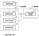
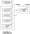
- FIG. 1 It is a block diagram which shows the structural example of the crowd kind identification system which concerns on the 1st Embodiment of this invention. It is a block diagram which shows the structural example of the staying crowd detection part which concerns on the 1st Embodiment of this invention. It is a block diagram which shows the structural example of the crowd direction estimation part which concerns on the 1st Embodiment of this invention. It is a block diagram which shows the structural example of the crowd kind identification part which concerns on the 1st Embodiment of this invention. It is a schematic diagram which shows the example of the relative vector which shows two selected local area
- FIG. 1 It is a block diagram which shows the structural example of the staying crowd detection part which concerns on the 1st Embodiment of this invention. It is a block diagram which shows the structural example of the crowd direction estimation part which concerns on the 1st Embodi
- FIG. 6 is a schematic diagram showing two local areas where the type of crowd is identified as surrounding. It is a flowchart which shows the example of operation
- FIG. 1 is a block diagram illustrating a configuration example of a crowd type identification system according to a first embodiment of this invention.
- the crowd type identification system according to the first embodiment of the present invention includes an image acquisition device 1, a data processing device 2 that operates under program control, and a storage device 3 that stores information.
- the image acquisition device 1 acquires an image from the output of an imaging device such as a camera or the output of a video device such as a video device.
- the storage device 3 includes a local region group storage unit 31.
- the local area group storage unit 31 stores the position and size of each local area arranged in the image.
- the position and size of each local area are determined in advance. Basically, the position and size of each local region are determined so that the entire image is covered by a plurality of local regions.
- the mode of determining the local area is not limited to the above example, and a plurality of local areas may be defined only for the area to be identified as a crowd type in the image. Further, the local region may be determined so that the local regions overlap each other.
- the size of the local region is determined in accordance with functions of a staying crowd detection unit 21 and a crowd direction estimation unit 22 which will be described later.
- a local area image an image of a portion corresponding to the local area in the image.
- the data processing apparatus 2 includes a staying crowd detection unit 21, a crowd direction estimation unit 22, and a crowd type identification unit 23.
- the staying crowd detection unit 21 acquires an image (acquired by the image acquisition device 1) by each predetermined local region (in other words, by the position and size of each local region stored in the local region group storage unit 31). For each local area image specified from (image), the staying degree of the object and the number of people in the local area are estimated. The staying degree of the object is a value indicating the staying state of the object. The number of people in the local area is a value indicating the density of the crowd. Based on the two values, the staying crowd detection unit 21 detects a local area indicating the staying crowd from each local area.
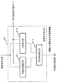
- FIG. 2 is a block diagram illustrating a configuration example of the staying crowd detection unit 21.
- the staying crowd detection unit 21 includes a staying state estimation unit 211, a number of people estimation unit 212, and a local region detection unit 213.
- the staying state estimation unit 211 estimates the staying degree of the object for each local region image specified from the image acquired by the image acquisition device 1 using each predetermined local region.
- an object means not only a crowd but various objects including a crowd.
- the staying state estimation unit 211 estimates the staying degree of the whole object including the crowd.
- the staying state estimation unit 211 may calculate the similarity of the feature amount of the image pattern, the motion vector, and the amount of inter-frame difference from the local region images having different times and the same place. It can be said that these values represent the degree of movement of the object shown in the local region.
- the similarity of the feature quantities of the image pattern has a property that the staying degree increases as the similarity degree increases.
- the motion vector has the property that the dwelling degree increases if the magnitude of the motion vector is small.
- the amount of difference between frames has the property that the dwelling degree increases if the value is small.
- the staying state estimating unit 211 may use these properties to estimate the staying degree of the object based on the calculated value.
- an estimator that outputs the staying degree of an object when a local region image having a different time and the same place is input may be obtained in advance by learning.
- the staying state estimating unit 211 may obtain an estimated value of the staying degree of the object by inputting local region images having different times and the same place to the estimator.
- two local area images with different times when the object stays, two local area images with different times when the object does not stay, and each of them In this case, information indicating the staying state of the object may be used. This learning can be said to be local region-based learning.
- a motion sensor that detects the movement of the object in the real space corresponding to the local area may be provided, and the staying state estimation unit 211 may estimate the staying degree of the object indicated by the local area image from the detection result of the motion sensor. .
- the method for estimating the staying degree may be a method other than the above-described method.
- the number-of-persons estimation unit 212 estimates the number of people in the local region for each local region image specified from the image acquired by the image acquisition device 1 using each predetermined local region.
- the number-of-people estimation unit 212 may estimate the number of people in the local region using an estimator obtained by learning. For example, when a local area image is input, an estimator that outputs the number of people in the local area is obtained in advance by learning. The number-of-people estimation unit 212 may obtain an estimated value of the number of people in the local region by inputting the local region image to the estimator. For the learning of the estimator, a local area image indicating a crowd composed of a plurality of persons and information on the number of persons corresponding to the local area image may be used. This learning can be said to be local region-based learning. This technique is also described in Patent Document 4.
- the method for estimating the number of people in the local area may be a method other than the above-described method.
- the local region detection unit 213 uses the degree of stay of the object estimated by the stay state estimation unit 211 and the number of people in the local region estimated by the number of people estimation unit 212, from among each predetermined local region. , To detect all local areas showing the crowd that has stayed. Specifically, all local regions in which the degree of stay of an object is greater than a predetermined threshold and the number of people in the local region is greater than a predetermined threshold are detected. It is assumed that the threshold regarding the staying degree and the threshold regarding the number of persons are set separately.
- the crowd direction estimation unit 22 estimates the crowd direction in the local region image corresponding to the local region detected by the staying crowd detection unit 21, and adds the crowd direction to the local region. Specifically, the crowd direction estimation unit 22 adds information indicating the crowd direction to the local region.
- the orientation of the crowd may be, for example, a direction in which a majority of people whose images are included in the local area are facing in a local area in the image.
- the orientation of the crowd may be, for example, a direction in which a majority of people whose images are included in the local region are facing in a local region in the image.
- the direction of the crowd may be, for example, a direction in which a majority of people whose images are included in the local area are focused on in the local area in the image.
- the direction of the crowd may be determined by the intention of a person who learns an estimator that estimates the direction of the crowd, as will be described later.
- the direction of the crowd is not limited to the above example.
- FIG. 3 is a block diagram illustrating a configuration example of the crowd direction estimation unit 22.
- the crowd direction estimation unit 22 includes a direction estimation unit 221 and a data addition unit 222.
- the direction estimation unit 221 estimates the crowd direction in the local region image corresponding to the local region detected by the staying crowd detection unit 21.
- the direction estimation unit 221 may estimate the crowd direction using an estimator obtained by learning. For example, when a local area image is input, an estimator that outputs a crowd direction in the local area image is obtained in advance by learning.
- the direction estimation unit 221 may estimate the crowd direction by inputting a local region image corresponding to the local region detected by the staying crowd detection unit 21 to the estimator.
- a local area image showing a crowd composed of a plurality of people in various directions and a vector or angle indicating the direction of a representative crowd corresponding to the local area image are used. Good. This learning can be said to be local region-based learning. This technique is also described in Patent Document 4.
- the method for estimating the direction of the crowd may be a method other than the above-described method.
- the data adding unit 222 adds information indicating the estimated crowd direction to the corresponding local region.
- the crowd type identification unit 23 executes the following processing for each combination of local regions including two local regions obtained from each local region to which information indicating the direction of the crowd is added.
- the crowd type identification unit 23 uses a vector indicating the relative positional relationship between two local areas forming a set, and information indicating the direction of the crowd added to each of the two local areas to Identifies the type of crowd that consists of people and identifies the location of the crowd.
- the crowd location is the location of the two local regions used to identify the crowd type.
- a vector indicating the relative positional relationship between two local regions is referred to as a relative vector.
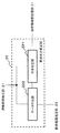
- FIG. 4 is a block diagram illustrating a configuration example of the crowd type identification unit 23.
- the crowd type identification unit 23 includes a relative vector calculation unit 231 and an analysis unit 232.
- the relative vector calculation unit 231 selects two local regions that form a pair. Then, the relative vector calculation unit 231 calculates a relative vector indicating the relative positional relationship between the two local regions.
- FIG. 5 is a schematic diagram illustrating an example of a relative vector indicating two selected local regions and a relative positional relationship between the two local regions.
- the relative vector is indicated by a dotted line.
- the direction of the crowd indicated by the information added to each local area is indicated by a solid line vector.
- the direction of the crowd indicated by the information added to the local area is simply referred to as the direction of the crowd of the local area.
- the analysis unit 232 uses the relative vector and the information indicating the direction of the crowd added to each of the two local areas to identify the type of crowd composed of a plurality of people who have stayed. Identify the appearing position. Examples of crowded types include crowds, enclosures, and hangouts.
- FIG. 6 is a schematic diagram showing two local areas in which the type of crowd that appears is identified as a matrix.
- the relative vector is indicated by a dotted line
- the direction of the crowd in each local area is indicated by a solid line vector.
- the relative vector calculation unit 231 selects two local regions from each local region to which information indicating the direction of the crowd is added. Here, it is assumed that two local regions # 1 and # 2 shown in FIG. 6 are selected.
- the relative vector calculation unit 231 calculates a relative vector connecting the centroid positions of the two selected local regions.
- a description will be given by taking, as an example, a relative vector starting from the centroid position of local region # 2 and ending with the centroid position of local region # 1.
- the relative vector calculation unit 231 calculates two relative vectors in opposite directions from two local regions, and the analysis unit 232 calculates the two relative vectors. Process each.
- the relative vector calculation unit 231 determines whether the magnitude of the relative vector obtained from the two local areas is equal to or less than a predetermined threshold value. When the magnitude of the relative vector is larger than the predetermined threshold (in other words, when two local regions are far), the analysis unit 232 does not perform processing on the two local regions, and the relative vector calculation unit 231 Select two local regions.
- the analysis unit 232 calculates the direction of the crowd of each of the two selected local regions and the relative vector. To identify the type of crowd (residual crowd) corresponding to the two local regions.
- the analysis unit 232 calculates the similarity between the direction of the crowd in the local region # 1 and the direction of the relative vector. The analysis unit 232 also calculates the similarity between the crowd direction and the relative vector direction in the local region # 2. Further, the analysis unit 232 calculates the similarity between the direction of the crowd in the local region # 1 and the direction of the crowd in the local region # 2.
- the analysis unit 232 identifies the types of crowds corresponding to the two local regions as “matrix” when all the three similarities are larger than a predetermined value.
- Each similarity described above may be a value obtained by any method as long as it is a value indicating the degree of similarity in direction.
- An inner product may be used when obtaining the similarity of orientations.
- the analysis unit 232 may normalize a vector representing a direction, and calculate the inner product of the two normalized vectors as the degree of similarity of the directions indicated by the two vectors.
- a relative vector starting from the centroid position of the local region # 2 and ending with the centroid position of the local region # 1, and a relative vector in the opposite direction is calculated.
- the analysis unit 232 calculates the above three similarities not only when focusing on the former relative vector but also when focusing on the latter relative vector. Then, when the three similarities are all greater than a predetermined value, the analysis unit 232 identifies the type of crowd corresponding to the two local regions as a “matrix”.
- the analysis unit 232 identifies the type of crowd corresponding to the two local regions as a “matrix”. For example, the type of crowd corresponding to two local regions may be determined as a “matrix”.
- the analysis unit 232 pays attention to a relative vector starting from the centroid position of the local region # 2 and ending with the centroid position of the local region # 1, and the types of crowds corresponding to the two local regions Is identified as a “matrix”. Accordingly, when attention is paid to a relative vector opposite to the relative vector shown in FIG. 6, even if the type of crowd corresponding to the two local regions cannot be identified as “matrix”, the analysis unit 232 does The type of crowd corresponding to the two local regions shown may be determined as a “matrix”.
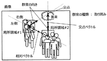
- FIG. 7 is a schematic diagram showing two local areas in which the type of crowd that appears is identified as an enclosure.
- the relative vector is indicated by a dotted line
- the direction of the crowd in each local region is indicated by a solid line vector.
- the relative vector calculation unit 231 selects two local regions from each local region to which information indicating the direction of the crowd is added. Here, it is assumed that two local regions # 1 and # 2 shown in FIG. 7 are selected.
- the relative vector calculation unit 231 calculates a relative vector connecting the centroid positions of the two selected local regions. In the “surrounding” identification process, the relative vector calculation unit 231 does not need to calculate two relative vectors in opposite directions from the two local regions.
- the relative vector calculation unit 231 may calculate one relative vector from two local regions.
- the relative vector calculation unit 231 may calculate a relative vector in any one direction.
- the direction of the relative vector can be arbitrarily selected from the two types. In the example shown in FIG. 7, a relative vector having the centroid position of the local region # 2 as a start point and the centroid position of the local region # 1 as an end point is illustrated.
- the relative vector calculation unit 231 determines whether the magnitude of the relative vector obtained from the two local areas is equal to or less than a predetermined threshold value. When the magnitude of the relative vector is larger than the predetermined threshold, the analysis unit 232 does not process the two local regions, and the relative vector calculation unit 231 newly selects two local regions. When the magnitude of the relative vector is equal to or smaller than a predetermined threshold (in other words, when the two local regions are close), the analysis unit 232 calculates the direction of the crowd of each of the two selected local regions and the relative vector. To identify the type of crowd (residual crowd) corresponding to the two local regions. This is the same as in the case of “matrix” identification processing.
- the analysis unit 232 calculates an outer product (hereinafter referred to as a first outer product) of the relative vector and the vector of the direction of the crowd in the local region # 1. Similarly, the analysis unit 232 calculates an outer product (hereinafter referred to as a second outer product) of the relative vector and the vector of the direction of the crowd in the local region # 2.
- the analysis unit 232 obtains an intersection of a straight line along the direction of the crowd in the local region # 1 and a straight line along the direction of the crowd in the local region # 2. Then, the analysis unit 232 calculates a vector having the intersection as the end point and the center of gravity of one of the two local regions (whichever is sufficient) as the start point. Hereinafter, for convenience, this vector is referred to as an intersection vector. In FIG. 7, the intersection vector is indicated by a broken line. In the example shown in FIG. 7, the center of gravity position of the local region # 2 is set as the starting point of the intersection vector. The analysis unit 232 calculates an outer product of the relative vector and the intersection vector (hereinafter referred to as a third outer product).
- the first outer product, the second outer product, and the third outer product are oriented in one of two directions perpendicular to the image. If the first outer product direction, the second outer product direction, and the third outer product direction are the same, the analysis unit 232 identifies the type of crowd corresponding to the two local regions as “surround”. To do.
- the direction of the first outer product and the direction of the second outer product are the same.
- the direction of the crowd in the local region # 1 and the direction of the crowd in the local region # 2 are based on a straight line along the relative vector. Means facing the same side.
- the direction of the first outer product, the direction of the second outer product, and the direction of the third outer product are the same, which means that the above intersection exists in the direction of the crowd direction of the local region # 1.
- the analysis unit 232 may identify the enclosure by a method different from the above method. In addition, from the direction of the crowds of the two local regions # 1 and # 2, abnormal portions and attention points can also be known.
- the crowd type identifying unit 23 may identify other types of crowds by using a relative vector and the direction of the crowd of the two local regions for a combination of two local regions.
- the crowd type identification unit 23 may execute identification processing for each of a plurality of different types.
- the crowd type identification unit 23 including the unit 231 and the analysis unit 232 is realized by a processor such as a computer CPU (Central Processing Unit), for example.
- the CPU reads a crowd type identification program from a program recording medium such as a program storage device (not shown) of the computer, and as the staying crowd detection unit 21, crowd direction estimation unit 22, and crowd type identification unit 23 according to the program. It only has to work.
- FIG. 8 is a flowchart showing an example of processing progress of the first embodiment of the present invention.
- the image acquisition device 1 acquires an image from the output of an imaging device such as a camera or a video device such as a video device (step S1).
- the image acquisition device 1 When the staying state estimation unit 211 employs a method of using local region images having different times and the same place as the method of estimating the staying degree of the object, the image acquisition device 1 is an image showing the same place. What is necessary is just to acquire two images with different imaging times. Further, the image acquisition device 1 may store an image at a certain time in advance, and acquire one image at a time different from that time in step S1. When the staying state estimating unit 211 adopts a method using a motion sensor as an object staying degree estimating method, the image obtaining apparatus 1 may obtain one image in step S1.
- the staying crowd detection unit 21 determines the staying degree of the object and the number of people in the local area for each local area image determined from the image acquired in step S1 by each predetermined local area. presume. Further, the staying crowd detection unit 21 detects a local area indicating the staying crowd from each local area based on the staying degree of the object and the estimated value of the number of people in the local area (step S2).
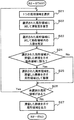
- FIG. 9 is a flowchart showing an example of processing progress of step S2.
- the staying state estimation unit 211 selects one local area that has not yet been selected from each predetermined local area (step S21). Each local area is represented by the position and size of each local area stored in the local area group storage unit 31. Note that steps S21 and S26 may be executed by the number-of-people estimation unit 212, but here, a case where the staying state estimation unit 211 executes steps S21 and S26 will be described as an example.
- the staying state estimating unit 211 estimates the staying degree of the object for the local region image specified from the image (the image acquired in step S1) by the local region selected in step S21 (step S22). . Since the example of the method for estimating the staying degree of the object has already been described, the description thereof is omitted here.
- the number estimating unit 212 estimates the number of people in the local region by targeting the local region image specified from the image (the image acquired in step S1) by the local region selected in step S21 ( Step S23). Since the example of the method for estimating the number of persons has already been described, the description is omitted here.
- steps S22 and S23 may be executed first.
- the local region detection unit 213 uses the degree of stay of the object estimated in step S22 and the number of people in the local region estimated in step S23 to indicate the crowd in which the selected local region has stayed. It is determined whether or not it is a local region (step S24).
- the fact that the selected local area is determined to be a local area indicating a staying crowd means that the local area detecting unit 213 has detected the selected local area as a local area indicating a staying crowd. It is.
- the local region detection unit 213 satisfies the condition that the degree of stay of an object is larger than a predetermined threshold and the number of people in the local region is larger than a predetermined threshold, and the selected local region is a crowd that has stayed. Is determined to be a local region. If the above condition is not satisfied, the local area detection unit 213 determines that the selected local area is not a local area indicating a crowd that has stayed.
- step S24 When the selected local region is a local region indicating a staying crowd (Yes in step S24), the local region detection unit 213 accumulates the selected local region as a local region indicating a staying crowd (step). S25). After step S25, the process proceeds to step S26.
- step S24 If the selected local area is not a local area indicating a staying crowd (No in step S24), the process proceeds to step S26 without performing step S25.
- step S26 the staying state estimation unit 211 determines whether or not there is an unselected local region (step S26). When there is an unselected local region (Yes in Step S26), the staying crowd detection unit 21 repeats the operations after Step S21.
- step S26 When there is no unselected local region (No in step S26), the local region detection unit 213 sends each local region indicating the crowd that has stayed (that is, each local region accumulated in step S25) to the crowd direction estimation unit 22. Output (step S27). By executing step S27, step S2 (see FIG. 8) is completed.
- the crowd direction estimation unit 22 estimates the direction of the crowd in the local area image corresponding to the local area for each local area indicating the staying crowd, and adds information indicating the direction of the crowd to the local area (Ste S3).
- the direction estimation unit 221 selects one local region from among the local regions indicating the staying crowd, and estimates the crowd direction in the local region image corresponding to the local region. Then, the data adding unit 222 adds information indicating the estimated crowd direction to the selected local region. The direction estimating unit 221 and the data adding unit 222 may perform the above processing until there is no unselected local region. Further, the data adding unit 222 outputs each local region to which information indicating the estimated crowd direction is added to the crowd type identifying unit 23.
- the crowd type identification unit 23 uses the relative vector and the crowd direction of the two local areas for each combination of local areas composed of two local areas to which information indicating the direction of the crowd is added. Identify the type of crowd that has stayed. In addition, the crowd type identification unit 23 identifies the position of the crowd. The crowd type identification unit 23 outputs the type of crowd and the position of the crowd (step S4). Examples of crowded types include crowds, enclosures, and hangouts. In step S4, the crowd type identification unit 23 may perform identification processing for one type, or may perform identification processing for a plurality of different types.
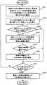
- FIG. 10 is a flowchart showing an example of the processing progress of step S4.
- the relative vector calculation unit 231 selects two local areas from among the local areas to which the information on the direction of the crowd is added (step S41).
- Step S41 can also be said to be a process of selecting one combination consisting of two local regions to which information on the direction of the crowd is added.
- the relative vector calculation unit 231 selects one unselected combination.
- the relative vector calculation unit 231 calculates a relative vector connecting the centroid positions of the two local regions selected in step S41 (step S42).
- the calculation mode of the relative vector may be different depending on the type of crowd to be subjected to the identification process. For example, when the type of crowd to be identified is “matrix”, the relative vector calculation unit 231 calculates two relative vectors in opposite directions. Further, for example, when the type of crowd to be subjected to identification processing is “surround”, the relative vector calculation unit 231 starts from the center of gravity of any one of the two local regions, It is only necessary to calculate one relative vector whose end point is the position of the center of gravity of the other local region.
- the relative vector calculation unit 231 determines whether or not the magnitude of the relative vector calculated in step S42 is equal to or less than a predetermined threshold (step S43).
- step S43 When the magnitude of the relative vector is larger than the predetermined threshold (No in step S43), the process proceeds to step S47.
- the analysis unit 232 uses the relative vector and the orientation of the crowds of the two selected local regions to determine the staying crowd.
- the type is identified (step S44).
- the analysis unit 232 may perform identification processing for one type, or may perform identification processing for a plurality of different types. For example, the analysis unit 232 may perform identification processing for only “matrix” or may perform identification processing for each of “matrix” and “surrounding” in step S44. Here, “matrix” and “surrounding” are illustrated, but the analysis unit 232 may perform identification processing for other types in step S44.
- step S44 If no crowd type has been identified in step S44 (No in step S45), the process proceeds to step S47.
- step S44 If at least one crowd type can be identified in step S44 (Yes in step S45), the analysis unit 232 accumulates the crowd type and the crowd position (step S46). The analysis unit 232 may accumulate the positions of the two local regions used for identifying the crowd type as the crowd positions. After step S46, the process proceeds to step S47.
- step S47 the relative vector calculation unit 231 determines whether or not all combinations of two local regions to which information on the direction of the crowd has been added have been selected (step S47). When there is an unselected combination (No in Step S47), the crowd type identifying unit 23 repeats the operations after Step S41.
- step S48 the analysis unit 232 outputs the accumulated crowd type and the crowd position (step S48).
- the output mode in step S48 is not particularly limited.
- the analysis unit 232 may display and output the type and position of the crowd, or may output in another manner.
- the crowd type identifying unit 23 sequentially selects a combination of local regions including two local regions with respect to the local region group indicating the staying crowd.
- the crowd type identification unit 23 identifies the type of the crowd using the relative vector and the direction of the crowd of each of the two local areas for the two local areas forming the selected combination. Therefore, various types can be identified as the types of staying crowds appearing in the image.
- a plurality of local areas are determined in advance.
- the crowd type identification unit 23 (more specifically, the analysis unit 232) identifies the type of the crowd for the two local regions that form the selected combination
- the position of the two local regions in the image is determined as follows: The position where the crowd appears in the image. Therefore, it is possible to specify the position in the image of the crowd whose type has been identified.
- local area based learning may be applied in learning for estimating the degree of stay of an object, learning for estimating the number of people in the local area, and learning for estimating the direction of the crowd. Moreover, you may learn using the image pattern containing the overlap of people. In this case, even if people are shown overlapping in the image acquired by the image acquisition device 1, the type of the crowd that has stayed can be identified robustly.
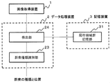
- FIG. 11 is a block diagram illustrating a modification of the first embodiment. The description of the same elements as those shown in FIG. 1 is omitted.
- the staying crowd detection unit 21 estimates the staying degree of objects in each local region and the number of people in the local region, and detects the local region indicating the staying crowd. Thereafter, the crowd direction estimation unit 22 (see FIG. 1) estimates the crowd direction with respect to the detected local region.
- the crowd type identification system shown in FIG. 11 simultaneously estimates the degree of object retention, the number of people in the local area, and the direction of the crowd for each predetermined local area.
- the crowd type identification system shown in FIG. 11 includes a detection unit 24 instead of the staying crowd detection unit 21 and the crowd direction estimation unit 22 shown in FIG.
- the detection unit 24 simultaneously estimates the staying degree of the object, the number of people in the local area, and the direction of the crowd for each predetermined local area.
- an estimator that outputs the degree of stay of an object, the number of people in the local region, and the direction of the crowd may be obtained in advance by learning.
- the detection unit 24 may obtain the estimation result of the staying degree of the object, the number of people in the local region, and the direction of the crowd at the same time by inputting the local region image to the estimator.
- you may use the technique of patent document 4 for learning of said estimator.
- the detection unit 24 is realized by, for example, a CPU of a computer that operates according to a crowd type identification program.
- the crowd type identification system according to the second embodiment of the present invention can be represented by the block diagram shown in FIG. 1 similarly to the crowd type identification system according to the first embodiment. An embodiment will be described.
- the staying crowd detection unit 21 and the crowd type identification unit 23 are the same as the staying crowd detection unit 21 and the crowd type identification unit 23 in the first embodiment, and a description thereof will be omitted.
- the crowd direction estimation unit 22 estimates the crowd direction in the local region image corresponding to the local region detected by the staying crowd detection unit 21, and determines the crowd direction when it is determined that the reliability of the crowd direction is high. The information shown is added to the local area. On the other hand, when it is determined that the reliability of the crowd direction is low, the crowd direction estimation unit 22 does not add the information indicating the crowd direction to the local area, and the local area is used for identifying the type of the crowd. Exclude from the target.
- the crowd direction estimation unit 22 in the second embodiment includes a direction estimation unit 221 and a data addition unit 222 as shown in FIG.
- the direction estimation unit 221 in the second embodiment estimates the crowd direction in the local region image corresponding to the local region detected by the staying crowd detection unit 21. This point is the same as in the first embodiment. However, the direction estimation unit 221 in the second embodiment estimates the direction of the crowd in such a manner that the reliability of the direction of the crowd can be determined by alternative.
- a vector indicating the direction of the crowd and representing the reliability of the direction in magnitude is output as the direction of the crowd in the local area image.
- An estimator is obtained in advance by regression learning.
- the direction estimation unit 221 estimates the crowd direction by inputting the local region image to the estimator. Since the estimation result of the crowd direction is obtained as the above-described vector, it is possible to determine whether the reliability of the crowd direction is high or low.
- the data adding unit 222 determines that the reliability of the estimated direction of the crowd is high, and information indicating the direction of the crowd (this book) In the example, information represented by a vector) may be added to the local region. If the magnitude of the vector indicating the direction of the crowd is less than a predetermined threshold, the data adding unit 222 determines that the reliability of the estimated direction of the crowd is low, and sets the crowd in a local area corresponding to the estimation result. The information indicating the direction of the is not added. The data adding unit 222 excludes the local area to which the information indicating the direction of the crowd is not added from the processing target of the crowd type identifying unit 23.
- an estimator that outputs an angle indicating the direction of the crowd as the direction of the crowd in the local area image may be obtained in advance by regression learning.
- the direction estimation unit 221 estimates the crowd direction by inputting the local region image to the estimator. Since the estimation result of the direction of the crowd is represented by an angle, it is possible to determine whether the reliability of the direction of the crowd is high or low. For example, if the angle indicating the direction of the crowd is an angle within the range of 0 to 360 degrees, the data adding unit 222 determines that the reliability of the estimated direction of the crowd is high and information indicating the direction of the crowd ( In this example, information represented by an angle) may be added to the local region.
- the data adding unit 222 determines that the reliability of the estimated direction of the crowd is low and determines the locality corresponding to the estimation result. Do not add crowd direction information to the area.
- the data adding unit 222 excludes the local area to which the information indicating the direction of the crowd is not added from the processing target of the crowd type identifying unit 23.
- an estimation is made to output a probability corresponding to an angle indicating the direction of the crowd as an angle of the crowd in the local area image at every predetermined angle (for example, every 10 degrees).
- the device may be obtained in advance by identification learning.
- the direction estimation unit 221 obtains a probability corresponding to an angle for each angle at a predetermined interval by inputting the local region image to the estimator.
- the direction estimation unit 221 estimates the angle having the highest probability as the crowd direction.
- the data adding unit 222 determines that the reliability of the estimated crowd direction is high when the probability is high at the angle estimated as the crowd direction and the probability is low at other angles, and information indicating the crowd direction (In this example, information represented by an angle) may be added to the local region. In addition, when the probability is the same value at any angle, the data adding unit 222 determines that the reliability of the estimated crowd direction is low, and the crowd is displayed in the local region corresponding to the estimation result. Do not add direction information. The data adding unit 222 excludes the local area to which the information indicating the direction of the crowd is not added from the processing target of the crowd type identifying unit 23.
- the reliability of the crowd orientation is not limited to the above example.
- the reliability of the direction of the crowd may be expressed in any manner as long as the reliability is high or low.
- Steps S1, S2, and S4 are the same as steps S1, S2, and S4 of the first embodiment, and a description thereof is omitted.
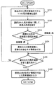
- FIG. 12 is a flowchart showing an example of processing progress of step S3 in the second embodiment.
- the direction estimation unit 221 selects one unselected local region from among the local regions indicating the staying crowd (that is, the local regions output by the staying crowd detection unit 21 in Step S2) (Step S31). ).
- the direction estimation unit 221 estimates the crowd direction in the local region image corresponding to the local region selected in step S31 (step S32).
- the direction estimation unit 221 estimates the direction of the crowd in such a manner that the reliability of the direction of the crowd can be determined by alternative. Since the specific example of estimating the direction of the crowd in the present embodiment has already been described, the description thereof is omitted here.
- the data adding unit 222 determines whether the reliability of the crowd direction estimated in Step S32 is high or low (Step S33). Since the specific example of the determination of the reliability of the direction of the crowd has already been described, the description thereof is omitted here.
- step S35 If the data adding unit 222 determines that the reliability is low, the process proceeds to step S35 without performing step S34.
- step S34 the data adding unit 222 adds information indicating the estimated crowd direction to the local region selected in step S31 (step S34). After step S34, the process proceeds to step S35.
- step S35 the direction estimating unit 221 determines whether or not all the local regions indicating the staying crowd (the local regions output by the staying crowd detecting unit 21 in step S2) have been selected (step S35). ).
- the crowd direction estimating unit 22 repeats the processing from step S31 onward.
- step S35 When all the local areas indicating the staying crowd have been selected (Yes in step S35), the data adding unit 222 adds each local area to which the information indicating the estimated direction of the crowd is added to the crowd type identifying unit 23. (Step S36). By executing step S36, step S3 (see FIG. 8) is completed.
- the same effect as in the first embodiment can be obtained. Further, in the second embodiment, the type of crowd identification process is performed only for the local area where the reliability of the estimated crowd orientation is high. Therefore, the accuracy of identifying the type of the crowd that has stayed can be improved.
- FIG. 13 is a block diagram illustrating a configuration example of a crowd type identification system according to the third embodiment of this invention.
- the data processing device 2 includes an upper crowd type identification unit 27 in addition to the staying crowd detection unit 21, the crowd direction estimation unit 22, and the crowd type identification unit 23. Prepare.
- the image acquisition device 1, the staying crowd detection unit 21, the crowd direction estimation unit 22, the crowd type identification unit 23, and the local region group storage unit 31 are those elements in the first embodiment or in the second embodiment. These are the same as those elements, and description thereof is omitted here. Further, the crowd process identification system in the third embodiment performs the same operation as that in steps S1 to S4 in the first embodiment or the same operation as that in steps S1 to S4 in the second embodiment. Execute.
- the kind and position of the crowd are determined for each combination of two local areas indicating the crowd that has stayed.
- the crowd location is the location of the two local regions used to identify the crowd type. It can be said that the crowd whose type and position are determined by the operations up to step S4 is a basic crowd.
- the crowd type identifying unit 23 outputs the crowd type and position (local region position) and the directions of the crowds of the two local regions corresponding to the crowd to the upper crowd type identifying unit 27. .
- the upper crowd type identification unit 27 identifies the upper crowd by performing clustering on the crowd based on the type and position of the crowd.
- the upper crowd is a set formed by gathering crowds. Thus, the upper crowd is more complicated than the crowd.
- the upper crowd type identifying unit 27 is based on the type of crowd belonging to the upper crowd, the arrangement pattern of each local area indicating the position of the crowd belonging to the upper crowd, and the pattern of the direction of the crowd in each local area. Identify the crowd type and output the top crowd type and location.
- the output mode of the type and position of the upper crowd is not particularly limited.
- the upper crowd type identifying unit 27 may display and output the type and position of each upper crowd, or may output in another manner.
- the type and position of each crowd obtained by the operations up to step S4 may be output together with the type and position of each upper crowd by the upper crowd type identifying unit 27. It can be said that the arrangement pattern of each local area indicating the position of the crowd belonging to the upper crowd is the arrangement pattern of each local area indicating the position of the upper crowd.
- the upper crowd type identifying unit 27 identifies clusters (lumps) having the crowd as an element by clustering the crowd. This cluster represents the upper crowd.
- the upper crowd type identifying unit 27 determines that the distance between different crowd positions (local area positions) is equal to or less than a predetermined threshold and the crowd types are common. Cluster the crowd by including them in the same cluster.
- a cluster obtained by clustering has a crowd as an element. Further, the individual crowd is accompanied by the position of the crowd (local area position) and the orientation of the local area crowd corresponding to the crowd.
- the upper crowd type identifying unit 27 determines the type of the upper crowd obtained by the clustering, the type of the crowd belonging to the upper crowd, the arrangement pattern of each local region indicating the position of the crowd belonging to the upper crowd, and each local Identify based on the pattern of crowd orientation in the area.
- the upper crowd type identifying unit 27 identifies the type of the upper crowd for each cluster (for each upper crowd) obtained by clustering.
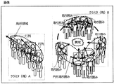
- FIG. 14 is an explanatory diagram showing an example of identifying the upper crowd.
- FIG. 14 shows an image.
- a crowd whose type is identified is surrounded by a dotted ellipse.
- the type of crowd is written near the ellipse.
- two local areas are included in one dotted-line ellipse.
- a rectangular local region is illustrated. Note that one local region may be included in a plurality of dotted ellipses.
- the number of crowds identified as “enclosed” is six.
- the upper crowd type identification unit 27 selects the crowd. Include in the same cluster.
- the positions of the six crowds described above are the distances between the positions of the crowds (local area positions) that are close to each other and close to the positions of the crowds identified as “surroundings” in the vicinity. Is less than or equal to a predetermined threshold.
- the types of these six crowds are common to “enclosure”.
- the upper crowd type identification unit 27 clusters the six crowds identified as “surround” into one cluster (lumb) (see cluster (lumb B) shown in FIG. 14). As a result, an upper crowd corresponding to the cluster (lumb) B is determined. Further, in FIG. 14, this upper crowd is represented by a broken-line circle.
- the type of crowd belonging to the upper crowd corresponding to cluster (lumb) B is “enclosed”.
- the arrangement pattern of each local area indicating the position of the crowd belonging to the upper crowd corresponding to the cluster (lumb) B is a circle.
- the pattern of the direction of the crowd in each local area is a pattern in which it faces the inside of a circle.
- the upper crowd type identification unit 27 identifies the type of the upper crowd corresponding to the cluster (lumb) B as “circular surrounding” based on the crowd type (“surrounding”), the arrangement pattern and the orientation pattern.
- the upper crowd type identification unit 27 includes a combination of a type of crowd belonging to the upper crowd, an arrangement pattern of each local area indicating the position of the crowd belonging to the upper crowd, and a pattern of the direction of the crowd in each local area, You may memorize
- the upper crowd type identifying unit 27 identifies “circular surrounding” as the upper crowd type is illustrated.
- the type of the upper crowd is not particularly limited.
- the upper crowd type identifying unit 27 may identify, for example, “straight line matrix”, “folding matrix”, and the like as the upper crowd type according to the crowd type, the arrangement pattern, and the orientation pattern.
- the upper crowd type identifying unit 27 may determine the position of each local area indicating the position of the crowd belonging to the upper crowd as the position of the upper crowd.
- the upper crowd type identification unit 27 is realized by a CPU of a computer that operates according to a crowd type identification program, for example.
- the upper crowd type identification unit 27 identifies the upper crowd based on the crowd type and position output from the crowd type identification unit 23. Furthermore, the upper crowd type identifying unit 27 is based on the type of crowd belonging to the upper crowd, the arrangement pattern of each local area indicating the position of the crowd belonging to the upper crowd, and the pattern of the direction of the crowd in each local area. Identify the top crowd types. Therefore, according to the present embodiment, the type of the upper crowd can be identified. Further, according to the present embodiment, since the type of the upper crowd is identified based on the type of the crowd, the arrangement pattern, and the orientation pattern, the conditions for corresponding to the individual types are restricted, and The type of crowd can be accurately identified.
- FIG. 15 is a block diagram showing a specific configuration example of the crowd type identification system according to the embodiment of the present invention.
- the crowd type identification system according to the embodiment of the present invention includes an image acquisition device 1, a storage device 3, and a computer 100.
- the storage device 3 includes a local region group storage unit 31.
- the computer 100 is connected to the image acquisition device 1 and the storage device 3.
- a computer readable medium 102 that stores a crowd type identification program 101 is also connected to the computer 100.
- the computer readable medium 102 is a storage device such as a magnetic disk or a semiconductor memory.
- the computer 100 includes a CPU 110, a memory 120, and an I / O (Input / Output) interface 130.
- the CPU 110, the memory 120, and the I / O interface 130 are communicably connected via, for example, a bus.
- the CPU 110 communicates via the I / O interface 130 with, for example, the image acquisition device 1, the storage device 3, an access device to the computer readable medium 102, and a device that receives the type and position of the crowd.
- the CPU 110 operates as the above-described CPU.
- the computer 100 reads the crowd type identification program 101 from the computer readable medium 102 at the time of startup, and operates as the data processing device 2 described in each embodiment according to the crowd type identification program 101. That is, the computer 100 operates as the staying crowd detection unit 21, the crowd direction estimation unit 22, and the crowd type identification unit 23 in the first embodiment according to the crowd type identification program 101. In addition, the computer 100 may operate as the detection unit 24 and the crowd type identification unit 23 in the modified example of the first embodiment (see FIG. 11) according to the crowd type identification program 101.
- the computer 100 may operate as the staying crowd detection unit 21, the crowd direction estimation unit 22, and the crowd type identification unit 23 in the second embodiment according to the crowd type identification program 101. Further, the computer 100 may operate as the staying crowd detection unit 21, the crowd direction estimation unit 22, the crowd type identification unit 23, and the upper crowd type identification unit 27 in the third embodiment according to the crowd type identification program 101.
- the computer 100 may operate as a data processing apparatus according to fourth and fifth embodiments described later according to the crowd type identification program 101.
- the CPU 110 of the computer 100 may read the crowd type identification program 101 from the computer readable medium 102 and load the read crowd type identification program into the memory 120, for example.
- CPU 110 may execute a crowd type identification program loaded in memory 120.
- CPU110 should just operate
- FIG. 1
- the data processing apparatus may be realized by dedicated hardware such as a circuit.
- the data processing apparatus according to each embodiment of the present invention is a combination of a computer 100 including a memory 120 loaded with a crowd type identification program and a CPU 110 that executes the crowd type identification program, and dedicated hardware such as a circuit. It may be realized.
- the staying crowd detection unit 21, the crowd direction estimation unit 22, and the crowd type identification unit 23 in the first embodiment may be realized by the CPU 110 that executes the crowd type identification program 101 loaded in the memory 120.
- the staying crowd detection unit 21, the crowd direction estimation unit 22, and the crowd type identification unit 23 in the first embodiment may be realized by dedicated hardware such as a circuit.
- the staying crowd detection unit 21, the crowd direction estimation unit 22, and the crowd type identification unit 23 in the first embodiment may be realized by a combination of the CPU 110 and a dedicated circuit.
- the detection unit 24 and the crowd type identification unit 23 in the modification of the first embodiment may be realized by the CPU 110 that executes the crowd type identification program 101 loaded in the memory 120.
- the detection unit 24 and the crowd type identification unit 23 in the modification of the first embodiment may be realized by dedicated hardware such as a circuit.
- the detection unit 24 and the crowd type identification unit 23 in the modification of the first embodiment may be realized by a combination of the CPU 110 and a dedicated circuit.
- the staying crowd detection unit 21, the crowd direction estimation unit 22, and the crowd type identification unit 23 in the second embodiment may be realized by the CPU 110 that executes the crowd type identification program 101 loaded in the memory 120.
- the staying crowd detection unit 21, the crowd direction estimation unit 22, and the crowd type identification unit 23 in the second embodiment may be realized by dedicated hardware such as a circuit.
- the staying crowd detection unit 21, the crowd direction estimation unit 22, and the crowd type identification unit 23 in the second embodiment may be realized by a combination of the CPU 110 and a dedicated circuit.
- the staying crowd detection unit 21, the crowd direction estimation unit 22, the crowd type identification unit 23, and the upper crowd type identification unit 27 in the third embodiment are realized by the CPU 110 that executes the crowd type identification program 101 loaded in the memory 120. It may be.
- the staying crowd detection unit 21, the crowd direction estimation unit 22, the crowd type identification unit 23, and the upper crowd type identification unit 27 in the third embodiment may be realized by dedicated hardware such as a circuit.
- the staying crowd detection unit 21, the crowd direction estimation unit 22, the crowd type identification unit 23, and the upper crowd type identification unit 27 in the third embodiment may be realized by a combination of the CPU 110 and a dedicated circuit.
- the staying crowd detection unit 21, the crowd direction estimation unit 22, and the crowd type identification unit 23 in the fourth embodiment may be realized by a CPU 110 that executes a crowd type identification program 101 loaded in the memory 120. .
- the staying crowd detection unit 21, the crowd direction estimation unit 22, and the crowd type identification unit 23 in the fourth embodiment may be realized by dedicated hardware such as a circuit.
- the staying crowd detection unit 21, the crowd direction estimation unit 22, and the crowd type identification unit 23 in the fourth embodiment may be realized by a combination of the CPU 110 and a dedicated circuit.
- the detection unit 71 and the identification unit 72 in the fifth embodiment may be realized by the CPU 110 that executes the crowd type identification program 101 loaded in the memory 120.
- the detection unit 71 and the identification unit 72 in the fifth embodiment may be realized by dedicated hardware such as a circuit.
- the detection unit 71 and the identification unit 72 in the fifth embodiment may be realized by a combination of the CPU 110 and a dedicated circuit.
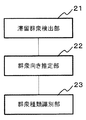
- FIG. 16 is a block diagram illustrating an example of the configuration of the crowd type identification system according to the present embodiment.
- the crowd type identification system according to the present embodiment includes a staying crowd detection unit 21, a crowd direction estimation unit 22, and a crowd type identification unit 23.
- the crowd type identification system of the present embodiment may be realized by a single device (for example, a data processing device including a staying crowd detection unit 21, a crowd orientation estimation unit 22, and a crowd type identification unit 23).
- the crowd type identification system of the present embodiment may be realized by a plurality of devices connected to be communicable with each other.
- the staying crowd detection unit 21 detects a local area indicating a staying crowd from local areas defined in an image acquired by an image acquisition device (for example, the above-described image acquisition device 1).
- the crowd direction estimation unit 22 estimates the direction of the crowd for an image of a portion corresponding to the local region detected by the staying crowd detection unit 21 (for example, the above-described local region image), and determines the direction of the crowd. Append to local area.
- the crowd type identifying unit 23 determines a relative vector indicating the relative positional relationship between the two local regions and the crowd direction of the two local regions for the local region to which the crowd direction is added by the crowd direction estimating unit 22. Used to identify the type of crowd composed of a plurality of people who have stayed and to output the type and location of the crowd.
- Such a configuration makes it possible to identify various types of crowded crowds appearing in the image.
- FIG. 17 is a block diagram illustrating an example of the configuration of the crowd type identification system according to the present embodiment.
- the crowd type identification system according to this embodiment includes a detection unit 71 and an identification unit 72.
- the crowd type identification system of the present embodiment may be realized by a single device (for example, a data processing device including the detection unit 71 and the identification unit 72).
- the crowd type identification system of the present embodiment may be realized by a plurality of devices connected to be communicable with each other.
- the detection unit 71 detects a plurality of partial regions (for example, the above-described local region) including the staying crowd from the image.
- the identifying unit 72 (for example, the crowd type identifying unit 23) analyzes the first partial region and the second partial region, and identifies the crowd type of the first partial region and the second partial region.
- Such a configuration makes it possible to identify various types of crowded crowds appearing in the image.
- an estimation unit for example, the above-described crowd direction estimation unit 22 that estimates the direction of the crowd of each of the first partial region and the second partial region is provided, and the identification unit 72 performs a second operation with respect to the first partial region.
- a calculation unit for example, the above-described relative vector calculation unit 231 that calculates the orientation (for example, the above-described relative vector) of the second partial region, the direction of the crowd of the first partial region, and the crowd of the second partial region
- an analysis unit that identifies the type of crowd of the first partial area and the second partial area (for example, the analysis unit 232 described above) The structure containing these may be sufficient.
- a staying crowd detection means for detecting a local area indicating a staying crowd from local areas defined in an image acquired by the image acquisition device; Targeting the image of the portion corresponding to the local area detected by the staying crowd detection means, estimating the direction of the crowd, crowd direction estimation means for adding the direction of the crowd to the local area; For the local region to which the crowd direction is added by the crowd direction estimation means, a plurality of the plurality of remaining regions are obtained using a relative vector indicating a relative positional relationship between the two local regions and the crowd direction of the two local regions.
- a crowd type identifying system comprising: a crowd type identifying means for identifying a crowd type composed of persons and outputting the crowd type and position.
- the staying crowd detection means estimates the degree of staying of the object indicating the staying state of the object and the number of people in the local area indicating the density of the crowd for the image of the portion corresponding to the local area, and the staying of the object
- the crowd type identification system according to Supplementary Note 1 or Supplementary Note 2, wherein a local region indicating a crowd that has stayed is detected based on the degree and the number of persons.
- the crowd direction estimation means does not add the crowd direction to a local region corresponding to the crowd direction when the crowd direction is low when the crowd direction reliability is low.
- the crowd type identification system according to any one of the above.
- the upper crowd is obtained using the crowd type and position output to the crowd type identification means, the type of crowd belonging to the upper crowd, the arrangement pattern of each local region indicating the position of the upper crowd, and the respective Any one of the appendix 1 to the appendix 4, further comprising upper crowd type identifying means for identifying the type of the upper crowd based on the pattern of the direction of the crowd in the local area and outputting the type and position of the upper crowd.
- the upper crowd type identification means obtains an upper crowd by clustering the crowd using the crowd type and position, and identifies the upper crowd type for each cluster obtained by clustering. Identification system.
- a crowd type identification system comprising: identification means for analyzing the first partial region and the second partial region and identifying the crowd type of the first partial region and the second partial region.
- the identification means includes Calculating means for calculating an orientation of the second partial area with respect to the first partial area; Based on the crowd orientation of the first partial region, the crowd orientation of the second partial region, and the orientation of the second partial region relative to the first partial region, the first partial region.
- the crowd type identification system according to claim 9, further comprising: analysis means for identifying a crowd type of the second partial area.
- Appendix 18 18. The method of identifying a crowd type according to any one of appendix 11 to appendix 17, wherein the result of local region-based learning is applied to crowd direction estimation.
- a method of identifying a crowd type comprising: analyzing a first partial region and a second partial region to identify a crowd type of the first partial region and the second partial region.
- a staying crowd detection process for detecting a local area indicating a staying crowd from local areas defined in an image acquired by the image acquisition device, Targeting an image of a portion corresponding to the local area detected by the staying crowd detection process, estimating the direction of the crowd, adding the crowd direction to the local area, and a crowd direction estimation process, and the crowd direction Concerning the local region to which the orientation of the crowd is added in the estimation process, a relative vector indicating the relative positional relationship between the two local regions and the crowd direction of the two local regions are configured by a plurality of people who have stayed.
- a crowd type identification program for executing a crowd type identification process for identifying a crowd type and outputting the crowd type and position.
- appendix 22 In the computer, The storage medium according to appendix 21, which stores the crowd type identification program for identifying the crowd type using two local areas whose relative vectors are equal to or smaller than a predetermined size in the crowd type identification process. .
- Appendix 24 In the computer, When estimating the direction of the crowd in the crowd direction estimation process, if the reliability of the direction of the crowd is low, the direction of the crowd is not added to the local area corresponding to the direction of the crowd. 24.
- the storage medium according to any one of appendix 21 to appendix 23 for storing.
- the upper crowd is obtained using the crowd type and position output in the crowd type identification process, the type of crowd belonging to the upper crowd, the arrangement pattern of each local region indicating the position of the upper crowd, and the respective Supplementary note 21 for storing the crowd type identification program for identifying the type of the upper crowd based on the pattern of the direction of the crowd in the local region and executing the upper crowd type identification process for outputting the type and position of the upper crowd 25.
- the storage medium according to any one of items 1 to 24.
- appendix 27 In the computer, 24.
- Appendix 28 In the computer, 28.
- the storage medium according to any one of appendix 21 to appendix 27, wherein the crowd type identification program stores the crowd type identification program for applying a result of local area-based learning to crowd orientation estimation in the crowd orientation estimation process.
- (Appendix 30) In the computer, Executing an estimation process for estimating a direction of a crowd of each of the first partial area and the second partial area; In the identification process, A calculation process for calculating an orientation of the second partial area with respect to the first partial area; a direction of the crowd of the first partial area; a direction of the crowd of the second partial area; And storing the crowd type identification program for executing an analysis process for identifying a crowd type of the first partial area and the second partial area based on an orientation of the second partial area with respect to a partial area of the second partial area.
- the present invention is preferably applied to a crowd type identification system that identifies the type of crowd shown in an image. Further, the present invention can be used for, for example, suspicious person recognition, suspicious object leaving recognition, abnormal state recognition, abnormal action recognition, etc. in the monitoring field that requires the identification of the type of crowd. In addition, the present invention can be used for, for example, behavior analysis in the marketing field, analysis of environmental conditions, and the like. The present invention can also be applied to an application as an input interface for sending the type and position of the crowd to other devices. Further, the present invention can also be applied to a video / video search device using the type and position of the crowd as a trigger key.
Landscapes
- Engineering & Computer Science (AREA)
- Theoretical Computer Science (AREA)
- Physics & Mathematics (AREA)
- General Physics & Mathematics (AREA)
- Computer Vision & Pattern Recognition (AREA)
- Data Mining & Analysis (AREA)
- Multimedia (AREA)
- Artificial Intelligence (AREA)
- Life Sciences & Earth Sciences (AREA)
- Bioinformatics & Cheminformatics (AREA)
- Bioinformatics & Computational Biology (AREA)
- Evolutionary Biology (AREA)
- Evolutionary Computation (AREA)
- General Engineering & Computer Science (AREA)
- Geometry (AREA)
- Image Analysis (AREA)
- Alarm Systems (AREA)
Abstract
La présente invention a pour but de fournir un système d'identification de type de foule qui rende possible l'identification de divers types en tant que types de foules accumulées, montrées sur une image. Un moyen de détection de foule accumulée (21) détecte une région locale indiquant une foule accumulée parmi des régions locales, établies dans une image acquise par un dispositif d'acquisition d'image. Un moyen d'estimation d'orientation de foule (22) estime l'orientation d'une foule en utilisant, comme objet, une image partielle qui correspond à la région locale détectée par le moyen de détection de foule accumulée (21) et ajoute l'orientation de la foule à la région locale. Pour la région locale à laquelle l'orientation de la foule a été ajoutée par le moyen d'estimation d'orientation de foule (22), un moyen d'identification de type de foule (23) utilise un vecteur relatif indiquant la relation de position relative de deux régions locales et l'orientation des foules dans les deux régions locales afin d'identifier le type de foules configurées par une pluralité de personnes accumulées et transmet le type et la position des foules.
Priority Applications (8)
| Application Number | Priority Date | Filing Date | Title |
|---|---|---|---|
| US16/082,763 US10789484B2 (en) | 2016-03-07 | 2017-02-28 | Crowd type classification system, crowd type classification method and storage medium for storing crowd type classification program |
| JP2018504388A JP6988790B2 (ja) | 2016-03-07 | 2017-02-28 | 群衆種類識別システム、群衆種類識別方法および群衆種類識別プログラム |
| US16/512,490 US10885350B2 (en) | 2016-03-07 | 2019-07-16 | Crowd type classification system, crowd type classification method and storage medium for storing crowd type classification program |
| US16/512,496 US10891493B2 (en) | 2016-03-07 | 2019-07-16 | Crowd type classification system, crowd type classification method and storage medium for storing crowd type classification program |
| US17/125,326 US11727578B2 (en) | 2016-03-07 | 2020-12-17 | Crowd type classification system, crowd type classification method and storage medium for storing crowd type classification program |
| US18/344,542 US12175683B2 (en) | 2016-03-07 | 2023-06-29 | Crowd type classification system, crowd type classification method and storage medium for storing crowd type classification program |
| US18/938,464 US20250061589A1 (en) | 2016-03-07 | 2024-11-06 | Crowd type classification system, crowd type classification method and storage medium for storing crowd type classification program |
| US18/938,604 US20250069236A1 (en) | 2016-03-07 | 2024-11-06 | Crowd type classification system, crowd type classification method and storage medium for storing crowd type classification program |
Applications Claiming Priority (2)
| Application Number | Priority Date | Filing Date | Title |
|---|---|---|---|
| JP2016043157 | 2016-03-07 | ||
| JP2016-043157 | 2016-03-07 |
Related Child Applications (4)
| Application Number | Title | Priority Date | Filing Date |
|---|---|---|---|
| US16/082,736 A-371-Of-International US11045360B2 (en) | 2016-03-30 | 2017-02-24 | Underpants-type disposable diaper |
| US16/082,763 A-371-Of-International US10789484B2 (en) | 2016-03-07 | 2017-02-28 | Crowd type classification system, crowd type classification method and storage medium for storing crowd type classification program |
| US16/512,490 Continuation US10885350B2 (en) | 2016-03-07 | 2019-07-16 | Crowd type classification system, crowd type classification method and storage medium for storing crowd type classification program |
| US16/512,496 Continuation US10891493B2 (en) | 2016-03-07 | 2019-07-16 | Crowd type classification system, crowd type classification method and storage medium for storing crowd type classification program |
Publications (1)
| Publication Number | Publication Date |
|---|---|
| WO2017154655A1 true WO2017154655A1 (fr) | 2017-09-14 |
Family
ID=59790289
Family Applications (1)
| Application Number | Title | Priority Date | Filing Date |
|---|---|---|---|
| PCT/JP2017/007643 Ceased WO2017154655A1 (fr) | 2016-03-07 | 2017-02-28 | Système d'identification de type de foule, procédé d'identification de type de foule et support de stockage permettant de stocker un programme d'identification de type de foule |
Country Status (3)
| Country | Link |
|---|---|
| US (7) | US10789484B2 (fr) |
| JP (1) | JP6988790B2 (fr) |
| WO (1) | WO2017154655A1 (fr) |
Cited By (5)
| Publication number | Priority date | Publication date | Assignee | Title |
|---|---|---|---|---|
| JP2020074055A (ja) * | 2018-03-05 | 2020-05-14 | 日本テレビ放送網株式会社 | 画像識別装置、分類システム、制作支援システム、それらの方法及びプログラム |
| WO2020105146A1 (fr) * | 2018-11-21 | 2020-05-28 | 日本電気株式会社 | Dispositif de traitement d'informations, procédé de commande, et programme |
| CN111353513A (zh) * | 2018-12-20 | 2020-06-30 | 杭州海康威视数字技术股份有限公司 | 一种目标人群筛选的方法、装置、终端和存储介质 |
| JPWO2021176997A1 (fr) * | 2020-03-06 | 2021-09-10 | ||
| JP2024029946A (ja) * | 2022-08-23 | 2024-03-07 | 日本電気株式会社 | 画像処理装置、画像処理方法、およびプログラム |
Families Citing this family (3)
| Publication number | Priority date | Publication date | Assignee | Title |
|---|---|---|---|---|
| US10789484B2 (en) * | 2016-03-07 | 2020-09-29 | Nec Corporation | Crowd type classification system, crowd type classification method and storage medium for storing crowd type classification program |
| SG10201802673VA (en) * | 2018-03-29 | 2019-10-30 | Nec Asia Pacific Pte Ltd | Method and system for integration and automatic switching of crowd estimation techniques |
| CN116129361B (zh) * | 2023-03-24 | 2023-08-08 | 武汉中科通达高新技术股份有限公司 | 一种基于距离度量的人群聚集识别方法及装置 |
Citations (3)
| Publication number | Priority date | Publication date | Assignee | Title |
|---|---|---|---|---|
| WO2005039181A1 (fr) * | 2003-10-21 | 2005-04-28 | Matsushita Electric Industrial Co., Ltd. | Dispositif de surveillance |
| JP2011248548A (ja) * | 2010-05-25 | 2011-12-08 | Fujitsu Ltd | コンテンツ決定プログラムおよびコンテンツ決定装置 |
| WO2014207991A1 (fr) * | 2013-06-28 | 2014-12-31 | 日本電気株式会社 | Dispositif, procédé et programme de génération de données d'apprentissage, et dispositif, procédé et programme de reconnaissance d'état de foule |
Family Cites Families (14)
| Publication number | Priority date | Publication date | Assignee | Title |
|---|---|---|---|---|
| JP2007265290A (ja) | 2006-03-29 | 2007-10-11 | Oki Electric Ind Co Ltd | 待ち行列情報通知システム |
| JP2011248836A (ja) | 2010-05-31 | 2011-12-08 | Nomura Research Institute Ltd | 滞留検出システム及びプログラム |
| JP6358258B2 (ja) | 2013-09-19 | 2018-07-18 | 日本電気株式会社 | 画像処理システム、画像処理方法及びプログラム |
| JP5613815B1 (ja) * | 2013-10-29 | 2014-10-29 | パナソニック株式会社 | 滞留状況分析装置、滞留状況分析システムおよび滞留状況分析方法 |
| US11138443B2 (en) * | 2014-06-30 | 2021-10-05 | Nec Corporation | Guidance processing apparatus and guidance method |
| JP6597611B2 (ja) * | 2014-07-25 | 2019-10-30 | 日本電気株式会社 | 画像処理装置、監視システム、画像処理方法、及びプログラム |
| WO2016114134A1 (fr) * | 2015-01-14 | 2016-07-21 | 日本電気株式会社 | Dispositif d'estimation de condition de mouvement, procédé d'estimation de condition de mouvement et support d'enregistrement de programme |
| EP3311364B1 (fr) * | 2015-09-30 | 2018-12-26 | FotoNation Limited | Procédé et système de suivi d'un objet |
| US10789484B2 (en) * | 2016-03-07 | 2020-09-29 | Nec Corporation | Crowd type classification system, crowd type classification method and storage medium for storing crowd type classification program |
| US10856387B2 (en) * | 2016-08-23 | 2020-12-01 | Signify Holding B.V. | Crowd entertainment |
| JP6904677B2 (ja) * | 2016-08-30 | 2021-07-21 | キヤノン株式会社 | 情報処理装置、情報処理方法及びプログラム |
| WO2018061976A1 (fr) * | 2016-09-28 | 2018-04-05 | 株式会社日立国際電気 | Dispositif de traitement d'images |
| US10762653B2 (en) * | 2016-12-27 | 2020-09-01 | Canon Kabushiki Kaisha | Generation apparatus of virtual viewpoint image, generation method, and storage medium |
| US10691956B2 (en) * | 2017-05-12 | 2020-06-23 | Canon Kabushiki Kaisha | Information processing apparatus, information processing system, information processing method, and storage medium having determination areas corresponding to waiting line |
-
2017
- 2017-02-28 US US16/082,763 patent/US10789484B2/en active Active
- 2017-02-28 JP JP2018504388A patent/JP6988790B2/ja active Active
- 2017-02-28 WO PCT/JP2017/007643 patent/WO2017154655A1/fr not_active Ceased
-
2019
- 2019-07-16 US US16/512,490 patent/US10885350B2/en active Active
- 2019-07-16 US US16/512,496 patent/US10891493B2/en active Active
-
2020
- 2020-12-17 US US17/125,326 patent/US11727578B2/en active Active
-
2023
- 2023-06-29 US US18/344,542 patent/US12175683B2/en active Active
-
2024
- 2024-11-06 US US18/938,604 patent/US20250069236A1/en active Pending
- 2024-11-06 US US18/938,464 patent/US20250061589A1/en active Pending
Patent Citations (3)
| Publication number | Priority date | Publication date | Assignee | Title |
|---|---|---|---|---|
| WO2005039181A1 (fr) * | 2003-10-21 | 2005-04-28 | Matsushita Electric Industrial Co., Ltd. | Dispositif de surveillance |
| JP2011248548A (ja) * | 2010-05-25 | 2011-12-08 | Fujitsu Ltd | コンテンツ決定プログラムおよびコンテンツ決定装置 |
| WO2014207991A1 (fr) * | 2013-06-28 | 2014-12-31 | 日本電気株式会社 | Dispositif, procédé et programme de génération de données d'apprentissage, et dispositif, procédé et programme de reconnaissance d'état de foule |
Non-Patent Citations (1)
| Title |
|---|
| MASAHIRO KUNIMOTO ET AL.: "A Study on Automating Cinematographic Virtual Camera in Computer Animation", DAI 52 KAI (HEISEI 8 NEN ZENKI) ZENKOKU TAIKAI KOEN RONBUNSHU (2) JINKO CHINO OYOBI NINCHI KAGAKU MEDIA JOHO SHORI, 6 March 1996 (1996-03-06), pages 2-357 - 2-258 * |
Cited By (12)
| Publication number | Priority date | Publication date | Assignee | Title |
|---|---|---|---|---|
| JP2020074055A (ja) * | 2018-03-05 | 2020-05-14 | 日本テレビ放送網株式会社 | 画像識別装置、分類システム、制作支援システム、それらの方法及びプログラム |
| JP7122243B2 (ja) | 2018-03-05 | 2022-08-19 | 日本テレビ放送網株式会社 | 画像識別装置、分類システム、制作支援システム、それらの方法及びプログラム |
| WO2020105146A1 (fr) * | 2018-11-21 | 2020-05-28 | 日本電気株式会社 | Dispositif de traitement d'informations, procédé de commande, et programme |
| JPWO2020105146A1 (ja) * | 2018-11-21 | 2021-10-07 | 日本電気株式会社 | 情報処理装置、制御方法、及びプログラム |
| JP7211428B2 (ja) | 2018-11-21 | 2023-01-24 | 日本電気株式会社 | 情報処理装置、制御方法、及びプログラム |
| US12014563B2 (en) | 2018-11-21 | 2024-06-18 | Nec Corporation | Information processing apparatus, control method, and non-transitory storage medium |
| US12154364B2 (en) | 2018-11-21 | 2024-11-26 | Nec Corporation | Information processing apparatus, control method, and non-transitory storage medium |
| US12154365B2 (en) | 2018-11-21 | 2024-11-26 | Nec Corporation | Information processing apparatus, control method, and non-transitory storage medium |
| CN111353513A (zh) * | 2018-12-20 | 2020-06-30 | 杭州海康威视数字技术股份有限公司 | 一种目标人群筛选的方法、装置、终端和存储介质 |
| CN111353513B (zh) * | 2018-12-20 | 2023-04-18 | 杭州海康威视数字技术股份有限公司 | 一种目标人群筛选的方法、装置、终端和存储介质 |
| JPWO2021176997A1 (fr) * | 2020-03-06 | 2021-09-10 | ||
| JP2024029946A (ja) * | 2022-08-23 | 2024-03-07 | 日本電気株式会社 | 画像処理装置、画像処理方法、およびプログラム |
Also Published As
| Publication number | Publication date |
|---|---|
| US11727578B2 (en) | 2023-08-15 |
| US20190340443A1 (en) | 2019-11-07 |
| JP6988790B2 (ja) | 2022-01-05 |
| US20210103739A1 (en) | 2021-04-08 |
| US10789484B2 (en) | 2020-09-29 |
| JPWO2017154655A1 (ja) | 2019-01-10 |
| US10885350B2 (en) | 2021-01-05 |
| US20190102629A1 (en) | 2019-04-04 |
| US12175683B2 (en) | 2024-12-24 |
| US20190340444A1 (en) | 2019-11-07 |
| US20250061589A1 (en) | 2025-02-20 |
| US20250069236A1 (en) | 2025-02-27 |
| US20230351617A1 (en) | 2023-11-02 |
| US10891493B2 (en) | 2021-01-12 |
Similar Documents
| Publication | Publication Date | Title |
|---|---|---|
| JP6988790B2 (ja) | 群衆種類識別システム、群衆種類識別方法および群衆種類識別プログラム | |
| KR102261061B1 (ko) | 컨볼루션 신경망을 이용하여 poi 변화를 검출하기 위한 시스템 및 방법 | |
| US9824459B2 (en) | Tracking objects between images | |
| JP6950692B2 (ja) | 人流推定装置、人流推定方法およびプログラム | |
| JP6032921B2 (ja) | 物体検出装置及びその方法、プログラム | |
| JP6814673B2 (ja) | 移動経路予測装置、及び移動経路予測方法 | |
| KR20250088698A (ko) | 실내 측위 및 추적을 위한 심층 스마트폰 센서 융합 | |
| JP6618395B2 (ja) | 行動価値によって調査対象の位置を予測する装置、プログラム及び方法 | |
| CN108470353A (zh) | 一种目标跟踪方法、装置和存储介质 | |
| JP5936561B2 (ja) | 画像における外観及びコンテキストに基づく物体分類 | |
| US11922667B2 (en) | Object region identification device, object region identification method, and object region identification program | |
| US12293586B2 (en) | Computer-readable recording medium storing person identification determination program, person identification determination method, and information processing apparatus | |
| CN116745808B (zh) | 作业估计装置、作业估计方法和计算机可读取的记录介质 | |
| TWI780563B (zh) | 圖像定位模型獲取方法、終端和電腦可讀儲存介質 | |
| US9299000B2 (en) | Object region extraction system, method and program | |
| CN114202804A (zh) | 行为动作识别方法、装置、处理设备及存储介质 | |
| CN107665495B (zh) | 对象跟踪方法及对象跟踪装置 | |
| CN117292435A (zh) | 动作识别方法、装置及计算机设备 | |
| Mosca et al. | Human Walking Behavior detection with a RGB-D Sensors Network for Ambient Assisted Living Applications. | |
| Jeganathan et al. | RETRACTED: Computer vision based human fall detection and classification for real-time videos | |
| Majid et al. | Harmonizing space–time dynamics for precision in human action recognition | |
| Marouane et al. | Enabling pedometers on basis of visual feature point conversion | |
| WO2024247039A1 (fr) | Dispositif de traitement d'informations, procédé de traitement d'informations et support d'enregistrement | |
| Menegatti et al. | Robot localisation enhanced by a distributed vision system in dynamic environments | |
| WO2024084601A1 (fr) | Procédé de détection de changement, système de détection de changement et appareil de détection de changement |
Legal Events
| Date | Code | Title | Description |
|---|---|---|---|
| WWE | Wipo information: entry into national phase |
Ref document number: 2018504388 Country of ref document: JP |
|
| NENP | Non-entry into the national phase |
Ref country code: DE |
|
| 121 | Ep: the epo has been informed by wipo that ep was designated in this application |
Ref document number: 17762995 Country of ref document: EP Kind code of ref document: A1 |
|
| 122 | Ep: pct application non-entry in european phase |
Ref document number: 17762995 Country of ref document: EP Kind code of ref document: A1 |