WO2017154826A1 - Support, module photovoltaïque et système photovoltaïque - Google Patents
Support, module photovoltaïque et système photovoltaïque Download PDFInfo
- Publication number
- WO2017154826A1 WO2017154826A1 PCT/JP2017/008740 JP2017008740W WO2017154826A1 WO 2017154826 A1 WO2017154826 A1 WO 2017154826A1 JP 2017008740 W JP2017008740 W JP 2017008740W WO 2017154826 A1 WO2017154826 A1 WO 2017154826A1
- Authority
- WO
- WIPO (PCT)
- Prior art keywords
- solar cell
- cell panel
- contact member
- contact
- panel
- Prior art date
- Legal status (The legal status is an assumption and is not a legal conclusion. Google has not performed a legal analysis and makes no representation as to the accuracy of the status listed.)
- Ceased
Links
Images



Classifications
-
- H—ELECTRICITY
- H02—GENERATION; CONVERSION OR DISTRIBUTION OF ELECTRIC POWER
- H02S—GENERATION OF ELECTRIC POWER BY CONVERSION OF INFRARED RADIATION, VISIBLE LIGHT OR ULTRAVIOLET LIGHT, e.g. USING PHOTOVOLTAIC [PV] MODULES
- H02S20/00—Supporting structures for PV modules
- H02S20/20—Supporting structures directly fixed to an immovable object
- H02S20/22—Supporting structures directly fixed to an immovable object specially adapted for buildings
- H02S20/23—Supporting structures directly fixed to an immovable object specially adapted for buildings specially adapted for roof structures
-
- Y—GENERAL TAGGING OF NEW TECHNOLOGICAL DEVELOPMENTS; GENERAL TAGGING OF CROSS-SECTIONAL TECHNOLOGIES SPANNING OVER SEVERAL SECTIONS OF THE IPC; TECHNICAL SUBJECTS COVERED BY FORMER USPC CROSS-REFERENCE ART COLLECTIONS [XRACs] AND DIGESTS
- Y02—TECHNOLOGIES OR APPLICATIONS FOR MITIGATION OR ADAPTATION AGAINST CLIMATE CHANGE
- Y02B—CLIMATE CHANGE MITIGATION TECHNOLOGIES RELATED TO BUILDINGS, e.g. HOUSING, HOUSE APPLIANCES OR RELATED END-USER APPLICATIONS
- Y02B10/00—Integration of renewable energy sources in buildings
- Y02B10/10—Photovoltaic [PV]
-
- Y—GENERAL TAGGING OF NEW TECHNOLOGICAL DEVELOPMENTS; GENERAL TAGGING OF CROSS-SECTIONAL TECHNOLOGIES SPANNING OVER SEVERAL SECTIONS OF THE IPC; TECHNICAL SUBJECTS COVERED BY FORMER USPC CROSS-REFERENCE ART COLLECTIONS [XRACs] AND DIGESTS
- Y02—TECHNOLOGIES OR APPLICATIONS FOR MITIGATION OR ADAPTATION AGAINST CLIMATE CHANGE
- Y02E—REDUCTION OF GREENHOUSE GAS [GHG] EMISSIONS, RELATED TO ENERGY GENERATION, TRANSMISSION OR DISTRIBUTION
- Y02E10/00—Energy generation through renewable energy sources
- Y02E10/50—Photovoltaic [PV] energy
Definitions
- the present invention relates to a gantry, a solar cell module, a solar cell system, and more particularly to a gantry, a solar cell module, and a solar cell system including a solar cell panel.
- a frame is arranged on each side of the solar cell module, and the frame is installed on a roof base plate or the like.
- a snow load may act from the surface side of the solar cell module toward the back surface, and the solar cell module may be damaged.
- the center part on the back surface side of the solar cell module is supported by an elastic member that is compressible and deformable provided between the solar cell module and the roof (see, for example, Patent Document 1).
- Elasticity of an elastic body generally deteriorates with time. Furthermore, since the place where the solar cell module is installed is likely to become high temperature due to the influence of direct sunlight, the elasticity of the elastic body is likely to further deteriorate. When the deteriorated elastic body is periodically replaced, it cannot be said that damage due to bending of the solar cell panel is easily prevented. Therefore, it is required to easily prevent damage due to the bending of the solar cell panel.
- the present invention has been made in view of such circumstances, and an object thereof is to provide a technique for easily preventing damage caused by bending of a solar cell panel.
- a frame according to an aspect of the present invention is a frame for installing a solar cell module in which a frame is arranged on a peripheral portion of a solar cell panel including an upper surface and a lower surface facing opposite to each other.
- the solar cell module includes a plurality of fixing portions that fix each of the opposed frames, and a contact member that is disposed between the plurality of fixing portions. In the direction from the lower surface to the upper surface of the solar cell panel, the thickness of the contact member is smaller than the distance from at least one of the plurality of fixing portions to the lower surface of the solar cell panel.
- This solar cell module includes a solar cell panel including an upper surface and a lower surface facing in opposite directions, a frame disposed on a peripheral edge of the solar cell panel, and a contact member attached to the lower surface of the solar cell panel. In the direction from the lower surface to the upper surface of the solar cell panel, the thickness of the contact member is smaller than the distance from the lower end of the frame to the lower surface of the solar cell panel.
- the solar cell system includes a solar cell module in which a frame is disposed on a peripheral portion of a solar cell panel including an upper surface and a lower surface facing opposite to each other, and a plurality of fixing portions that fix each of the opposed frames in the solar cell module. And a gantry including.
- the gantry includes a contact member disposed between the plurality of fixing portions. In the direction from the lower surface to the upper surface of the solar cell panel, the thickness of the contact member is smaller than the distance from at least one of the plurality of fixing portions to the lower surface of the solar cell panel.
- Still another embodiment of the present invention is also a solar cell system.
- the solar cell system includes a solar cell module in which a frame is disposed on a peripheral portion of a solar cell panel including an upper surface and a lower surface facing opposite to each other, and a plurality of fixing portions that fix each of the opposed frames in the solar cell module. And a gantry including.
- the solar cell module further includes a contact member attached to the lower surface of the solar cell panel. In the direction from the lower surface to the upper surface of the solar cell panel, the thickness of the contact member is smaller than the distance from at least one of the plurality of fixing portions to the lower surface of the solar cell panel.
- FIGS. 5A and 5B are cross-sectional views showing the configuration of the solar cell system of FIG. It is a top view which shows the structure of the solar cell module of FIG. It is a top view which shows another structure of the solar cell module of FIG.
- FIGS. 8A and 8B are cross-sectional views showing still another configuration of the solar cell module of FIG. It is a top view which shows the structure of the solar cell module of FIG. It is a top view which shows another structure of the solar cell module of FIG.
- Example 1 of this invention is related with the mount for installing a solar cell module.
- a plurality of mounts extending from the roof ridge toward the eave are arranged side by side on the roof, and the solar cell module is installed on the mount.
- a frame is arranged at the peripheral edge of the solar cell panel in the solar cell module, and the frame is fixed to the gantry.
- the solar cell panel bends in the direction of the roof, the solar cell panel may be damaged due to the solar cell panel coming into contact with the mount.
- the gantry according to the present embodiment is configured as follows.
- the solar cell panel includes a portion having relatively high resistance to contact and a portion having low resistance.
- An example of a portion having relatively low resistance to contact is an inter-cell wiring material for connecting a plurality of solar cells in a solar cell panel.
- portions other than the inter-cell wiring member in the solar cell panel have a relatively high resistance to contact. Then, when a solar cell panel bends, the member for contact is arrange
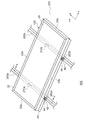
- FIG. 1 is a perspective view showing a configuration of a solar cell system 500 according to Embodiment 1 of the present invention.
- a gantry 200 collectively called a first gantry 200 a and a second gantry 200 b is disposed on a roof 300, and the solar cell module 100 is installed on the gantry 200.
- the solar cell module 100 includes a first short frame 20a, a second short frame 20b, which are collectively referred to as a short frame 20, a first long frame 22a, a second long frame 22b, which are collectively referred to as a long frame 22, and a solar cell panel 30.
- the first mount 200a includes a first contact member 210a
- the second mount 200b includes a second contact member 210b.
- the first contact member 210 a and the second contact member 210 b are collectively referred to as the contact member 210.
- an orthogonal coordinate system consisting of an x-axis, a y-axis, and a z-axis is defined.
- the x axis and the y axis are orthogonal to each other in the plane of the solar cell module 100.
- the z axis is perpendicular to the x axis and the y axis and extends in the thickness direction of the solar cell module 100.
- the positive directions of the x-axis, y-axis, and z-axis are each defined in the direction of the arrow in FIG. 1, and the negative direction is defined in the direction opposite to the arrow.
- the main plane arranged on the positive side of the z axis is the light receiving surface, and the z axis
- the main plane arranged on the negative direction side is the back surface.
- the positive direction side of the z-axis is referred to as “light-receiving surface side”
- the negative direction side of the z-axis is referred to as “back surface side”.
- the negative direction side of the y axis corresponds to the “eave side”
- the positive direction side of the y axis corresponds to the “ridge side”.
- the plurality of mounts 200 have a quadrangular prism shape extending in the y-axis direction, and are fixed to the roof 300 while being arranged in the x-axis direction. Since a well-known technique should just be used in order to fix each mount frame 200 to the roof 300, description is abbreviate
- the gantry 200 is made of metal, for example.
- the solar cell module 100 is installed on the gantry 200. A configuration for installing the solar cell module 100 will be described later.
- the gantry 200 is provided with a contact member 210, and the configuration of the contact member 210 will also be described later.
- the solar cell panel 30 has a rectangular shape that is longer in the x-axis direction than in the y-axis direction, including a light receiving surface and a back surface that are opposite to each other in the z-axis direction.
- the light receiving surface may be referred to as the upper surface
- the back surface may be referred to as the lower surface.
- Short frames 20 extending in the y-axis direction are disposed at both ends in the x-axis direction of the solar cell panel 30, and long frames 22 extending in the x-axis direction are disposed at both ends in the y-axis direction of the solar cell panel 30. .
- the arrangement of the short frame 20 and the arrangement of the long frame 22 may be reversed.
- the adjacent short frame 20 and the long frame 22 are connected to each other, so that the two short frames 20 and the two long frames 22 are arranged in a frame shape so as to surround the peripheral edge portion 32 of the solar cell panel 30.
- the long frame 22 is longer than the short frame 20 in accordance with the shape of the solar cell panel 30. Since the short frame 20 and the long frame 22 are formed by extrusion molding, they have a cross section of the same shape in a direction crossing the extending direction.
- the short frame 20 and the long frame 22 are comprised, for example with aluminum or aluminum alloy.
- a terminal box (not shown) is attached to the back surface of the solar cell panel 30.
- One end of each of the two cables is connected to the terminal box, and a connector is connected to the other end of each of the two cables.
- the terminal box, cable, and connector are electrically connected to the solar cell panel 30 and take out electric power from the solar cell panel.
- the solar cell module 100 includes the solar cell panel 30 to which the short frame 20, the long frame 22, the terminal box, the cable, and the connector are attached.
- the description of the terminal box, the cable, and the connector is omitted.
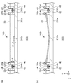
- FIGS. 2A to 2B are also used to describe the configuration of the solar cell module 100 and the gantry 200 in more detail.
- 2A and 2B are cross-sectional views along the y-axis showing the configuration of the solar cell system 500, and are cross-sectional views taken along the line A-A 'of FIG. 2A, the solar cell panel 30 has a shape that is longer in the y-axis direction than the z-axis direction, with the light-receiving surface facing the positive direction side of the z-axis and the back surface facing the negative direction side of the z-axis. Arranged. Further, each of the positive side end of the y axis of the solar cell panel 30 and the negative side end of the y axis corresponds to a part of the peripheral portion 32 in the xy plane of the solar cell panel 30.
- the first long frame 22a and the second long frame 22b are opposed frames in the solar cell module 100, and are configured in the same manner although they are bilaterally symmetric.
- the 1st long frame 22a is arrange
- the peripheral part 32 of the positive direction side of the y-axis of the solar cell panel 30 is engage
- the second long frame 22b is disposed on the negative direction side of the y axis of the solar cell panel 30, and the peripheral portion 32 on the negative direction side of the y axis of the solar cell panel 30 is fitted into the second long frame 22b. It is.
- the solar cell panel 30 is fixed to the long frame 22 with a butyl sealant or a silicone adhesive.
- the first long frame 22a and the second long frame 22b are formed in a substantially rectangular cross section from the portion into which the solar cell panel 30 is fitted toward the negative direction of the z axis.
- the first long frame 22a has a flange 40 that protrudes in the positive direction of the y axis at the negative side end, that is, the lower end of the z axis.
- the second long frame 22b has a flange 40 that protrudes in the negative direction of the y-axis at the end in the negative direction of the z-axis.
- the flange 40 protrudes from the lower end of the long frame 22 in the opposite direction to the solar cell panel 30.
- the first mount 200a extends in the y-axis direction.
- a first long frame 22a and a second long frame 22b are disposed on the surface of the first gantry 200a on the positive side of the z axis.
- the first mount 200a includes a first ridge-side fixing portion 204a on the positive side of the y-axis with respect to the flange 40 of the first long frame 22a.
- the first ridge-side fixing portion 204a is a hole for fixing the first long frame 22a, and is formed so that the flange nut 44 can be coupled thereto.
- the flange 40 of the first long frame 22a is pressed from the positive side of the z axis to the negative side by the presser 42 and the flange nut 44, whereby the first long frame 22a is fixed to the first base 200a.
- the first mount 200a includes a first eaves-side fixing portion 202a on the negative direction side of the y-axis with respect to the flange 40 of the second long frame 22b.
- the first eave-side fixing portion 202a is formed so that the flange nut 44 can be coupled, and fixes the second long frame 22b to the first gantry 200a.
- the third long frame 22c is disposed on the positive side of the first long frame 22a in the y-axis direction.
- the third long frame 22c is a frame in another solar cell module 100 disposed on the positive direction side of the y-axis of the solar cell module 100 described so far.
- the above-described presser 42 and flange nut 44 press the flange 40 of the third long frame 22c together with the flange 40 of the first long frame 22a.
- the first base 200a is provided with a first eaves side fixing portion 202a
- the second base 200b is provided with a second eaves side fixing portion 202b.
- the first eaves side fixing part 202a and the second eaves side fixing part 202b are collectively referred to as the eaves side fixing part 202.
- FIG. 1 does not show the first ridge side fixing portion 204a and the second ridge side fixing portion 204b, but the first gantry side fixing portion 204a is provided on the first gantry 200a, and the second ridge side 200b is provided with the second ridge.
- a side fixing portion 204b is provided.
- the first building side fixing unit 204a and the second building side fixing unit 204b are collectively referred to as the building side fixing unit 204.
- the eaves-side fixing unit 202 and the ridge-side fixing unit 204 have the same configuration, and may be collectively referred to simply as “fixing unit”.
- the configuration of the eaves side fixing portion 202 and the ridge side fixing portion 204 is not limited to the configuration in which the flange 40 is pressed by the presser 42 and the flange nut 44 as shown in FIG. Techniques may be used.
- the first contact member 210a is arranged to face.
- the first contact member 210a is made of metal, for example.
- the thickness of the first contact member 210a in the z-axis direction is indicated as “A”.
- the distance in the z-axis direction from the eaves side fixing unit 202 or the ridge side fixing unit 204 to the back surface of the solar cell panel 30 is indicated as “B”.
- A” ⁇ “B”.
- FIG. 2B shows a solar cell in the solar cell module 100 shown in FIG. 2A so that the central portion of the solar cell panel 30 in the y-axis direction moves to the negative direction side of the z-axis.
- FIG. 2B shows a solar cell in the solar cell module 100 shown in FIG. 2A so that the central portion of the solar cell panel 30 in the y-axis direction moves to the negative direction side of the z-axis.
- a part of the solar cell panel 30 is in contact with the first contact member 210a.
- portions other than a part of the solar cell panel 30 do not contact the first contact member 210a. A part of such a solar cell panel 30 will be further described with reference to FIG.
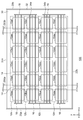
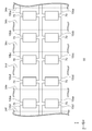
- FIG. 3 is a plan view showing the configuration of the solar cell module 100, which shows the configuration when the solar cell module 100 is viewed from the light receiving surface side.
- the solar cell module 100 includes the short frame 20, the long frame 22, and the solar cell panel 30.
- the solar battery panel 30 includes the eleventh solar battery cells 10aa,..., The 46th solar battery cell 10df, the inter-cell wiring member 14, the inter-group wiring member 16, and the group end wiring member, which are collectively referred to as the solar battery cell 10. 18 is included.
- the gantry 200 is disposed on the negative side of the z-axis of the solar cell module 100.
- Each of the plurality of solar cells 10 absorbs incident light and generates photovoltaic power.
- the solar cell 10 generates an electromotive force from the light absorbed on the light receiving surface and also generates a photoelectromotive force from the light absorbed on the back surface.
- the solar battery cell 10 is made of, for example, a semiconductor material such as crystalline silicon, gallium arsenide (GaAs), or indium phosphorus (InP).
- the structure of the solar battery cell 10 is not particularly limited, but here, as an example, it is assumed that crystalline silicon and amorphous silicon are stacked.
- the solar battery cell 10 has a quadrangular shape in the xy plane, but may have another shape, for example, an octagonal shape.
- a plurality of finger electrodes extending in the y-axis direction parallel to each other and a plurality extending in the x-axis direction so as to be orthogonal to the plurality of finger electrodes are provided on the light receiving surface and the back surface of each solar cell 10.
- Bus bar electrodes The bus bar electrode connects each of the plurality of finger electrodes.
- the plurality of solar cells 10 are arranged in a matrix on the xy plane.
- six solar cells 10 are arranged in the x-axis direction.
- the six solar cells 10 arranged side by side in the x-axis direction are connected in series by the inter-cell wiring material 14 to form one solar cell group 12.
- the solar cell group 12 can also be said to be a string.
- the first solar cell group 12a is formed by connecting the eleventh solar cell 10aa, the twelfth solar cell 10ab, ..., the sixteenth solar cell 10af.
- the second solar cell group 12b to the fourth solar cell group 12d are formed in the same manner.
- the four solar cell groups 12 are arranged in parallel in the y-axis direction.
- the number of the photovoltaic cells 10 arranged in the x-axis direction is larger than the number of the photovoltaic cells 10 arranged in the y-axis direction.
- the number of solar battery cells 10 included in the solar battery group 12 is not limited to “6”, and the number of solar battery groups 12 is not limited to “4”.
- the inter-cell wiring member 14 connects the bus bar electrode on one light receiving surface side of the adjacent solar cells 10 and the bus bar electrode on the other back surface side.
- three inter-cell wiring members 14 for connecting adjacent eleventh solar cells 10aa and twelfth solar cells 10ab are the bus bar electrodes on the back side of the eleventh solar cells 10aa and the twelfth solar cells.
- the bus bar electrode on the light receiving surface side of 10ab is electrically connected.
- Resin is used for connection between the inter-cell wiring member 14 and the bus bar electrode. This resin may be either conductive or non-conductive.
- the inter-cell wiring member 14 and the bus bar electrode are in direct contact with each other, and the inter-cell wiring member 14 and the bus bar electrode are mechanically connected to each other by a resin provided around the inter-cell wiring member 14 and the bus bar electrode. . Also, solder may be used instead of resin.
- the inter-group wiring member 16 extends in the y-axis direction and electrically connects two solar cell groups 12 adjacent to each other.
- the sixteenth solar cell 10af located at the positive end of the first solar cell group 12a on the x-axis and the twenty-sixth solar cell 10bf located at the positive end of the second solar cell group 12b on the x-axis. are electrically connected by the inter-group wiring member 16.
- the second solar cell group 12b and the third solar cell group 12c are electrically connected by the inter-group wiring member 16 on the negative direction side of the x axis
- the third solar cell group 12c and the fourth solar cell group. 12d is electrically connected by the inter-group wiring member 16 on the positive direction side of the x-axis.
- the plurality of solar cell groups 12 are connected in series by the inter-group wiring member 16.
- the inter-group wiring member 16 is not connected to the eleventh solar cell 10aa at the end in the negative x-axis direction of the first solar cell group 12a, and the group end wiring member 18 is connected instead.
- a lead-out wiring material (not shown) is connected to the group end wiring material 18.
- the extraction wiring material is a wiring material for extracting the electric power generated in the plurality of solar cells 10 to the outside of the solar cell module 100.
- the group end wiring member 18 is also connected to the forty-first solar cell 10da at the negative end on the x-axis side of the fourth solar cell group 12d.
- the first contact member 210a is surrounded by the 21st solar cell 10ba, the 22nd solar cell 10bb, the 31st solar cell 10ca, and the 32nd solar cell 10cb. It is arranged at a position corresponding to the portion.
- This portion is a portion that contacts the first contact member 210a when the solar cell panel 30 is bent in the direction of the main frame 200, that is, in the negative direction of the z-axis. Further, it can be said that this portion is a portion where the inter-cell wiring member 14 is avoided in the solar battery panel 30. Further, it can be said that this portion is a portion where the inter-group wiring member 16 is avoided in the solar cell panel 30.
- the portion avoiding them is a portion having relatively high resistance to contact. That is, when the solar cell panel 30 is bent, the first contact member 210a is disposed at a position where the first contact member 210a can contact a portion of the back surface of the solar cell panel 30 that is relatively resistant to contact.
- a translucent substrate is disposed on the light receiving surface side of the solar cell panel 30, and a back sheet as a back surface protection member is disposed on the back surface side.
- the sealing member is arrange
- a glass substrate, a translucent plastic, etc. are used for a translucent substrate
- a back film is a resin film such as PET (polyethylene terephthalate), and a laminated film having a structure in which an Al foil is sandwiched between resin films.
- a thermoplastic resin such as a resin film such as polyolefin, EVA (ethylene vinyl acetate), PVB (polyvinyl butyral), or polyimide is used.
- the contact member 210 is disposed on the gantry 200 for installing the solar cell module 100, even if the solar cell panel 30 is bent toward the gantry 200, the solar cell panel 30 is in contact with the solar cell panel 30.
- the working member 210 can be brought into contact.
- the solar cell panel 30 and the contact member 210 are contacted, contact of parts other than the part which contacts the contact member 210 in the solar cell panel 30 can be prevented.
- the thickness of the contact member 210 is greater than the distance from at least one of the eaves side fixing portion 202 and the ridge side fixing portion 204 to the lower surface of the solar cell panel 30. Because it is small, it can prevent normal contact.
- metal can be used for the contact member 210. Moreover, since a metal is used for the contact member 210, deterioration of the contact member 210 can be suppressed. In addition, since the deterioration of the contact member 210 is suppressed, periodic replacement of the contact member 210 can be eliminated. In addition, since the contact member 210 is disposed on the gantry 200, the configuration of the solar cell module 100 can be eliminated. In addition, since the contact member 210 is merely disposed on the gantry 200, damage due to the bending of the solar cell panel 30 can be easily prevented.
- the contact member 210 is disposed on the back surface of the solar cell panel 30 at a position where it can come into contact with a portion having relatively high resistance to contact. , It is possible to prevent contact of a portion having relatively low resistance to contact. Moreover, in the solar cell panel 30, since the contact member 210 is disposed at a position where it can come into contact with a portion avoiding the inter-cell wiring member 14, contact with the inter-cell wiring member 14 can be prevented. Further, in the solar cell panel 30, the contact member 210 is disposed at a position where it can come into contact with a portion that avoids the inter-group wiring member 16, so that contact with the inter-group wiring member 16 can be prevented.
- the outline of this example is as follows.
- the gantry 200 according to an aspect of the present invention is a gantry 200 for installing the solar cell module 100 in which the long frame 22 is disposed on the peripheral edge portion 32 of the solar cell panel 30 including an upper surface and a lower surface facing each other.
- the solar cell module 100 is arranged between the plurality of eaves-side fixing portions 202 and the ridge-side fixing portion 204 that fix each of the opposed long frames 22, and between the plurality of eaves-side fixing portions 202 and the ridge-side fixing portion 204.
- the contact member 210 is provided.
- the thickness of the contact member 210 is smaller than the distance from at least one of the plurality of eaves side fixing portions 202 and the ridge side fixing portion 204 to the lower surface of the solar cell panel 30. .
- the contact member 210 is disposed at a position where it can contact a portion of the lower surface of the solar cell panel 30 that is relatively resistant to contact. Also good.
- the contact member 210 may be disposed at a position in the solar battery panel 30 that can contact a portion that avoids the inter-cell wiring member 14 for connecting the solar battery cells 10.
- the contact member 210 may be disposed at a position in the solar battery panel 30 that can contact a portion avoiding the inter-group wiring member 16 for connecting the strings of the solar battery cells 10.
- This solar cell system 500 includes a solar cell module 100 in which a long frame 22 is disposed at a peripheral edge portion 32 of a solar cell panel 30 including an upper surface and a lower surface that are opposite to each other, and a long frame 22 that faces the solar cell module 100.
- the gantry 200 includes a plurality of eaves-side fixing portions 202 and a contact member 210 disposed between the ridge-side fixing portions 204.
- the thickness of the contact member 210 is smaller than the distance from at least one of the plurality of eaves side fixing portions 202 and the ridge side fixing portion 204 to the lower surface of the solar cell panel 30. .
- Example 2 is related with the solar cell module installed in a mount. Similarly to Example 1, when the solar cell panel is bent in the direction of the roof, the solar cell panel may be damaged by contacting the gantry. In order to prevent damage to the solar cell panel, in Example 1, a contact member is disposed on the gantry. On the other hand, in Example 2, the contact member is attached to the back surface of the solar cell panel 30. Here, it demonstrates centering on the difference with Example 1. FIG.
- FIG. 4 is a perspective view showing a configuration of a solar cell system 500 according to Embodiment 2 of the present invention. Although this is shown in the same manner as FIG. 1, the gantry 200 does not include the contact member 210, and the solar cell panel 30 includes the contact member 34. A contact member 34 is attached to the back surface of the solar cell panel 30.
- the contact member 34 has a rectangular shape in which the x-axis direction is longer than the y-axis direction on the lower surface of the solar cell panel 30. It can be said that the shape of the contact member 34 is long in the direction in which the plurality of mounts 200 are arranged.
- FIGS. 5A to 5B are also used to describe the configuration of the solar cell module 100 and the gantry 200 in more detail.
- FIGS. 5A and 5B are cross-sectional views along the y-axis showing the configuration of the solar cell system 500, and are cross-sectional views taken along the line B-B ′ of FIG.
- the contact member 34 is disposed on the back side of the solar cell panel 30 so as to face the gantry 200.
- the contact member 34 is made of, for example, metal.
- the thickness of the contact member 34 in the z-axis direction is indicated as “C”.
- the distance in the z-axis direction from the eaves side fixing part 202 or the ridge side fixing part 204 to the back surface of the solar cell panel 30 is indicated as “D”. This corresponds to the distance in the z-axis direction from the lower end of the long frame 22 to the back surface of the solar cell panel 30.
- FIG. 5B shows a solar cell in the solar cell module 100 shown in FIG. 5A such that the central portion in the y-axis direction of the solar cell panel 30 moves to the negative direction side of the z-axis.
- FIG. 5B shows a solar cell in the solar cell module 100 shown in FIG. 5A such that the central portion in the y-axis direction of the solar cell panel 30 moves to the negative direction side of the z-axis.
- It is sectional drawing which shows a structure when the panel 30 bends.
- the contact member 34 in the solar cell panel 30 contacts the first mount 200a.
- parts other than the contact member 34 in the solar cell panel 30 do not contact the first mount 200a. The position where the contact member 34 in the solar cell panel 30 is arranged will be further described with reference to FIG.
- FIG. 6 is a plan view showing the configuration of the solar cell module 100. This is shown in the same manner as FIG. 3, but the gantry 200 does not include the contact member 210, and the solar cell panel 30 includes the contact member 34.
- the contact member 34 is attached to a portion sandwiched between the second solar cell group 12b and the third solar cell group 12c. This part is a part which contacts the 1st mount 200a, when the solar cell panel 30 bends in the direction of the main mount 200, ie, the negative direction of the z-axis. Further, it can be said that this portion is a portion where the inter-cell wiring member 14 is avoided in the solar battery panel 30.
- this portion is a portion where the inter-group wiring member 16 is avoided in the solar cell panel 30.
- the inter-cell wiring member 14 and the inter-group wiring member 16 are liable to be damaged by contact. Therefore, a portion avoiding these is a portion having relatively high resistance to contact. That is, the contact member 34 is attached to a portion of the back surface of the solar cell panel 30 that is relatively resistant to contact when the solar cell panel 30 is bent.
- FIG. 7 is a plan view showing another configuration of the solar cell module 100, and is shown in the same manner as FIG.
- the portion where the inter-cell wiring member 14 is disposed is a portion having a relatively high resistance to contact.
- the first contact member 34a is attached so as to overlap the inter-cell wiring member 14 in the central portion in the y-axis direction of the second solar cell group 12b.
- the second contact member 34b is attached so as to overlap the inter-cell wiring member 14 at the center portion in the y-axis direction of the third solar cell group 12c.
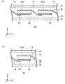
- FIGS. 8A to 8B are cross-sectional views showing the configuration of the solar cell module 100.
- FIG. FIG. 8A shows a configuration for shortening the length of the inter-cell wiring member 14.
- the solar battery panel 30 includes a twenty-second solar battery cell 10bb, a twenty-third solar battery cell 10bc, an inter-cell wiring member 14, a first protective member 50, a first sealing member 52, a second sealing member 54, and a second protective member. 56 and bus bar electrodes 58.
- the first sealing member 52 and the second protective member 56 correspond to the above-described translucent substrate and back sheet, respectively.
- a bus bar electrode 58 is disposed on the back surface of the solar battery cell 10. In the configuration so far, the bus bar electrode 58 is disposed only by omitting the illustration of the bus bar electrode 58.
- the inter-cell wiring member 14 disposed on the light receiving surface of the solar battery cell 10 extends in the direction of the back surface of the adjacent solar battery cell 10 and is connected to the bus bar electrode 58 of the adjacent solar battery cell 10 by solder or conductive resin.
- the inter-cell wiring member 14 is connected to the entire surface of the bus bar electrode 58, but here, the inter-cell wiring member 14 is connected only to a part of the adhesion region 60 of the bus bar electrode 58. .
- attaching the wiring material 14 between cells and the bus-bar electrode 58 becomes small, the tolerance by contact can become low. Therefore, the contact member 34 is attached so as to consider the adhesion region 60.
- FIG. 8B is a cross-sectional view showing another configuration in which the inter-cell wiring material 14 similar to that in FIG. 8A is used.
- a bus bar electrode 58 is disposed on the back surface of the twenty-second solar battery cell 10bb, and a wiring member 62 and an inter-cell wiring member 14 are sequentially disposed on the negative side of the z-axis of the bus bar electrode 58.
- the inter-cell wiring member 14 is connected only to the adhesion region 60 from the negative direction side of the z-axis.
- solder or conductive resin is used to connect the bus bar electrode 58 and the wiring member 62, and solder is used to connect the wiring member 62 and the inter-cell wiring member 14.
- the bus-bar electrode 58 is arrange
- FIG. 9 is a plan view showing still another configuration of the solar cell module 100, and is shown in the same manner as FIG. FIG. 8A corresponds to a cross-sectional view taken along the line C-C ′ of FIG.
- the adhesion region 60 in each solar battery cell 10 is indicated by hatching.
- Each contact member 34 has a rectangular shape that is longer in the y-axis direction than in the x-axis direction, and is disposed on the back surface of the solar battery panel 30 so as to penetrate the central portion of each solar battery cell 10. That is, each contact member 34 is attached to a portion avoiding the adhesion region 60.
- FIG. 10 is a plan view showing still another configuration of the solar cell module 100, which shows a configuration when the solar cell module 100 is viewed from the back side.
- the solar cell module 100 here includes a back electrode type solar cell 10. Since the back electrode type solar battery cell 10 is a known technique, the description thereof is omitted here.
- each photovoltaic cell 10 is connected by the wiring material 70.
- Each contact member 34 has a rectangular shape that is longer in the y-axis direction than in the x-axis direction, and is disposed on the back surface of the solar battery panel 30 so as to penetrate the central portion of each solar battery cell 10. That is, each contact member 34 is attached to a portion avoiding the wiring member 70.
- the contact member 34 and the gantry 200 are brought into contact with each other even when the solar cell panel 30 is bent toward the gantry 200. Can do. Further, since the contact member 34 and the gantry 200 are brought into contact with each other, contact of portions other than the contact member 34 in the solar cell panel 30 can be prevented. Further, in the direction from the back surface of the solar cell panel 30 to the light receiving surface, the thickness of the contact member 34 is larger than the distance from at least one of the eaves side fixing portion 202 and the ridge side fixing portion 204 to the lower surface of the solar cell panel 30. Because it is small, it can prevent normal contact.
- metal can be used for the contact member 34.
- a metal is used for the contact member 34, deterioration of the contact member 34 can be suppressed. Further, since the deterioration of the contact member 34 is suppressed, it is possible to eliminate periodic replacement of the contact member 34. Further, since the solar cell panel 30 is simply attached to the contact member 34, damage due to the bending of the solar cell panel 30 can be easily prevented.
- the contact member 34 is attached to a portion of the back surface of the solar cell panel 30 where the contact resistance is relatively high. Therefore, it is possible to prevent contact with a low part.
- the contact member 34 is attached to a portion of the solar battery panel 30 that avoids the inter-cell wiring member 14
- contact with the inter-cell wiring member 14 can be prevented.
- the contact member 34 is attached to a portion of the solar cell panel 30 that avoids the inter-group wiring member 16
- the contact member 34 has a rectangular shape in which one direction is longer than the other direction, contact between the solar cell panel 30 and the gantry 200 can be prevented even if the interval between the gantry 200 changes.
- Yet another embodiment of the present invention is a solar cell module 100.
- the solar cell module 100 is attached to a solar cell panel 30 including an upper surface and a lower surface facing opposite to each other, a long frame 22 disposed on a peripheral edge 32 of the solar cell panel 30, and a lower surface of the solar cell panel 30.
- a contact member 34 In the direction from the lower surface to the upper surface of the solar cell panel 30, the thickness of the contact member 34 is smaller than the distance from the lower end of the long frame 22 to the lower surface of the solar cell panel 30.
- the contact member 34 may be attached to a portion of the lower surface of the solar cell panel 30 that is relatively resistant to contact.
- the contact member 34 may be attached to a portion of the solar battery panel 30 that avoids the inter-cell wiring member 14 for connecting the solar battery cells 10.
- the contact member 34 may be attached to a portion of the solar battery panel 30 that avoids the inter-group wiring member 16 for connecting the strings of the solar battery cells 10.
- the contact member 34 may have a rectangular shape in which one direction is longer than another direction on the lower surface of the solar cell panel 30.
- Still another embodiment of the present invention is also a solar cell system 500.
- This solar cell system 500 includes a solar cell module 100 in which a long frame 22 is disposed at a peripheral edge portion 32 of a solar cell panel 30 including an upper surface and a lower surface that are opposite to each other, and a long frame 22 that faces the solar cell module 100.
- the solar cell module 100 further includes a contact member 34 attached to the lower surface of the solar cell panel 30.
- the thickness of the contact member 34 is smaller than the distance from at least one of the plurality of eaves side fixing portions 202 and the ridge side fixing portion 204 to the lower surface of the solar cell panel 30. .
Landscapes
- Engineering & Computer Science (AREA)
- Architecture (AREA)
- Civil Engineering (AREA)
- Structural Engineering (AREA)
- Roof Covering Using Slabs Or Stiff Sheets (AREA)
- Photovoltaic Devices (AREA)
Abstract
L'invention concerne un module photovoltaïque 100, dans lequel un cadre long 22 est disposé sur la périphérie 32 d'un panneau photovoltaïque 30 qui comprend une face supérieure et une face inférieure opposées l'une à l'autre, qui est installé sur un support 200. Une unité d'ancrage côté avant-toit 202 et une unité d'ancrage côté faîtage 204 ancrent chacun des cadres longs opposés 22 dans le panneau photovoltaïque 30. Un élément de contact 210 est disposé entre l'unité d'ancrage côté avant-toit 202 et l'unité d'ancrage côté faîtage 204. L'épaisseur de l'élément de contact 210 dans la direction allant de la face inférieure à la face supérieure du panneau photovoltaïque 30 est inférieure à la distance allant de l'unité d'ancrage côté avant-toit 202 ou de l'unité d'ancrage côté faîtage 204 à la face inférieure du panneau photovoltaïque 30.
Priority Applications (1)
| Application Number | Priority Date | Filing Date | Title |
|---|---|---|---|
| JP2018504472A JP6807551B2 (ja) | 2016-03-08 | 2017-03-06 | 架台、太陽電池モジュール、太陽電池システム |
Applications Claiming Priority (2)
| Application Number | Priority Date | Filing Date | Title |
|---|---|---|---|
| JP2016044330 | 2016-03-08 | ||
| JP2016-044330 | 2016-03-08 |
Publications (1)
| Publication Number | Publication Date |
|---|---|
| WO2017154826A1 true WO2017154826A1 (fr) | 2017-09-14 |
Family
ID=59790465
Family Applications (1)
| Application Number | Title | Priority Date | Filing Date |
|---|---|---|---|
| PCT/JP2017/008740 Ceased WO2017154826A1 (fr) | 2016-03-08 | 2017-03-06 | Support, module photovoltaïque et système photovoltaïque |
Country Status (2)
| Country | Link |
|---|---|
| JP (1) | JP6807551B2 (fr) |
| WO (1) | WO2017154826A1 (fr) |
Cited By (2)
| Publication number | Priority date | Publication date | Assignee | Title |
|---|---|---|---|---|
| WO2022140682A1 (fr) * | 2020-12-23 | 2022-06-30 | Array Technologies, Inc. | Limiteur de déviation de module photovoltaïque |
| US11581846B2 (en) | 2020-12-23 | 2023-02-14 | Array Technologies, Inc. | Photovoltaic module deflection limiter |
Citations (5)
| Publication number | Priority date | Publication date | Assignee | Title |
|---|---|---|---|---|
| JP2003105940A (ja) * | 2001-09-28 | 2003-04-09 | Sekisui Chem Co Ltd | 太陽電池モジュールの設置構造 |
| WO2009107776A1 (fr) * | 2008-02-28 | 2009-09-03 | 京セラ株式会社 | Système de génération d'énergie solaire |
| JP2011231477A (ja) * | 2010-04-26 | 2011-11-17 | Fp Corporation Ltd | 太陽電池モジュールの設置構造 |
| WO2012017957A1 (fr) * | 2010-08-03 | 2012-02-09 | 昭和シェル石油株式会社 | Module de cellule solaire |
| JP2015227558A (ja) * | 2014-05-30 | 2015-12-17 | パナソニックIpマネジメント株式会社 | 太陽光発電装置 |
-
2017
- 2017-03-06 WO PCT/JP2017/008740 patent/WO2017154826A1/fr not_active Ceased
- 2017-03-06 JP JP2018504472A patent/JP6807551B2/ja not_active Expired - Fee Related
Patent Citations (5)
| Publication number | Priority date | Publication date | Assignee | Title |
|---|---|---|---|---|
| JP2003105940A (ja) * | 2001-09-28 | 2003-04-09 | Sekisui Chem Co Ltd | 太陽電池モジュールの設置構造 |
| WO2009107776A1 (fr) * | 2008-02-28 | 2009-09-03 | 京セラ株式会社 | Système de génération d'énergie solaire |
| JP2011231477A (ja) * | 2010-04-26 | 2011-11-17 | Fp Corporation Ltd | 太陽電池モジュールの設置構造 |
| WO2012017957A1 (fr) * | 2010-08-03 | 2012-02-09 | 昭和シェル石油株式会社 | Module de cellule solaire |
| JP2015227558A (ja) * | 2014-05-30 | 2015-12-17 | パナソニックIpマネジメント株式会社 | 太陽光発電装置 |
Cited By (3)
| Publication number | Priority date | Publication date | Assignee | Title |
|---|---|---|---|---|
| WO2022140682A1 (fr) * | 2020-12-23 | 2022-06-30 | Array Technologies, Inc. | Limiteur de déviation de module photovoltaïque |
| US11581846B2 (en) | 2020-12-23 | 2023-02-14 | Array Technologies, Inc. | Photovoltaic module deflection limiter |
| CN116762271A (zh) * | 2020-12-23 | 2023-09-15 | 阵列科技股份有限公司 | 光伏模块挠曲限制器 |
Also Published As
| Publication number | Publication date |
|---|---|
| JPWO2017154826A1 (ja) | 2018-11-29 |
| JP6807551B2 (ja) | 2021-01-06 |
Similar Documents
| Publication | Publication Date | Title |
|---|---|---|
| US9948232B2 (en) | Method for fabricating flexible solar panel module | |
| JP6624418B2 (ja) | 太陽電池モジュール | |
| TWI429096B (zh) | Solar cell module and manufacturing method thereof | |
| US11728451B2 (en) | Flexible laminates for solar modules | |
| US20150171788A1 (en) | Solar module junction box bypass diode | |
| US20150188483A1 (en) | Photovoltaic system and holder unit | |
| US8418416B2 (en) | Solar cell module | |
| EP3067937A1 (fr) | Module de cellule solaire | |
| EP2747151A2 (fr) | Appareil de génération de puissance photovoltaïque | |
| US9530919B2 (en) | Solar cell module | |
| US9972726B2 (en) | Photovoltaic apparatus | |
| JP6807551B2 (ja) | 架台、太陽電池モジュール、太陽電池システム | |
| JP6624535B2 (ja) | 太陽電池モジュール | |
| KR20150031975A (ko) | 태양전지 모듈 | |
| JP2007180314A (ja) | 太陽電池モジュール | |
| EP4216285A1 (fr) | Cellule solaire | |
| JP2009238876A (ja) | 太陽電池モジュール | |
| US20250318285A1 (en) | Photovoltaic module and interconnector | |
| JP2005235842A (ja) | 太陽電池モジュール | |
| JP2001311281A (ja) | 太陽電池モジュールの設置方法 | |
| KR20130101818A (ko) | 태양전지 모듈 | |
| WO2016103626A1 (fr) | Boîte de bornes et module de batterie solaire sur lequel est fixée ladite boîte de bornes | |
| JP2017055525A (ja) | 太陽電池モジュールの設置構造及び設置方法 | |
| JP2013048232A (ja) | 太陽電池モジュール | |
| JP2013077693A (ja) | 太陽電池モジュールおよびそれを用いた太陽電池アレイ |
Legal Events
| Date | Code | Title | Description |
|---|---|---|---|
| ENP | Entry into the national phase |
Ref document number: 2018504472 Country of ref document: JP Kind code of ref document: A |
|
| NENP | Non-entry into the national phase |
Ref country code: DE |
|
| 121 | Ep: the epo has been informed by wipo that ep was designated in this application |
Ref document number: 17763166 Country of ref document: EP Kind code of ref document: A1 |
|
| 122 | Ep: pct application non-entry in european phase |
Ref document number: 17763166 Country of ref document: EP Kind code of ref document: A1 |