WO2017155000A1 - Dispositif d'affichage d'image - Google Patents
Dispositif d'affichage d'image Download PDFInfo
- Publication number
- WO2017155000A1 WO2017155000A1 PCT/JP2017/009331 JP2017009331W WO2017155000A1 WO 2017155000 A1 WO2017155000 A1 WO 2017155000A1 JP 2017009331 W JP2017009331 W JP 2017009331W WO 2017155000 A1 WO2017155000 A1 WO 2017155000A1
- Authority
- WO
- WIPO (PCT)
- Prior art keywords
- light source
- light
- video display
- display device
- unit
- Prior art date
- Legal status (The legal status is an assumption and is not a legal conclusion. Google has not performed a legal analysis and makes no representation as to the accuracy of the status listed.)
- Ceased
Links
Images


Classifications
-
- H—ELECTRICITY
- H05—ELECTRIC TECHNIQUES NOT OTHERWISE PROVIDED FOR
- H05B—ELECTRIC HEATING; ELECTRIC LIGHT SOURCES NOT OTHERWISE PROVIDED FOR; CIRCUIT ARRANGEMENTS FOR ELECTRIC LIGHT SOURCES, IN GENERAL
- H05B45/00—Circuit arrangements for operating light-emitting diodes [LED]
- H05B45/20—Controlling the colour of the light
-
- F—MECHANICAL ENGINEERING; LIGHTING; HEATING; WEAPONS; BLASTING
- F16—ENGINEERING ELEMENTS AND UNITS; GENERAL MEASURES FOR PRODUCING AND MAINTAINING EFFECTIVE FUNCTIONING OF MACHINES OR INSTALLATIONS; THERMAL INSULATION IN GENERAL
- F16M—FRAMES, CASINGS OR BEDS OF ENGINES, MACHINES OR APPARATUS, NOT SPECIFIC TO ENGINES, MACHINES OR APPARATUS PROVIDED FOR ELSEWHERE; STANDS; SUPPORTS
- F16M11/00—Stands or trestles as supports for apparatus or articles placed thereon ; Stands for scientific apparatus such as gravitational force meters
- F16M11/20—Undercarriages with or without wheels
- F16M11/22—Undercarriages with or without wheels with approximately constant height, e.g. with constant length of column or of legs
-
- F—MECHANICAL ENGINEERING; LIGHTING; HEATING; WEAPONS; BLASTING
- F21—LIGHTING
- F21V—FUNCTIONAL FEATURES OR DETAILS OF LIGHTING DEVICES OR SYSTEMS THEREOF; STRUCTURAL COMBINATIONS OF LIGHTING DEVICES WITH OTHER ARTICLES, NOT OTHERWISE PROVIDED FOR
- F21V33/00—Structural combinations of lighting devices with other articles, not otherwise provided for
- F21V33/0004—Personal or domestic articles
- F21V33/0052—Audio or video equipment, e.g. televisions, telephones, cameras or computers; Remote control devices therefor
-
- G—PHYSICS
- G02—OPTICS
- G02B—OPTICAL ELEMENTS, SYSTEMS OR APPARATUS
- G02B5/00—Optical elements other than lenses
- G02B5/02—Diffusing elements; Afocal elements
- G02B5/0205—Diffusing elements; Afocal elements characterised by the diffusing properties
-
- G—PHYSICS
- G02—OPTICS
- G02B—OPTICAL ELEMENTS, SYSTEMS OR APPARATUS
- G02B6/00—Light guides; Structural details of arrangements comprising light guides and other optical elements, e.g. couplings
-
- G—PHYSICS
- G02—OPTICS
- G02B—OPTICAL ELEMENTS, SYSTEMS OR APPARATUS
- G02B6/00—Light guides; Structural details of arrangements comprising light guides and other optical elements, e.g. couplings
- G02B6/0001—Light guides; Structural details of arrangements comprising light guides and other optical elements, e.g. couplings specially adapted for lighting devices or systems
- G02B6/0011—Light guides; Structural details of arrangements comprising light guides and other optical elements, e.g. couplings specially adapted for lighting devices or systems the light guides being planar or of plate-like form
- G02B6/0013—Means for improving the coupling-in of light from the light source into the light guide
- G02B6/0023—Means for improving the coupling-in of light from the light source into the light guide provided by one optical element, or plurality thereof, placed between the light guide and the light source, or around the light source
- G02B6/0025—Diffusing sheet or layer; Prismatic sheet or layer
-
- G—PHYSICS
- G02—OPTICS
- G02B—OPTICAL ELEMENTS, SYSTEMS OR APPARATUS
- G02B6/00—Light guides; Structural details of arrangements comprising light guides and other optical elements, e.g. couplings
- G02B6/0001—Light guides; Structural details of arrangements comprising light guides and other optical elements, e.g. couplings specially adapted for lighting devices or systems
- G02B6/0096—Light guides; Structural details of arrangements comprising light guides and other optical elements, e.g. couplings specially adapted for lighting devices or systems the lights guides being of the hollow type
-
- G—PHYSICS
- G09—EDUCATION; CRYPTOGRAPHY; DISPLAY; ADVERTISING; SEALS
- G09F—DISPLAYING; ADVERTISING; SIGNS; LABELS OR NAME-PLATES; SEALS
- G09F9/00—Indicating arrangements for variable information in which the information is built-up on a support by selection or combination of individual elements
-
- G—PHYSICS
- G09—EDUCATION; CRYPTOGRAPHY; DISPLAY; ADVERTISING; SEALS
- G09G—ARRANGEMENTS OR CIRCUITS FOR CONTROL OF INDICATING DEVICES USING STATIC MEANS TO PRESENT VARIABLE INFORMATION
- G09G3/00—Control arrangements or circuits, of interest only in connection with visual indicators other than cathode-ray tubes
- G09G3/20—Control arrangements or circuits, of interest only in connection with visual indicators other than cathode-ray tubes for presentation of an assembly of a number of characters, e.g. a page, by composing the assembly by combination of individual elements arranged in a matrix no fixed position being assigned to or needed to be assigned to the individual characters or partial characters
- G09G3/22—Control arrangements or circuits, of interest only in connection with visual indicators other than cathode-ray tubes for presentation of an assembly of a number of characters, e.g. a page, by composing the assembly by combination of individual elements arranged in a matrix no fixed position being assigned to or needed to be assigned to the individual characters or partial characters using controlled light sources
- G09G3/30—Control arrangements or circuits, of interest only in connection with visual indicators other than cathode-ray tubes for presentation of an assembly of a number of characters, e.g. a page, by composing the assembly by combination of individual elements arranged in a matrix no fixed position being assigned to or needed to be assigned to the individual characters or partial characters using controlled light sources using electroluminescent panels
- G09G3/32—Control arrangements or circuits, of interest only in connection with visual indicators other than cathode-ray tubes for presentation of an assembly of a number of characters, e.g. a page, by composing the assembly by combination of individual elements arranged in a matrix no fixed position being assigned to or needed to be assigned to the individual characters or partial characters using controlled light sources using electroluminescent panels semiconductive, e.g. using light-emitting diodes [LED]
-
- H—ELECTRICITY
- H04—ELECTRIC COMMUNICATION TECHNIQUE
- H04N—PICTORIAL COMMUNICATION, e.g. TELEVISION
- H04N5/00—Details of television systems
- H04N5/64—Constructional details of receivers, e.g. cabinets or dust covers
-
- F—MECHANICAL ENGINEERING; LIGHTING; HEATING; WEAPONS; BLASTING
- F16—ENGINEERING ELEMENTS AND UNITS; GENERAL MEASURES FOR PRODUCING AND MAINTAINING EFFECTIVE FUNCTIONING OF MACHINES OR INSTALLATIONS; THERMAL INSULATION IN GENERAL
- F16M—FRAMES, CASINGS OR BEDS OF ENGINES, MACHINES OR APPARATUS, NOT SPECIFIC TO ENGINES, MACHINES OR APPARATUS PROVIDED FOR ELSEWHERE; STANDS; SUPPORTS
- F16M2200/00—Details of stands or supports
- F16M2200/08—Foot or support base
-
- H—ELECTRICITY
- H04—ELECTRIC COMMUNICATION TECHNIQUE
- H04N—PICTORIAL COMMUNICATION, e.g. TELEVISION
- H04N21/00—Selective content distribution, e.g. interactive television or video on demand [VOD]
- H04N21/40—Client devices specifically adapted for the reception of or interaction with content, e.g. set-top-box [STB]; Operations thereof
- H04N21/41—Structure of client; Structure of client peripherals
- H04N21/422—Input-only peripherals, i.e. input devices connected to specially adapted client devices, e.g. global positioning system [GPS]
- H04N21/42202—Input-only peripherals, i.e. input devices connected to specially adapted client devices, e.g. global positioning system [GPS] environmental sensors, e.g. for detecting temperature, luminosity, pressure, earthquakes
-
- H—ELECTRICITY
- H04—ELECTRIC COMMUNICATION TECHNIQUE
- H04N—PICTORIAL COMMUNICATION, e.g. TELEVISION
- H04N5/00—Details of television systems
- H04N5/44—Receiver circuitry for the reception of television signals according to analogue transmission standards
- H04N5/57—Control of contrast or brightness
- H04N5/58—Control of contrast or brightness in dependence upon ambient light
Definitions
- the present disclosure relates to a video display device that displays video, and particularly relates to a video display device that can emit light from the periphery of a display unit.
- a video display device that illuminates light around a display unit with light generated from a display unit (display panel) is known (see, for example, Patent Document 1).
- the conventional video display apparatus illuminates the surrounding area with the light generated by the display unit, the light generated by the display unit is difficult to achieve harmony with the surroundings.
- the light generated by the display unit is difficult to achieve harmony with the surroundings.
- the present disclosure has been made to solve such a problem, and provides a video display device that produces a floating feeling of a display unit.
- an aspect of the video display device includes a display unit that displays video, and at least a part of the display unit that is translucent and supports the display unit in a standing state
- An image display device comprising: one support part; and at least one first light source that is provided in the display unit and irradiates at least a part of the support part.
- the floating feeling of the display unit can be produced.
- FIG. 1 is a perspective view showing a video display apparatus according to Embodiment 1.
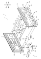
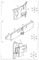
- FIG. FIG. 2 is an exploded perspective view showing the video display apparatus according to the first embodiment.
- FIG. 3 is a perspective view showing the first right connection fitting and the right first light source of the video display apparatus according to Embodiment 1.
- 4 is a perspective view showing a right light guide of the video display apparatus according to Embodiment 1.
- FIG. 5 is a perspective view showing a right end cover body of the video display apparatus according to Embodiment 1.
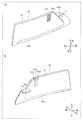
- FIG. FIG. 6A is a perspective view seen from the right side of the translucent portion of the video display device according to the first embodiment.
- FIG. 6B is a perspective view seen from the left side of the translucent part of the video display device according to the first embodiment.
- FIG. 7 is a perspective view showing the main body of the video display apparatus according to Embodiment 1.
- FIG. 8 is a perspective view showing a right support portion of the video display apparatus according to Embodiment 1.
- FIG. 9A is a perspective view showing the mounting bracket and the upper second light source of the video display device according to the first embodiment.
- FIG. 9B is a perspective view showing the mounting bracket and the lower second light source of the video display device according to the first embodiment.
- FIG. 9C is a perspective view showing the mounting bracket and the left second light source of the video display device according to the first embodiment.
- FIG. 10A is a partially exploded cross-sectional perspective view showing the upper side portion of the rear cabinet of the video display apparatus according to Embodiment 1.
- FIG. 10B is a perspective view of the diffusion plate of the video display device according to the first embodiment.
- FIG. 11 is a partially enlarged cross-sectional perspective view showing the rear cabinet of the video display apparatus according to Embodiment 1.
- FIG. 12 is a block diagram illustrating the video display apparatus according to the first embodiment.
- FIG. 13 is a schematic diagram illustrating light that is transmitted through the right light guide and the light transmitting unit in the video display device according to the first embodiment.
- FIG. 14 shows a state in which the right first light source, the left first light source, the upper second light source, the lower second light source, the left second light source, and the right second light source of the video display device according to Embodiment 1 are turned on. It is a schematic diagram shown.
- FIG. 15 is a block diagram showing a video display apparatus according to the second embodiment.
- FIG. 16 is a flowchart showing the operation of the video display apparatus according to the second embodiment.
- FIG. 1 is a perspective view showing a video display device 1 according to the first embodiment.
- the placement side of the device is defined as the downward direction
- the direction opposite to the placement side is defined as the upward direction
- the front, rear, left, and right directions are displayed.
- . 2 are displayed in correspondence with the directions shown in FIG. 1.
- an up-down direction, a left-right direction, and the front-back direction change with usage modes, it is not limited to this. The same applies to the subsequent drawings.
- the video display device 1 is, for example, a flat panel display type liquid crystal television receiver.
- the video display device 1 includes a display unit 3, a right support 5 (an example of a support), and a left support 7 (an example of a support).
- the display unit 3 has a panel body 9 and a rear cabinet 11, and is formed in a rectangular flat panel as a whole.
- the panel main body 9 has a display panel 13 and a front cabinet 15.
- the display panel 13 is disposed inside the front cabinet 15.
- a display panel 13 on which an image is displayed is provided in front of the panel main body 9.
- the front cabinet 15 is formed in a rectangular frame shape, and is arranged so as to cover the outer peripheral portion of the display screen of the panel body 9.
- the rear cabinet 11 is arranged so as to cover the entire back surface of the panel body 9 and is connected to the front cabinet 15. As a result, a display screen of the liquid crystal panel is arranged in front of the display unit 3.
- FIG. 2 is an exploded perspective view showing the video display device 1 according to the first embodiment.
- FIG. 3 is a perspective view showing the first right connection fitting 21 and the right first light source 31 of the video display device 1 according to the first embodiment.
- the first right connecting bracket 21 is fixed to the right mounting portion 9 a of FIG. 2 formed on the lower right side of the panel main body portion 9 with screws.
- the first right connection fitting 21 includes a flat plate portion 21a extending vertically and a plate-like holding portion 21b formed on the right side of the flat plate portion 21a.
- two screw holes for fixing the second right connection fitting 22 are formed vertically.
- a connecting piece extending forward is formed on the flat plate portion 21a, and is attached to the panel body 9 by a screw that passes through the connecting piece.
- the holding unit 21b holds the right first light source 31 (an example of the first light source) so as to irradiate light toward the rear side.
- the first left connection fitting 23 is fixed to the left mounting portion 9 b formed on the lower left side of the panel body 9 with screws.
- the first left connecting fitting 23 also has a flat plate portion extending vertically and a holding portion formed on the left side of the flat plate portion. In the flat plate portion, two screw holes for fixing the second left connecting metal fitting 24 are formed vertically.
- a connecting piece extending forward is formed on the flat plate portion, and is attached to the panel main body portion 9 with a screw that passes through the connecting piece.
- the holding unit holds the left first light source 32 (an example of the first light source) so as to emit light toward the rear side.
- the right first light source 31 and the left first light source 32 are electrically connected to a control unit 10a described later.
- the right first light source 31 and the left first light source 32 are SMD (Surface Mount Device) type LED elements.
- the SMD type LED element is a package type LED element in which an LED chip (light emitting element) is mounted in a resin-molded cavity, and a phosphor-containing resin is sealed in the cavity.
- the right first light source 31 and the left first light source 32 are not limited to such a configuration, and a COB (LED chip directly mounted on a substrate (not shown) of the right first light source 31).
- a Chip On Board type light emitting module may be used.
- the light emitting elements included in the right first light source 31 and the left first light source 32 are not limited to LEDs.
- a semiconductor light emitting element such as a semiconductor laser, an organic EL (Electro Luminescence), or an inorganic EL.
- Other solid state light emitting devices such as EL devices may be used.
- a right light guide 41 is provided in the rear direction (irradiation direction) of the right first light source 31.
- a left light guide 45 is provided in the rear direction (irradiation direction) of the left first light source 32.
- the right light guide 41 and the left light guide 45 are transparent optical members that transmit light.
- the right light guide 41 and the left light guide 45 are translucent resins such as polycarbonate and acrylic, but may be formed of any other material.
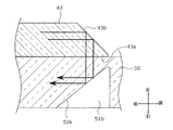
- FIG. 4 is a perspective view showing the right light guide 41 of the video display device 1 according to the first embodiment.
- the right light guide 41 has a columnar structure extending vertically.
- the right light guide 41 has an extending part 42 and an insertion part 43.
- the extending part 42 has an incident surface 42a on which light from the right first light source 31 is incident, a first reflecting surface 42b, and a second reflecting surface 42c.
- the incident surface 42a faces forward and is formed above the right light guide 41.
- the incident surface 42a is preferably substantially orthogonal to the rear direction irradiated by the right first light source 31.
- the first reflecting surface 42b is located on the rear side of the incident surface 42a.
- the first reflective surface 42b is inclined downward from the front to the rear so that the extended surface of the incident surface 42a and the extended surface of the first reflective surface 42b intersect.
- the second reflecting surface 42c is located below the extending portion 42 and is a surface substantially parallel to the first reflecting surface 42b.
- a screwing portion 44 is formed on the right side of the incident surface 42a in the extending portion 42.
- the right light guide 41 is fixed to the right end cover body 25 with a screw that passes through the screwing portion 44.
- the insertion portion 43 protrudes from the lower end side of the extending portion 42 toward the rear side.
- the insertion portion 43 is inserted into the right end cover body 25 described later.
- At the distal end of the insertion portion 43 there are formed an emission surface 43a through which light incident from the incident surface 42a is transmitted and emitted, and a third reflection surface 43b.
- the emission surface 43 a is formed below the right light guide 41 and is in contact with the right support portion 5.
- the right end cover body 25 is attached to the lower right corner of the rear cabinet 11.
- the left end cover body 26 is also attached to the lower left corner of the rear cabinet 11.
- FIG. 5 is a perspective view showing the right end cover body 25 of the video display device 1 according to the first embodiment.
- the right end cover body 25 has a fan-shaped plate portion and a side wall 25a.
- the side wall 25a is a curved wall extending upward from an edge portion forming the arc shape of the plate portion.
- the side wall 25a is formed with an insertion hole 25b into which the insertion portion 43 of the right light guide 41 is inserted, and an accommodation space 25c that is recessed forward from the rear.
- the insertion hole 25b is a hole into which the insertion portion 43 of the right light guide 41 can be inserted.
- the emission surface 43a of the right light guide 41 is exposed from the side wall 25a.
- the emission surface 43 a is in contact with the right support portion 5.
- a part of the right support part 5 and a part of the cover member 27 are arranged in the accommodation space 25c.
- the second right connecting bracket 22 is a joint that connects the right support portion and the first right connecting bracket 21.
- the second right connecting bracket 22 has an L shape when viewed from the right side to the left side.
- the second right connecting fitting 22 includes a flat plate-like first fixing portion 22a that engages with the flat plate portion 21a of the first right connecting fitting 21, and a second fixing portion that extends rearward from the lower end edge of the first fixing portion 22a. 22b.
- fixed part 22a is arrange
- the first fixing portion 22a is fixed to the flat plate portion 21a of the first right connection fitting 21 with a screw.
- the second fixing portion 22 b is fixed to the right support portion 5.
- a resin cover member 27 is provided above the second fixing portion 22b to cover the second fixing portion 22b that is screwed.
- the right support 5 supports the right side of the display unit 3 in an upright state.
- the left support part 7 supports the left side of the display unit 3 in a standing state.
- the right support portion 5 includes a right translucent portion 50 (an example of a translucent portion) having translucency and a metal right main body portion 60 (engaged with the right translucent portion 50).
- a right translucent portion 50 an example of a translucent portion
- a metal right main body portion 60 engaged with the right translucent portion 50.
- An example of a main body An example of a main body.
- FIG. 6A is a perspective view seen from the right side of the right side light transmitting part 50 of the video display device 1 according to the first embodiment.
- FIG. 6B is a perspective view as seen from the left side of the right translucent unit 50 of the video display device 1 according to the first embodiment.
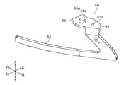
- FIG. 7 is a perspective view showing the right main body 60 of the video display device 1 according to the first embodiment.
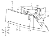
- FIG. 8 is a perspective view showing the right support 5 of the video display device according to the first embodiment.
- FIG. 8 shows a state in which the right support 5 is attached to the lower right side of the display unit 3 and the display unit 3 is erected.
- illustration is abbreviate
- the right side light transmitting portion 50 includes a plate portion 51 and a light transmitting portion support piece 55.
- the plate portion 51 has a long plate shape that is curved so as to warp from the front toward the left rear.
- the peripheral edge portion of the plate portion 51 is subjected to an etching process for expanding the light to be irradiated.
- the plate portion 51 is a light-transmitting resin such as polycarbonate or acrylic, but may be formed of any other material.
- the plate portion 51 has a contact surface 51a, a recess 51b, and a foot side engagement portion 51c.
- the abutting surface 51a is a left side surface (a surface on the display unit 3 side), and a surface that abuts on the emission surface 43a of the right light guide 41. Light that passes through the right light guide 41 enters the contact surface 51a. It is preferable that there is no gap between the contact surface 51a and the emission surface 43a.
- the recess 51b becomes narrower from the surface (right surface) opposite to the contact surface 51a toward the contact surface 51a, and is recessed in the vertical direction.
- the recess 51b has an inclined surface 52k.
- the inclined surface 52k is a side surface of the recess 51b, and is arranged so that the extended surface of the inclined surface 52k and the extended surface of the emission surface 43a intersect each other.
- the foot-side engagement portion 51c is recessed in a shape that allows the right-side main body portion 60 to be fitted from a surface (right-side surface) opposite to the contact surface 51a.
- the foot side engaging part 51c is formed in a substantially L shape so as to follow the lower side of the lower end of the plate part 51 and the rear side of the rear end.
- the translucent portion support piece 55 is bent vertically toward the left side on the rear side of the plate portion 51.
- the translucent portion support piece 55 has a screw hole 55 a and is fixed by a screw that passes through the screw hole 55 a and the right main body portion 60.
- the right main body 60 has an engaging portion 61, a first main body support piece 65, and a second main body support piece 66.
- the engaging portion 61 is a plate having an approximately L shape when viewed in the right direction.
- the engaging portion 61 is fitted into the foot side engaging portion 51 c of the right side light transmitting portion 50 so as to follow the lower side and the rear side of the plate portion 51 in the right side light transmitting portion 50.
- An anti-slip member 81 shown in FIG. 2 made of rubber or the like is provided on the lower end surface of the engaging portion 61.
- the first body support piece 65 is bent vertically toward the left side on the upper side of the engaging portion 61.
- the first main body support piece 65 is located between the cover member 27 and the translucent part support piece 55 of the right translucent part 50.
- the first main body support piece 65 has a screw hole 65a, and the translucent part support piece 55 of the right translucent part 50 is fixed by a screw that passes through each screw hole 65a. That is, the back surface of the right body part 60 is disposed so as to be in close contact with the foot side engaging part 51 c and the first body part support piece 65 in the right light transmitting part 50.
- the second body support piece 66 is flush with the first body support piece 65 and extends forward from the first body support piece 65.
- the second main body support piece 66 has a screw hole 66a, is disposed on the back surface of the second fixing portion 22b of the second right connecting bracket 22, and is fixed to the second fixing portion 22b with screws.
- the second body support piece 66 is accommodated in the accommodation space 25c of the right end cover body 25 so that the right support part 5 cannot be viewed from the outside when assembled to the display unit 3.
- An example is formed in the vertical direction and the front-rear direction with the right light guide 41, the right end cover body 25, the second right connection fitting 22, the right translucent part 50 of the right support part 5, and the right main body part 60 of the right support part 5. Since the configuration is symmetric with respect to the surface to be formed, these descriptions are omitted.
- an upper second light source 33 an example of a second light source
- a lower second light source 34 an example of a second light source
- a left second light source 35 An example of the second light source
- a right second light source 36 an example of the second light source
- the upper second light source 33 is provided near the center of the upper side on the back surface of the panel body 9.
- the lower second light source 34 is provided near the center of the lower side of the back surface of the panel body 9.
- the right second light source 36 is provided near the center of the right side of the back surface of the panel body 9.
- the left second light source 35 is provided near the center of the left side of the back surface of the panel body 9.
- FIG. 9A is a perspective view showing the mounting bracket 82 and the upper second light source 33 of the video display device 1 according to the first embodiment.
- FIG. 9B is a perspective view showing the mounting bracket 82 and the lower second light source 34 of the video display device 1 according to the first embodiment.
- FIG. 9C is a perspective view showing the mounting bracket 82 and the left second light source 35 of the video display device 1 according to the first embodiment.
- the two light sources 36 are attached to the rear surfaces of the corresponding fittings 82 so that light can be emitted toward the rear.
- the upper second light source 33, the lower second light source 34, the left second light source 35, and the right second light source 36 in FIG. 2 are the same optical elements as the right first light source 31 and the left first light source 32.
- the upper second light source 33, the lower second light source 34, the left second light source 35, and the right second light source 36 of FIG. Each is attached to the left back by screws.
- a control circuit for causing the display panel 13 to shine is provided on the back surface of the panel body 9 on the back surface of the mounting bracket 82 to which the lower second light source 34 is attached.
- the control circuit is covered with a mounting bracket 82 to which the lower second light source 34 is attached.
- the right second light source 36 has a symmetrical configuration with respect to the left second light source 35 and a plane formed in the vertical direction and the front-rear direction, and thus description thereof is omitted.
- the rear cabinet 11 is a flat resin cover.
- through holes 11a, 11a, 11a, and 11a are formed at positions corresponding to the upper second light source 33, the lower second light source 34, the left second light source 35, and the right second light source 36, respectively.
- the through hole 11a is a hole penetrating in the front-rear direction.
- the opening behind each through-hole 11a is covered with a diffusion plate 91, respectively.
- FIG. 10A is a partially exploded cross-sectional perspective view showing an upper side portion of the rear cabinet 11 of the video display device 1 according to Embodiment 1.
- FIG. 10B is a perspective view of the diffusion plate 91 of the video display device 1 according to the first embodiment.
- the through hole 11a is formed so that the light emitted from the upper second light source 33 can be guided to the diffusion plate 91 in the through hole 11a.
- the through hole 11a tapers from the rear to the front. In other words, the closer to the upper second light source 33 from the diffusion plate 91, the narrower it becomes. In addition, when seeing the through-hole 11a toward the front, it is preferable that it narrows toward the front from the back so that each board
- a detachable diffusion plate 91 is attached to the rear opening in the through hole 11a in the upper portion of the rear cabinet 11.
- the diffusion plate 91 may be a translucent member. Further, the diffusion plate 91 may be, for example, a diffusion plate in which diffusion particles are provided.
- the diffusing plate 91 has a flat plate portion 91a and a pair of claw portions 91b protruding forward at both ends of the flat plate portion 91a.
- the flat plate portion 91a is formed with an incident convex portion 92 that protrudes forward from the rear surface.
- the incident convex portion 92 is formed in a mountain shape extending vertically.
- a front end side of the incident convex portion 92 is formed with a notch groove 92a extending in the vertical direction and recessed toward the rear.
- the light emitted from the upper second light source 33 enters the notch groove 92a.
- Both the claw portions 91 b are inserted into the engagement holes 11 b shown in FIG. 10B formed in the rear cabinet 11 to fix the diffusion plate 91 to the rear cabinet 11.
- the through holes 11 a, 11 a, 11 a and the diffusion plates 91, 91, 91 corresponding to the lower second light source 34, the left second light source 35, and the right second light source 36 are also referred to as the upper second light source 33.
- the configuration is the same as that of the corresponding through hole 11a and diffusion plate 91, and the description thereof is omitted.
- FIG. 11 is a partial enlarged cross-sectional perspective view showing the rear cabinet 11 of the video display device 1 according to the first embodiment.
- FIG. 11 shows a state in which the rear cabinet 11 is assembled to the panel body 9 and the diffusion plate 91 is assembled to the rear cabinet 11.
- the diffusion plate 91 is arranged so that the light emitted from the upper second light source 33 can be emitted to the outside.
- the diffusion plate 91 has a plurality of diffusion grooves 91c for emitting light to the outside.
- the diffusion groove 91c is an uneven surface formed on the rear surface of the diffusion plate 91 so as to emit light from the upper second light source 33 in the left-right direction on the back side of the display unit 3.
- a plurality of diffusion grooves 91 c extending in the vertical direction are formed in the diffusion plate 91 at a position (upper side) corresponding to the upper second light source 33.
- the diffusion groove 91c has a triangular wave shape in which a peak and a valley are repeated.
- the light emitted from the upper second light source 33 passes through the through hole 11 a and enters from the front surface of the diffusion plate 91.
- the light transmitted through the diffusion plate 91 is emitted so as to spread from the diffusion plate 91.
- the diffusion plate 91 located at the position (lower side) corresponding to the lower second light source 34 also has a diffusion groove extending in the vertical direction similar to the diffusion plate 91 located at the position (upper side) corresponding to the upper second light source 33. A plurality are formed.
- the diffusion plate 91 located at a position (lower side) corresponding to the lower second light source 34 is formed so as to emit light from the lower second light source 34 in the left-right direction on the back side of the display unit 3.
- a plurality of diffusion grooves extending in the left-right direction are formed in the diffusion plate 91 at the position corresponding to the left second light source 35 (left side) and the diffusion plate 91 at the position corresponding to the right second light source 36 (right side). ing.
- the diffusion plate 91 located at the position corresponding to the left second light source 35 (left side) and the diffusion plate 91 located at the position corresponding to the right second light source 36 (right side) are separated from the left second light source 35 and the right second light source 36. Are emitted so as to spread in the vertical direction on the back side of the display unit 3.
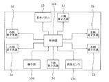
- FIG. 12 is a block diagram showing the video display device 1 according to the first embodiment.
- the panel main body 9 has a control unit 10a and an operation unit 10b in addition to the display panel 13.
- the control unit 10a controls the display panel 13, the backlight, and the like based on a video signal acquired from the outside via a communication unit (not shown).
- the control unit 10a includes, for example, a storage unit (not shown) that stores a control program and an arithmetic processing unit (not shown) that executes the control program.
- the video signal is a signal for displaying an image on the display panel 13, and is output from a recording medium such as a DVD (Digital Versatile Disc) or a broadcasting device such as terrestrial digital broadcasting or satellite digital broadcasting.
- the controller 10a is electrically connected to the right first light source 31, the left first light source 32, the upper second light source 33, the lower second light source 34, the left second light source 35, and the right second light source 36.
- the control unit 10a outputs control signals to the right first light source 31, the left first light source 32, the upper second light source 33, the lower second light source 34, the left second light source 35, and the right second light source 36, and these light sources. Switches the light emitted by the camera to daylight white or light bulb color.
- the control unit 10a includes a switching unit configured with a circuit board and various electronic components mounted on the circuit board.
- the color temperature of daylight white is from 6020K to 7050K
- the color temperature of the light bulb color is from 2580K to 2870K.
- the switching unit allows the user to change the right first light source 31, left first light source 32, upper second light source 33, lower second light source 34, left second light source 35, and right second light source 36 to neutral white or light bulb color. It may be a switch or the like for switching to.
- the right first light source 31 the left first light source 32, the upper second light source 33, the lower second light source 34, the left second light source 35, and the right second light source 36 are in harmony with the surroundings. It is preferable that all of these light sources are unified into a neutral white color or a light bulb color.
- the control unit 10a simultaneously turns on the first light sources that are the right first light source 31 and the left first light source 32, and the upper second light source 33, the lower second light source 34, the left second light source 35, and the right second light source.
- the second light sources 36 are turned on simultaneously. Note that the control unit 10a may be able to turn on and off the light to be lit and irradiated with the first light source and the second light source independently from daylight white or light bulb color.
- FIG. 13 is a schematic diagram showing light transmitted through the right light guide 41 and the right light transmitting unit 50 in the video display device 1 according to the first embodiment.
- the light emitted from the right first light source 31 enters the incident surface 42 a of the right light guide 41.
- Light that is transmitted through the incident surface 42a is reflected by the first reflecting surface 42b of the right light guide 41, is reflected by the second reflecting surface 42c of the right light guide 41, and is reflected by the third reflecting surface 43b shown in FIG. And is emitted from the emission surface 43 a of the insertion portion 43.
- the light emitted from the emission surface 43 a is incident from the contact surface 51 a of the right side light transmitting portion 50.
- the light emitted from the left first light source 32 is the same as that on the right side, and the description thereof is omitted.
- FIG. 14 shows the right first light source 31, the left first light source 32, the upper second light source 33, the lower second light source 34, the left second light source 35, and the right second light source 36 of the video display device according to the first embodiment. It is a schematic diagram which shows the state which turned on.
- the lower side of the video display device 1 becomes brighter due to light irradiation from each first light source. Further, in the video display device 1, the periphery of the display unit 3 is brightly illuminated by irradiating light from the four sides on the rear side of the display unit 3 by irradiating light from each second light source.
- At least one display unit 3 that displays video and at least a portion that is translucent and supports the display unit 3 in an upright state.
- a support part and at least 1 1st light source which is provided in the display unit 3 and irradiates light to at least one part of a support part are provided.
- the lower side of the display unit 3 is brightly illuminated.
- the right support portion 5 and the left support portion 7 include the right translucent portion 50 having translucency and the right side made of metal that engages with the right translucent portion 50.
- a main body 60 A main body 60.
- the right-side main body 60 is engaged with the right-side light-transmitting portion 50, so that the strength of the right-side support portion 5 can be ensured. In addition, the same effect is obtained on the left side.
- the video display device 1 further includes a right light guide 41 that transmits the light emitted from the right first light source 31 to the right light transmitting portion 50.
- the light emitted from the right first light source 31 can be guided to the right translucent part 50 by the right light guide 41, so that the degree of freedom in arranging the right first light source 31 is improved. Note that the same effect is obtained on the left side.
- the video display device 1 further includes a plurality of upper second light sources 33, lower second light sources 34, left second light sources 35, and right second ones arranged along the outer periphery of the display unit 3.
- the light emitted from the diffusing plate 91 is wrapped in soft light having a wide light distribution characteristic by the outer periphery of the display unit 3, so that a harmonious effect with the surroundings in the living space can be performed. it can.
- the video display device 1 further includes the right first light source 31, the left first light source 32, the upper second light source 33, the lower second light source 34, the left second light source 35, and the second right light source.
- the control part 10a which outputs a control signal to the light source 36 is provided.
- the control unit 10a uses a white light or a light bulb as light emitted from the right first light source 31, the left first light source 32, the upper second light source 33, the lower second light source 34, the left second light source 35, and the right second light source 36. Switch to color.
- control unit 10a is irradiated from the right first light source 31, the left first light source 32, the upper second light source 33, the lower second light source 34, the left second light source 35, and the right second light source 36. Since light can be switched to daylight white or light bulb color, it becomes easy to achieve harmony with the surroundings in the living space.
- the display unit 3 is formed with a plurality of through holes 11a that guide the respective lights irradiated from the respective second light sources to the respective diffusion plates 91. And the through-hole 11a is so narrow that it approaches each 2nd light source from each diffusion plate 91. As shown in FIG.
- each second light source is easily emitted from each diffusion plate 91.
- the internal structure of the video display device 1 becomes difficult to see, and the video display device 1 looks good.
- FIG. 15 is a block diagram showing the video display device 1 according to the second embodiment.
- the panel body 9 includes a control unit 10 a, an illuminance sensor 10 c (an example of a sensor unit), and an operation unit 10 b in addition to the display panel 13.
- An illuminance sensor 10c is connected to the control unit 10a.
- the illuminance sensor 10c is a detection circuit that measures ambient illuminance (brightness) and transmits it to the control unit 10a.
- the illuminance sensor 10c is provided so that ambient light can be taken in on the front cabinet 15 side.
- the control unit 10a performs control so that light is emitted from at least one of the first light sources and the second light sources when the illuminance detected by the illuminance sensor 10c is less than a predetermined threshold.
- the control unit 10a when the illuminance detected by the illuminance sensor 10c is equal to or greater than a predetermined threshold, the control unit 10a, the right first light source 31, the left first light source 32, the upper second light source 33, the lower second light source 34, the left second light source 34, Control is performed to stop the irradiation of the two light sources 35 and the right second light source 36.
- the control unit 10a is configured to set the right first light source 31, the left first light source 32, the upper second light source 33, the lower second light source 34, and the left second light source 35 based on preset threshold values stored in the storage unit. And on / off of the second light source 36 on the right side.
- the threshold value may be a preset value or may be arbitrarily set by the user.
- the operation unit 10b receives an operation according to a request from the user.
- the operation unit 10b is, for example, an operation panel built in the video display device 1. Further, the operation unit 10b may be a remote control independent of the video display device 1.
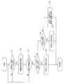
- FIG. 16 is a flowchart showing the operation of the video display apparatus 1 according to the second embodiment.
- the user automatically activates an automatic on / off mode in which each first light source and each second light source is automatically turned on when the outside is dark.
- the automatic on / off mode is an operation mode provided in the input unit of the video display device 1.
- the remote control for operating the video display device 1 is also provided with this automatic light on / off mode. Then, when the user makes settings via the operation unit 10b, the automatic light on / off mode starts.
- the control unit 10a determines whether or not the automatic light on / off mode is set (S1).
- the illuminance sensor 10c measures ambient illuminance (S2).
- the illuminance sensor 10c transmits an illuminance signal indicating the measured illuminance to the control unit 10a.
- the automatic light on / off mode is not set (NO in S1), it is determined that it is not necessary to light each first light source and each second light source, and the process returns to step S1.
- the control unit 10a determines whether or not the ambient illuminance is less than the threshold value from the illuminance signal (S3). When the illuminance is equal to or greater than the predetermined threshold (NO in S3), the control unit 10a determines that the surroundings are bright and does not need to be turned on, and the process returns to step S1.
- the control unit 10a determines that at least one of the first light sources and the second light sources needs to be lit because the surroundings are dark.
- the controller 10a determines whether at least one of each first light source and each second light source is turned on. First, the control unit 10a determines whether or not only the first light source is set to be turned on (S4). When the setting for lighting only each first light source is made (YES in S4), the control unit 10a lights only each first light source (S5). Then go back to the start.
- the control unit 10a determines whether or not the setting for turning on only each second light source is made (S6). When the setting is made to turn on only each second light source (YES in S6), the control unit 10a turns on only each second light source (S7). Then go back to the start.
- control unit 10a determines that both the first light source and each second light source are set to turn on, Both each 1st light source and each 2nd light source are lighted (S8). Then go back to the start.
- the video display device 1 when the user activates the automatic on / off mode, the video display device 1 becomes bright around the video display device 1 when the surroundings are dark (the ambient illuminance is less than the threshold), and the user illuminates the room.
- the first light source and the second light source are turned off by the automatic turn-off / light-off mode.
- this video display device 1 it is possible to make a setting so that the right first light source 31 and the left first light source 32 are not turned on depending on the use situation.
- the user can activate the video display device 1 and select whether to hang or place the video display device 1 at the initial setting.
- the control unit 10a determines that the right support unit 5 and the left support unit 7 are not attached, and sets so that the right first light source 31 and the left first light source 32 do not emit light.
- the control unit 10a determines that the right support unit 5 and the left support unit 7 are attached, and the right first light source 31 and the left first light source 32 are set to emit light. To do.
- the video display device 1 according to Embodiment 2 further includes an illuminance sensor 10c that detects illuminance.
- the control unit 10a further controls to emit light from at least one of the first light source and the second light source when the illuminance detected by the illuminance sensor 10c is less than a predetermined threshold.
- the control part 10a is controlled to stop irradiation of a 1st light source and a 2nd light source, when the illumination intensity detected by the illumination intensity sensor 10c is more than a predetermined threshold value.
- the controller 10a automatically turns on at least one of the first light source and the second light source via the illuminance sensor 10c. Can do. For this reason, the production effect by light irradiation is high.
- the video display device has been described based on the first and second embodiments.
- the present invention is not limited to the first and second embodiments.
- the control unit may perform light emission control according to ambient brightness.
- the storage unit stores a first threshold value and a second threshold value that is larger than the first threshold value.
- the control unit is turned on in neutral white, and when the detected illuminance is greater than or equal to the first threshold value and less than the second threshold value, it is lit in the light bulb color, and the detected illuminance is greater than or equal to the second threshold value In this case, the light may be turned off.
- a reflecting member that reflects light may be provided in addition to each incident surface and each exit surface in the right light guide and the left light guide. In this case, stronger light can be emitted from the emission surface.
- the right first light source and the left first light source may be set so as not to emit light.
- the switch provided in the attachment portion is turned on so that the right first light source and the left first light source can be turned on.
- a mechanism may be employed in which the right first light source and the left first light source cannot be turned on when the right support portion and the left support portion are removed from the attachment portion.
- an optical sensor or the like may be provided in the display unit, and the control unit may determine whether or not to turn on the right first light source and the left first light source based on detection of the sensor.
- the present invention is useful for a video display device such as a television for displaying video.
Landscapes
- Engineering & Computer Science (AREA)
- Physics & Mathematics (AREA)
- General Physics & Mathematics (AREA)
- General Engineering & Computer Science (AREA)
- Optics & Photonics (AREA)
- Multimedia (AREA)
- Theoretical Computer Science (AREA)
- Mechanical Engineering (AREA)
- Signal Processing (AREA)
- Computer Hardware Design (AREA)
- Devices For Indicating Variable Information By Combining Individual Elements (AREA)
- Planar Illumination Modules (AREA)
- Liquid Crystal (AREA)
Abstract
L'invention concerne un dispositif d'affichage d'image (1) qui est pourvu : d'une unité d'affichage (3) qui affiche une image; d'une partie de support côté droit (5) et d'une partie de support côté gauche (7), une de ces parties ayant des propriétés de transmission de lumière, qui portent l'unité d'affichage (3) dans un état vertical; d'une première source de lumière côté droit (31) et d'une première source de lumière côté gauche (32) qui sont disposées sur le dispositif d'affichage (3), et qui émettent de la lumière vers au moins une partie de la partie de support côté droit (5) et de la partie de support côté gauche (7).
Priority Applications (2)
| Application Number | Priority Date | Filing Date | Title |
|---|---|---|---|
| US16/083,363 US10909908B2 (en) | 2016-03-08 | 2017-03-08 | Image display device |
| EP17763340.1A EP3428905A4 (fr) | 2016-03-08 | 2017-03-08 | Dispositif d'affichage d'image |
Applications Claiming Priority (2)
| Application Number | Priority Date | Filing Date | Title |
|---|---|---|---|
| JP2016044994A JP2020095061A (ja) | 2016-03-08 | 2016-03-08 | 映像表示装置 |
| JP2016-044994 | 2016-03-08 |
Publications (1)
| Publication Number | Publication Date |
|---|---|
| WO2017155000A1 true WO2017155000A1 (fr) | 2017-09-14 |
Family
ID=59789596
Family Applications (1)
| Application Number | Title | Priority Date | Filing Date |
|---|---|---|---|
| PCT/JP2017/009331 Ceased WO2017155000A1 (fr) | 2016-03-08 | 2017-03-08 | Dispositif d'affichage d'image |
Country Status (4)
| Country | Link |
|---|---|
| US (1) | US10909908B2 (fr) |
| EP (1) | EP3428905A4 (fr) |
| JP (1) | JP2020095061A (fr) |
| WO (1) | WO2017155000A1 (fr) |
Cited By (1)
| Publication number | Priority date | Publication date | Assignee | Title |
|---|---|---|---|---|
| WO2023189473A1 (fr) * | 2022-03-31 | 2023-10-05 | パナソニックホールディングス株式会社 | Instrument de câblage |
Families Citing this family (5)
| Publication number | Priority date | Publication date | Assignee | Title |
|---|---|---|---|---|
| CN208239763U (zh) * | 2018-04-02 | 2018-12-14 | 京东方科技集团股份有限公司 | 背光模块和液晶显示装置 |
| USD908797S1 (en) * | 2018-12-14 | 2021-01-26 | Lg Electronics Inc. | Monitor for digital signage |
| WO2023182544A1 (fr) * | 2022-03-23 | 2023-09-28 | 엘지전자 주식회사 | Dispositif d'affichage |
| KR20250056744A (ko) * | 2023-10-19 | 2025-04-28 | 삼성전자주식회사 | 디스플레이 장치 |
| WO2025141692A1 (fr) * | 2023-12-26 | 2025-07-03 | パイオニア株式会社 | Dispositif d'affichage |
Citations (6)
| Publication number | Priority date | Publication date | Assignee | Title |
|---|---|---|---|---|
| JP2000276940A (ja) * | 1999-03-27 | 2000-10-06 | Tsutomu Odawara | 暗やみの中での電光画面に付随する間接照明 |
| JP2002132378A (ja) * | 2000-10-17 | 2002-05-10 | Internatl Business Mach Corp <Ibm> | 表示装置、液晶表示装置、電子機器およびコンピュータ装置 |
| JP2005012616A (ja) * | 2003-06-20 | 2005-01-13 | Funai Electric Co Ltd | 液晶テレビジョン用台座 |
| JP2006259667A (ja) * | 2005-03-18 | 2006-09-28 | Samsung Sdi Co Ltd | 周辺に間接照明を照らすディスプレイ装置 |
| JP2011215420A (ja) * | 2010-03-31 | 2011-10-27 | Toshiba Corp | 表示装置 |
| US20150029752A1 (en) * | 2013-07-24 | 2015-01-29 | Young Lighting Technology Inc. | Display device |
Family Cites Families (9)
| Publication number | Priority date | Publication date | Assignee | Title |
|---|---|---|---|---|
| JP3615355B2 (ja) * | 1997-06-04 | 2005-02-02 | 株式会社エンプラス | サイドライト型面光源装置及び導光板 |
| US20090167192A1 (en) * | 2004-06-30 | 2009-07-02 | Koninklijke Philips Electronics, N.V. | Active frame system for ambient lighting using a video display as a signal source |
| RU2444151C2 (ru) * | 2007-01-03 | 2012-02-27 | Конинклейке Филипс Электроникс Н.В. | Отображающая компоновка ambilight |
| US20090045723A1 (en) * | 2007-08-15 | 2009-02-19 | Motorola, Inc. | Apparatus and method for synchronizing illumination around an organic light emitting display |
| TWI368087B (en) * | 2008-10-27 | 2012-07-11 | Coretronic Corp | Backlight module and liquid crystal display |
| US8698065B2 (en) * | 2009-03-05 | 2014-04-15 | Wintek Corporation | Photo sensing module having protection function and display device |
| US20100289942A1 (en) | 2009-05-18 | 2010-11-18 | Sony Corporation And Sony Electronics | Feedback system for optimizing exposure |
| JP2012220755A (ja) * | 2011-04-11 | 2012-11-12 | Funai Electric Co Ltd | 液晶表示装置および液晶モジュール |
| EP2775333A1 (fr) | 2013-03-07 | 2014-09-10 | TP Vision Holding B.V. | Dispositif électronique avec guide de lumière partagé |
-
2016
- 2016-03-08 JP JP2016044994A patent/JP2020095061A/ja active Pending
-
2017
- 2017-03-08 WO PCT/JP2017/009331 patent/WO2017155000A1/fr not_active Ceased
- 2017-03-08 US US16/083,363 patent/US10909908B2/en active Active
- 2017-03-08 EP EP17763340.1A patent/EP3428905A4/fr not_active Ceased
Patent Citations (6)
| Publication number | Priority date | Publication date | Assignee | Title |
|---|---|---|---|---|
| JP2000276940A (ja) * | 1999-03-27 | 2000-10-06 | Tsutomu Odawara | 暗やみの中での電光画面に付随する間接照明 |
| JP2002132378A (ja) * | 2000-10-17 | 2002-05-10 | Internatl Business Mach Corp <Ibm> | 表示装置、液晶表示装置、電子機器およびコンピュータ装置 |
| JP2005012616A (ja) * | 2003-06-20 | 2005-01-13 | Funai Electric Co Ltd | 液晶テレビジョン用台座 |
| JP2006259667A (ja) * | 2005-03-18 | 2006-09-28 | Samsung Sdi Co Ltd | 周辺に間接照明を照らすディスプレイ装置 |
| JP2011215420A (ja) * | 2010-03-31 | 2011-10-27 | Toshiba Corp | 表示装置 |
| US20150029752A1 (en) * | 2013-07-24 | 2015-01-29 | Young Lighting Technology Inc. | Display device |
Cited By (3)
| Publication number | Priority date | Publication date | Assignee | Title |
|---|---|---|---|---|
| WO2023189473A1 (fr) * | 2022-03-31 | 2023-10-05 | パナソニックホールディングス株式会社 | Instrument de câblage |
| JP2023151538A (ja) * | 2022-03-31 | 2023-10-16 | パナソニックホールディングス株式会社 | 配線器具 |
| JP7804515B2 (ja) | 2022-03-31 | 2026-01-22 | パナソニックホールディングス株式会社 | 配線器具 |
Also Published As
| Publication number | Publication date |
|---|---|
| EP3428905A1 (fr) | 2019-01-16 |
| JP2020095061A (ja) | 2020-06-18 |
| US10909908B2 (en) | 2021-02-02 |
| EP3428905A4 (fr) | 2019-02-20 |
| US20190103051A1 (en) | 2019-04-04 |
Similar Documents
| Publication | Publication Date | Title |
|---|---|---|
| WO2017155000A1 (fr) | Dispositif d'affichage d'image | |
| CN207198370U (zh) | 照明装置 | |
| WO2007020720A1 (fr) | Dispositif de commande d’une source de lumière, dispositif d’éclairage et dispositif d’affichage à cristaux liquides | |
| CN107606574A (zh) | 照明装置 | |
| JP4883522B2 (ja) | 液晶表示装置及びそれに用いるバックライトユニット | |
| JP2018170132A (ja) | 照明装置および照明システム | |
| JP6065697B2 (ja) | 車両用照明装置、及び車両用照明システム | |
| EP2202547B1 (fr) | Dispositif d'affichage | |
| JP2011096639A (ja) | バックライトタッチボタン | |
| KR101053599B1 (ko) | 발광 로고 어셈블리 | |
| JP6872720B2 (ja) | 照明装置 | |
| JP6820524B2 (ja) | 照明装置 | |
| JP3910563B2 (ja) | Led式歩行者用信号灯器 | |
| KR20160089802A (ko) | 엘이디 복합 조명장치 | |
| US10295381B2 (en) | Indicator | |
| JP2023052594A (ja) | 照明器具 | |
| JP3536773B2 (ja) | 表示パネル | |
| TWI557369B (zh) | 照明用罩以及照明裝置 | |
| CN114270425B (zh) | 图像显示装置及其控制方法 | |
| CN219550355U (zh) | 照明灯和车辆 | |
| JP5678786B2 (ja) | 照明装置 | |
| JP7070027B2 (ja) | 表示装置 | |
| JP2010205486A (ja) | 鏡面装置及びこの鏡面装置を用いた照明装置 | |
| JP2023048402A (ja) | 照明ランプ及び照明器具 | |
| JP2014081402A (ja) | 電子機器、イルミネーション装置 |
Legal Events
| Date | Code | Title | Description |
|---|---|---|---|
| NENP | Non-entry into the national phase |
Ref country code: DE |
|
| WWE | Wipo information: entry into national phase |
Ref document number: 2017763340 Country of ref document: EP |
|
| ENP | Entry into the national phase |
Ref document number: 2017763340 Country of ref document: EP Effective date: 20181008 |
|
| 121 | Ep: the epo has been informed by wipo that ep was designated in this application |
Ref document number: 17763340 Country of ref document: EP Kind code of ref document: A1 |