WO2017155113A1 - レトルト密着性に優れるフィルムラミネート金属板およびその製造方法 - Google Patents
レトルト密着性に優れるフィルムラミネート金属板およびその製造方法 Download PDFInfo
- Publication number
- WO2017155113A1 WO2017155113A1 PCT/JP2017/009804 JP2017009804W WO2017155113A1 WO 2017155113 A1 WO2017155113 A1 WO 2017155113A1 JP 2017009804 W JP2017009804 W JP 2017009804W WO 2017155113 A1 WO2017155113 A1 WO 2017155113A1
- Authority
- WO
- WIPO (PCT)
- Prior art keywords
- film
- metal plate
- resin film
- roll
- retort
- Prior art date
- Legal status (The legal status is an assumption and is not a legal conclusion. Google has not performed a legal analysis and makes no representation as to the accuracy of the status listed.)
- Ceased
Links
Images




Classifications
-
- B—PERFORMING OPERATIONS; TRANSPORTING
- B32—LAYERED PRODUCTS
- B32B—LAYERED PRODUCTS, i.e. PRODUCTS BUILT-UP OF STRATA OF FLAT OR NON-FLAT, e.g. CELLULAR OR HONEYCOMB, FORM
- B32B37/00—Methods or apparatus for laminating, e.g. by curing or by ultrasonic bonding
- B32B37/08—Methods or apparatus for laminating, e.g. by curing or by ultrasonic bonding characterised by the cooling method
-
- B—PERFORMING OPERATIONS; TRANSPORTING
- B29—WORKING OF PLASTICS; WORKING OF SUBSTANCES IN A PLASTIC STATE IN GENERAL
- B29C—SHAPING OR JOINING OF PLASTICS; SHAPING OF MATERIAL IN A PLASTIC STATE, NOT OTHERWISE PROVIDED FOR; AFTER-TREATMENT OF THE SHAPED PRODUCTS, e.g. REPAIRING
- B29C65/00—Joining or sealing of preformed parts, e.g. welding of plastics materials; Apparatus therefor
- B29C65/02—Joining or sealing of preformed parts, e.g. welding of plastics materials; Apparatus therefor by heating, with or without pressure
- B29C65/44—Joining a heated non plastics element to a plastics element
-
- B—PERFORMING OPERATIONS; TRANSPORTING
- B32—LAYERED PRODUCTS
- B32B—LAYERED PRODUCTS, i.e. PRODUCTS BUILT-UP OF STRATA OF FLAT OR NON-FLAT, e.g. CELLULAR OR HONEYCOMB, FORM
- B32B15/00—Layered products comprising a layer of metal
- B32B15/04—Layered products comprising a layer of metal comprising metal as the main or only constituent of a layer, which is next to another layer of the same or of a different material
- B32B15/08—Layered products comprising a layer of metal comprising metal as the main or only constituent of a layer, which is next to another layer of the same or of a different material of synthetic resin
-
- B—PERFORMING OPERATIONS; TRANSPORTING
- B32—LAYERED PRODUCTS
- B32B—LAYERED PRODUCTS, i.e. PRODUCTS BUILT-UP OF STRATA OF FLAT OR NON-FLAT, e.g. CELLULAR OR HONEYCOMB, FORM
- B32B15/00—Layered products comprising a layer of metal
- B32B15/04—Layered products comprising a layer of metal comprising metal as the main or only constituent of a layer, which is next to another layer of the same or of a different material
- B32B15/08—Layered products comprising a layer of metal comprising metal as the main or only constituent of a layer, which is next to another layer of the same or of a different material of synthetic resin
- B32B15/09—Layered products comprising a layer of metal comprising metal as the main or only constituent of a layer, which is next to another layer of the same or of a different material of synthetic resin comprising polyesters
-
- B—PERFORMING OPERATIONS; TRANSPORTING
- B32—LAYERED PRODUCTS
- B32B—LAYERED PRODUCTS, i.e. PRODUCTS BUILT-UP OF STRATA OF FLAT OR NON-FLAT, e.g. CELLULAR OR HONEYCOMB, FORM
- B32B37/00—Methods or apparatus for laminating, e.g. by curing or by ultrasonic bonding
- B32B37/0007—Methods or apparatus for laminating, e.g. by curing or by ultrasonic bonding involving treatment or provisions in order to avoid deformation or air inclusion, e.g. to improve surface quality
-
- B—PERFORMING OPERATIONS; TRANSPORTING
- B32—LAYERED PRODUCTS
- B32B—LAYERED PRODUCTS, i.e. PRODUCTS BUILT-UP OF STRATA OF FLAT OR NON-FLAT, e.g. CELLULAR OR HONEYCOMB, FORM
- B32B37/00—Methods or apparatus for laminating, e.g. by curing or by ultrasonic bonding
- B32B37/06—Methods or apparatus for laminating, e.g. by curing or by ultrasonic bonding characterised by the heating method
-
- B—PERFORMING OPERATIONS; TRANSPORTING
- B65—CONVEYING; PACKING; STORING; HANDLING THIN OR FILAMENTARY MATERIAL
- B65B—MACHINES, APPARATUS OR DEVICES FOR, OR METHODS OF, PACKAGING ARTICLES OR MATERIALS; UNPACKING
- B65B55/00—Preserving, protecting or purifying packages or package contents in association with packaging
- B65B55/02—Sterilising, e.g. of complete packages
-
- B—PERFORMING OPERATIONS; TRANSPORTING
- B65—CONVEYING; PACKING; STORING; HANDLING THIN OR FILAMENTARY MATERIAL
- B65B—MACHINES, APPARATUS OR DEVICES FOR, OR METHODS OF, PACKAGING ARTICLES OR MATERIALS; UNPACKING
- B65B55/00—Preserving, protecting or purifying packages or package contents in association with packaging
- B65B55/02—Sterilising, e.g. of complete packages
- B65B55/04—Sterilising wrappers or receptacles prior to, or during, packaging
- B65B55/06—Sterilising wrappers or receptacles prior to, or during, packaging by heat
-
- B—PERFORMING OPERATIONS; TRANSPORTING
- B65—CONVEYING; PACKING; STORING; HANDLING THIN OR FILAMENTARY MATERIAL
- B65D—CONTAINERS FOR STORAGE OR TRANSPORT OF ARTICLES OR MATERIALS, e.g. BAGS, BARRELS, BOTTLES, BOXES, CANS, CARTONS, CRATES, DRUMS, JARS, TANKS, HOPPERS, FORWARDING CONTAINERS; ACCESSORIES, CLOSURES, OR FITTINGS THEREFOR; PACKAGING ELEMENTS; PACKAGES
- B65D25/00—Details of other kinds or types of rigid or semi-rigid containers
- B65D25/14—Linings or internal coatings
-
- B—PERFORMING OPERATIONS; TRANSPORTING
- B65—CONVEYING; PACKING; STORING; HANDLING THIN OR FILAMENTARY MATERIAL
- B65D—CONTAINERS FOR STORAGE OR TRANSPORT OF ARTICLES OR MATERIALS, e.g. BAGS, BARRELS, BOTTLES, BOXES, CANS, CARTONS, CRATES, DRUMS, JARS, TANKS, HOPPERS, FORWARDING CONTAINERS; ACCESSORIES, CLOSURES, OR FITTINGS THEREFOR; PACKAGING ELEMENTS; PACKAGES
- B65D65/00—Wrappers or flexible covers; Packaging materials of special type or form
- B65D65/38—Packaging materials of special type or form
- B65D65/40—Applications of laminates for particular packaging purposes
-
- B—PERFORMING OPERATIONS; TRANSPORTING
- B32—LAYERED PRODUCTS
- B32B—LAYERED PRODUCTS, i.e. PRODUCTS BUILT-UP OF STRATA OF FLAT OR NON-FLAT, e.g. CELLULAR OR HONEYCOMB, FORM
- B32B2250/00—Layers arrangement
- B32B2250/02—2 layers
-
- B—PERFORMING OPERATIONS; TRANSPORTING
- B32—LAYERED PRODUCTS
- B32B—LAYERED PRODUCTS, i.e. PRODUCTS BUILT-UP OF STRATA OF FLAT OR NON-FLAT, e.g. CELLULAR OR HONEYCOMB, FORM
- B32B2439/00—Containers; Receptacles
Definitions
- the present invention relates to a film-laminated metal plate for food containers, and in particular, the peeling length of the film is small, and among the bubbles present between the metal plate and the film, the bubbles harmful to the can characteristics after canning are reduced.
- the present invention relates to a film-laminated metal plate effective for manufacturing and a method for producing the same.
- steel plate cans based on steel plates that do not use Sn are widely used for food containers, but in recent years, bisphenol A (hereinafter referred to as the raw material of paint) Since BPA) is an environmental hormone substance, its use tends to be refrained, and paint manufacturers are developing BPA-free type paints for cans.
- BPA-free paints are less corrosive than conventional BPA paints because they have a low steel-steel adhesion, so it is difficult to say that they have sufficient corrosion resistance for all the contents of current paint cans. It is difficult to apply to strong contents.
- the film laminated steel sheet which has been applied mainly to beverage cans, uses polyester film, there is no problem with BPA, and in recent years it has also been applied to food cans. It is attracting attention as a container material.
- Film laminated metal plates are generally produced by heat-bonding a film with a hard rubber roll on both sides of a heated metal plate, and the film heat-sealed to the metal plate is firmly attached to the metal plate.
- the film is pressure-bonded with a rubber roll while passing a heated metal plate at a high speed, there is a drawback that air bubbles are easily involved along the unevenness of the metal plate.
- the food container is retorted to sterilize it.
- high-pressure steam permeates the film during retort treatment and accumulates in the bubble portion, thereby reducing the adhesion of the film.
- retort the adhesion after retorting of the film
- Patent Document 1 discloses that when a sheet made of a resin film and / or a metal foil or a pre-laminated body thereof is laminated on a steel strip, A method for preventing air entrainment at the time of manufacturing a laminated steel sheet is shown, wherein the sheet is fed toward the steel strip while maintaining an angle between the sheet and the steel strip at 30 to 90 degrees. .
- Patent Document 1 air entrainment when the steel strip and the resin film are pressure-bonded can be reduced, but when the resin film is pressure-bonded and laminated to the steel strip, some air bubbles enter between the steel strip and the resin film. Since air bubbles remaining between the steel strip and the resin film are not unavoidable, they are not discharged in the subsequent plate passing process. Therefore, the manufacturing method shown in Patent Document 1 only removes the air bubbles between the steel strip and the resin film. It was difficult.
- Patent Document 2 shows that by laminating a film on a metal strip under reduced pressure, it is possible to reduce bubble entrainment between the steel sheet and the film.
- the space located on the upstream side of the pressure roll is depressurized, air is easily sucked between the laminate roll and the film from the outside of the depressurized space, so it is difficult to avoid entrainment of bubbles.
- the pressure is reduced with the air bubbles being entrained, the air bubbles near the end in the width direction of the film are easily removed, so that the adhesion between the laminate roll and the film becomes higher at the end in the width direction of the film.
- the present invention solves the above-mentioned problems, provides a film laminated metal sheet having excellent retort adhesion with few bubbles having a bubble shape harmful to film adhesion, and provides a method for easily producing the product.
- the present inventors diligently studied a method for solving the above problems.
- the film was roll-bonded to a metal plate heated to a temperature higher than the melting point of the film, cooled within 2 seconds, and passed through the laminated metal plate at a temperature not lower than the glass transition temperature (Tg) of the resin film and lower than the crystallization temperature.
- Tg glass transition temperature
- the harmful air bubbles referred to here are air bubbles that are present between the film and the metal plate of the film-laminated metal plate, and have an average height of the top three from the highest of the air bubble heights of more than 5 ⁇ m. It has been found that by reducing the harmful air bubbles, the retort adhesion necessary for a laminated metal plate is improved, and a film laminated metal plate having excellent can characteristics after canning can be obtained.
- a film-laminated metal plate having excellent retort adhesion according to an aspect of the present invention includes a metal plate, a resin film thermally fused to the surface of the metal plate, and the metal plate and the resin film.
- the average of the top three bubbles having the highest bubble height is 0 ⁇ m or more.
- Resin film is the metal Length detached from and is 15mm or less.
- the method for producing a film-laminated metal plate having excellent retort adhesion according to one aspect of the present invention is the method for producing a film-laminated metal plate according to (1) above, and is above the melting point of the resin film.
- the resin film is pressure-bonded to the heated metal plate with a film laminating roll, and within 2.0 seconds after the pressure-bonding, the glass film has a glass transition point temperature Tg or higher and lower than the crystallization temperature Tc. Cool and pass through the temperature range of 20 to 60 N / mm 2 at least 3 times and wound around a roll circumference ratio of 20 to 55% per roll. .
- the threading plate tension may be 40 to 60 N / mm 2 .
- At least one of the rolls around which the film-laminated metal plate is wound has a diameter of 200 to 600 mm. It may be within the range.
- the present invention compared to the conventional manufacturing method, among the bubbles entrained between the metal plate and the film, particularly the retort adhesion, since the bubbles harmful to the can characteristics can be reduced, The film peeling length after the retort treatment is reduced, adhesion is improved, and corrosion caused by bubbles can be greatly reduced. As a result, the application range can be further expanded, particularly as a laminated metal plate for food containers, and the effect is extremely great.
- the film laminate metal plate 10 (film laminate metal plate according to this embodiment) according to an embodiment of the present invention will be described.
- the resin film 5 on the inner side of the container at least when processed into a container has a weight of 100 g suspended on one side of a 180 ° film peeling test piece having a width of 30 mm.
- the peeled length of the film after retorting at 125 ° C. for 30 minutes in the state is 15 mm or less, and the bubbles 3 existing between the resin film 5 and the metal plate 1 are obtained from the 3D analysis image of the laser microscope.
- the average of the top three from the highest measured value of the bubble height is 0 ⁇ m or more and 5.0 ⁇ m or less.
- the film laminate metal plate 10 includes a metal plate 1 for laminating a resin film 5.
- the metal plate 1 may be any of a tin-plated steel plate, a tin-free steel plate, a cold-rolled steel plate, a stainless steel plate, an aluminum plate, a titanium plate, and the like, and is not particularly limited. However, from the viewpoint of food hygiene, workability, corrosion resistance, film adhesion, and material price, a tin-plated steel plate or a tin-free steel plate is preferable.
- the thickness of the metal plate 1 is not particularly limited. However, if it is too thin, the workability is lowered, which is not preferable. On the other hand, if it is too thick, it is not economical and the film tends to break at the bent portion. Therefore, from these points, the thickness of the metal plate 1 is preferably 0.12 mm or more and 0.40 mm or less.
- the surface roughness of the metal plate 1 is not particularly limited. However, when the surface roughness of the metal plate 1 is less than 0.05 ⁇ m as the arithmetic average roughness Ra specified in JISB0601, the metal plate 1 and the resin film 5 If the bubbles 3 enter between them, the bubbles 3 are difficult to escape. On the other hand, when the surface roughness of the metal plate 1 exceeds 0.8 ⁇ m in average roughness Ra, when the resin film 5 is pressure-bonded and laminated on the metal plate 1, it is easy to entrain bubbles along the irregularities on the surface of the metal plate 1. Therefore, the surface roughness of the metal plate 1 is preferably 0.05 ⁇ m or more and 0.8 ⁇ m or less in terms of average roughness Ra. More preferably, it is 0.1 ⁇ m or more and 0.6 ⁇ m or less.
- the metal plate 1 may be further subjected to surface treatment on the surface of the metal plate 1 described above.
- Cr, Zr, Al, Si, P, Ti, Ce, W for the purpose of improving the adhesion between the metal plate 1 and the resin film 5 on the surface of the metal plate 1 on the inner surface side of the can product.
- a chemical conversion film (not shown) composed of one or more elements selected from the above, O, and unavoidable components may be formed. Since the chemical conversion film (not shown) made of the above-mentioned hydroxide and oxide of an element has a hydroxyl group, it forms a hydrogen bond with the hydroxyl group of the polyester resin. Therefore, the adhesion between the metal plate 1 and the resin film 5 is improved.
- a method for forming a chemical conversion film (not shown) containing one or more elements selected from Cr, Zr, Al, P, Ti, Ce, and W, fluorides, nitrates, sulfates, chlorides of various elements
- a method of electrolytic treatment in an aqueous solution of acetate, formate, carbonate, or a method using an etching reaction by immersion can be employed.
- water washing or hot water washing after the chemical conversion treatment most of the counter ion species of the above elements are removed from the chemical conversion treatment film (not shown), but a trace amount may remain as an inevitable component.
- the counter ion species as an inevitable component may be present as long as it does not affect the properties of the chemical conversion coating.
- the metal plate 1 may have a film (not shown) formed by a silane coupling agent treatment in addition to the chemical conversion treatment film (not shown).
- a film (not shown) formed by the silane coupling agent treatment is preferable because it contains an Si compound and has excellent adhesion to the metal plate 1 and the resin film 5.
- the film laminate metal plate 10 includes a resin film 5 on the surface of the metal plate 1.
- the resin film 5 is preferably a polyester film because it is excellent in processability, adhesion, corrosion resistance, hygiene, and flavor retention.
- the polyester film may be a stretched film or an unstretched film, and is not particularly limited. However, a stretched film is more preferable because it is superior in corrosion resistance and strength compared to an unstretched film and is less expensive than an unstretched film.
- the resin constituting the polyester film may be, for example, a copolymer polyester mainly comprising an ethylene terephthalate unit and containing an ethylene isophthalate unit or a butylene terephthalate unit as a copolymer component in addition to the ethylene terephthalate unit. It may be a mixture of terephthalate and polyethylene terephthalate / isophthalate copolymer or polyethylene terephthalate / butylene terephthalate copolymer.
- the ethylene isophthalate unit is preferably 12 mol% or less of the entire polyester film.
- the ratio of the polyethylene isophthalate unit in the polyester film exceeds 12 mol%, the crystallinity of the alignment layer is lowered, so that the moisture permeability of the film may increase and the corrosion resistance may decrease.
- the resin film 5 may be a single layer or may have a two-layer or three-layer structure. In the case of a multilayer structure, the resin type of each layer may be different.
- the molecular weight of the polyester resin has a good correlation with the intrinsic viscosity (IV), and the molecular weight is generally managed by the intrinsic viscosity. Therefore, it is preferable that the intrinsic viscosity (IV) is in an appropriate range as a control value corresponding to the molecular weight of the polyester film.
- the intrinsic viscosity (IV) of the polyester film is preferably 0.30 dl / g or more because the strength and elongation of the resin are high.
- the intrinsic viscosity is measured by using a solution in which a resin is dissolved at a concentration of 0.5% in an o-chlorophenol solvent at 25 ° C., and is obtained by the following equation (i).
- Intrinsic viscosity ⁇ ln (t / t0) ⁇ / C (i)
- C represents the concentration expressed in g of resin per 100 ml of the solution
- t0 represents the solvent flow time (unit: second)
- t represents the solution flow time (unit: second).
- the glass transition temperature of the resin film 5 is preferably 50 ° C. or higher and more preferably in the range of 60 ° C. to 90 ° C. from the viewpoint of preventing the oligomer component from eluting into the contents.
- the heat shrinkage rate of the resin film 5 is preferably 15% or less. When the thermal shrinkage rate exceeds 15%, it is not preferable to apply to a can in which a printing body is printed on the can body part after making the can because the film may peel off at the flange part. Further, when the heat shrinkage rate exceeds 15%, it is not preferable to use it for the application of performing retort sterilization treatment at a high temperature because the film adhesion may be lowered and peeled during retort.
- the thickness of the resin film 5 is preferably 8 ⁇ m or more and 30 ⁇ m or less.
- the thickness of the resin film 5 is less than 8 ⁇ m, the corrosion resistance is insufficient depending on the contents, and the resin film 5 may break during processing into a container or the like, which is not preferable.
- the thickness of the resin film 5 exceeds 30 ⁇ m, since the orientation layer thickness is relatively thick compared to the fusion-bonded amorphous layer with the metal plate 1, the shrinkage force after molding and retort treatment becomes strong, Since the resin film 5 may peel off, it is not preferable.
- the elongation of the resin film 5 is preferably 100% or more.
- the surface of the resin film 5 may break at a portion having a small bending radius. Such a crack is not preferable because it becomes a starting point of corrosion on the inner surface side of the lid.
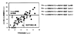
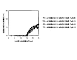
- FIG. 1 shows the influence of the number of times of winding on a pass line transport roll after the resin film 5 is laminated on the metal plate 1 with respect to the relationship between the average bubble height and the post-retort film peeling length.
- the resin film 5 is not less than the glass transition temperature (Tg) and less than the crystallization temperature (Tc) of the film, as described later, without being sandwiched between two pairs of rolls and subjected to reduction.
- Tg glass transition temperature
- Tc crystallization temperature
- the temperature of the metal plate 1 wound around the roll after lamination is higher than the crystallization temperature (Tc) of the resin film 5, in addition to the suppression of air permeation due to the progress of crystallization, the rigidity of the resin film 5 at a high temperature. Therefore, the height of the bubble may be increased due to the expansion of the air in the bubble 3, so that the upper limit temperature of the plate temperature wound around the roll is preferably less than the crystallization temperature (Tc) of the film.
- the lower limit temperature of the plate temperature wound around the roll is preferably equal to or higher than the glass transition temperature (Tg) of the resin film 5.
- the number of windings on the roll is 2 times or less, since the diffusion time of the air in the bubbles 3 is not sufficient as described above, the bubbles having a high bubble height (the average height of the top three from the highest bubble height) Since 3 still exists, the number of windings on the roll is preferably 3 or more.
- the average of the top three bubbles having the highest bubble height is more than 5.0 ⁇ m
- the bubble 3 having a higher bubble height is adjacent, moisture permeates between the bubbles 3 and the resin film 5 and the metal plate Since the adhesiveness after the retort process with 1 is remarkably lowered, it is not preferable.
- the height of the bubbles 3 is high, the risk of causing film defects such as wrinkles due to damage of the convex portions of the bubbles 3 due to sliding with the mold during can making is not preferable.
- the bubble height of the bubbles 3 existing between the resin film 5 and the metal plate 1 is set such that the average height (average bubble height) of the top three from the highest is 0 ⁇ m or more and 5.0 ⁇ m or less. It is preferable to do this. Further, when the mold and the surface of the resin film 5 are slid during can making, the vicinity of the apex of the bubbles 3 is easily damaged, and if the degree of damage of the bubbles 3 is large, film pinholes are easily formed and the corrosion resistance is deteriorated. This is not preferable because it causes. In the above description, the lower limit of the average bubble height is set to 0 ⁇ m or more. However, if it is 2 ⁇ m or more, practically suitable retort adhesion can be obtained. Therefore, the average bubble height may be 2 ⁇ m or more and 5.0 ⁇ m or less.
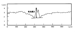
- the reason why the average bubble height affects the post-retort film peeling length is that when bubbles 3 having a large average bubble height are present, as shown in the bubble shape cross-sectional schematic diagram of FIG. Water vapor easily penetrates into the inside of the bubble 3 from the thinned portion of the resin film 5, moisture enters the interface between the resin film 5 and the metal plate 1 around the bubble 3, and the adhesion of the resin film 5 decreases. Therefore, it is estimated that the bubble height is greatly related to the adhesion.
- the measurement of the height of the bubble 3 excludes an error due to the position of the measurement, so that a sample of about 10 mm ⁇ 10 mm at any three locations from the sample of the film laminated metal plate 10 having a width of about 20 cm ⁇ length of about 30 cm.
- the resin film surface of each sample was cut at a magnification of 200 times (field of view: 0.50 mm length x 0.705 mm width) for any 10 fields of view (0.3525 mm 2 per field of view, 10 fields of view total area 3 . 525 mm 2 ) image is taken, the height of the bubble 3 having the highest height in each field of view is measured by the above-described bubble height measurement method, and the height of the bubble is measured for 10 fields of view.
- the bubble height is measured by measuring the profile of the resin film 5 surface of the film-laminated metal plate 10 with a resolution of 0.1 ⁇ m or less using the 3D profile measurement function of the laser microscope, and performing image analysis processing to measure the surface of the bubble 3 It is possible to measure by analyzing the distance from the top of the bubble 3 to the base line by extracting the cross-sectional profile of the bubble 3 and dropping a perpendicular line to the base line drawn from the top of the bubble 3 to both ends of the bubble 3. An outline of the measurement will be described with reference to FIGS. 5A to 5C.
- 5A is an example of an appearance photograph of the bubble 3
- FIG. 5B is an example of a laser microscope 3D profile image of the bubble 3
- FIG. 5C is an example of extracting the cross-sectional profile of the bubble 3 from the laser microscope 3D profile image and analyzing the bubble height.
- FIG. 6 shows a schematic diagram of a method for producing the film laminated metal plate 10.
- the resin film 5 is pressure-bonded by a pair of film laminating rolls 20 on a known metal plate 1 heated by a heating roll (not shown), and the resin film 5 is heat-sealed.
- the method of winding around the rolls is in the width and length directions. This is preferable because a uniform film layer structure can be formed and the number of bubbles 3 entangled between the metal plate 1 and the resin film 5 can be reduced.
- a jacket roll that heats a heating medium such as a plurality of steams through the roll, or a method of heating the metal plate through a heating roll containing a heater is a metal
- the sheet width direction and the length direction are particularly preferable because they can be heated uniformly and stably.
- a rubber roll is preferable because an appropriate nip length can be secured at the film laminating portion.
- rubber having high heat resistance such as fluorine rubber and silicon rubber is particularly preferable.
- the film laminated metal plate 10 is immediately cooled to a temperature lower than the crystallization temperature of the polyester film by a method such as water cooling, air-water cooling, or cold air.
- a method such as water cooling, air-water cooling, or cold air.
- Tg glass transition point temperature
- the resin molecules become difficult to thermally move and the resin becomes hard, and the resin film 5 is laminated on the metal plate 1. In doing so, it is difficult for the bubbles 3 entrained between the metal plate 1 and the resin film 5 to penetrate between the molecules of the resin film 5 and escape, making this undesirable.
- the crystallization of the resin film 5 proceeds to increase the density of the resin film 5, and between the metal plate 1 and the resin film 5. This is not preferable because the bubble 3 that is entrained is difficult to escape. Therefore, the cooling after the resin film 5 is heat-sealed to the metal plate 1 is performed so that the plate temperature is not lower than the glass transition temperature (Tg) of the resin film 5 and lower than the crystallization temperature (Tc) of the resin film 5. It is preferable to hold.
- the time for cooling to a temperature not lower than the glass transition temperature (Tg) and lower than the crystallization temperature (Tc) of the resin film 5 is 2.0 seconds or less. Is preferred.
- the thermally fused molten amorphous phase is Since spherulization starts, the gas diffusion rate of the film layer becomes slow, and the bubbles 3 caught between the metal plate 1 and the resin film 5 are difficult to escape.
- the cooling includes positive cooling using a refrigerant, and cooling if it satisfies 2.0 seconds or less up to a temperature lower than the crystallization temperature (Tc).
- the resin film 5 in order to reduce the bubbles 3, as described above, is held in a temperature range higher than the glass transition temperature (Tg) and lower than the crystallization temperature (Tc) of the film. It is characterized in that it is wound at least three times or more in a roll circumference ratio of 20% or more and 55% or less per roll with respect to the roll through which the film laminate metal plate 10 is passed in the temperature range. And The reason is to apply pressure to the resin film 5 surface of the film laminate metal plate 10, but there is also a method of pressing the film surface by sandwiching the front and back surfaces of the film laminate metal plate 10 with a roll. This is not preferable because the contact time with the metal plate 10 is short and the time required to diffuse the bubbles 3 cannot be obtained.
- the number of windings is also not preferable from the tension specifications of the existing laminated metal plate manufacturing equipment, because it is difficult to apply a higher tension than necessary to the film laminated metal plate 10 by one winding, or considerable equipment modification is required.
- the method of applying tension by winding the film-laminated metal plate 10 around a roll is simple, and from the viewpoint of securing a pass-through pass line after lamination, glass
- the most preferable method is to arrange a roll as a transport roll in a temperature range higher than the transition point temperature (Tg) and lower than the crystallization temperature (Tc) of the resin film 5 and ensure the reduction by being wound around the roll. is there.
- At least three times or more in order to reduce the bubbles 3, within the above temperature range, as described above, at least three times or more, in a range of 20% or more and 55% or less in terms of the roll circumference ratio per roll. It is characterized by being wound and passed. The grounds for at least three times are as shown in FIG.
- at least 3 times or more means that the temperature range and the roll circumference ratio are at least 3 times, and if the temperature is within the previous temperature range, the roll circumference ratio is not satisfied during the 3 times. There may be about 1 to 3 pass line rolls in contact with the film laminate metal plate.
- the film laminate is about 1/4 to half the roll perimeter of the contact between the metal plate 1 and the roll. Since the pressure from the vertical direction of the bubbles 3 is easily applied when tension is applied to the metal plate 10, the film laminate metal plate 10 is brought into contact with the roll in a range of roll circumference ratio of 20% or more and 55% or less. This is because it is desirable to do so, and it is preferable because it does not involve major equipment modification.
- the film laminating metal plate 10 cooled to a glass transition point temperature (Tg) of the resin film 5 or higher and lower than the crystallization temperature of the resin film 5 in the cooling tank 30 of the film laminating apparatus is wound on a roll.
- Tg glass transition point temperature
- a heating furnace or a heat insulating tank may be installed between the rolls.
- the material of the roll surface is preferably a material having a low thermal conductivity such as hard rubber or ceramic because the temperature drop when the film laminated metal plate 10 is wound around the roll is small.
- it may be a jacket roll capable of controlling the temperature of the roll surface by heating the inside of the roll with a heat medium or a heater for the purpose of suppressing a temperature drop when the film laminate metal plate 10 is wound around the roll.
- the metal plate 1 has a glass transition temperature (Tg) higher than the resin film 5 and a crystallization temperature ( When the temperature range is less than Tc), as shown in FIG. 7, by winding the film laminate metal plate 10 on the roll three times or more at 20 N / mm 2 or more and 60 N / mm 2 or less, as shown in FIG.
- Tg glass transition temperature
- Tc crystallization temperature
- the tension of the film-laminated metal plate 10 at the time of winding on the roll is less than 20 N / mm 2 , the pressure applied in the thickness direction of the film-laminated metal plate 10 becomes low and the bubbles 3 are difficult to escape. This is not preferable because the variation in thickness becomes large. Further, when the tension of the film laminate metal plate 10 exceeds 60 N / mm 2 , the reduction force is too high, and the bubble 3 may expand when the film laminate metal plate 10 is separated from the roll. This is not preferable because of a large variation in the. In addition, more preferably, when the plate tension of the film laminated metal plate 10 is set to 40 N / mm 2 or more and 60 N / mm 2 or less, the average bubble height is further stabilized at a low level.
- the thread tension of the film laminate metal plate 10 is in the range of 40 N / mm 2 or more and 60 N / mm 2 or less. It can be seen that the average bubble height is lower and the variation is smaller.
- the diameter of the roll wound at least three times or more when the diameter of the roll around which the film laminate metal plate 10 is wound is less than 200 mm, the time during which the film laminate metal plate 10 is in contact with the roll is short, and the bubbles 3 Is not preferable because it becomes difficult to remove. Further, if the roll diameter exceeds 600 mm, the area of the film-laminated metal plate 10 in contact with the roll increases, so the pressure per unit area in the plate thickness direction becomes small and the bubbles 3 are difficult to escape.
- the bubbles 3 By securing an appropriate roll circumference ratio and the number of windings in an appropriate temperature range while securing a pass line after lamination, more preferably by securing an appropriate tension, the bubbles 3
- the air molecules in the inside diffuse into the resin film 5 and gradually become smaller.
- pressure is applied dynamically to the surface of the resin film 5 of the film laminate metal plate 10, and the resin of the air molecules in the bubbles 3. Since the diffusion into the film 5 is promoted, the volume of the bubbles 3 is reduced, and the number of bubbles 3 is reduced, the height of each bubble is reduced, so that the retort adhesion of the resin film 5 is improved. ,preferable.
- FIG. 8 shows the grounds for generally requiring a post-retort film peeling length of 15 mm or less used in the above description. This is because, if the post-retort film peeling length is 15 mm or less, a film peeling length of 0 mm at the can wall brazing portion can be secured.
- the post-retort film peeling length is measured as follows. A part of one end side in the longitudinal direction of the metal plate 1 is cut out while leaving the resin film 5 on the inner surface side of the container when processed into a container to produce a test piece having a width of 30 mm. A weight of 100 g is hung on one end side of the test piece, and folded back 180 ° on the other end side in the longitudinal direction of the test piece. In this state, the test piece is retorted at a temperature of 125 ° C. for 30 minutes. After the retort treatment, the length of the resin film 5 peeled from the metal plate 1 is measured.
- the film laminated metal plate for food containers of the present invention will be specifically described with reference to examples.
- the conditions in the examples are one example of conditions used for confirming the feasibility and effects of the present invention, and the present invention is not limited to the following examples.
- the present invention can be implemented with appropriate modifications within a range that can be adapted to the gist. Therefore, the present invention can employ various conditions, all of which are included in the technical features of the present invention.
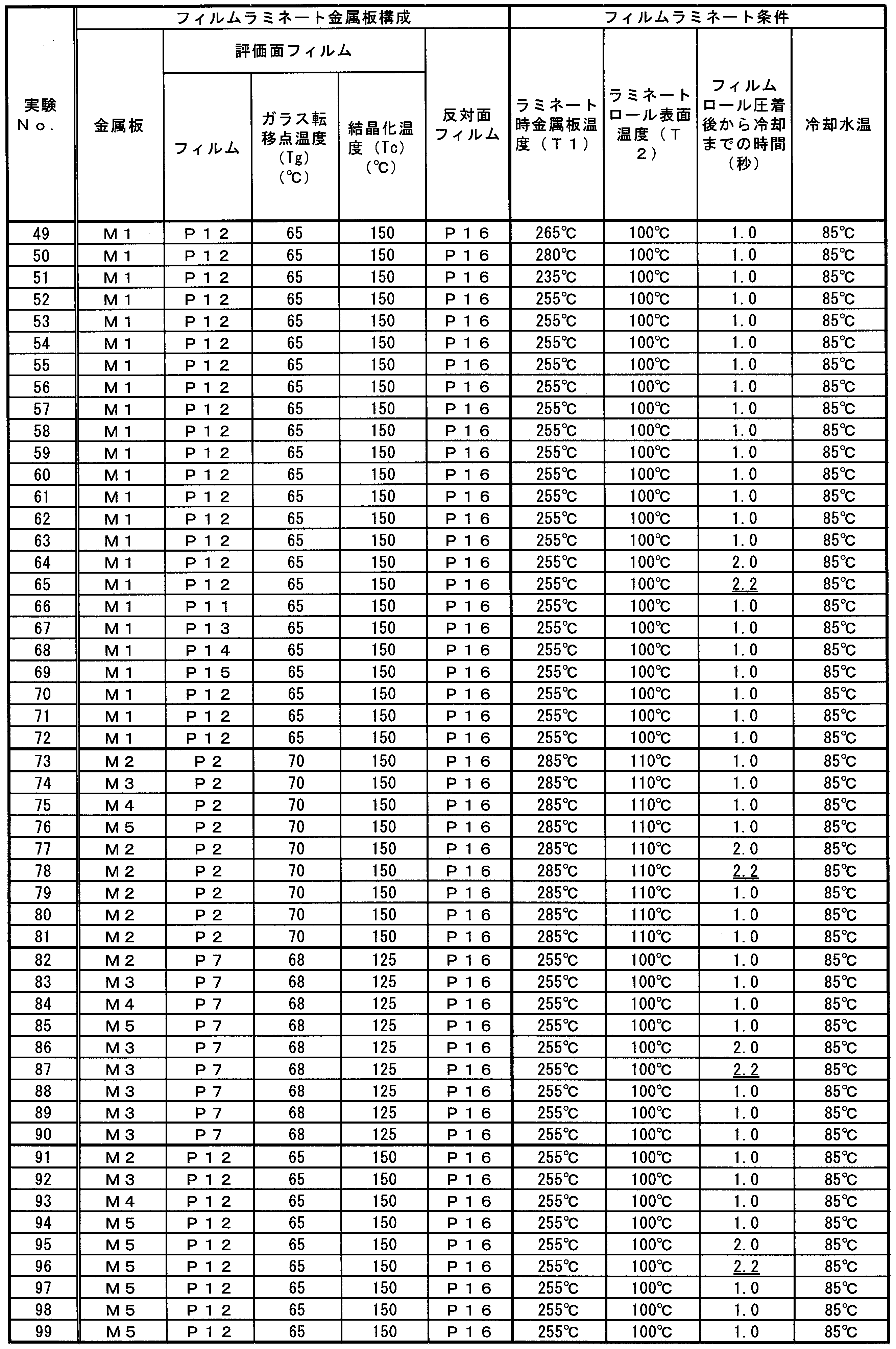
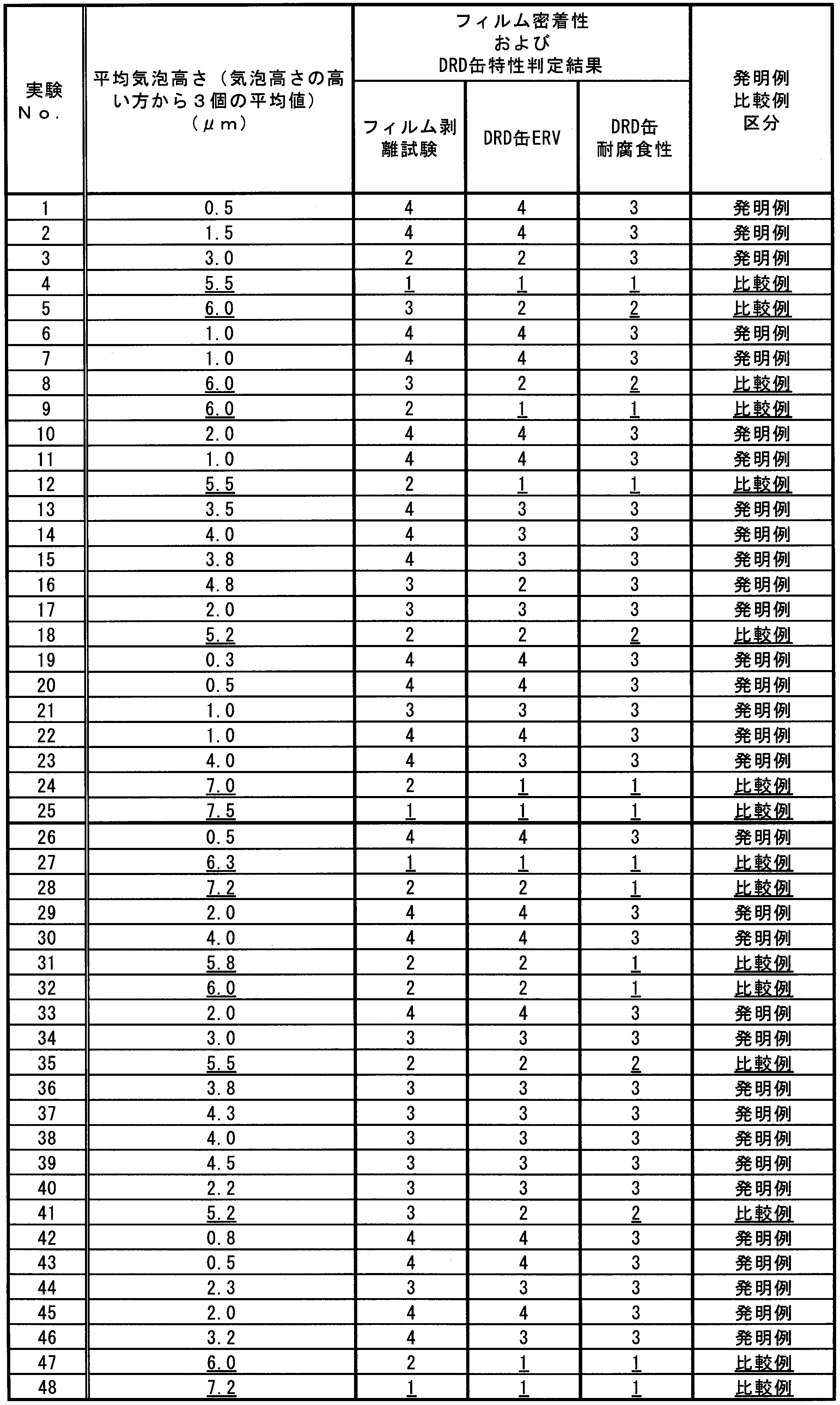
- the film laminated metal plate obtained by laminating the resin film shown in Table 2 on the metal plate shown in Table 1 on the metal plate under the conditions shown in Table 3 is left unbaked and after being baked.
- a 180 ° film peeling test piece having a width of 30 mm was prepared, and the peeling length of the film after retorting at 125 ° C. for 30 minutes was measured with a 100 g weight suspended on one side.
- Evaluation of the can body molded article measured the degree of film damage by measuring the inner surface ERV value after DRD cans of the film-laminated metal plate. Moreover, the food simulation liquid (3% sodium chloride aqueous solution) was put in the can made from DRD, and the retort process for 90 minutes was performed at 125 degreeC, and the presence or absence of the spot rust generation
- Metal plate M1 to M5 metal plates shown in Table 1 were used. When the metal plate is a plated steel plate or a chemical conversion treated steel plate, the contents are also shown below.
- M1 is a tin-free steel plate having a metal chromium layer (80 mg / m 2 ) and a chromium hydrated oxide layer (10 mg / m 2 ) on the steel plate surface.
- M2 is a reflow-treated tin-plated steel sheet.
- an Sn—Fe alloy layer (1.3 g / m 2 ), a pure Sn layer (1.5 g / m 2 ), a chromium hydrated oxide layer (10 mg / m 2 ) m 2 ), a so-called tin plate.
- M3 is a reflow-processed tin-plated steel sheet, from the steel sheet side, Sn—Fe alloy layer (1.3 g / m 2 ), Sn layer (1.5 g / m 2 ), ZrO 2 (Zr amount 5 mg / m 2 ).
- This is a chromate-free Sn-plated steel sheet having a chromate-free type chemical conversion treatment film mainly composed of.
- M4 is a reflow-treated tin-plated steel sheet, and from the steel sheet side, a Sn—Fe alloy layer (1.3 g / m 2 ), a Sn layer (1.5 g / m 2 ), TiO 2 (Ti amount 5 mg / m 2 )
- This is a chromate-free Sn-plated steel sheet having a chromate-free type chemical conversion treatment film mainly composed of.
- M5 is a chromate-free type aluminum plate having a chromate-free type chemical conversion treatment film in which a film layer of ZrO 2 (Zr amount 5 mg / m 2 ) is formed on an aluminum alloy plate (A5052).
- the polyester film includes a biaxially stretched film of polyethylene terephthalate (PET) shown in P1 to P5, and a biaxially stretched film (IA) of a copolymer of polyethylene terephthalate and polyethylene isophthalate shown in P6 to P10 (isophthalate is 12 mol%).
- PET polyethylene terephthalate
- IA biaxially stretched film
- -PET a copolymer of polyethylene terephthalate and polybutylene terephthalate shown in P10 to P15
- PET-PBT a copolymer of polyethylene terephthalate and polyethylene isophthalate shown in P16 (isophthalate is 12 mol%)
- a film (IA-PET) was used.
- the glass transition temperature (Tg) and the crystallization temperature (Tc) of the polyester film were determined from the endothermic peak and the temperature of the exothermic peak when the film was thermally analyzed with a differential scanning calorimeter. More specifically, with a DSC7030 manufactured by Hitachi High-Tech Science Co., Ltd., the temperature was measured by heating 8 mg of a film enclosed in an aluminum pan at a heating rate of 10 ° C./min.
- the elongation of the polyester film was measured by the following method.
- the film was cut into 10 mm ⁇ 70 mm, and cellophane tape was applied to the 20 mm portions at both ends to reinforce, thereby preparing tensile test pieces.
- the tensile test was performed by setting the distance between chucks of the tensile tester to 30 mm, fixing the gripping portions 20 mm at both ends of the thin film test piece to the chuck portion with the chuck, and measuring at 20 mm / min.
- the elongation was calculated by dividing the chuck moving distance when the thin film test piece was broken by the original chuck distance of 30 mm and displaying the value as a percentage.
- Film Laminating Method As a method for laminating the film, a dedicated film laminating apparatus was used. Film laminating equipment, metal belt feeding equipment, metal heating rolls for heating metal plates, front and back film feeding equipment, heat-resistant rubber laminating rolls (controlling the surface temperature of rubber rolls with metal heating backup rolls), cooling Equipped with water tank, roll for rolling plate (1-4 rolls of film laminate metal plate can be changed after cooling by changing the plate pass), and film laminate metal plate take-up device It is an apparatus that can produce a film-laminated metal band by continuously passing a metal band having a plate width of 300 mm.
- the schematic configuration of the film laminating apparatus is as shown in FIG.
- Tables 4 and 5 show the composition of the film laminate metal plate and the film lamination conditions (temperature of the metal plate when laminating the film on the metal plate, surface temperature of the laminate roll, time until cooling, cooling water temperature). Whether the surface temperature of the laminated metal plate on the outlet side of the cooling bath, the number of roll windings, the surface temperature of the laminated metal plate immediately after passing through each roll, the glass transition temperature (Tg) or more, and less than the crystallization temperature (Tc) Tables 6 and 7 (when glass transition temperature (Tg) or higher and lower than crystallization temperature (Tc)) or Bad (when glass transition temperature (Tg) or higher and crystallization temperature (Tc) falls below lower) Indicated.
- Bubble height measurement method The measurement of the bubble between the film of a film lamination metal plate and a metal plate was measured with the following method.
- a sample of 10 mm ⁇ 10 mm was cut and sampled from any of the laminated steel plate samples having a width of 20 cm and a length of 30 cm, and the film surface of each sample was laser-microscope (Laser microscope VK-8710 manufactured by Keyence Corporation, calculator VK). -8700) was used to take images of 10 fields of view at a magnification of 200 times (field of view: 0.50 mm x 0.705 mm), and the height of bubbles was measured using image analysis software.
- the height of the bubble is a line obtained by extracting a cross-sectional profile of the film surface of the bubble part from the bubble part laser microscope 3D profile image (eg, FIG. 5B) (eg, FIG. 5C) and connecting portions corresponding to both ends of the bubble with straight lines. Measure the length of the bubble from the highest point of the bubble to the baseline and use it as the bubble height to determine the bubble height for the top three bubbles from the highest bubble height of the three samples. was calculated as the average cell height of the produced film-laminated metal plate.
- Method for evaluating film adhesion of a film-laminated metal plate is as follows. First, a film laminate metal plate is cut into a width of 30 mm and a length of 150 mm, and a hole for hanging a weight is punched and opened at the end of the test piece, and then the test piece is placed 50 mm long from the side where the hole is made. The film on the opposite side and the metal plate are slit and cut, leaving only the film whose film adhesion is to be measured with a dedicated slit processing device. Next, the 50 mm long side of the slit-cut test piece was folded 180 ° to the remaining film side to obtain a test piece for film adhesion evaluation.
- the side of the test piece for film adhesion evaluation that is not drilled is vertically fixed to a dedicated fixture, and then a 100 g weight is suspended in the hole that is bent 180 °.
- the test piece with the weight suspended was placed in a retort kettle together with the fixed jig, retorted at 125 ° C. for 30 minutes, and evaluated by measuring the length of the peeled film.
- the film adhesion of the film laminated metal plate is determined by the above-mentioned film adhesion evaluation method, that is, 125 ° C. with a 100 g weight suspended on one side of a 180 ° film peeling test piece having a width of 30 mm. It evaluated by the peeling length of the film after retorting for 30 minutes.
- Can body molding Film laminated metal plate is punched into a disk with a diameter of 155 mm by punching press, then a shallow drawn cup is obtained by a cupping press so that the resin film for evaluation becomes the inner surface, and then this shallow drawn cup is further deeply drawn Molding was performed, and the flange portion was punched and cut to finally obtain a can body (DRD can) having a diameter of 83 mm and a cup height of 46 mm.
- Can body molded product film soundness evaluation The soundness of the film after retorting of the can formed into a can body was performed by the following method. After washing the DRD cans with hexane to dissolve and remove the wax, tap water into the cans, retort (125 ° C, 30 minutes), and then evaluate the soundness of the film on the inner surface of the cans by ERV test did. In the ERV test, the soundness of the can film was measured by adding an ERV test solution to which 0.2 g / l of 1% saline and surfactant (Nissan Chemical Rapisol) was added to the can.
- Criteria for soundness evaluation of can body molded product film ERV measurement of a can body (DRD can) formed into a diameter of 83 mm and a cup height of 46 mm uses a digital enamelator (model: NDE-1200) manufactured by Nichia Kogyo Co., Ltd. Remove the film on the outer surface of the can with sandpaper, connect the clip of the positive electrode of the digital enamelator, immerse the terminal rod of the negative electrode of the digital enamelator in the ERV test solution in the can, and The measurement was performed by measuring the value of the current flowing when a voltage of 6.3 V was applied between the positive and negative electrodes.
- Corrosion Resistance Evaluation Test A food simulation solution (3% sodium chloride aqueous solution) was placed in the obtained DRD can and retort treatment was performed at 125 ° C. for 90 minutes. After the retort treatment, whether or not corrosion occurred on the inner surface side of the can was visually determined according to the following criteria, and 3 was accepted and 2 and 1 were rejected. 3: No corrosion occurred 2: The film was not peeled off, but spot rust occurred on the inner surface of the can 1: Spotted film floating occurred on the can wall, and rust occurred
- the film-laminated metal plate of the present invention is excellent in that there are very few harmful bubbles that adversely affect film adhesion and corrosion resistance after canning between the metal plate and the film. Retort adhesion and corrosion resistance.
- the film laminated metal plate according to the present embodiment has a low average bubble height of the film, a reduced film peeling length after retort treatment, improved adhesion, and corrosion caused by bubbles can be greatly reduced. It is extremely useful as a film laminated metal plate for food containers.
Landscapes
- Engineering & Computer Science (AREA)
- Mechanical Engineering (AREA)
- Quality & Reliability (AREA)
- Laminated Bodies (AREA)
- Lining Or Joining Of Plastics Or The Like (AREA)
- Details Of Rigid Or Semi-Rigid Containers (AREA)
Abstract
Description
本願は、2016年3月10日に、日本に出願された特願2016-46897号に基づき優先権を主張し、その内容をここに援用する。
気泡を巻き込んだ状態のまま減圧されると、フィルムの幅方向端部付近の気泡は抜けやすいため、フィルムの幅方向端部ではラミネートロールとフィルムの密着状態が高くなる。一方、フィルムの幅方向中央部付近に巻き込まれた気泡は、抜け難くなる。また、ラミネートロールと接していないフィルム外面側が減圧されることにより、むしろ、気泡が膨張してしまうため、気泡が膨張した状態のままでフィルムがラミネートロールで圧着されると気泡が破裂し、ピンホールになりやすい欠点がある。
また、高速で連続的にフィルムをラミネートする設備において、圧着ロールの上流側に位置する空間の減圧状態を維持するのは困難であり、現実的な方法とは言い難い。
ここでいう有害な気泡とは、フィルムラミネート金属板のフィルムと金属板との間に存在する気泡が、気泡高さのうち高いものから上位3個の平均高さが5μm超の気泡である。この有害な気泡を少なくすることにより、ラミネート金属板として必要なレトルト密着性が向上し、製缶後の缶特性に優れたフィルムラミネート金属板が得られることを見出した。
(1)本発明の一態様に係るレトルト密着性に優れたフィルムラミネート金属板は、金属板と、前記金属板の表面に熱融着された樹脂フィルムと、前記金属板と前記樹脂フィルムとの間に含まれる気泡とを備え、前記気泡に対して、レーザー顕微鏡の3D解析画像を用いて気泡高さを測定したとき、前記気泡高さの高いものから上位3個の平均が0μm以上5.0μm以下であり、容器に加工した際に前記容器の内面側となる側の前記樹脂フィルムを残して前記金属板の長手方向の一端側の一部を切り取った試験片を用い、前記試験片の前記一端側に100gの錘を吊るし、前記試験片の前記長手方向の他端側に180°折り返した状態で、前記試験片に125℃の温度下で30分間レトルト処理を行ったときに、前記樹脂フィルムが前記金属板から剥離した長さが、15mm以下である。
本実施形態に係るフィルムラミネート金属板10は、少なくとも容器に加工した際に容器の内面側となる側の樹脂フィルム5が、幅30mmの180°フィルム剥離試験片の片側に100gの錘を吊るした状態で125℃・30分間レトルト処理した後のフィルムの剥離長さが15mm以下であり、かつ、樹脂フィルム5と金属板1の間に存在する気泡3が、レーザー顕微鏡の3D解析画像から得られる気泡高さ測定値のうち、当該気泡高さ測定値の高いものから上位3個の平均が0μm以上5.0μm以下であることを特徴とする。
これにより、本実施形態に係るフィルムラミネート金属板10は、レトルト処理後のフィルム剥離長さが小さくなり、密着性が向上し、気泡を起因とする腐食が大幅に低減できる。
以下、本実施形態に係るフィルムラミネート金属板10及びその製造方法を詳細に説明する。
本実施形態に係るフィルムラミネート金属板10は、樹脂フィルム5をラミネートするための金属板1を備える。この金属板1は、すずめっき鋼板、ティンフリー鋼板、冷延鋼板、ステンレス鋼板、アルミニウム板、チタン板などいずれでもよく、特に限定されるものではない。しかしながら、食品衛生性、加工性、耐食性、フィルム密着性、材料価格の観点から、すずめっき鋼板、あるいは、ティンフリー鋼板が、好適である。
そのため、金属板1の表面粗さは、平均粗さRaで、0.05μm以上、0.8μm以下の範囲が好ましい。より好ましくは、0.1μm以上、0.6μm以下である。
本実施形態に係るフィルムラミネート金属板10は、金属板1の表面上に樹脂フィルム5を備える。
固有粘度={ln(t/t0)}/C (i)
なお、式中Cは溶液100ml当たりの樹脂のg数で表した濃度を、t0は溶媒の流下時間(単位:秒)を、tは溶液の流下時間(単位:秒)を各々表す。
樹脂フィルム5の熱収縮率は15%以下が好ましい。熱収縮率が15%を超える場合、製缶後に缶胴部に印刷焼付け処理を行う缶に適用すると、フランジ部でフィルムが剥離する場合があるので好ましくない。また、熱収縮率が15%を超える場合、高温でレトルト滅菌処理を施す用途に用いられると、レトルト時にフィルム密着性が低下して剥離することがあるので好ましくない。
樹脂フィルム5の伸びが、100%未満の場合、フィルムラミネート金属板10として缶や缶蓋に加工する際、曲げ半径の小さい部分で樹脂フィルム5の表面が割れる場合がある。このような割れは、特に蓋内面側では腐食発生の起点になるので好ましくない。
発明者らが気泡3とフィルム密着性との関係について、鋭意調査したところ、以下のようなことが判明した。図1は平均気泡高さとレトルト後フィルム剥離長さとの関係について、樹脂フィルム5を金属板1にラミネートした後のパスライン搬送ロールに巻き付けた回数の影響を示したものである。
以上の理由から、樹脂フィルム5と金属板1との間に存在する気泡3の気泡高さを、高いものから上位3個の平均高さ(平均気泡高さ)が0μm以上5.0μm以下とするのが好ましい。また、製缶時に金型と樹脂フィルム5の表面とが摺動される際に気泡3の頂点付近が損傷されやすく、気泡3の損傷程度が大きいと、フィルムピンホールとなりやすく、耐食性が悪くなる原因となるので、好ましくない。
なお、上述では、平均気泡高さの下限を0μm以上としたが、2μm以上であれば、実用上好適なレトルト密着性を得ることができる。そのため、平均気泡高さは、2μm以上5.0μm以下であってもよい。
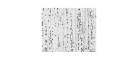
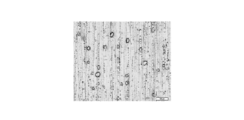
図2に示す樹脂フィルム5のガラス転位点温度(Tg)以上でロール1回巻き付けした場合の気泡3の状態に比べて、図3に示す樹脂フィルム5のガラス転位点温度(Tg)以上でロールに3回巻き付けした場合の方が、気泡3のサイズおよび個数が減少していることがわかる。
しかしこれらの写真からは、個数が減っているからレトルト後フィルム剥離長さが改善されるであろうことは推定できるが、図1のように平均気泡高さが小さくなっていることでレトルト後フィルム剥離長さが改善されることは判別できない。
気泡高さの測定は、レーザー顕微鏡の3Dプロファイル測定機能を使用して、フィルムラミネート金属板10の樹脂フィルム5表面のプロファイルを0.1μm以下の解像度で測定し、画像解析処理により、気泡3表面の断面プロファイルを抽出して気泡3の頂点から気泡3の両端に引いたベースラインに垂線を下ろして、気泡3の頂点からベースラインまでの距離を解析することで測定できる。
測定の概要を図5A~図5Cを用いて説明する。図5Aは気泡3の外観写真例、図5Bは気泡3のレーザー顕微鏡3Dプロファイル画像例、図5Cはレーザー顕微鏡3Dプロファイル画像から気泡3の断面プロファイルを抽出し気泡高さを解析した例である。
平均気泡高さが0μm以上5.0μm以下であるフィルムラミネート金属板10の製造方法を以下に詳細に述べる。
従って、樹脂フィルム5を金属板1に熱融着させた後の冷却は、板温度を樹脂フィルム5のガラス転位点温度(Tg)以上、樹脂フィルム5の結晶化温度(Tc)未満の温度に保持するのが好ましい。
その理由はフィルムラミネート金属板10の樹脂フィルム5面に圧力を加えるためであるが、フィルムラミネート金属板10の表裏面をロールで挟みこんでフィルム表面を圧下する方法もあるが、ロールとフィルムラミネート金属板10との接触時間が短く、気泡3を拡散させるだけの時間が得られないので好ましくない。さらに設備的に圧下装置を含み大がかりな装置となるので、前述の結晶化温度(Tc)未満の温度まで冷却する時間の2.0秒以下や、ガラス転移点温度(Tg)以上、かつ、フィルムの結晶化温度(Tc)未満の温度範囲を確保することが困難となるため好ましくない。
また、ロール以外の方法として、ホットプレスでフィルムラミネート金属板10の表裏面に圧力を加える方法も考えられるが、高速で移動するフィルムラミネート金属板10をホットプレスで連続的に挟みこむのは、現実的には困難である。巻きつけ回数も既設ラミネート金属板製造設備の張力仕様からも、一度の巻きつけでフィルムラミネート金属板10に必要以上に高い張力をかけることは困難、もしくは相当の設備改造を要することから好ましくない。
簡易に高速通板性を達成することを考慮すると、フィルムラミネート金属板10をロールに巻き付けて張力を加える方法が、設備が簡素で、かつラミネート後の通板パスライン確保の観点からも、ガラス転移点温度(Tg)以上、かつ、樹脂フィルム5の結晶化温度(Tc)未満の温度範囲で搬送用ロールとしてロールを配置し、それに巻きつけられることで圧下を確保することが最も好ましい方法である。
ロール1本当たりロール周長比で20%以上、55%以下の長さの範囲で巻きつける点については、金属板1とロールとの接触がロール周長の1/4~半周程度がフィルムラミネート金属板10に張力をかけた際の気泡3の垂直方向からの圧力がかかりやすいため、ロール周長比で20%以上、55%以下の長さの範囲でロールにフィルムラミネート金属板10を接触させることが望ましく、かつ、大幅な設備改造を伴わないので好ましいためである。
ロールへの巻きつけの際のフィルムラミネート金属板10の張力が20N/mm2未満の場合、フィルムラミネート金属板10の板厚方向にかかる圧力が低くなり、気泡3が抜け難くなるので、気泡高さのばらつきが大きくなるので、好ましくない。また、フィルムラミネート金属板10の張力が60N/mm2を超えると圧下力が高すぎて、ロールからフィルムラミネート金属板10が離れた際に気泡3が膨張する場合があり、かえって、気泡高さのばらつきが大きくなるので、好ましくない。尚、より好ましくはフィルムラミネート金属板10の通板張力を40N/mm2以上、60N/mm2以下とすれば、さらに平均気泡高さが低位安定する。
容器に加工した際に容器の内面側となる側の樹脂フィルム5を残して金属板1の長手方向の一端側の一部を切り取り、幅30mmの試験片を作製する。試験片の一端側に100gの錘を吊るし、試験片の長手方向の他端側に180°折り返す。この状態で、試験片に対して125℃の温度下で30分間レトルト処理を施す。レトルト処理を施した後、樹脂フィルム5が金属板1から剥離した長さを測定する。
具体的には以下の通りである。
表1に示すM1~M5の金属板を用いた。金属板がめっき鋼板、または化成処理鋼板である場合、その内容も以下に示した。
M1~M5は、厚さ0.20mm、表面粗度Ra=0.3μmの金属板を5%水酸化ナトリウム水溶液中で陰極電解処理してアルカリ脱脂した金属板である。M1は、鋼板表面に金属クロム層(80mg/m2)、クロム水和酸化物層(10mg/m2)があるティンフリー鋼板である。M2は、リフロー処理したすずめっき鋼板であり、鋼板側からSn-Fe合金層(1.3g/m2)、純Sn層(1.5g/m2)、クロム水和酸化物層(10mg/m2)がある、所謂ブリキ鋼板である。M3は、リフロー処理したすずめっき鋼板であり、鋼板側からSn-Fe合金層(1.3g/m2)、Sn層(1.5g/m2)、ZrO2(Zr量5mg/m2)を主体とするクロメートフリータイプの化成処理皮膜を有するクロメートフリーSnめっき鋼板である。M4は、リフロー処理したすずめっき鋼板であり、鋼板側からSn-Fe合金層(1.3g/m2)、Sn層(1.5g/m2)、TiO2(Ti量5mg/m2)を主体とするクロメートフリータイプの化成処理皮膜を有するクロメートフリーSnめっき鋼板である。M5は、アルミニウム合金板(A5052)上にZrO2(Zr量5mg/m2)の皮膜層を形成させたクロメートフリータイプの化成処理皮膜を有するクロメートフリータイプのアルミニウム板である。

表2に示すP1~P16のポリエステルフィルムを用いた。
ポリエステルフィルムとしては、P1~P5に示すポリエチレンテレフタレート(PET)の2軸延伸フィルム、P6~P10に示すポリエチレンテレフタレートとポリエチレンイソフタレートの共重合体(イソフタレートが12mol%)の2軸延伸フィルム(IA-PET)、P10~P15に示すポリエチレンテレフタレートとポリブチレンテレフタレートとの共重合体(PET-PBT)、P16に示すポリエチレンテレフタレートとポリエチレンイソフタレートの共重合体(イソフタレートが12mol%)の2軸延伸フィルム(IA-PET)を用いた。
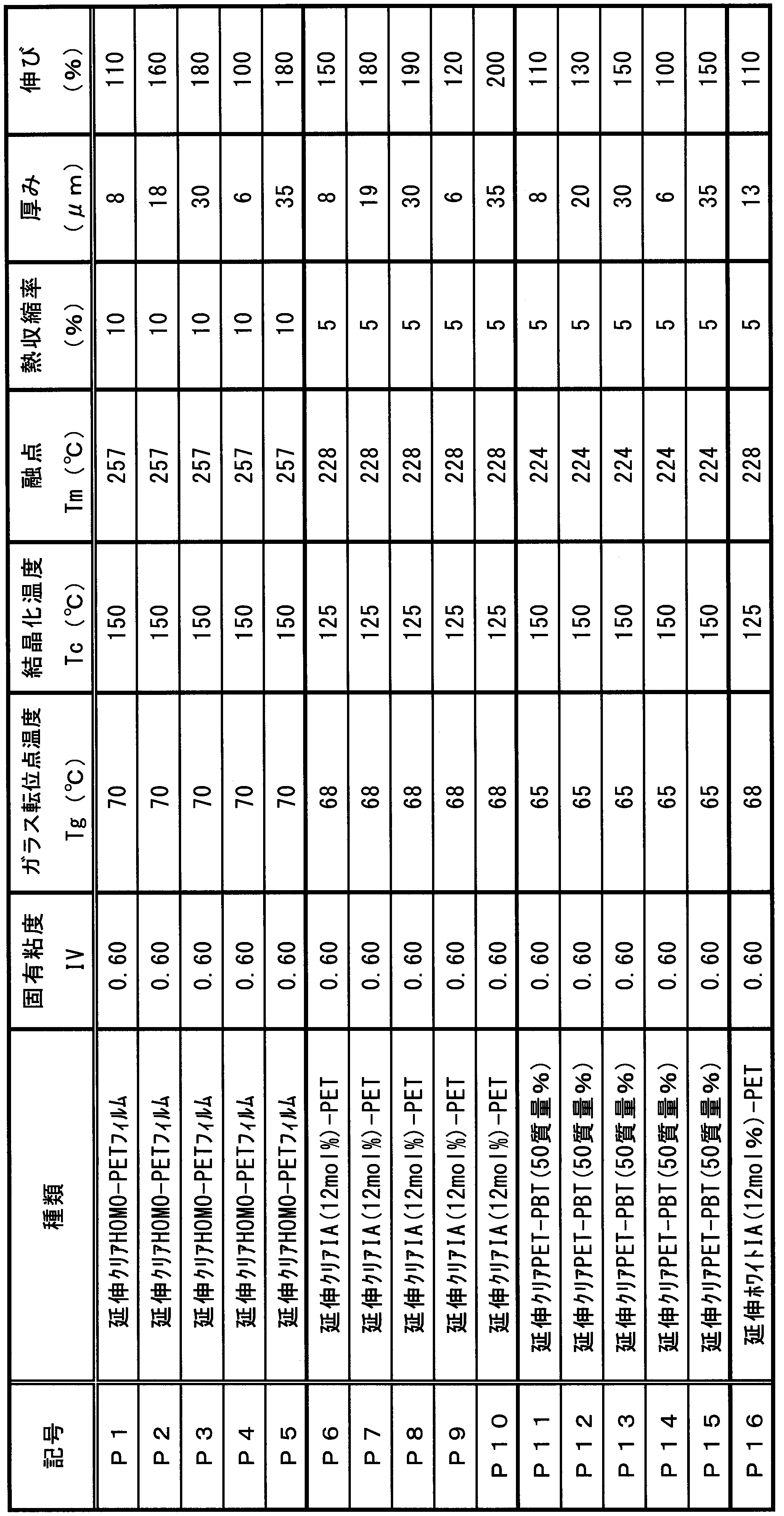
フィルムを10mm×70mmに切断し、その両端の20mm部分にセロハンテープを貼って補強し、引張試験片を作製した。引張試験は、引張試験機のチャック間距離を30mmに設定してから、チャック部に薄膜試験片の両端のつかみ部20mmをチャックに挟んで固定し、20mm/分の測定で行った。伸びの計算は、薄膜試験片が破断したときのチャックの移動距離を元のチャック間距離の30mmで割り、その値を百分率表示する方法とした。
フィルムのラミネート方法としては、専用のフィルムラミネート装置によった。フィルムラミネート装置は、金属帯給装装置、金属板加熱用の金属製加熱ロールと、表裏面のフィルム給装装置、耐熱ゴム製ラミネートロール(金属製加熱バックアップロールによりゴムロール表面温度を制御)、冷却用水槽、通板用ロール(通板パスの変更により冷却後のフィルムラミネート金属板のロールへの巻き付きを1本~4本に変更可能)、および、フィルムラミネート金属板の巻き取り装置を備えており、板幅300mmの金属帯を連続通板してフィルムラミネート金属帯を作製することができる装置である。フィルムラミネート装置の構成概略は前述の図6に示したとおりである。



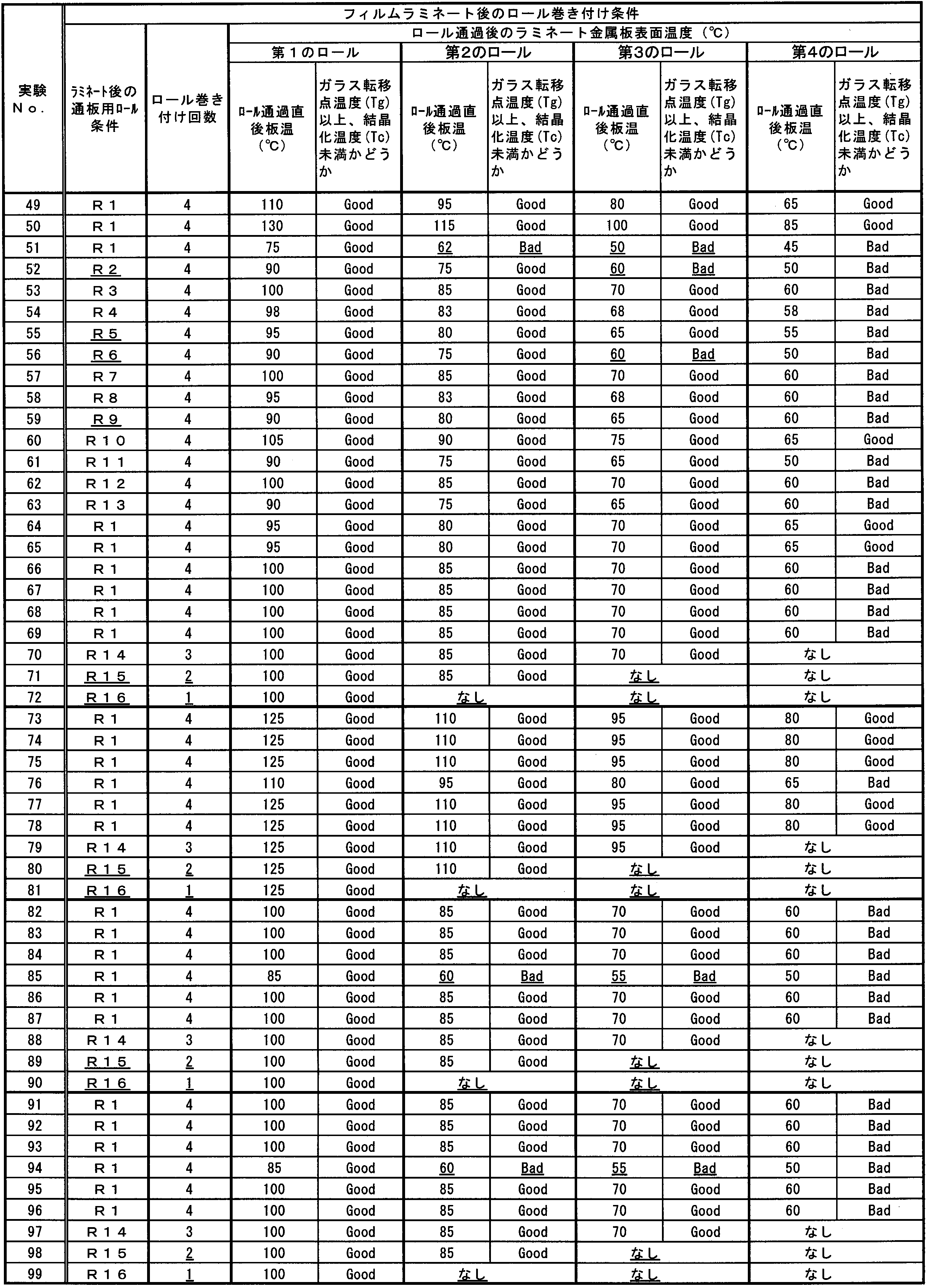
フィルムラミネート金属板のフィルムと金属板の間の気泡の測定は、以下の方法によって測定した。
幅20cm×縦30cmのラミネート鋼板試料の中から、任意の3箇所について10mm×10mmの試料を切断採取し、各試料のフィルム面をレーザー顕微鏡(株式会社キーエンス製レーザー顕微鏡VK-8710、演算機VK-8700)を用いて倍率200倍(視野:縦0.50mm×横0.705mm)で任意の10視野分の画像を撮影し画像解析ソフトで気泡の高さを測定した。
気泡の高さは気泡部レーザー顕微鏡3Dプロファイル画像(例:図5B)から気泡部のフィルム表面の断面プロファイルを抽出(例:図5C)し、気泡の両端に相当する部分を直線で結んだ線をベースラインとして、気泡の最も高い点からベースラインに垂線を下ろした時の長さを測定して気泡高さとし、3試料の中の最も高い気泡高さのものから上位3個分について、気泡の平均高さを計算し、作製したフィルムラミネート金属板の平均気泡高さとした。
フィルムラミネート金属板のフィルム密着性を評価する方法は以下の通りである。
まず、フィルムラミネート金属板を幅30mm長さ150mmに切断し、試験片の端に錘を吊るすための穴を打抜き加工して開け、次に試験片の穴を開けた側から50mm長さ位置に専用のスリット加工装置でフィルム密着性を測定するフィルムだけ残して反対面のフィルムと金属板をスリット加工して切断する。
次いで、スリット切断した試験片の50mm長さの側を残ったフィルム側に180°折り返し、フィルム密着性評価用の試験片とした。
フィルムの密着性は、フィルム密着性評価用試験片の穴を開けていない側を専用の固定冶具に垂直に立てて固定してから、180°に折り曲げた側にの穴に100gの錘を吊るし、錘を吊るした状態の試験片を固定冶具ごとレトルト釜の中に入れ、125℃・30分間レトルト処理し、フィルムが剥離した長さを測定することによって評価した。
フィルムラミネート金属板のフィルム密着性の判定は前記のフィルム密着性評価方法、すなわち、幅30mmの180°フィルム剥離試験片の片側に100gの錘を吊るした状態で125℃・30分間レトルト処理した後のフィルムの剥離長さで評価した。
4: 0mm ≦ 剥離長さ ≦ 5mm
3: 5mm < 剥離長さ ≦ 10mm
2: 10mm < 剥離長さ ≦ 15mm
1: 15mm <剥離長さ
フィルムラミネート金属板を打ち抜きプレスで直径155mmの円板に打ち抜き、つぎに評価用の樹脂フィルムが内面になるようにカッピングプレスにより浅絞りカップを得、次いでこの浅絞りカップをさらに深絞り成形し、フランジ部を打抜き切除して、最終的に直径83mm、カップ高さ46mmの缶体(DRD缶)を得た。
缶体に成形した缶のレトルト後のフィルムの健全性を以下の方法で行った。
DRD製缶した缶をヘキサンで洗浄してワックスを溶解除去した後、缶内に水道水を入れ、レトルト(125℃・30分)処理した後、缶内面のフィルムの健全性をERV試験によって評価した。
ERV試験は、缶の被膜の健全性を缶内に1%食塩水と界面活性剤(日産化学製ラピゾール)を0.2g/l添加したERV試験液を入れて、缶側外面側金属板とERV試験液の間の電気の導通を調べることにより、缶内面の健全性を評価する方法であり、一般に1mA以下程度であれば、缶として被膜の健全性が保たれていると判断される。
直径83mm、カップ高さ46mmに成形した缶体(DRD缶)のERV測定は、日亜計測工業有限会社製のデジタルエナメルレーター(型式:NDE-1200)を用い、缶の外面側のフィルムを紙やすりで除去してデジタルエナメルレーターの正極のクリップを接続し、缶内のERV試験液中に、デジタルエナメルレーターの負極の端子棒を浸漬させ、デジタルエナメルレーターで正負極間に6.3Vの電圧をかけた時に流れる電流値を測定することによって行った。
4: 0mA ≦ ERV ≦ 0.1mA
3: 0.1mA <ERV≦ 0.5mA
2: 0.5mA <ERV ≦ 1mA
1: 1mA <ERV
得られたDRD缶に食品模擬液(3%食塩水溶液)を入れて125℃で90分間のレトルト処理を行った。レトルト処理後、缶内面側に腐食が発生していないかどうか以下の基準で目視判定し、3を合格、2、1を不合格とした。
3: 腐食が全く発生していない
2: フィルム剥離していないが、缶内面に点錆が発生していた
1: 缶壁に斑点状のフィルム浮きが発生し、錆が発生していた

3 気泡
5 樹脂フィルム
10 フィルムラミネート金属板
20 フィルムラミネートロール
30 冷却槽
40 第1のロール
50 第2のロール
60 第3のロール
70 第4のロール
Claims (4)
- 金属板と;
前記金属板の表面に熱融着された樹脂フィルムと;
前記金属板と前記樹脂フィルムとの間に含まれる気泡と;
を備え、
前記気泡に対して、レーザー顕微鏡の3D解析画像を用いて気泡高さを測定したとき、前記気泡高さの高いものから上位3個の平均が0μm以上5.0μm以下であり、
容器に加工した際に前記容器の内面側となる側の前記樹脂フィルムを残して前記金属板の長手方向の一端側の一部を切り取った試験片を用い、前記試験片の前記一端側に100gの錘を吊るし、前記試験片の前記長手方向の他端側に180°折り返した状態で、前記試験片に125℃の温度下で30分間レトルト処理を行ったときに、前記樹脂フィルムが前記金属板から剥離した長さが、15mm以下である
ことを特徴とする、レトルト密着性に優れたフィルムラミネート金属板。 - 請求項1に記載のレトルト密着性に優れたフィルムラミネート金属板の製造方法であって、
前記樹脂フィルムの融点以上に加熱した前記金属板に、前記樹脂フィルムをフィルムラミネートロールで圧着し、
前記圧着後2.0秒以内に、前記樹脂フィルムのガラス転移点温度Tg以上、かつ、結晶化温度Tc未満の温度範囲に冷却し、
前記温度範囲内で、通板張力を20~60N/mm2として、少なくとも3回以上、ロール1本当たりロール周長比で20~55%の長さの範囲で巻きつけて通過させる
ことを特徴とする、レトルト密着性に優れたフィルムラミネート金属板の製造方法。 - 前記通板張力が、40~60N/mm2である
ことを特徴とする、請求項2に記載のレトルト密着性に優れたフィルムラミネート金属板の製造方法。 - 前記フィルムラミネート金属板を巻きつける前記ロールの直径の少なくとも1つが、200~600mmの範囲内である
ことを特徴とする、請求項2又は3に記載のレトルト密着性に優れたフィルムラミネート金属板の製造方法。
Priority Applications (4)
| Application Number | Priority Date | Filing Date | Title |
|---|---|---|---|
| CN201780015606.4A CN108698376B (zh) | 2016-03-10 | 2017-03-10 | 蒸煮密合性优异的膜层压金属板及其制造方法 |
| JP2017549822A JP6380688B2 (ja) | 2016-03-10 | 2017-03-10 | レトルト密着性に優れるフィルムラミネート金属板およびその製造方法 |
| EP17763445.8A EP3427944B1 (en) | 2016-03-10 | 2017-03-10 | A method for manufacturing a film laminate metal plate having excellent retort adhesiveness |
| US16/082,756 US11220094B2 (en) | 2016-03-10 | 2017-03-10 | Film-laminated metal plate having excellent retort adhesiveness, and method for manufacturing same |
Applications Claiming Priority (2)
| Application Number | Priority Date | Filing Date | Title |
|---|---|---|---|
| JP2016046897 | 2016-03-10 | ||
| JP2016-046897 | 2016-03-10 |
Publications (1)
| Publication Number | Publication Date |
|---|---|
| WO2017155113A1 true WO2017155113A1 (ja) | 2017-09-14 |
Family
ID=59790458
Family Applications (1)
| Application Number | Title | Priority Date | Filing Date |
|---|---|---|---|
| PCT/JP2017/009804 Ceased WO2017155113A1 (ja) | 2016-03-10 | 2017-03-10 | レトルト密着性に優れるフィルムラミネート金属板およびその製造方法 |
Country Status (6)
| Country | Link |
|---|---|
| US (1) | US11220094B2 (ja) |
| EP (1) | EP3427944B1 (ja) |
| JP (1) | JP6380688B2 (ja) |
| CN (1) | CN108698376B (ja) |
| TW (1) | TWI658924B (ja) |
| WO (1) | WO2017155113A1 (ja) |
Cited By (3)
| Publication number | Priority date | Publication date | Assignee | Title |
|---|---|---|---|---|
| JP2020016652A (ja) * | 2018-07-17 | 2020-01-30 | 日東電工株式会社 | 積層体を評価する方法、積層体を評価する装置、積層体を製造する方法、及び積層体を製造する装置 |
| WO2021006024A1 (ja) * | 2019-07-05 | 2021-01-14 | 日本製鉄株式会社 | 樹脂フィルムラミネート金属板、および、その製造方法 |
| CN119584429A (zh) * | 2024-12-03 | 2025-03-07 | 无锡市五十五度科技有限公司 | 异型结构散热板与印制板膜粘工艺 |
Citations (9)
| Publication number | Priority date | Publication date | Assignee | Title |
|---|---|---|---|---|
| JPS61149340A (ja) * | 1984-12-25 | 1986-07-08 | Toyo Kohan Co Ltd | ポリエステル樹脂フイルム被覆金属板の製造方法 |
| JPH0890717A (ja) * | 1994-09-27 | 1996-04-09 | Kawasaki Steel Corp | ポリエステル樹脂ラミネート金属板およびその製造方法 |
| JPH10195210A (ja) * | 1997-01-06 | 1998-07-28 | Unitika Ltd | 金属板ラミネート用ポリエステルフィルム及びそのフィルムを用いたラミネート金属板の製造方法 |
| JPH1110796A (ja) * | 1997-06-27 | 1999-01-19 | Nippon Steel Corp | 熱可塑性樹脂被覆金属板の製造方法 |
| JP2000158583A (ja) * | 1998-11-30 | 2000-06-13 | Nkk Corp | ラミネート金属板の製造方法 |
| JP2004237549A (ja) * | 2003-02-05 | 2004-08-26 | Daiwa Can Co Ltd | 熱可塑性樹脂被覆金属板の製造方法 |
| JP2004358660A (ja) * | 2003-04-11 | 2004-12-24 | Seiji Kagawa | プラスチックラミネート金属板及びその製造方法、並びにプラスチックラミネート金属板からなる缶 |
| JP2007245441A (ja) * | 2006-03-15 | 2007-09-27 | Jfe Steel Kk | 表面清浄性の優れるポリエチレンテレフタレート被覆鋼板の製造方法 |
| JP2009184262A (ja) * | 2008-02-07 | 2009-08-20 | Jfe Steel Corp | 2ピース缶体用ラミネート金属板および2ピースラミネート缶体 |
Family Cites Families (8)
| Publication number | Priority date | Publication date | Assignee | Title |
|---|---|---|---|---|
| JPS63233824A (ja) | 1987-03-23 | 1988-09-29 | Nippon Steel Corp | 積層鋼板製造時の空気巻込み防止方法 |
| JP3160740B2 (ja) | 1993-12-24 | 2001-04-25 | 新日本製鐵株式会社 | 減圧ラミネート法 |
| EP0730952A3 (en) | 1995-03-07 | 1997-06-11 | Nippon Steel Corp | Process for laminating a metal strip with plastic film, laminate produced thereafter, and can made therefrom |
| US6200409B1 (en) * | 1996-05-14 | 2001-03-13 | Toyo Kohan., Ltd. | Method and apparatus for manufacturing metallic sheet covered with thermoplastic resin |
| TW457183B (en) * | 1997-07-09 | 2001-10-01 | Toray Ind Co Ltd | Method of producing thermoplastic resin films and apparatus for producing the same |
| US6663940B1 (en) * | 1999-04-16 | 2003-12-16 | Toyo Boseki Kabushiki Kaisha | Polypropylene multi-layer sealant films for retort packaging |
| EP2677567B1 (en) * | 2011-02-18 | 2018-06-13 | Kabushiki Kaisha Toshiba | Method for manufacturing electrode and method for manufacturing battery |
| JP5874659B2 (ja) | 2013-02-28 | 2016-03-02 | Jfeスチール株式会社 | 2ピース缶用ラミネート金属板および2ピースラミネート缶体 |
-
2017
- 2017-03-10 US US16/082,756 patent/US11220094B2/en active Active
- 2017-03-10 EP EP17763445.8A patent/EP3427944B1/en active Active
- 2017-03-10 CN CN201780015606.4A patent/CN108698376B/zh active Active
- 2017-03-10 TW TW106108055A patent/TWI658924B/zh active
- 2017-03-10 JP JP2017549822A patent/JP6380688B2/ja active Active
- 2017-03-10 WO PCT/JP2017/009804 patent/WO2017155113A1/ja not_active Ceased
Patent Citations (9)
| Publication number | Priority date | Publication date | Assignee | Title |
|---|---|---|---|---|
| JPS61149340A (ja) * | 1984-12-25 | 1986-07-08 | Toyo Kohan Co Ltd | ポリエステル樹脂フイルム被覆金属板の製造方法 |
| JPH0890717A (ja) * | 1994-09-27 | 1996-04-09 | Kawasaki Steel Corp | ポリエステル樹脂ラミネート金属板およびその製造方法 |
| JPH10195210A (ja) * | 1997-01-06 | 1998-07-28 | Unitika Ltd | 金属板ラミネート用ポリエステルフィルム及びそのフィルムを用いたラミネート金属板の製造方法 |
| JPH1110796A (ja) * | 1997-06-27 | 1999-01-19 | Nippon Steel Corp | 熱可塑性樹脂被覆金属板の製造方法 |
| JP2000158583A (ja) * | 1998-11-30 | 2000-06-13 | Nkk Corp | ラミネート金属板の製造方法 |
| JP2004237549A (ja) * | 2003-02-05 | 2004-08-26 | Daiwa Can Co Ltd | 熱可塑性樹脂被覆金属板の製造方法 |
| JP2004358660A (ja) * | 2003-04-11 | 2004-12-24 | Seiji Kagawa | プラスチックラミネート金属板及びその製造方法、並びにプラスチックラミネート金属板からなる缶 |
| JP2007245441A (ja) * | 2006-03-15 | 2007-09-27 | Jfe Steel Kk | 表面清浄性の優れるポリエチレンテレフタレート被覆鋼板の製造方法 |
| JP2009184262A (ja) * | 2008-02-07 | 2009-08-20 | Jfe Steel Corp | 2ピース缶体用ラミネート金属板および2ピースラミネート缶体 |
Cited By (6)
| Publication number | Priority date | Publication date | Assignee | Title |
|---|---|---|---|---|
| JP2020016652A (ja) * | 2018-07-17 | 2020-01-30 | 日東電工株式会社 | 積層体を評価する方法、積層体を評価する装置、積層体を製造する方法、及び積層体を製造する装置 |
| JP7485503B2 (ja) | 2018-07-17 | 2024-05-16 | ツェット・エフ・オートモーティブ・ジャーマニー・ゲーエムベーハー | 積層体を評価する方法、積層体を評価する装置、積層体を製造する方法、及び積層体を製造する装置 |
| US12053968B2 (en) | 2018-07-17 | 2024-08-06 | Zf Automotive Germany Gmbh | Method for evaluating laminate, device for evaluating laminate, method for manufacturing laminate, and device for manufacturing laminate |
| WO2021006024A1 (ja) * | 2019-07-05 | 2021-01-14 | 日本製鉄株式会社 | 樹脂フィルムラミネート金属板、および、その製造方法 |
| CN113853303A (zh) * | 2019-07-05 | 2021-12-28 | 日本制铁株式会社 | 树脂膜层压金属板及其制造方法 |
| CN119584429A (zh) * | 2024-12-03 | 2025-03-07 | 无锡市五十五度科技有限公司 | 异型结构散热板与印制板膜粘工艺 |
Also Published As
| Publication number | Publication date |
|---|---|
| JP6380688B2 (ja) | 2018-08-29 |
| EP3427944A1 (en) | 2019-01-16 |
| EP3427944B1 (en) | 2021-07-14 |
| TWI658924B (zh) | 2019-05-11 |
| US11220094B2 (en) | 2022-01-11 |
| EP3427944A4 (en) | 2019-11-06 |
| TW201733796A (zh) | 2017-10-01 |
| US20190091985A1 (en) | 2019-03-28 |
| CN108698376B (zh) | 2021-01-01 |
| JPWO2017155113A1 (ja) | 2018-03-22 |
| CN108698376A (zh) | 2018-10-23 |
Similar Documents
| Publication | Publication Date | Title |
|---|---|---|
| FI96397B (fi) | Menetelmä ja laitteisto laminoitujen materiaalien valmistamiseksi | |
| JP5673860B2 (ja) | ラミネート金属板および食品用缶詰容器 | |
| JP6791157B2 (ja) | 樹脂被覆Snめっき鋼板、及びその製造方法 | |
| JP6380688B2 (ja) | レトルト密着性に優れるフィルムラミネート金属板およびその製造方法 | |
| EP2489760B1 (en) | Method for producing resin-coated metal plate | |
| JP7184196B2 (ja) | 樹脂フィルムラミネート金属板、および、その製造方法 | |
| JP4626532B2 (ja) | 表面処理鋼板およびその製造方法、ならびに樹脂被覆鋼板、缶および缶蓋 | |
| JP5300119B2 (ja) | シームレス缶用表面処理鋼板、樹脂被覆鋼板及びシームレス缶 | |
| CN104254643A (zh) | 容器用钢板及其制造方法 | |
| JP7080125B2 (ja) | ポリエステル樹脂被覆金属板、ポリエステル樹脂被覆金属板の製造方法、そのポリエステル樹脂被覆金属板からなる容器及び容器蓋 | |
| US20200346831A1 (en) | Heat sealed lid and can | |
| JPWO2000058087A1 (ja) | ポリエステル樹脂被覆金属板、およびそれを用いた缶 | |
| CN102257185B (zh) | 使锡以粒状析出的表面处理钢板及树脂被覆钢板 | |
| JP5884180B2 (ja) | 表面処理鋼板の製造方法および表面処理鋼板、ならびに樹脂被覆鋼板、缶および缶蓋 | |
| JP5078155B2 (ja) | 樹脂被覆金属板の製造方法 | |
| JP4872315B2 (ja) | 表面処理鋼板およびその製造方法、ならびに樹脂被覆鋼板、缶および缶蓋 | |
| JP4339046B2 (ja) | 樹脂被覆アルミニウム材の製造方法 | |
| WO2025094508A1 (ja) | フィルムラミネート鋼板及びdi缶の製造方法 | |
| JP5895879B2 (ja) | 表面処理鋼板、樹脂被覆鋼板およびそれらの製造方法、ならびに、缶および缶蓋 | |
| TW201244921A (en) | Surface treated sheet, its production method, and resin film coated steel sheet | |
| JP2012107335A (ja) | 表面処理金属板、樹脂被覆金属板、金属缶および缶蓋 | |
| JP2004345214A (ja) | 樹脂被覆Snめっき鋼板、それを用いた缶、および樹脂被覆Snめっき鋼板の製造方法 | |
| JP2019177892A (ja) | ヒートシール容器用缶体およびヒートシール容器 | |
| JP2000289146A (ja) | 樹脂ラミネート用金属帯及び金属帯のラミネート方法 |
Legal Events
| Date | Code | Title | Description |
|---|---|---|---|
| ENP | Entry into the national phase |
Ref document number: 2017549822 Country of ref document: JP Kind code of ref document: A |
|
| NENP | Non-entry into the national phase |
Ref country code: DE |
|
| WWE | Wipo information: entry into national phase |
Ref document number: 2017763445 Country of ref document: EP |
|
| ENP | Entry into the national phase |
Ref document number: 2017763445 Country of ref document: EP Effective date: 20181010 |
|
| 121 | Ep: the epo has been informed by wipo that ep was designated in this application |
Ref document number: 17763445 Country of ref document: EP Kind code of ref document: A1 |