WO2017158676A1 - Système moteur et son procédé de commande - Google Patents
Système moteur et son procédé de commande Download PDFInfo
- Publication number
- WO2017158676A1 WO2017158676A1 PCT/JP2016/057955 JP2016057955W WO2017158676A1 WO 2017158676 A1 WO2017158676 A1 WO 2017158676A1 JP 2016057955 W JP2016057955 W JP 2016057955W WO 2017158676 A1 WO2017158676 A1 WO 2017158676A1
- Authority
- WO
- WIPO (PCT)
- Prior art keywords
- engine
- intake valve
- load
- timing
- engine system
- Prior art date
- Legal status (The legal status is an assumption and is not a legal conclusion. Google has not performed a legal analysis and makes no representation as to the accuracy of the status listed.)
- Ceased
Links
Images




Classifications
-
- F—MECHANICAL ENGINEERING; LIGHTING; HEATING; WEAPONS; BLASTING
- F02—COMBUSTION ENGINES; HOT-GAS OR COMBUSTION-PRODUCT ENGINE PLANTS
- F02D—CONTROLLING COMBUSTION ENGINES
- F02D13/00—Controlling the engine output power by varying inlet or exhaust valve operating characteristics, e.g. timing
- F02D13/02—Controlling the engine output power by varying inlet or exhaust valve operating characteristics, e.g. timing during engine operation
- F02D13/0223—Variable control of the intake valves only
- F02D13/0234—Variable control of the intake valves only changing the valve timing only
- F02D13/0238—Variable control of the intake valves only changing the valve timing only by shifting the phase, i.e. the opening periods of the valves are constant
-
- F—MECHANICAL ENGINEERING; LIGHTING; HEATING; WEAPONS; BLASTING
- F02—COMBUSTION ENGINES; HOT-GAS OR COMBUSTION-PRODUCT ENGINE PLANTS
- F02D—CONTROLLING COMBUSTION ENGINES
- F02D13/00—Controlling the engine output power by varying inlet or exhaust valve operating characteristics, e.g. timing
- F02D13/02—Controlling the engine output power by varying inlet or exhaust valve operating characteristics, e.g. timing during engine operation
- F02D13/0269—Controlling the valves to perform a Miller-Atkinson cycle
-
- F—MECHANICAL ENGINEERING; LIGHTING; HEATING; WEAPONS; BLASTING
- F02—COMBUSTION ENGINES; HOT-GAS OR COMBUSTION-PRODUCT ENGINE PLANTS
- F02D—CONTROLLING COMBUSTION ENGINES
- F02D15/00—Varying compression ratio
- F02D15/04—Varying compression ratio by alteration of volume of compression space without changing piston stroke
-
- F—MECHANICAL ENGINEERING; LIGHTING; HEATING; WEAPONS; BLASTING
- F02—COMBUSTION ENGINES; HOT-GAS OR COMBUSTION-PRODUCT ENGINE PLANTS
- F02D—CONTROLLING COMBUSTION ENGINES
- F02D19/00—Controlling engines characterised by their use of non-liquid fuels, pluralities of fuels, or non-fuel substances added to the combustible mixtures
- F02D19/06—Controlling engines characterised by their use of non-liquid fuels, pluralities of fuels, or non-fuel substances added to the combustible mixtures peculiar to engines working with pluralities of fuels, e.g. alternatively with light and heavy fuel oil, other than engines indifferent to the fuel consumed
- F02D19/08—Controlling engines characterised by their use of non-liquid fuels, pluralities of fuels, or non-fuel substances added to the combustible mixtures peculiar to engines working with pluralities of fuels, e.g. alternatively with light and heavy fuel oil, other than engines indifferent to the fuel consumed simultaneously using pluralities of fuels
- F02D19/10—Controlling engines characterised by their use of non-liquid fuels, pluralities of fuels, or non-fuel substances added to the combustible mixtures peculiar to engines working with pluralities of fuels, e.g. alternatively with light and heavy fuel oil, other than engines indifferent to the fuel consumed simultaneously using pluralities of fuels peculiar to compression-ignition engines in which the main fuel is gaseous
- F02D19/105—Controlling engines characterised by their use of non-liquid fuels, pluralities of fuels, or non-fuel substances added to the combustible mixtures peculiar to engines working with pluralities of fuels, e.g. alternatively with light and heavy fuel oil, other than engines indifferent to the fuel consumed simultaneously using pluralities of fuels peculiar to compression-ignition engines in which the main fuel is gaseous operating in a special mode, e.g. in a liquid fuel only mode for starting
-
- F—MECHANICAL ENGINEERING; LIGHTING; HEATING; WEAPONS; BLASTING
- F02—COMBUSTION ENGINES; HOT-GAS OR COMBUSTION-PRODUCT ENGINE PLANTS
- F02D—CONTROLLING COMBUSTION ENGINES
- F02D41/00—Electrical control of supply of combustible mixture or its constituents
- F02D41/0025—Controlling engines characterised by use of non-liquid fuels, pluralities of fuels, or non-fuel substances added to the combustible mixtures
- F02D41/0027—Controlling engines characterised by use of non-liquid fuels, pluralities of fuels, or non-fuel substances added to the combustible mixtures the fuel being gaseous
-
- F—MECHANICAL ENGINEERING; LIGHTING; HEATING; WEAPONS; BLASTING
- F01—MACHINES OR ENGINES IN GENERAL; ENGINE PLANTS IN GENERAL; STEAM ENGINES
- F01L—CYCLICALLY OPERATING VALVES FOR MACHINES OR ENGINES
- F01L13/00—Modifications of valve-gear to facilitate reversing, braking, starting, changing compression ratio, or other specific operations
- F01L13/0015—Modifications of valve-gear to facilitate reversing, braking, starting, changing compression ratio, or other specific operations for optimising engine performances by modifying valve lift according to various working parameters, e.g. rotational speed, load, torque
- F01L13/0021—Modifications of valve-gear to facilitate reversing, braking, starting, changing compression ratio, or other specific operations for optimising engine performances by modifying valve lift according to various working parameters, e.g. rotational speed, load, torque by modification of rocker arm ratio
- F01L13/0026—Modifications of valve-gear to facilitate reversing, braking, starting, changing compression ratio, or other specific operations for optimising engine performances by modifying valve lift according to various working parameters, e.g. rotational speed, load, torque by modification of rocker arm ratio by means of an eccentric
-
- F—MECHANICAL ENGINEERING; LIGHTING; HEATING; WEAPONS; BLASTING
- F01—MACHINES OR ENGINES IN GENERAL; ENGINE PLANTS IN GENERAL; STEAM ENGINES
- F01L—CYCLICALLY OPERATING VALVES FOR MACHINES OR ENGINES
- F01L13/00—Modifications of valve-gear to facilitate reversing, braking, starting, changing compression ratio, or other specific operations
- F01L2013/10—Auxiliary actuators for variable valve timing
- F01L2013/103—Electric motors
-
- F—MECHANICAL ENGINEERING; LIGHTING; HEATING; WEAPONS; BLASTING
- F01—MACHINES OR ENGINES IN GENERAL; ENGINE PLANTS IN GENERAL; STEAM ENGINES
- F01L—CYCLICALLY OPERATING VALVES FOR MACHINES OR ENGINES
- F01L13/00—Modifications of valve-gear to facilitate reversing, braking, starting, changing compression ratio, or other specific operations
- F01L2013/10—Auxiliary actuators for variable valve timing
- F01L2013/106—Pneumatic motors
-
- F—MECHANICAL ENGINEERING; LIGHTING; HEATING; WEAPONS; BLASTING
- F02—COMBUSTION ENGINES; HOT-GAS OR COMBUSTION-PRODUCT ENGINE PLANTS
- F02D—CONTROLLING COMBUSTION ENGINES
- F02D19/00—Controlling engines characterised by their use of non-liquid fuels, pluralities of fuels, or non-fuel substances added to the combustible mixtures
- F02D19/02—Controlling engines characterised by their use of non-liquid fuels, pluralities of fuels, or non-fuel substances added to the combustible mixtures peculiar to engines working with gaseous fuels
-
- F—MECHANICAL ENGINEERING; LIGHTING; HEATING; WEAPONS; BLASTING
- F02—COMBUSTION ENGINES; HOT-GAS OR COMBUSTION-PRODUCT ENGINE PLANTS
- F02D—CONTROLLING COMBUSTION ENGINES
- F02D19/00—Controlling engines characterised by their use of non-liquid fuels, pluralities of fuels, or non-fuel substances added to the combustible mixtures
- F02D19/06—Controlling engines characterised by their use of non-liquid fuels, pluralities of fuels, or non-fuel substances added to the combustible mixtures peculiar to engines working with pluralities of fuels, e.g. alternatively with light and heavy fuel oil, other than engines indifferent to the fuel consumed
- F02D19/0639—Controlling engines characterised by their use of non-liquid fuels, pluralities of fuels, or non-fuel substances added to the combustible mixtures peculiar to engines working with pluralities of fuels, e.g. alternatively with light and heavy fuel oil, other than engines indifferent to the fuel consumed characterised by the type of fuels
- F02D19/0642—Controlling engines characterised by their use of non-liquid fuels, pluralities of fuels, or non-fuel substances added to the combustible mixtures peculiar to engines working with pluralities of fuels, e.g. alternatively with light and heavy fuel oil, other than engines indifferent to the fuel consumed characterised by the type of fuels at least one fuel being gaseous, the other fuels being gaseous or liquid at standard conditions
- F02D19/0647—Controlling engines characterised by their use of non-liquid fuels, pluralities of fuels, or non-fuel substances added to the combustible mixtures peculiar to engines working with pluralities of fuels, e.g. alternatively with light and heavy fuel oil, other than engines indifferent to the fuel consumed characterised by the type of fuels at least one fuel being gaseous, the other fuels being gaseous or liquid at standard conditions the gaseous fuel being liquefied petroleum gas [LPG], liquefied natural gas [LNG], compressed natural gas [CNG] or dimethyl ether [DME]
-
- F—MECHANICAL ENGINEERING; LIGHTING; HEATING; WEAPONS; BLASTING
- F02—COMBUSTION ENGINES; HOT-GAS OR COMBUSTION-PRODUCT ENGINE PLANTS
- F02D—CONTROLLING COMBUSTION ENGINES
- F02D41/00—Electrical control of supply of combustible mixture or its constituents
- F02D41/0002—Controlling intake air
- F02D2041/001—Controlling intake air for engines with variable valve actuation
-
- F—MECHANICAL ENGINEERING; LIGHTING; HEATING; WEAPONS; BLASTING
- F02—COMBUSTION ENGINES; HOT-GAS OR COMBUSTION-PRODUCT ENGINE PLANTS
- F02D—CONTROLLING COMBUSTION ENGINES
- F02D2200/00—Input parameters for engine control
- F02D2200/02—Input parameters for engine control the parameters being related to the engine
- F02D2200/10—Parameters related to the engine output, e.g. engine torque or engine speed
- F02D2200/1002—Output torque
-
- F—MECHANICAL ENGINEERING; LIGHTING; HEATING; WEAPONS; BLASTING
- F02—COMBUSTION ENGINES; HOT-GAS OR COMBUSTION-PRODUCT ENGINE PLANTS
- F02D—CONTROLLING COMBUSTION ENGINES
- F02D2200/00—Input parameters for engine control
- F02D2200/02—Input parameters for engine control the parameters being related to the engine
- F02D2200/10—Parameters related to the engine output, e.g. engine torque or engine speed
- F02D2200/101—Engine speed
-
- F—MECHANICAL ENGINEERING; LIGHTING; HEATING; WEAPONS; BLASTING
- F02—COMBUSTION ENGINES; HOT-GAS OR COMBUSTION-PRODUCT ENGINE PLANTS
- F02D—CONTROLLING COMBUSTION ENGINES
- F02D2700/00—Mechanical control of speed or power of a single cylinder piston engine
- F02D2700/02—Controlling by changing the air or fuel supply
- F02D2700/0202—Controlling by changing the air or fuel supply for engines working with gaseous fuel, including those working with an ignition liquid
- F02D2700/0207—Controlling the air or mixture supply
- F02D2700/0212—Engines with compressor
-
- F—MECHANICAL ENGINEERING; LIGHTING; HEATING; WEAPONS; BLASTING
- F02—COMBUSTION ENGINES; HOT-GAS OR COMBUSTION-PRODUCT ENGINE PLANTS
- F02D—CONTROLLING COMBUSTION ENGINES
- F02D29/00—Controlling engines, such controlling being peculiar to the devices driven thereby, the devices being other than parts or accessories essential to engine operation, e.g. controlling of engines by signals external thereto
- F02D29/06—Controlling engines, such controlling being peculiar to the devices driven thereby, the devices being other than parts or accessories essential to engine operation, e.g. controlling of engines by signals external thereto peculiar to engines driving electric generators
-
- F—MECHANICAL ENGINEERING; LIGHTING; HEATING; WEAPONS; BLASTING
- F02—COMBUSTION ENGINES; HOT-GAS OR COMBUSTION-PRODUCT ENGINE PLANTS
- F02D—CONTROLLING COMBUSTION ENGINES
- F02D41/00—Electrical control of supply of combustible mixture or its constituents
- F02D41/0002—Controlling intake air
- F02D41/0007—Controlling intake air for control of turbo-charged or super-charged engines
-
- Y—GENERAL TAGGING OF NEW TECHNOLOGICAL DEVELOPMENTS; GENERAL TAGGING OF CROSS-SECTIONAL TECHNOLOGIES SPANNING OVER SEVERAL SECTIONS OF THE IPC; TECHNICAL SUBJECTS COVERED BY FORMER USPC CROSS-REFERENCE ART COLLECTIONS [XRACs] AND DIGESTS
- Y02—TECHNOLOGIES OR APPLICATIONS FOR MITIGATION OR ADAPTATION AGAINST CLIMATE CHANGE
- Y02T—CLIMATE CHANGE MITIGATION TECHNOLOGIES RELATED TO TRANSPORTATION
- Y02T10/00—Road transport of goods or passengers
- Y02T10/10—Internal combustion engine [ICE] based vehicles
- Y02T10/12—Improving ICE efficiencies
-
- Y—GENERAL TAGGING OF NEW TECHNOLOGICAL DEVELOPMENTS; GENERAL TAGGING OF CROSS-SECTIONAL TECHNOLOGIES SPANNING OVER SEVERAL SECTIONS OF THE IPC; TECHNICAL SUBJECTS COVERED BY FORMER USPC CROSS-REFERENCE ART COLLECTIONS [XRACs] AND DIGESTS
- Y02—TECHNOLOGIES OR APPLICATIONS FOR MITIGATION OR ADAPTATION AGAINST CLIMATE CHANGE
- Y02T—CLIMATE CHANGE MITIGATION TECHNOLOGIES RELATED TO TRANSPORTATION
- Y02T10/00—Road transport of goods or passengers
- Y02T10/10—Internal combustion engine [ICE] based vehicles
- Y02T10/30—Use of alternative fuels, e.g. biofuels
Definitions
- the present invention relates to a four-stroke engine system using a gas fuel such as natural gas and a control method thereof.
- a variable valve timing device for changing the opening timing of an intake valve in an internal combustion engine described in Patent Document 1 is provided in a gasoline engine.
- This internal combustion engine has a supercharger and a valve timing variable device, sets a target supercharging pressure of the supercharger, and sets a target valve closing timing when the load of the internal combustion engine is in a predetermined high load region. Is set so that the expansion ratio in the combustion cycle exceeds the compression ratio, and the expansion ratio approaches the compression ratio as the detected load of the internal combustion engine increases. As a result, an increase in the supercharging pressure is suppressed and the limit at which knocking starts to occur is expanded. Then, both the valve opening timing and the valve closing timing are changed by changing the phase of the two cams using a mechanism using two cams of the main intake cam and the auxiliary intake cam.
- the compression ratio is suppressed to prevent knocking during the premixed combustion system operation, and the thermal efficiency and fuel ignitability are improved during the diffusion combustion system operation. Therefore, operate at a higher compression ratio.
- An intake valve drive means and a crank angle detection means are provided, and when the premixed combustion mode (gas engine mode) is operated, a signal for outputting the closing timing of the intake valve earlier than that in the diffusion combustion mode is output.
- the closing timing of the intake valve is set to a predetermined position of 60 ° to 70 ° before the bottom dead center, and the advance angle is changed in the premixed combustion mode. No.
- the timing of opening and closing the exhaust valve is advanced by the advance angle of the exhaust valve, and a part of the exhaust gas in the combustion chamber is caused to flow back to the intake port,
- the combustion state of the internal combustion engine is supposed to be good.
- a torque detecting means for detecting the output torque output by the engine body is provided, and when the detected output torque is expected to be smaller than the limit torque, execution of the early exhaust closing control is prohibited. As a result, it is possible to prevent torque fluctuations that cause deterioration of drivability and engine stall.
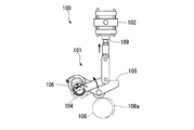
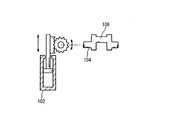
- the drive mechanism of the variable valve timing mechanism 100 described in Patent Document 4 includes a link mechanism 101 and an actuator 102 as shown in FIGS. 11A and 11B.
- the link mechanism 101 the exhaust valve swing arm 103 connected to the push rod of the engine exhaust valve is supported by the link shaft 104, and the intake valve swing arm 105 connected to the push rod of the intake valve is eccentric from the link shaft 104. It is supported by the tappet shaft 106 of the eccentric shaft portion.
- the exhaust valve swing arm 103 and the intake valve swing arm 105 can be advanced and retracted by an eccentric cam 108a of the cam shaft 108, respectively.
- the link shaft 104 is connected to a piston rod 109 provided on the actuator 102. If the position shown in FIG. 11B is before the pop-out operation of the piston rod 109, all the connected swing arms 105 and 103 are rotated to one side by the pop-out operation of the piston rod 109 by the actuator 102. Therefore, the rotation angle of all the swing arms 105 and 103 can be controlled by the actuator 102 via the link mechanism 101.
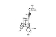
- variable valve timing mechanisms described in Patent Documents 5 and 6 are described in FIGS.
- the rotational range of the link shaft 104 is regulated by the range of the tooth portion of the sector gear 120 connected to the actuator 102, and the eccentric disk 123 eccentrically fixed to the link shaft 104 (on the tappet shaft). Is equivalent to the exhaust valve swing arm 103 and the intake valve swing arm 105.
- the position where the eccentric cam 108a of the cam shaft 108 contacts and pushes up against the exhaust valve swing arm 103 or the intake valve swing arm 105 changes with respect to the displacement of the rotational angle position of each eccentric disk 123 with respect to the rotational position of the link shaft 104. To do.
- the exhaust valve swing arm 103 and the intake valve swing arm 105 connected to the rocker arm 127 via the push rod 128 are connected to the tappet shaft 106 of the crank-shaped link shaft 104 (the fulcrum position of the swing arm). )It is connected to the.
- the actuator 102 By changing (turning) the phase of the crank-shaped link shaft 104 by the actuator 102, the fulcrum positions of the intake valve swing arm 105 and the exhaust valve swing arm 103 change, and as a result, the contact position to the camshaft 108 changes. .
- the timing at which the eccentric cam 108a of the cam shaft 108 pushes the exhaust valve swing arm 103 or the intake valve swing arm 105 with the cam shaft 108 to advance and retract is variable.
- the supercharger cannot follow and cannot supply the necessary air amount. This is because the supercharger is driven by the exhaust gas, so that it does not work effectively unless the load of the gas fuel engine increases and the exhaust gas is not sufficiently supplied to the supercharger. If the amount of air is insufficient, the air-fuel ratio becomes gas rich and knocking occurs, leading to engine failure. In order to suppress the knocking, if the load is increased at a speed that can be followed by the supercharger, it takes a long time of about 10 minutes to increase the load.
- the present invention has been made in view of the above-described problems, and provides an engine system and a control method for the engine system that can reduce the load increase time by suppressing knocking that occurs when the load of the gas fuel engine is increased.
- the purpose is to do.
- the engine system according to the present invention is an engine system including a four-stroke engine using gas as fuel, and sets a change in timing for closing the intake valve of the engine when the load on the output shaft of the engine increases. And a variable intake valve timing mechanism that changes the timing at which the intake valve closes in accordance with the intake valve close timing set by the control unit, and the variable intake valve is increased as the load on the output shaft of the engine increases. Control which lowers the compression ratio of the gas-air mixture in the engine is performed by a timing mechanism.
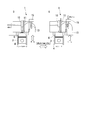
- FIG. 10A shows a normal 4-stroke cycle process
- FIG. 10B shows a mirror cycle process.
- the intake valve is normally closed at the bottom dead center of the piston (see FIG. 10A). If the closing timing is made earlier than the bottom dead center (see FIG. 10B), since the expansion of the air-fuel mixture continues even after the intake valve is closed, the in-cylinder temperature Ts is lower than in the case of FIG. 10A (Ts * ⁇ Ts).
- the timing at which the intake valve closes is advanced (advanced) from the intake bottom dead center or delayed (delayed).
- control is performed to lower the compression ratio of the air-fuel mixture in the combustion chamber of the engine.
- the temperature in the combustion chamber at the time of compression is lowered, so that knocking can be suppressed.
- the compression ratio of the air-fuel mixture is lowered in the combustion chamber, the ignitability deteriorates at the time of start-up and at a low load, and further, the fuel efficiency is deviated from a favorable condition, resulting in a demerit that fuel efficiency is deteriorated.
- the control for lowering the compression ratio at a larger rate is performed by changing the closing timing of the intake valve more greatly in the operation region where the load that is more likely to cause knocking increases.
- a torque sensor for measuring the torque of the output shaft and a rotational speed sensor for measuring the rotational speed of the output shaft are provided. Therefore, it is preferable to set a change in timing for closing the intake valve in the control unit.
- the fuel gas since the fuel gas is an elastic body, it is relatively difficult to obtain an accurate fuel supply amount as compared with the liquid fuel. Therefore, it is preferable to calculate the load in relation to the rotational speed by actually measuring the torque with a torque sensor.
- the load of the output shaft of the engine can be obtained in real time by taking the product of the rotational speed measurement value of the output shaft obtained by providing the rotational speed sensor and the torque measurement value by the torque sensor.
- variable intake valve timing mechanism may adjust the advance angle from the top dead center when the intake valve closes.
- the effect of lowering the compression ratio can be obtained regardless of whether the intake valve close timing is advanced or retarded, and can be applied to the present invention.
- the delay of the closing timing of the intake valve may be harmful due to the air-fuel mixture being blown back to the intake system, it is more desirable to set the advance timing of the closing timing of the intake valve.
- the advance angle of the closing timing of the intake valve in the variable intake valve timing mechanism may be adjusted continuously or in multiple stages. It is preferable to set the advance angle of the closing timing of the intake valve to be continuously variable or variable in accordance with the change of the load in order to suppress knocking and shorten the load increase time. .
- the advance angle determined by the control unit may be set from an advance value that is set by using the load and rotation speed data of a plurality of output shafts measured in advance as parameters.
- a suitable value for the advance angle of the closing timing of the intake valve becomes larger when the load is large, but in addition to this, it also depends on the rotational speed. Therefore, knocking can be further suppressed by creating a map including at least these two parameters in advance and controlling the advance timing of the intake valve closing timing in accordance with changes in engine load and rotational speed.
- a generator may be connected to the output shaft, and the load of the output shaft may be set by the electric power generated by the generator.
- the load of the output shaft can be obtained by obtaining the magnitude of the power generated by the connected generator using a power meter or the like.
- the engine intake pipe preferably includes a supercharger that performs supercharging and an air cooler that cools the air from the supercharger before supplying the air to the intake pipe.
- a supercharger that performs supercharging
- an air cooler that cools the air from the supercharger before supplying the air to the intake pipe.
- a supercharger is provided in the intake pipe of the engine to compensate for the decrease in the air-fuel mixture, and air can be cooled by an air cooler to suppress the rise in air temperature due to supercharging, increasing the amount of air-fuel mixture This contributes to increasing the load on the engine and can suppress knocking by reducing the temperature of the air, so that the load increase time can be shortened.
- An engine system control method is an engine system control method including an engine using gas as fuel, and sets a change in timing for closing an intake valve of the engine when the load on the output shaft of the engine increases. And a step of mechanically changing the timing at which the intake valve closes in accordance with the set timing at which the intake valve closes, and the timing at which the intake valve closes mechanically as the load on the output shaft of the engine increases.
- the compression ratio of the gas / air mixture in the engine is further lowered by changing to.
- the timing at which the intake valve closes is advanced (advanced) or delayed (retarded) from the suction bottom dead center. Then, control is performed to lower the compression ratio of the air-fuel mixture in the combustion chamber of the engine. By reducing the compression ratio, the temperature in the combustion chamber at the time of compression is lowered, so that knocking can be suppressed.
- the compression ratio of the air-fuel mixture in the engine can be lowered. You can save time.
- FIG. 1 It is a block diagram which shows the principal part structure of the marine dual fuel engine by embodiment of this invention. It is a figure which shows the diesel mode and gas mode in the dual fuel engine shown in FIG. It is a three-dimensional map which shows the relationship between load, rotation speed, and valve closing timing of an intake valve. It is a graph which shows a knocking suppression range by the relationship between load, rotation speed, and valve closing timing of an intake valve. It is a 2nd map which shows the relationship between the valve closing timing obtained by the 1st map, and the 1st electric signal. It is a flowchart which shows the change process of the intake valve opening / closing timing of the dual fuel engine shown in FIG.
- FIG. 13A It is a perspective view which shows the other example of the conventional variable intake valve timing mechanism. It is a figure which shows the further another example of the conventional variable intake valve timing mechanism. It is a figure which shows the relationship between the actuator and link shaft in the conventional variable intake valve timing mechanism shown to FIG. 13A.
- FIG. 9 shows the relationship between the angle of the crankshaft of the engine and the lift amounts of the intake valve and the exhaust valve.
- the origin of the crank angle shown on the horizontal axis is the compression top dead center, 0 to 180 degrees is the expansion stroke, 180 degrees to 360 degrees is the exhaust stroke, 360 degrees to 540 degrees is the intake stroke, 540 degrees to 720 degrees is the compression stroke It is a journey.
- the large peak in the exhaust stroke is the lift amount of the exhaust valve
- the small peak indicates the lift amount of the intake valve at high load and low load, respectively.
- the opening / closing timing of the intake valve substantially coincides with the intake stroke, starts to open around 340 degrees, and closes around 540 degrees.
- the opening / closing timing of the intake valve is controlled to advance by the VIVT mechanism.
- the closing timing of the intake valve is not controlled from the initial 545 degrees according to the load. The control is performed in stages, and the valve closing timing is controlled to be 505 degrees at a high load.
- a marine dual fuel engine 1 (hereinafter, simply referred to as an engine 1) shown in FIGS. 1 and 2 includes diesel mode D and gas mode G engines. During operation, the diesel mode D and gas mode G are provided. It is an engine that can be switched between.
- a dual fuel engine 1 shown in FIG. 1 has a mechanism of a crankshaft 2 as an output shaft connected to a propeller or the like, and the crankshaft 2 is connected to a piston 4 installed in a cylinder block 3.
- a combustion chamber 6 is formed by a piston 4 and an engine head 5 provided in the cylinder block 3.
- the combustion chamber 6 is sealed by an intake valve 8 and an exhaust valve 9 attached to the engine head 5 and a fuel injection valve 10 used in the diesel mode D.
- the engine head 5 is provided with a micro pilot oil injection valve 11 used in the gas mode.
- An intake pipe 13 is connected to the intake port where the intake valve 8 of the engine head 5 is installed, and an exhaust pipe 14 is installed to the exhaust port where the exhaust valve 9 is installed.
- An electromagnetic valve 15 that controls gas injection is installed in the intake pipe 13, and a supercharger 17 that communicates with the air cooler 16 and the exhaust pipe 14 is installed on the upstream side thereof.
- the dual fuel engine 1 can be operated by switching between the diesel mode D and the gas mode G as shown in FIG.
- the diesel mode D for example, heavy fuel oil A or the like can be mechanically injected from the fuel injection valve 10 into the compressed air in the combustion chamber 6 as fuel oil, ignited and burned.
- fuel gas such as natural gas is injected into the intake pipe 13 by the electromagnetic valve 15 and premixed with the air flow to supply the air-fuel mixture into the combustion chamber 6. Pilot fuel is injected from the pilot oil injection valve 11 to ignite and burn.
- the micro pilot oil injection valve 11 is electronically controlled, for example, and injects a small amount of pilot fuel as a powerful ignition source.
- the engine 1 is started in a diesel mode D in which liquid fuel is injected into the combustion chamber 6 from the fuel injection valve 10. After it is confirmed that the gas pressure higher than the reference value is supplied to the engine 1, the gas fuel is injected into the intake pipe 13 by the solenoid valve 15 and mixed with the air, and then flows into the combustion chamber 6. The operation is performed in the gas mode G in which the fuel is burned. When stopping, change to diesel mode D again and stop. The diesel mode D and the gas mode G can be changed except when starting and stopping .
- the dual fuel engine 1 includes a gas engine system that performs load control when the load increases in the gas mode G.
- a rotation speed sensor 20 and a torque sensor 21 are attached to the crankshaft 2.
- the rotation speed sensor 20 measures the rotation speed (rotational speed) of the crankshaft 2
- the torque sensor 21 measures the crankshaft 2.
- the torque sensor 21 for example, a sensor that detects the torque applied to the shaft by strain can be used.
- the measurement data measured by the rotation speed sensor 20 and the torque sensor 21 are output as signals to the control unit 22 that controls the engine 1.
- the control unit 22 detects the operating state of the engine 1 based on signals from the rotation speed sensor 20 and the torque sensor 21.
- a method for obtaining the load of the engine 1 a method of estimating from the fuel supply amount and other information related to the operating state of the engine 1, a torque sensor is provided in the power transmission system of the output shaft of the engine 1, and the actual torque There is a method of obtaining a load by measuring.
- the gas used as fuel is an elastic body, it is relatively difficult to obtain an accurate fuel supply amount as compared with liquid fuel. Therefore, it is preferable to calculate the load by actually measuring the torque with the torque sensor 21.
- the load A and the torque measurement value T are in a directly proportional relationship. Under the condition where the rotational speed n is constant, it is desirable to set the advance timing of the closing timing of the intake valve 8 at a larger rate as the load A is larger, that is, as the torque data T is larger.
- the control unit 22 stores a first map 24 for determining a first electric signal of intake valve opening / closing timing prepared in advance and a second map 25 for determining opening / closing timing corresponding to the first electric signal.
- the control unit 22 based on the rotational speed data n and the torque data T corresponding to the load A of the engine 1 measured by the rotational speed sensor 20 and the torque sensor 21, the control unit 22 calculates the engine 1 by the above formulas (1) and (2). The load A is calculated. Then, the first electric signal corresponding to the opening / closing timing of the intake valve 8 is selected on the first map 24 by the rotation speed n and the load A. Based on the first electric signal, the opening / closing timing of the intake valve 8 corresponding to the first electric signal is determined in the second map 25.
- the second electrical signal at the opening / closing timing set by the control unit 22 is transmitted to the electropneumatic converter 27, and the electropneumatic converter 27 converts the opening / closing timing signal into air pressure.
- This air pressure is sent to the actuator 28 to control the drive of the variable intake valve timing mechanism 30.
- the actuator 28 is supplied with air pressures P1 and P2 for driving and control from the first pressure reducing regulator 34 and the electropneumatic converter 27.
- the air pressure supplied to the actuator 28 is compressed by the air compressor 32 and stored in the air tank 33.
- the air pressure in the air tank 33 is reduced to a required pressure by the first pressure reducing regulator 34.
- the pressure at this time is adjusted by changing the valve opening degree of the first pressure-reducing regulator 34, and is supplied to the actuator 28 as the driving air pressure P1.
- the pressure P1 measured by the pressure gauge 36 is equal to or less than a specified value, the engine 1 cannot be started.
- the air pressure for driving the electropneumatic converter 27 is supplied after the pressure is further reduced from the first pressure reduction regulator 34 by the second pressure reduction regulator 37.
- the electropneumatic converter 27 supplies the air pressure corresponding to the input second electrical signal at the opening / closing timing to the actuator 28 as the air pressure P2 for adjusting the operation of the actuator 28. Based on these air pressures P1 and P2, the rod 28a of the actuator 28 is operated to operate the variable intake valve timing mechanism 30.
- the actuator 28 is, for example, a known P-cylinder (cylinder with a positioner), and controls the advance / retreat of the rod 28 a based on the pressures P 1 and P 2 input from the first pressure-reducing regulator 34 and the electropneumatic converter 27.
- the drive of the variable intake valve timing mechanism 30 is controlled, and the closing timing of the intake valve 8 is advanced (advance) or delayed (delay).
- the angle By controlling the angle, the compression ratio is lowered and control is performed. Since the time between the opening timing and the closing timing of the intake valve 8 does not change, when the opening timing advances from the suction bottom dead center, the closing timing also advances from the suction top dead center by the same time.
- the timing of valve opening and closing is changed in accordance with the load of the engine 1 to suppress knocking and shorten the load increase time.
- the opening / closing timing of the intake valve 8 is set by the first map 24 and the second map 25 in the control unit 22 based on the load A and the rotational speed n of the engine 1, and the intake valve 8 is controlled by the actuator 28 and the variable intake valve timing mechanism 30.
- the valve opening and closing timing is adjusted so that knocking can be suppressed.
- variable intake valve timing mechanism 30 has a structure similar to that shown in FIGS. That is, in the variable intake valve timing mechanism 30, for example, a link shaft whose rotation angle range is set via a sector gear according to the moving length of the rod 28a of the actuator 28 and a cam shaft having an eccentric cam are arranged in parallel. Yes.
- An exhaust swing arm is connected to the link shaft, and an intake swing arm is connected to a tappet shaft provided at an eccentric position of the link shaft.
- An intake valve 8 is connected to the intake swing arm via a push rod and a rocker arm, and an exhaust valve 9 is connected to the exhaust swing arm via a push rod and a rocker arm.
- the distance between the cam shaft and the intake swing arm changes depending on the rotation angle of the tappet shaft according to the rotation of the link shaft, and the timing at which the eccentric cam of the cam shaft starts to change changes.
- the valve closing timing can be changed to an advance angle (or a delay angle).
- the rotation angle of the tappet shaft is changed by the moving length of the rod 28a of the actuator 28.
- the moving length of the rod 28 a is arbitrarily changed by the control air pressures P 1 and P 2 supplied to the actuator 28.
- the magnitude of the advance angle, which is the closing timing of the intake valve 8 is determined by the timing at which the eccentric cam of the cam shaft starts to hit the intake swing arm connected to the tappet shaft of the link shaft.
- the tappet shaft rotating device in the variable intake valve timing mechanism 30 may use a servo motor (not shown) instead of the actuator 28.
- a signal of the opening / closing timing transmitted from the second map 25 of the control unit 22 is input to the servo motor.
- the servo motor can change the opening / closing timing of the intake valve 8 by rotating the link shaft by an amount corresponding to the received signal and rotating the tappet shaft so as to approach and separate from the cam shaft.
- the configuration from the actuator 28 and the air compressor 32 to the pressure gauge 38 is not necessary. Further, the servo motor is driven by a controller instead of the electropneumatic converter 27.
- gas fuel is supplied to a gas vaporizer 41 from an LNG gas tank 40 in which gas fuel such as natural gas is stored, and the gas pressure is reduced to a necessary gas pressure by a gas regulator 42.
- the pressure at this time is displayed on the pressure gauge 43, adjusted by changing the valve opening of the gas regulator 42, and injected from the electromagnetic valve 15 into the intake pipe 13 as gas fuel for combustion.
- the gas fuel and supercharged air cooled by the air cooler 16 are mixed and supplied to the combustion chamber 6.
- the supply amount of the gas fuel is increased by the operation of the electromagnetic valve 15.
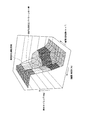
- FIG. 3 is a three-dimensional map showing details of the first map 24 for determining the closing timing of the intake valve 8 based on the rotation speed n of the crankshaft 2 and the load A of the engine 1.
- the first map 24 was created based on the steps of the following experimental procedures (1) to (18). In the experiment, a dual fuel engine 1 of the same model that was actually used was used. (1) The engine 1 is started, the rotational speed n is set to 400 min ⁇ 1 , the load A is set to 10%, and the closing timing of the intake valve 8 is set to 545 deg (the latest closing timing in terms of structure).
- knocking abnormal combustion called knocking that occurs when the engine 1 is driven and the exhaust temperature at that time are measured. Knocking is detected by a knock sensor (not shown) attached to each engine head 5. When knocking occurs, the normal combustion waveform is superimposed on the high-frequency pressure fluctuation.
- the exhaust temperature at the time of knocking measurement is measured by a temperature sensor attached to the exhaust pipe 14.
- the closing timing of the intake valve 8 is decreased by 5 degrees, and the measurement of (2) is performed again. Measurement is performed by changing the valve closing timing to 500 deg (the earliest valve closing timing in terms of structure).
- the load is increased stepwise by 10% until it reaches 110%, and the measurements in (2) and (3) are repeated again.
- FIG. 4 is a graph showing the measurement result of (7) above with three axes of the rotation speed n, the load A, and the opening / closing timing.
- a range surrounded by a straight line is a range where knocking is suppressed and the engine 1 can be operated safely.
- NOx nitrogen oxides
- FIG. 4 Next, nitrogen oxides (hereinafter referred to as NOx) are within a three-dimensional region surrounded by a straight line shown in FIG. 4 that can be operated safely, as measured by the experiments (1) to (8). Further experiments are conducted to find a setting that is below the reference value and has the highest thermal efficiency.
- the engine speed n is set to 400 min ⁇ 1
- the load A is set to 10%
- the valve closing timing of the intake valve 8 is set to 545 deg.
- knocking is detected by increasing the rotational speed n and the load A in an arbitrary load increasing pattern.
- the load increasing pattern is a change state per time of the load A and the rotation speed n, and changes depending on the propeller specifications (shape, rotation speed) of the marine propulsion device.
- the valve closing timing of the measurement point where the knocking strength detected in (15) is equal to or greater than the reference value is decreased by 3 degrees.
- the steps (15) and (16) are repeated until the knocking strength is equal to or less than the reference value, and the valve closing timing at which knocking is suppressed is determined. If the valve closing timing is decreased, the thermal efficiency deteriorates.
- the setting of the valve closing timing at which NOx and the knocking strength are equal to or less than the reference values and the highest thermal efficiency is obtained is set as the setting value of the rotation speed n and the load A.
- the valve closing timing at which knocking was suppressed from the above (17) was measured at each rotation speed n and load A, and the final first map 24 shown in FIG.
- valve closing timing according to the rotation speed n and the load A is shown in a three-dimensional graph, and the upper side in the figure is the direction in which the valve closing timing is further decreased (large advance angle).
- a region indicated by a two-dot chain line on a three-dimensional plane is a practical operation region used in the operation of an actual ship propulsion apparatus, and an example of a good load increase pattern is indicated by a one-dot chain line.
- control is performed to increase the advance angle of the valve closing timing as the engine load increases.
- the advance angle is minimized at the lower right position in the figure where the rotation speed n and the load A are small, and the advance angle increases as the rotation speed n and the load A increase. To do. There is a region where the advance angle is constant in the middle, but the advance angle is increased as the load increases as a whole. Since the load is obtained by the product of the torque and the rotational speed, it can be expressed that the advance angle increases as the torque of the output shaft increases.
- the second map 25 was created by the following experiment.
- the variable intake valve timing mechanism 30 is rotationally controlled by the actuator 28, the second map 25 is created by the following procedure.
- (1) The valve closing timing is changed by the actuator 28, and the pressure when changing to each valve closing timing is measured.
- (2) Based on the specifications of the electropneumatic converter 27, the second electrical signal necessary for supplying the pressure (1) is investigated.
- (3) From the results of (1) and (2) above, the first electric signal selected on the first map 24 on the horizontal axis and the second map 25 indicating the valve closing timing (second electric signal) on the vertical axis. create.
- the above description is for the case where the actuator 28 is used.
- the variable intake valve timing mechanism 30 is controlled to rotate by a servo motor instead of the actuator 28, the following description is given.
- the valve closing timing is changed based on the servo motor, and the second electric signal when changing to each valve closing timing is measured.
- a second map 25 is created that indicates the first electric signal on the horizontal axis and the valve closing timing (second electric signal) on the vertical axis.
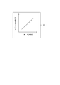
- FIG. 5 shows a detailed view of the second map 25.
- the second map 25 is a map representing the relationship between the valve closing timing (second electric signal) and the first electric signal.
- the load increasing device of the dual fuel engine 1 has the above-described configuration. Next, a load increasing method will be described.
- the air supplied from the supercharger 17 is premixed with the gas fuel injected from the electromagnetic valve 15 while being cooled by the air cooler 16 and supplied into the combustion chamber 6 in the cylinder block 3.
- the In the intake process the intake valve 8 is closed before the piston 4 reaches bottom dead center, and the piston 4 is further lowered, so that the air-fuel mixture in the combustion chamber 6 becomes negative pressure, and the temperature and compression ratio of the air-fuel mixture are reduced. Go down. Thereby, knocking can be suppressed.
- the piston 4 In the compression process, the air-fuel mixture in the combustion chamber 6 is compressed by the piston 4, fuel is injected from the micropilot oil injection valve 11 in the expansion stroke and ignited, the combustion gas expands and pushes the piston 4 to the bottom dead center, In the exhaust process, the piston 4 rises to the top dead center and exhausts the combustion gas.
- Such a control method of the gas mode G will be described along a flowchart of a method for changing the opening / closing timing of the intake valve 8 shown in FIG.
- Whether or not the required pressure P1 is supplied to the actuator 28 when the engine 1 is started is measured by the pressure gauge 36. If this value is equal to or less than a specified value, the engine 1 cannot be started. Further, when the main pressure P1 becomes a specified value or less during engine operation, the engine 1 is stopped.
- the control of the opening / closing timing of the intake valve 8 is started when the intake valve 8 is started regardless of the operation mode of the engine 1.
- the start timing is determined to have been started when a measured value signal of the rotation speed n is input from the rotation speed sensor 20 to the control unit 22.
- the state of the engine 1 is detected at predetermined intervals.
- the detected rotation speed n and torque T are input into the control unit 22 and the load A is calculated by the above equations (1) and (2).
- the rotation speed n and the measured value of the load A are input to the first map 24 for determining the intake valve opening / closing timing.
- the intake valve opening / closing timing corresponding to the input load A and the rotational speed n is determined and output as a first electric signal.
- the first electric signal is input to the second map 25, the opening / closing timing corresponding to the first electric signal is set, the second electric signal corresponding to the opening / closing timing is determined by the second map 25, and the electropneumatic converter 27 is determined.
- the opening / closing timing is set as an advance angle of the opening timing and closing timing of the intake valve 8 from the intake bottom dead center and the intake top dead center of the piston 4.
- Adjustment of the advance angle of the closing timing and opening timing of the intake valve 8 in the variable intake valve timing mechanism 30 is performed so as to change continuously or in multiple stages according to the rotational speed n of the engine 1 and the load A.
- the advance angle of the timing of closing and opening the intake valve 8 can be made in two stages of “1” with advance and “0” without advance, but the number of revolutions n and load A are used as parameters.
- the control air pressure P2 corresponding to the input second electric signal is supplied to the actuator 28.
- the moving length of the rod 28a of the actuator 28 is changed by the control air pressure P2 supplied to the actuator 28, and the tappet shaft of the variable intake valve timing mechanism 30 is rotated by a required angle.
- the moving length of the rod 28a varies depending on the amount of control air pressure P2 supplied to the actuator 28.
- the variable intake valve timing mechanism 30 the distance between the intake valve swing arm connected to the tappet shaft and the cam shaft is changed by the rotation of the tappet shaft, and the timing at which the eccentric cam provided on the cam shaft starts to change changes. From this change, the opening / closing timing of the intake valve 8 when the load is increased changes. Knocking can be suppressed by changing the opening / closing timing of the intake valve 8.
- the intake valve 8 can detect the state of the engine 1 at the time of increasing the load at predetermined intervals based on the load A and the rotation speed n, and can suppress knocking by the first map 24 and the second map 25 of the control unit 22.
- the opening / closing timing of the intake valve 8 is advanced by the actuator 28 and the variable intake valve timing mechanism 30 to suppress knocking, thereby shortening the load increase time.
- FIG. 7 shows a flowchart in the case where the rotation of the tappet shaft is controlled using a servo motor instead of the electropneumatic converter 27 and the actuator 28.
- the engine speed is increased from the first map 24 and the second map 25 by inputting the measured values of the rotational speed n and the torque T detected at predetermined intervals to the control unit 22.
- the opening / closing timing of the intake valve 8 according to the state is sequentially selected.
- the second electric signal transmitted from the second map 25 is input to the servo motor via the controller.
- the servo motor calculates the rotational position corresponding to the input second electrical signal, rotates the tappet shaft by rotating the link shaft by the required angle, and changes the opening / closing timing of the intake valve 8 from the bottom dead center and top dead center To do.
- the load increase response test in the gas mode G was performed on the dual fuel engine 1 according to the embodiment of the present invention.
- the air temperature was set to 18 ° C, 25 ° C, 36 ° C, and 37 ° C.
- the engine speed n, torque T, and elapsed time were measured at predetermined intervals from the start of load increase in the idle rotation state until the rated load (rated rotation) was reached.
- the result was as shown in FIG.
- the temperatures were 18 ° C, 25 ° C, 36 ° C, and 37 ° C. In either case, the rated load was reached in about 20 seconds. For this reason, the load raising speed can be remarkably improved.
- the diesel mode D is switched to the gas mode G, and the first is based on the engine speed n and the torque T measured at predetermined intervals.
- the load increase time can be shortened by sequentially advancing the opening / closing timing of the intake valve 8 so as to suppress knocking by the map 24 and the second map 25.
- the opening / closing timing is selected within the range of the three-dimensional map shown in FIG. 4, the generation of NOx can be reduced.
- the efficiency at low load can be improved by optimizing the opening / closing timing of the intake valve 8.
- gas system according to the present invention is not limited to the dual fuel engine 1 according to the above-described embodiment, and can be appropriately changed or replaced without departing from the gist of the present invention.
- modifications and the like of the present invention will be described, but the same or similar parts and components as those described in the above-described embodiments will be described using the same reference numerals.
- the gas system according to the present invention is not limited to the dual fuel engine 1 capable of switching between the diesel mode D in which liquid fuel is the main fuel and the gas mode G in which gas is the main fuel, and uses gas as the fuel. It can also be applied to gas engines. In that case, it is applicable also to the generator which uses gas as the main fuel. In this case, a generator may be connected to the output shaft instead of the torque sensor, and the load on the output shaft may be measured by the electric power generated by the generator.
- the present invention is not limited to the load increase pattern of the marine engine, but can be applied to a load increase pattern that can be used in a vehicle or an emergency generator.
- the change of the valve opening timing and the valve closing timing of the intake valve 8 at the time of increasing the load is set by the advance angle from the intake bottom dead center and the intake top dead center of the piston 4. Without being limited to the advance angle, it may be set with a retard angle. The effect of lowering the compression ratio of the air-fuel mixture can be obtained regardless of whether the operation is advanced or retarded. However, since the delay of the timing for closing the intake valve 8 may be harmful due to the air-fuel mixture being blown back to the intake system, the advance timing of the opening / closing timing of the intake valve 8 may be applied to an actual engine 1. It is more desirable to adopt.
- the variable intake valve timing mechanism 30 changes both the valve opening timing and the valve closing timing and does not change the time during which the intake valve is open. One or both of the valve opening timings may be selected and changed.
- the present invention provides a gas system that uses a premixed gas fuel and air to suppress knocking at the time of load increase and shorten the load increase time, and a control method therefor.
Landscapes
- Engineering & Computer Science (AREA)
- Chemical & Material Sciences (AREA)
- Combustion & Propulsion (AREA)
- Mechanical Engineering (AREA)
- General Engineering & Computer Science (AREA)
- Oil, Petroleum & Natural Gas (AREA)
- Output Control And Ontrol Of Special Type Engine (AREA)
- Supercharger (AREA)
- Combined Controls Of Internal Combustion Engines (AREA)
Abstract
Priority Applications (4)
| Application Number | Priority Date | Filing Date | Title |
|---|---|---|---|
| EP16894300.9A EP3431740B1 (fr) | 2016-03-14 | 2016-03-14 | Système moteur et son procédé de commande |
| PCT/JP2016/057955 WO2017158676A1 (fr) | 2016-03-14 | 2016-03-14 | Système moteur et son procédé de commande |
| JP2017548233A JP6416410B2 (ja) | 2016-03-14 | 2016-03-14 | エンジンシステムとその制御方法 |
| CN201680082597.6A CN108699971B (zh) | 2016-03-14 | 2016-03-14 | 发动机系统及其控制方法 |
Applications Claiming Priority (1)
| Application Number | Priority Date | Filing Date | Title |
|---|---|---|---|
| PCT/JP2016/057955 WO2017158676A1 (fr) | 2016-03-14 | 2016-03-14 | Système moteur et son procédé de commande |
Publications (1)
| Publication Number | Publication Date |
|---|---|
| WO2017158676A1 true WO2017158676A1 (fr) | 2017-09-21 |
Family
ID=59851679
Family Applications (1)
| Application Number | Title | Priority Date | Filing Date |
|---|---|---|---|
| PCT/JP2016/057955 Ceased WO2017158676A1 (fr) | 2016-03-14 | 2016-03-14 | Système moteur et son procédé de commande |
Country Status (4)
| Country | Link |
|---|---|
| EP (1) | EP3431740B1 (fr) |
| JP (1) | JP6416410B2 (fr) |
| CN (1) | CN108699971B (fr) |
| WO (1) | WO2017158676A1 (fr) |
Cited By (2)
| Publication number | Priority date | Publication date | Assignee | Title |
|---|---|---|---|---|
| CN115135863A (zh) * | 2019-12-20 | 2022-09-30 | 涡轮增压系统瑞士有限公司 | 具有定量混合物控制装置的内燃机的混合物供应系统 |
| KR20230001947A (ko) * | 2021-06-29 | 2023-01-05 | 한국과학기술원 | 이종연료 예혼합압축착화식 엔진 및 이를 제어하는 방법 |
Families Citing this family (3)
| Publication number | Priority date | Publication date | Assignee | Title |
|---|---|---|---|---|
| GB2583912A (en) * | 2019-05-06 | 2020-11-18 | Caterpillar Motoren Gmbh & Co | Charge changing control device, reciprocating engine and method for operating a charge changing control device |
| CN114934846B (zh) * | 2022-05-26 | 2023-07-25 | 一汽解放汽车有限公司 | 引燃油控制提前角的控制方法、装置、设备及存储介质 |
| CN120140075A (zh) * | 2025-03-12 | 2025-06-13 | 潍柴动力股份有限公司 | 控制燃气喷射的方法、装置和计算机可读存储介质 |
Citations (11)
| Publication number | Priority date | Publication date | Assignee | Title |
|---|---|---|---|---|
| JPS6299606A (ja) | 1985-10-28 | 1987-05-09 | Hino Motors Ltd | 内燃機関の可変バルブタイミング装置 |
| JPH07259655A (ja) * | 1994-03-23 | 1995-10-09 | Komatsu Ltd | 排気還流装置 |
| JP2002021608A (ja) * | 2000-07-05 | 2002-01-23 | Osaka Gas Co Ltd | 予混合圧縮自着火エンジン |
| JP4137704B2 (ja) | 2003-06-04 | 2008-08-20 | 本田技研工業株式会社 | 内燃機関の制御装置 |
| JP2008202545A (ja) | 2007-02-21 | 2008-09-04 | Mitsubishi Heavy Ind Ltd | デュアルフュールエンジン |
| JP2009057958A (ja) * | 2007-08-06 | 2009-03-19 | Nissan Motor Co Ltd | エンジン |
| JP4367532B2 (ja) | 2007-06-08 | 2009-11-18 | トヨタ自動車株式会社 | 内燃機関の制御装置 |
| EP2136054A1 (fr) | 2008-06-18 | 2009-12-23 | Caterpillar Motoren GmbH & Co. KG | Procédé et dispositif pour contrôler le fonctionnement d'un moteur à combustion interne |
| JP2013185515A (ja) * | 2012-03-08 | 2013-09-19 | Yanmar Co Ltd | 副室式ガスエンジン |
| JP2015048790A (ja) * | 2013-09-02 | 2015-03-16 | 株式会社日本自動車部品総合研究所 | エンジン制御装置 |
| WO2015060117A1 (fr) | 2013-10-25 | 2015-04-30 | ヤンマー株式会社 | Mécanisme de calage de distribution variable et moteur à mécanisme de calage de distribution variable |
Family Cites Families (14)
| Publication number | Priority date | Publication date | Assignee | Title |
|---|---|---|---|---|
| SE512943C2 (sv) * | 1998-10-05 | 2000-06-12 | Saab Automobile | Förbränningsmotor |
| US6230683B1 (en) * | 1997-08-22 | 2001-05-15 | Cummins Engine Company, Inc. | Premixed charge compression ignition engine with optimal combustion control |
| EP0928369B1 (fr) * | 1996-08-23 | 2006-05-10 | Cummins Inc. | Moteur a allumage par compression d'une charge premelangee avec regulation optimale de la combustion |
| JPH10141068A (ja) * | 1996-11-01 | 1998-05-26 | Yanmar Diesel Engine Co Ltd | ミラーサイクルエンジンの給気冷却構造 |
| AU2001261245A1 (en) * | 2000-05-08 | 2001-11-20 | Cummins, Inc. | Multiple operating mode engine and method of operation |
| ATE440210T1 (de) * | 2001-12-25 | 2009-09-15 | Niigata Power Systems Co Ltd | Zweistoffmotor |
| DE102004026157B4 (de) * | 2003-05-30 | 2017-11-09 | Honda Motor Co., Ltd. | Ventilzeitsteuerungs-Steuer-/Regelsystem und Steuer-/Regelsystem für einen Verbrennungsmotor |
| US7597072B2 (en) * | 2006-10-24 | 2009-10-06 | Ford Global Technologies, Llc | System and method for operating a multiple fuel engine |
| JP4656052B2 (ja) * | 2006-12-21 | 2011-03-23 | トヨタ自動車株式会社 | 内燃機関のバルブ特性制御装置 |
| JP4512617B2 (ja) * | 2007-06-26 | 2010-07-28 | 日立オートモティブシステムズ株式会社 | 内燃機関の制御装置および方法 |
| CN102301110B (zh) * | 2009-02-12 | 2014-06-11 | 丰田自动车株式会社 | 火花点火式内燃机 |
| JP5185910B2 (ja) * | 2009-10-16 | 2013-04-17 | 三菱重工業株式会社 | ミラーサイクルエンジン |
| CN102022154A (zh) * | 2011-01-13 | 2011-04-20 | 大连理工大学 | 内燃机进排气门控制方法 |
| EP2837804A1 (fr) * | 2013-08-13 | 2015-02-18 | Caterpillar Motoren GmbH & Co. KG | Moteurs à combustion interne en fonctionnement |
-
2016
- 2016-03-14 WO PCT/JP2016/057955 patent/WO2017158676A1/fr not_active Ceased
- 2016-03-14 JP JP2017548233A patent/JP6416410B2/ja active Active
- 2016-03-14 EP EP16894300.9A patent/EP3431740B1/fr active Active
- 2016-03-14 CN CN201680082597.6A patent/CN108699971B/zh active Active
Patent Citations (11)
| Publication number | Priority date | Publication date | Assignee | Title |
|---|---|---|---|---|
| JPS6299606A (ja) | 1985-10-28 | 1987-05-09 | Hino Motors Ltd | 内燃機関の可変バルブタイミング装置 |
| JPH07259655A (ja) * | 1994-03-23 | 1995-10-09 | Komatsu Ltd | 排気還流装置 |
| JP2002021608A (ja) * | 2000-07-05 | 2002-01-23 | Osaka Gas Co Ltd | 予混合圧縮自着火エンジン |
| JP4137704B2 (ja) | 2003-06-04 | 2008-08-20 | 本田技研工業株式会社 | 内燃機関の制御装置 |
| JP2008202545A (ja) | 2007-02-21 | 2008-09-04 | Mitsubishi Heavy Ind Ltd | デュアルフュールエンジン |
| JP4367532B2 (ja) | 2007-06-08 | 2009-11-18 | トヨタ自動車株式会社 | 内燃機関の制御装置 |
| JP2009057958A (ja) * | 2007-08-06 | 2009-03-19 | Nissan Motor Co Ltd | エンジン |
| EP2136054A1 (fr) | 2008-06-18 | 2009-12-23 | Caterpillar Motoren GmbH & Co. KG | Procédé et dispositif pour contrôler le fonctionnement d'un moteur à combustion interne |
| JP2013185515A (ja) * | 2012-03-08 | 2013-09-19 | Yanmar Co Ltd | 副室式ガスエンジン |
| JP2015048790A (ja) * | 2013-09-02 | 2015-03-16 | 株式会社日本自動車部品総合研究所 | エンジン制御装置 |
| WO2015060117A1 (fr) | 2013-10-25 | 2015-04-30 | ヤンマー株式会社 | Mécanisme de calage de distribution variable et moteur à mécanisme de calage de distribution variable |
Non-Patent Citations (1)
| Title |
|---|
| See also references of EP3431740A4 * |
Cited By (3)
| Publication number | Priority date | Publication date | Assignee | Title |
|---|---|---|---|---|
| CN115135863A (zh) * | 2019-12-20 | 2022-09-30 | 涡轮增压系统瑞士有限公司 | 具有定量混合物控制装置的内燃机的混合物供应系统 |
| KR20230001947A (ko) * | 2021-06-29 | 2023-01-05 | 한국과학기술원 | 이종연료 예혼합압축착화식 엔진 및 이를 제어하는 방법 |
| KR102510053B1 (ko) | 2021-06-29 | 2023-03-15 | 한국과학기술원 | 이종연료 예혼합압축착화식 엔진 및 이를 제어하는 방법 |
Also Published As
| Publication number | Publication date |
|---|---|
| EP3431740A4 (fr) | 2019-10-09 |
| EP3431740B1 (fr) | 2026-05-06 |
| CN108699971B (zh) | 2021-10-26 |
| JP6416410B2 (ja) | 2018-10-31 |
| EP3431740A1 (fr) | 2019-01-23 |
| JPWO2017158676A1 (ja) | 2018-03-22 |
| CN108699971A (zh) | 2018-10-23 |
Similar Documents
| Publication | Publication Date | Title |
|---|---|---|
| CN102124208B (zh) | 燃气发动机的爆震控制装置 | |
| JP6416410B2 (ja) | エンジンシステムとその制御方法 | |
| US11125180B2 (en) | Auto-ignition control in a combustion engine | |
| KR101137743B1 (ko) | 예비 혼합 압축 자착화 연소 기관의 제어 장치 | |
| EP1777398A2 (fr) | Commande variable de soupapes pour un moteur à combustion interne | |
| EP2357345A2 (fr) | Procédé et appareil de contrôle de moteur suralimenté pendant la combustion par auto-allumage par compression | |
| CN109415986B (zh) | 内燃机的控制装置以及内燃机的控制方法 | |
| US20210239068A1 (en) | Control apparatus for compression-ignition type engine | |
| US11313269B2 (en) | Control apparatus for compression-ignition type engine | |
| US11111871B2 (en) | Control apparatus for compression-ignition type engine | |
| WO2018012309A1 (fr) | Dispositif et procédé de commande destinés à un moteur à combustion interne | |
| US11105255B2 (en) | Control apparatus for compression-ignition type engine | |
| US11199152B2 (en) | Control apparatus for compression-ignition type engine | |
| JP6793824B2 (ja) | エンジンの制御方法及びエンジンシステム | |
| JP6831901B2 (ja) | エンジンシステムとその制御方法 | |
| EP3421777B1 (fr) | Appareil de commande de moteur à combustion interne | |
| WO2023079799A1 (fr) | Appareil de commande de moteur et procédé de commande de moteur | |
| JP6640950B2 (ja) | エンジンシステムとその制御方法 | |
| CN111094726B (zh) | 发动机的运转方法及发动机系统 | |
| CN102741533B (zh) | 内燃机的燃烧控制装置 | |
| JP2010159683A (ja) | 内燃機関 | |
| JP2010013940A (ja) | 内燃機関及びバルブタイミング制御方法 | |
| JP2005083284A (ja) | 内燃機関の燃料噴射制御装置 | |
| JP2022094005A (ja) | 内燃機関の制御装置 |
Legal Events
| Date | Code | Title | Description |
|---|---|---|---|
| ENP | Entry into the national phase |
Ref document number: 2017548233 Country of ref document: JP Kind code of ref document: A |
|
| NENP | Non-entry into the national phase |
Ref country code: DE |
|
| WWE | Wipo information: entry into national phase |
Ref document number: 2016894300 Country of ref document: EP |
|
| ENP | Entry into the national phase |
Ref document number: 2016894300 Country of ref document: EP Effective date: 20181015 |
|
| 121 | Ep: the epo has been informed by wipo that ep was designated in this application |
Ref document number: 16894300 Country of ref document: EP Kind code of ref document: A1 |