WO2017158801A1 - Emballage et ensemble emballage - Google Patents
Emballage et ensemble emballage Download PDFInfo
- Publication number
- WO2017158801A1 WO2017158801A1 PCT/JP2016/058570 JP2016058570W WO2017158801A1 WO 2017158801 A1 WO2017158801 A1 WO 2017158801A1 JP 2016058570 W JP2016058570 W JP 2016058570W WO 2017158801 A1 WO2017158801 A1 WO 2017158801A1
- Authority
- WO
- WIPO (PCT)
- Prior art keywords
- cap
- storage space
- liquid injection
- injection tool
- liquid
- Prior art date
- Legal status (The legal status is an assumption and is not a legal conclusion. Google has not performed a legal analysis and makes no representation as to the accuracy of the status listed.)
- Ceased
Links
Images



Classifications
-
- A—HUMAN NECESSITIES
- A61—MEDICAL OR VETERINARY SCIENCE; HYGIENE
- A61M—DEVICES FOR INTRODUCING MEDIA INTO, OR ONTO, THE BODY; DEVICES FOR TRANSDUCING BODY MEDIA OR FOR TAKING MEDIA FROM THE BODY; DEVICES FOR PRODUCING OR ENDING SLEEP OR STUPOR
- A61M5/00—Devices for bringing media into the body in a subcutaneous, intra-vascular or intramuscular way; Accessories therefor, e.g. filling or cleaning devices, arm-rests
-
- A—HUMAN NECESSITIES
- A61—MEDICAL OR VETERINARY SCIENCE; HYGIENE
- A61M—DEVICES FOR INTRODUCING MEDIA INTO, OR ONTO, THE BODY; DEVICES FOR TRANSDUCING BODY MEDIA OR FOR TAKING MEDIA FROM THE BODY; DEVICES FOR PRODUCING OR ENDING SLEEP OR STUPOR
- A61M5/00—Devices for bringing media into the body in a subcutaneous, intra-vascular or intramuscular way; Accessories therefor, e.g. filling or cleaning devices, arm-rests
- A61M5/178—Syringes
- A61M5/31—Details
- A61M5/32—Needles; Details of needles pertaining to their connection with syringe or hub; Accessories for bringing the needle into, or holding the needle on, the body; Devices for protection of needles
-
- B—PERFORMING OPERATIONS; TRANSPORTING
- B65—CONVEYING; PACKING; STORING; HANDLING THIN OR FILAMENTARY MATERIAL
- B65D—CONTAINERS FOR STORAGE OR TRANSPORT OF ARTICLES OR MATERIALS, e.g. BAGS, BARRELS, BOTTLES, BOXES, CANS, CARTONS, CRATES, DRUMS, JARS, TANKS, HOPPERS, FORWARDING CONTAINERS; ACCESSORIES, CLOSURES, OR FITTINGS THEREFOR; PACKAGING ELEMENTS; PACKAGES
- B65D75/00—Packages comprising articles or materials partially or wholly enclosed in strips, sheets, blanks, tubes or webs of flexible sheet material, e.g. in folded wrappers
- B65D75/28—Articles or materials wholly enclosed in composite wrappers, i.e. wrappers formed by associating or interconnecting two or more sheets or blanks
- B65D75/30—Articles or materials enclosed between two opposed sheets or blanks having their margins united, e.g. by pressure-sensitive adhesive, crimping, heat-sealing, or welding
- B65D75/32—Articles or materials enclosed between two opposed sheets or blanks having their margins united, e.g. by pressure-sensitive adhesive, crimping, heat-sealing, or welding one or both sheets or blanks being recessed to accommodate contents
- B65D75/36—Articles or materials enclosed between two opposed sheets or blanks having their margins united, e.g. by pressure-sensitive adhesive, crimping, heat-sealing, or welding one or both sheets or blanks being recessed to accommodate contents one sheet or blank being recessed and the other formed of relatively stiff flat sheet material, e.g. blister packages, the recess or recesses being preformed
-
- B—PERFORMING OPERATIONS; TRANSPORTING
- B65—CONVEYING; PACKING; STORING; HANDLING THIN OR FILAMENTARY MATERIAL
- B65D—CONTAINERS FOR STORAGE OR TRANSPORT OF ARTICLES OR MATERIALS, e.g. BAGS, BARRELS, BOTTLES, BOXES, CANS, CARTONS, CRATES, DRUMS, JARS, TANKS, HOPPERS, FORWARDING CONTAINERS; ACCESSORIES, CLOSURES, OR FITTINGS THEREFOR; PACKAGING ELEMENTS; PACKAGES
- B65D81/00—Containers, packaging elements, or packages, for contents presenting particular transport or storage problems, or adapted to be used for non-packaging purposes after removal of contents
- B65D81/24—Adaptations for preventing deterioration or decay of contents; Applications to the container or packaging material of food preservatives, fungicides, pesticides or animal repellants
Definitions
- the present invention relates to a package and a package assembly.
- a liquid injector such as an autoinjector configured such that when a drug solution is administered to a living body, the plunger is pressed in the distal direction by the urging force of a coil spring, and the plunger is automatically moved in the distal direction (for example, , See Patent Document 1).
- a cap is detachably attached to the distal end portion of the liquid injection tool, so that the hollow needle of the liquid injection tool can be protected, and erroneous puncture by the hollow needle can be prevented.
- a drug solution can be easily and reliably administered even to a person who has a weak grip, such as an elderly person, or a person who has difficulty in fingers such as a rheumatic patient.
- Such a liquid injection tool is stored in, for example, a blister package described in Patent Document 2.
- a liquid injection tool can be protected at the time of transport, the water
- the liquid injection tool is taken out of the package, and the cap attached to the tip is picked and removed by fingers.
- the object of the present invention is to easily remove the cap of the liquid injector when using a stored liquid injector such as an autoinjector, and to omit the operation of picking and removing the cap with fingers. It is an object of the present invention to provide a package and a package assembly that can be used.
- a main body having a body that can be filled with a liquid and a syringe provided with a needle attached to the tip of the body to discharge the liquid, and a cylindrical cap that covers the needle
- a packaging body for storing a liquid injection tool provided with a stepped portion between an outer peripheral surface of the cap or the main body portion and the cap, A bottom, a side wall extending upward from the periphery of the bottom, an opening surrounded by an upper end of the side wall, and a storage space for storing the liquid injector formed by the bottom and the side wall.
- a container having The storage space has a cap storage space for storing the cap of the liquid injection tool stored in the storage space;
- An engagement portion that engages with the step portion to remove the cap from the liquid injection tool is formed in the cap storage space, When the liquid injection tool is taken out from the storage space through the opening, the syringe shaft and the cap shaft substantially coincide with the engaging portion engaged with the stepped portion of the cap.
- a packaging body characterized in that the base end portion of the liquid injection tool can be protruded from the opening portion.
- the engaging portion is not engaged with the stepped portion when the liquid injection tool is stored in the storage space, and at least the stepped portion of the cap is stored in the cap storing space.
- the engagement portion includes the first protrusion protruding from the bottom toward the cap storage space, and the cap storage from the side wall facing the tip of the cap stored in the cap storage space.
- the liquid injector has an elongated shape,
- the opening has a longitudinal shape
- the container is a plane viewed from a direction perpendicular to the bottom so that the liquid injector can be stored in the storage space with the axis of the liquid injector approximately parallel to the longitudinal direction of the opening.
- a shape having a major axis and a minor axis in view, Said 1st protrusion part and said 2nd protrusion part are the packaging bodies as described in said (4) arrange
- the cap when removing the cap from the liquid injector such as an auto injector, the cap can be easily and reliably removed by engaging the step portion of the cap with the engaging portion of the package.
- the cap when taking out the liquid administration device from the package storage space, the cap can be removed by engaging the engaging portion of the package with the stepped portion of the cap, and the operation of picking and removing the cap with fingers is omitted. can do. That is, the operation of taking out the liquid administration tool from the storage space of the package and removing the cap can be performed in one step, and the operation can be simplified.
- the liquid administration device is removed from the storage space of the package.
- the cap When removing the cap while taking out, it is possible to prevent the needle from being bent.
- the engaging portion is formed in the cap storage space, when the cap is removed from the liquid injection tool, the cap is stored in the cap storage space, so that the cap does not roll and is easily discarded. .
- FIG. 1 is a perspective view showing an embodiment of the packaging assembly of the present invention.
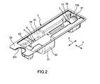
- FIG. 2 is a perspective view showing a state where the sealing member of the packaging assembly shown in FIG. 1 is peeled off.
- FIG. 3 is a cross-sectional view for explaining an operation procedure when the cap of the packaging assembly shown in FIG. 1 is removed.
- FIG. 4 is a cross-sectional view for explaining an operation procedure when the cap of the packaging assembly shown in FIG. 1 is removed.
- FIG. 5 is a cross-sectional view for explaining an operation procedure when the cap of the packaging assembly shown in FIG. 1 is removed.
- FIG. 1 is a perspective view showing an embodiment of the packaging assembly of the present invention.
- FIG. 2 is a perspective view showing a state where the sealing member of the packaging assembly shown in FIG. 1 is peeled off.
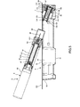
- 3 to 5 are cross-sectional views for explaining an operation procedure when removing the cap of the packaging assembly shown in FIG.
- FIGS. 1 to 5 the upper side in FIGS. 1 to 5 is “upper” or “upper”, the lower side is “lower” or “lower”, the right side is “right”, and the left side is “left”.
- the left side of the liquid injection tool in FIG. 3 to 5 illustration of the pusher and the second coil spring is omitted.
- the packaging assembly 1 includes a liquid injection tool 5 and a packaging body 2 that houses the liquid injection tool 5.
- the liquid injector 5 is an auto-injector that has a long shape and is pre-filled with a chemical solution (liquid), and is used when the chemical solution is injected (administered) into a living body.
- the drug solution is not particularly limited and is appropriately selected depending on the purpose of use, and examples thereof include hematopoietic agents, vaccines, hormone preparations, anti-rheumatic agents, anti-cancer agents, anesthetics, anticoagulants and the like. Can be mentioned.
- the liquid injector 5 includes a liquid injector body (main body portion) 6 having a long shape, and a cap 7 detachably attached to the liquid injector body 6. ing.
- a needle 66 described later of the liquid injection tool body 6 can be protected, and erroneous puncture by the needle 66 can be prevented.
- the liquid injection tool body 6 includes a housing 63 having a bottomed cylindrical shape, a syringe 61 disposed on the inner peripheral side of the housing, a syringe holder 62 for holding the syringe 61, and at least a distal end of a needle 66 described later of the syringe 61.
- a needle cover 64 covering the portion, a first coil spring (not shown), and a second coil spring (not shown).
- the syringe holder 62 is held by the housing 63.
- the housing 63 covers a portion other than the needle 66 of the syringe 61, that is, the cylindrical body 611.
- the housing 63 is also a grip portion that is gripped when injecting a chemical solution into a living body.
- the housing 63 only needs to cover at least the base end portion of the syringe 61.
- the syringe 61 has a cylindrical shape with a bottom and can be filled with a chemical solution, a needle (hollow needle) 66 that is attached to the tip of the cylindrical body 611 and discharges the chemical solution, and is provided in the cylindrical body 611. And a gasket 67 that can slide within the cylindrical body 611 and a pusher (not shown) connected to the gasket 67.
- the first coil spring urges the gasket 67 in the distal direction through the pusher. Further, a holding portion (not shown) is engaged with the pusher, and the movement of the pusher in the distal direction is prevented.
- the cylindrical body 611 includes a barrel portion 612 having a bottom portion, and a reduced diameter portion 613 that is provided in the central portion of the bottom portion and has a diameter reduced with respect to the barrel portion 612, and these are integrally formed. .
- the reduced diameter portion 613 forms a mouth portion through which liquid can enter and exit.
- a needle 66 is attached (fixed) to the reduced diameter portion 613 provided at the distal end portion of the body portion 612.
- a chemical solution is stored in advance in a lumen portion of the cylindrical body 611, that is, a space surrounded by the cylindrical body 611 and the gasket 67, which is located on the distal end side of the gasket 67.
- the needle 66 is a hollow needle tube, has a sharp needle tip at the tip, and can puncture a living body with the needle tip.
- the lumen portion of the needle 66 communicates with the lumen portion of the cylindrical body 611 and functions as a flow path through which the chemical solution from the cylindrical body 611 passes. After the living body is punctured from the skin to a predetermined depth with the needle tip of the needle 66, the drug solution is injected into the body through the flow path of the needle 66.
- the needle cover 64 has a front end opening, and is installed in the housing 63 so as to be movable in the axial direction of the liquid injection tool 5.
- the needle cover 64 is movable to a first position (cover position) covering at least the needle tip of the needle 66 and a second position (retracting position) exposing the needle tip of the needle 66.
- the second coil spring moves the needle cover 64 toward the distal end so that the needle cover 64 is located at the first position and the distal end opening of the needle cover 64 is located closer to the distal end than the needle tip of the needle 66. Energized.
- the housing 63 of the liquid injection tool 5 When injecting a chemical solution into a living body, the housing 63 of the liquid injection tool 5 is gripped, the cap 7 is removed from the liquid injection tool 5, and then the tip of the needle cover 64 is pressed against a target site on the surface of the living body. Thereby, the needle cover 64 moves to the second position in the proximal direction, and the needle tip of the needle 66 punctures the living body surface.
- the needle cover 64 is moved to the second position, the holding portion and the pusher are disengaged, and the biasing force of the first coil spring causes the gasket 67 to move in the distal direction via the pusher. As a result, the chemical liquid is discharged from the needle 66.
- the cap 7 has a needle shield member 71 and a remover 72 disposed on the outer peripheral side of the needle shield member 71.
- the needle shield member 71 includes a needle tip protection member 711 that covers the needle tip of the needle 66 and a cover member 712 that holds the needle tip protection member 711.
- the needle tip protection member 711 is made of, for example, a rubber material, and is detachably attached to the reduced diameter portion 613 of the syringe 61. Further, the needle tip opening of the needle 66 is sealed by the needle tip protection member 711.
- the shape of the needle tip protection member 711 and the cover member 712 is not particularly limited, in the present embodiment, it has a bottomed cylindrical shape.
- the remover 72 includes an outer cylinder 721 and an inner cylinder 722 disposed inside the outer cylinder 721 and concentrically with the outer cylinder 721. That is, the remover 72 has a cylindrical shape.
- a pair of arm portions 723 are formed at the base end of the inner cylinder 722 so as to protrude toward the base end side and to face each other with the axis of the liquid injection tool 5 interposed therebetween.
- a claw 724 is formed at the proximal end of each arm 723 so as to protrude toward the axis of the liquid injection tool 5.
- the cover member 712 of the needle shield member 71 is disposed inside the inner cylinder 722 and is held by the inner cylinder 722. Further, the claw 724 of each arm portion 723 is engaged with the base end of the cover member 712. Thereby, when removing the cap 7 from the liquid injector 5, if the remover 72 moves in the distal direction with respect to the liquid injector body 6, the needle shield member 71 also moves in the distal direction together with the remover 72, and the cap 7 is removed. Can do.
- the remover 72 is attached to the distal end portion of the housing 63 of the liquid injector main body 6.
- the proximal end portion of the outer cylinder 721 is fitted to the outer peripheral portion of the distal end portion of the housing 63
- the proximal end portion of each arm portion 723 is fitted to the inner peripheral portion of the distal end portion of the housing 63. ing.
- the remover 72 is in contact with the inner peripheral surface and the outer peripheral surface of the distal end portion of the housing 63, so that the cap 7 is removed from the liquid injection tool 5.
- a stepped portion (first stepped portion) 725 is provided between the housing 63 and the outer cylinder 721 of the remover 72 of the cap 7 so as to protrude outward from the side surface of the body portion 612.
- the stepped portion 725 is configured by the base end portion of the outer cylinder 721 and the like, and is provided over the circumference of the liquid injection tool 5 around the axis.
- the outer peripheral surface of the distal end portion of the outer cylinder 721 is formed with a reduced diameter portion that is reduced in diameter relative to the proximal end portion of the outer cylinder 721 and an enlarged diameter portion that is increased in diameter relative to the reduced diameter portion.
- a stepped portion (second stepped portion) 726 that protrudes outward from the side surface of the body portion 612 is provided at the reduced diameter portion and the enlarged diameter portion.
- the step portion 726 is provided on the outer peripheral surface of the distal end portion of the outer cylinder 721 over the circumference of the liquid injection tool 5 around the axis.
- the portion on the tip side of the stepped portion 726 of the cap 7 gets over the second projecting portion 37, so that the second projecting portion 37 is engaged with the stepped portion 726.
- the step portion 726 is provided on the outer peripheral surface of the tip portion of the outer cylinder 721
- the portion on the tip side of the step portion 726 of the cap 7 is the second protruding portion. 37 can be easily climbed over, so that the stepped portion 726 can be easily engaged with the second projecting portion 37.
- the cap 7 can be removed from the liquid injection tool 5 by grasping the remover 72 of the cap 7 with fingers and pulling it out in the distal direction, but the stepped portion 726 is used as a finger hooking portion for hooking fingers. Function.
- the package 2 includes a container 3 that houses the liquid injector 5 and a sealing member 4 that is detachably attached to the container 3.
- the sealing member 4 has a sheet shape, i.e., a sheet material having a flat shape.
- the container 3 is molded into a protruding shape (blister shape) that can store the liquid injector 5, that is, can secure a storage space 34 to be described later for storing the liquid injector 5.
- the container 3 includes a bottom portion 31, a side wall portion 32 that extends upward from the periphery of the bottom portion 31, and a flange portion 33 that extends laterally from the upper end of the side wall portion 32 and attaches the sealing member 4. Yes.
- the bottom 31 and the side wall 32 form a storage space 34 for storing the liquid injection tool 5 in an inner portion thereof, and the liquid injection tool 5 is taken out from the storage space 34 at the upper end of the storage space 34.
- the liquid injection tool 5 is taken out from the storage space 34 through the opening 35.
- the right end of the storage space 34 is a cap storage space 38 for storing the cap 7 of the liquid injector 5. Further, the vicinity of the left end of the storage space 34 is formed wide, and when the user takes out the liquid injection tool 5 from the package 2 (container 3), the user inserts a finger into the wide portion, The proximal end portion of the liquid injector 5 can be grasped with the fingers.
- the opening 35 is surrounded by the upper end of the side wall 32.
- the shape of the container 3 is not particularly limited, but in the present embodiment, a longitudinal shape having a major axis and a minor axis in a plan view (hereinafter referred to as a plan view) viewed from a direction perpendicular to the bottom portion 31, That is, it is substantially rectangular.
- a plan view a plan view viewed from a direction perpendicular to the bottom portion 31, That is, it is substantially rectangular.
- the major axis direction is indicated by “X”
- the minor axis direction is indicated by “Y”.
- the shape of the opening 35 is not particularly limited, but in the present embodiment, it has a long shape having a major axis and a minor axis in plan view.
- the shape of the storage space 34 is not particularly limited, but the liquid injection tool 5 can be stored in the storage space 34 with the central axis (axis) 51 of the liquid injection tool 5 substantially parallel to the longitudinal direction of the opening 35. It has a simple shape.
- the flange portion 33 is formed on the outer peripheral portion of the upper end portion of the container 3 over the entire circumference.
- the flange portion 33 is formed such that the left portion of the four sides is larger than the other portions.
- a notch 331 that opens toward the side is formed at the end of the flange 33 in the major axis direction X of the container 3, that is, at the left side of the flange 33.
- the shape of the notch 331 is not particularly limited, but has an arc shape in the present embodiment.
- the upper surface of the flange portion 33 is a part to which the sealing member 4 can be attached.
- the sealing member 4 is detachably attached to the upper surface of the flange portion 33 by, for example, fusion or adhesion. Yes. Thereby, while the flange part 33 is covered with the sealing member 4, the opening part 35 is airtightly sealed, and the aseptic condition inside the package 2 can be maintained.
- the sealing member 4 when peeling off the sealing member 4 from the package 2, the sealing member 4 can be easily peeled off by gripping a portion of the sealing member 4 corresponding to the missing portion of the notch 331. can do.
- the container 3 has a first protrusion 36 and a second protrusion 37 formed in the cap storage space 38 at the right end.
- the first projecting portion 36 and the second projecting portion 37 each function as an engaging portion that engages with the stepped portion 726 of the cap 7 in order to remove the cap 7 from the liquid injector 5.
- the first protrusion 36 protrudes from the inner surface of the bottom 31 at the right end of the container 3 toward the cap storage space 38.
- the second projecting portion 37 enters the cap storage space 38 from the side wall portion 32 at the right end of the container 3, that is, from the inner surface of the side wall portion 32 facing the tip of the cap 7 stored in the cap storage space 38. It protrudes.
- the 2nd protrusion part 37 is arrange
- first projecting portion 36 and the second projecting portion 37 are respectively disposed in the central portion of the cap housing space 38 in the minor axis direction Y of the container 3.
- the first protrusion 36 and the second protrusion 37 are separated from the step 726 of the cap 7. That is, the first projecting portion 36 and the second projecting portion 37 are not engaged with the stepped portion 726 when the liquid injection tool 5 is stored in the storage space 34. Thereby, when the liquid injection tool 5 moves to the base end side of the packaging body 2 by the vibration etc. at the time of transport of the packaging assembly 1, it can prevent that the cap 7 remove
- the first projecting portion 36 and the second projecting portion 37 are configured such that at least the step portion 726 of the cap 7 is placed in the cap storing space 38 when the liquid injector 5 is taken out from the storing space 34.
- the base end portion of the liquid injection tool 5 is projected upward from the opening 35 in the state of being housed in the container, thereby engaging with the stepped portion 726 (see FIG. 4), whereby the cap 7 is removed from the liquid injection tool 5. It can be removed (see FIG. 5).
- the stepped portion 726 is engaged with the first projecting portion 36 and the second projecting portion 37, so that a person with weak grip strength such as an elderly person or a finger of a rheumatic patient or the like Even a person with a disability can remove the cap 7 easily and reliably.
- the cap 7 can be removed by engaging the first protrusion 36 and the second protrusion 37 with the stepped portion 726, and the cap 7 can be removed.
- the operation of picking and removing with can be omitted. That is, the operation of taking out the liquid injector 5 from the package 2 and removing the cap 7 can be performed in one step, and the operation can be simplified.
- the cap 7 since the first projecting portion 36 and the second projecting portion 37 are disposed in the cap storage space 38, when the cap 7 is removed from the liquid injector 5, the cap 7 is stored in the cap storage space 38. It will be in the state. For this reason, the cap 7 does not roll and it is easy to discard the cap 7.
- the number of the first protrusions 36 and the second protrusions 37 is not limited to one, and may be two or more.
- the central axis of the syringe 61 (with the first projecting portion 36 and the second projecting portion 37 engaged with the stepped portion 726 ( It is possible to incline the entire liquid injection tool 5 with the axis 614 and the central axis (axis) 73 of the cap 7 substantially coincided to project the base end of the liquid injection tool 5 upward from the opening 35. It has become.
- the first protrusion 36 and the second protrusion 37 sandwich the center axis 73 of the cap 7 of the step portion 726, respectively. It engages with the opposing part.
- the first protrusion 36 and the second protrusion 37 engage with the step 726 so as to sandwich the central axis 51 of the liquid injector 5.
- the liquid injection tool 5 is difficult to rotate around the engagement between the first protrusion 36 and the second protrusion 37 and the stepped portion 726, and the cap 7 can be reliably removed.
- the portion on the tip side of the step portion 726 of the cap 7 is the second portion.
- the second projecting portion 37 is engaged with the stepped portion 726 by overcoming the projecting portion 37 (see FIGS. 3 and 4).
- the positions and shapes of the first protrusions 36 and the second protrusions 37 are not limited to the illustrated configuration, and may be appropriately set according to various conditions.
- the angle ⁇ formed with the central axis 73 (the central axis 614 of the syringe 61) of the cap 7 of the liquid injection tool 5 in the state accommodated in the container is preferably 0 to 80 °, and preferably 65 to 75 °. More preferred. In the state where the stepped portion 726 is engaged with the first protruding portion 36 and the second protruding portion 37, the angle ⁇ is about 90 ° (see FIG. 4).
- the angle ⁇ is larger than the upper limit value, depending on other conditions, the base end of the liquid injection tool 5 is obtained when the stepped portion 726 is engaged with the first protruding portion 36 and the second protruding portion 37. It becomes difficult for the portion to protrude from the opening 35.
- the angle ⁇ is smaller than the lower limit value, it becomes difficult to engage the stepped portion 726 with the first projecting portion 36 and the second projecting portion 37 although it depends on other conditions.
- the constituent material of the container 3 is not particularly limited.
- paper polyvinyl chloride, polyethylene, polypropylene, polystyrene, poly- (4-methylpentene-1), polycarbonate, acrylic resin, acrylonitrile-butadiene-
- styrene copolymers polyesters such as polyethylene terephthalate, various resins such as butadiene-styrene copolymers and polyamides.
- the sealing member 4 is peeled from the package 2 of the package assembly 1.
- the portion on the tip side of the stepped portion 726 of the cap 7 gets over the second projecting portion 37, and the second projecting portion 37 engages with the stepped portion 726. Further, the first projecting portion 36 and the second projecting portion 37 are engaged with the stepped portion 726 so that the center axis 614 of the syringe 61 and the center axis 73 of the cap 7 are substantially coincident with each other. A base end portion projects upward from the opening 35. Further, when the portion of the cap 7 on the tip side of the stepped portion 726 gets over the second projecting portion 37, vibration and sound are generated, whereby the user can make the stepped portion 726 the first projecting portion 36. And it recognizes that it engaged with the 2nd projection part 37.
- the liquid injector 5 is moved in the proximal direction, and the liquid injector 5 is taken out from the container 3.
- the cap 7 is detached from the liquid injector 5 and only the liquid injector body 6 of the liquid injector 5 is taken out from the container 3.
- the cap 7 is stored in the cap storage space 38.
- the packaging assembly 1 when removing the cap 7 from the liquid injection tool 5, the stepped portion of the cap 7 is formed on the first projecting portion 36 and the second projecting portion 37 of the packaging body 2.
- the cap 7 can be easily and reliably removed even by a person with weak gripping force, such as an elderly person, or a person with a handicapped finger, such as a rheumatic patient.
- the operation of taking out the liquid injection tool 5 from the storage space 34 of the package 2 and removing the cap 7 can be performed in one step, and the operation can be simplified.
- the package and the package assembly of the present invention have been described based on the illustrated embodiment.
- the present invention is not limited to this, and each part has an arbitrary configuration that can exhibit the same function. Can be substituted for Moreover, arbitrary components may be added.
- an engaging part intends to engage with the level
- the present invention is not limited to this, and may be provided with the intention of engaging with a stepped portion (first stepped portion) formed between the main body portion and the cap. Good.
- the package has the sealing member which seals the opening part of a container
- the sealing member which seals the opening part of a container
- the structure which has a storage box may be sufficient.
- the storage box preferably stores the container in a slidable manner.
- the structure which has both a sealing member and a storage box may be sufficient as a package body.
- the cap is composed of a remover and a needle shield member.
- the present invention is not limited to this, and for example, the remover may be omitted.
- a step portion is provided between the outer peripheral surface of the needle shield member or the main body portion and the needle shield member.
- the liquid injector is an auto injector.
- the liquid injector is not limited to this.
- the liquid injector may be configured to manually press the pusher to discharge the liquid.
- the liquid injection tool is the structure by which the chemical
- medical agent as solid preparations, such as a powder formulation, is accommodated in the syringe. May be.
- a liquid obtained by injecting a liquid such as a solution into a syringe at the time of use and dissolving the drug in the liquid can be used as a “medical solution”.
- the liquid injection tool may be in a form that is not pre-filled with liquid.
- the packaging body of the present invention includes a body portion having a body that can be filled with a liquid and a syringe provided with a needle attached to the tip of the body portion for discharging the liquid, and a cylindrical shape that covers the needle.
- a packaging body for storing a liquid injection tool provided with a step, and provided with a step portion between the outer peripheral surface of the cap or the main body portion and the cap, A bottom, a side wall extending upward from the periphery of the bottom, an opening surrounded by an upper end of the side wall, and a storage space for storing the liquid injector formed by the bottom and the side wall.
- a container having The storage space has a cap storage space for storing the cap of the liquid injection tool stored in the storage space;
- An engagement portion that engages with the step portion to remove the cap from the liquid injection tool is formed in the cap storage space, When the liquid injection tool is taken out from the storage space through the opening, the syringe shaft and the cap shaft substantially coincide with the engaging portion engaged with the stepped portion of the cap.
- the base end portion of the liquid injection tool can be protruded from the opening portion while being left.
- the packaging assembly of the present invention includes the packaging body having a sealing member that seals the opening, The liquid injection tool stored in the storage space; The opening is sealed by the sealing member.
- the cap when removing a cap from a liquid injector such as an auto injector, the cap can be easily and reliably removed by engaging the stepped portion of the cap with the engaging portion of the package.
- the cap when taking out the liquid administration device from the package storage space, the cap can be removed by engaging the engaging portion of the package with the stepped portion of the cap, and the operation of picking and removing the cap with fingers is omitted. can do. That is, the operation of taking out the liquid administration tool from the storage space of the package and removing the cap can be performed in one step, and the operation can be simplified.
- the liquid administration device is removed from the storage space of the package.
- the engaging portion is formed in the cap storage space, when the cap is removed from the liquid injection tool, the cap is stored in the cap storage space, so that the cap does not roll and is easily discarded. . Therefore, it has industrial applicability.
Landscapes
- Health & Medical Sciences (AREA)
- Engineering & Computer Science (AREA)
- Animal Behavior & Ethology (AREA)
- General Health & Medical Sciences (AREA)
- Biomedical Technology (AREA)
- Heart & Thoracic Surgery (AREA)
- Hematology (AREA)
- Life Sciences & Earth Sciences (AREA)
- Vascular Medicine (AREA)
- Anesthesiology (AREA)
- Public Health (AREA)
- Veterinary Medicine (AREA)
- Mechanical Engineering (AREA)
- Food Science & Technology (AREA)
- Chemical & Material Sciences (AREA)
- Composite Materials (AREA)
- Infusion, Injection, And Reservoir Apparatuses (AREA)
Abstract
La présente invention concerne un emballage permettant de loger un instrument d'injection de liquide qui est pourvu d'un corps présentant une seringue et un capuchon et qui présente une partie étagée formée sur la surface périphérique externe du capuchon ou entre le corps et le capuchon. L'emballage comporte un contenant présentant : une ouverture ; et un espace de logement permettant de loger l'instrument d'injection de liquide. L'espace de logement présente un espace de logement de capuchon permettant de loger le capuchon de l'instrument d'injection de liquide reçu, et une partie de mise en prise est formée dans l'espace de logement. Lorsque l'instrument d'injection de liquide est retiré de l'espace de logement, une extrémité de base de l'instrument d'injection de liquide peut être projetée à partir de l'ouverture tandis que l'axe de la seringue et l'axe du capuchon sont sensiblement alignés l'un par rapport à l'autre dans un état dans lequel la partie de mise en prise est mise en prise avec la partie étagée du capuchon.
Priority Applications (1)
| Application Number | Priority Date | Filing Date | Title |
|---|---|---|---|
| PCT/JP2016/058570 WO2017158801A1 (fr) | 2016-03-17 | 2016-03-17 | Emballage et ensemble emballage |
Applications Claiming Priority (1)
| Application Number | Priority Date | Filing Date | Title |
|---|---|---|---|
| PCT/JP2016/058570 WO2017158801A1 (fr) | 2016-03-17 | 2016-03-17 | Emballage et ensemble emballage |
Publications (1)
| Publication Number | Publication Date |
|---|---|
| WO2017158801A1 true WO2017158801A1 (fr) | 2017-09-21 |
Family
ID=59852059
Family Applications (1)
| Application Number | Title | Priority Date | Filing Date |
|---|---|---|---|
| PCT/JP2016/058570 Ceased WO2017158801A1 (fr) | 2016-03-17 | 2016-03-17 | Emballage et ensemble emballage |
Country Status (1)
| Country | Link |
|---|---|
| WO (1) | WO2017158801A1 (fr) |
Cited By (7)
| Publication number | Priority date | Publication date | Assignee | Title |
|---|---|---|---|---|
| USD906102S1 (en) | 2019-07-29 | 2020-12-29 | Regeneron Pharmaceuticals, Inc. | Packaging |
| US11160918B2 (en) | 2019-07-29 | 2021-11-02 | Regeneran Pharmaceuticals, Inc. | Medical device packaging and related methods |
| USD961376S1 (en) | 2020-07-29 | 2022-08-23 | Regeneron Pharmaceuticals, Inc. | Packaging |
| USD961377S1 (en) | 2020-07-29 | 2022-08-23 | Regeneron Pharmaceuticals, Inc. | Packaging |
| USD1035436S1 (en) | 2022-08-26 | 2024-07-16 | Regeneron Pharmaceuticals, Inc. | Packaging |
| USD1042107S1 (en) | 2022-08-26 | 2024-09-17 | Regeneron Pharmaceuticals, Inc. | Packaging |
| USD1047700S1 (en) | 2022-08-26 | 2024-10-22 | Regeneron Pharmaceuticals, Inc. | Packaging |
Citations (2)
| Publication number | Priority date | Publication date | Assignee | Title |
|---|---|---|---|---|
| JP2014526358A (ja) * | 2011-09-27 | 2014-10-06 | サノフィ−アベンティス・ドイチュラント・ゲゼルシャフト・ミット・ベシュレンクテル・ハフツング | 薬剤送達デバイスのためのパッケージ |
| WO2016021650A1 (fr) * | 2014-08-06 | 2016-02-11 | テルモ株式会社 | Emballage et ensemble d'emballage |
-
2016
- 2016-03-17 WO PCT/JP2016/058570 patent/WO2017158801A1/fr not_active Ceased
Patent Citations (2)
| Publication number | Priority date | Publication date | Assignee | Title |
|---|---|---|---|---|
| JP2014526358A (ja) * | 2011-09-27 | 2014-10-06 | サノフィ−アベンティス・ドイチュラント・ゲゼルシャフト・ミット・ベシュレンクテル・ハフツング | 薬剤送達デバイスのためのパッケージ |
| WO2016021650A1 (fr) * | 2014-08-06 | 2016-02-11 | テルモ株式会社 | Emballage et ensemble d'emballage |
Cited By (10)
| Publication number | Priority date | Publication date | Assignee | Title |
|---|---|---|---|---|
| USD906102S1 (en) | 2019-07-29 | 2020-12-29 | Regeneron Pharmaceuticals, Inc. | Packaging |
| USD934069S1 (en) | 2019-07-29 | 2021-10-26 | Regeneron Pharmaceuticals, Inc. | Packaging |
| US11160918B2 (en) | 2019-07-29 | 2021-11-02 | Regeneran Pharmaceuticals, Inc. | Medical device packaging and related methods |
| US11793926B2 (en) | 2019-07-29 | 2023-10-24 | Regeneron Pharmaceuticals, Inc. | Medical device packaging and related methods |
| US12458746B2 (en) | 2019-07-29 | 2025-11-04 | Regeneron Pharmaceuticals, Inc. | Medical device packaging and related methods |
| USD961376S1 (en) | 2020-07-29 | 2022-08-23 | Regeneron Pharmaceuticals, Inc. | Packaging |
| USD961377S1 (en) | 2020-07-29 | 2022-08-23 | Regeneron Pharmaceuticals, Inc. | Packaging |
| USD1035436S1 (en) | 2022-08-26 | 2024-07-16 | Regeneron Pharmaceuticals, Inc. | Packaging |
| USD1042107S1 (en) | 2022-08-26 | 2024-09-17 | Regeneron Pharmaceuticals, Inc. | Packaging |
| USD1047700S1 (en) | 2022-08-26 | 2024-10-22 | Regeneron Pharmaceuticals, Inc. | Packaging |
Similar Documents
| Publication | Publication Date | Title |
|---|---|---|
| JP6574423B2 (ja) | 包装体および包装組立体 | |
| JP6731909B2 (ja) | 包装体および包装組立体 | |
| CA2714261C (fr) | Capuchon reversible pour chapeau exterieur d'aiguille de stylo injecteur | |
| KR102751238B1 (ko) | 의료용 주입기용 캡 | |
| WO2015001819A1 (fr) | Outil d'administration de liquide | |
| WO2014045336A1 (fr) | Contenant d'emballage pour seringue | |
| BRPI0407060B1 (pt) | Conjunto de agulha retrátil acionável para uso com um conjunto de cilindro de seringa | |
| WO2012137803A1 (fr) | Instrument de perfusion de liquide | |
| JP2018537216A (ja) | 医療用送達装置 | |
| WO2012117837A1 (fr) | Seringue et ensemble seringue | |
| JP6068467B2 (ja) | 医薬品容器 | |
| JP6461534B2 (ja) | 包装体および包装組立体 | |
| KR102181488B1 (ko) | 의료용 주입기용 t자 형상의 캡 | |
| WO2014049797A1 (fr) | Tube pour seringue pré-remplie, dispositif de perforation pour seringue pré-remplie, seringue pré-remplie et corps d'emballage de tube pour seringue pré-remplie | |
| JP2012010971A (ja) | 薬剤容器、及び薬剤注射装置 | |
| US11744957B2 (en) | Pen needle assembly apparatus | |
| JP6165131B2 (ja) | 液体投与具 | |
| JP2004275465A (ja) | 薬液充填具 |
Legal Events
| Date | Code | Title | Description |
|---|---|---|---|
| NENP | Non-entry into the national phase |
Ref country code: DE |
|
| 121 | Ep: the epo has been informed by wipo that ep was designated in this application |
Ref document number: 16894419 Country of ref document: EP Kind code of ref document: A1 |
|
| 122 | Ep: pct application non-entry in european phase |
Ref document number: 16894419 Country of ref document: EP Kind code of ref document: A1 |
|
| NENP | Non-entry into the national phase |
Ref country code: JP |