WO2017158954A1 - 中継装置、中継装置の制御方法、制御プログラム、および記録媒体 - Google Patents
中継装置、中継装置の制御方法、制御プログラム、および記録媒体 Download PDFInfo
- Publication number
- WO2017158954A1 WO2017158954A1 PCT/JP2016/086255 JP2016086255W WO2017158954A1 WO 2017158954 A1 WO2017158954 A1 WO 2017158954A1 JP 2016086255 W JP2016086255 W JP 2016086255W WO 2017158954 A1 WO2017158954 A1 WO 2017158954A1
- Authority
- WO
- WIPO (PCT)
- Prior art keywords
- link
- setting information
- backup
- devices
- master
- Prior art date
- Legal status (The legal status is an assumption and is not a legal conclusion. Google has not performed a legal analysis and makes no representation as to the accuracy of the status listed.)
- Ceased
Links
Images




Classifications
-
- G—PHYSICS
- G05—CONTROLLING; REGULATING
- G05B—CONTROL OR REGULATING SYSTEMS IN GENERAL; FUNCTIONAL ELEMENTS OF SUCH SYSTEMS; MONITORING OR TESTING ARRANGEMENTS FOR SUCH SYSTEMS OR ELEMENTS
- G05B19/00—Program-control systems
- G05B19/02—Program-control systems electric
- G05B19/04—Program control other than numerical control, i.e. in sequence controllers or logic controllers
- G05B19/042—Program control other than numerical control, i.e. in sequence controllers or logic controllers using digital processors
-
- G—PHYSICS
- G05—CONTROLLING; REGULATING
- G05B—CONTROL OR REGULATING SYSTEMS IN GENERAL; FUNCTIONAL ELEMENTS OF SUCH SYSTEMS; MONITORING OR TESTING ARRANGEMENTS FOR SUCH SYSTEMS OR ELEMENTS
- G05B19/00—Program-control systems
- G05B19/02—Program-control systems electric
- G05B19/418—Total factory control, i.e. centrally controlling a plurality of machines, e.g. direct or distributed numerical control [DNC], flexible manufacturing systems [FMS], integrated manufacturing systems [IMS] or computer integrated manufacturing [CIM]
- G05B19/4185—Total factory control, i.e. centrally controlling a plurality of machines, e.g. direct or distributed numerical control [DNC], flexible manufacturing systems [FMS], integrated manufacturing systems [IMS] or computer integrated manufacturing [CIM] characterised by the network communication
-
- G—PHYSICS
- G05—CONTROLLING; REGULATING
- G05B—CONTROL OR REGULATING SYSTEMS IN GENERAL; FUNCTIONAL ELEMENTS OF SUCH SYSTEMS; MONITORING OR TESTING ARRANGEMENTS FOR SUCH SYSTEMS OR ELEMENTS
- G05B19/00—Program-control systems
- G05B19/02—Program-control systems electric
- G05B19/04—Program control other than numerical control, i.e. in sequence controllers or logic controllers
- G05B19/05—Programmable logic controllers, e.g. simulating logic interconnections of signals according to ladder diagrams or function charts
- G05B19/052—Linking several PLC's
-
- G—PHYSICS
- G05—CONTROLLING; REGULATING
- G05B—CONTROL OR REGULATING SYSTEMS IN GENERAL; FUNCTIONAL ELEMENTS OF SUCH SYSTEMS; MONITORING OR TESTING ARRANGEMENTS FOR SUCH SYSTEMS OR ELEMENTS
- G05B19/00—Program-control systems
- G05B19/02—Program-control systems electric
- G05B19/04—Program control other than numerical control, i.e. in sequence controllers or logic controllers
- G05B19/05—Programmable logic controllers, e.g. simulating logic interconnections of signals according to ladder diagrams or function charts
- G05B19/054—Input/output
-
- G—PHYSICS
- G05—CONTROLLING; REGULATING
- G05B—CONTROL OR REGULATING SYSTEMS IN GENERAL; FUNCTIONAL ELEMENTS OF SUCH SYSTEMS; MONITORING OR TESTING ARRANGEMENTS FOR SUCH SYSTEMS OR ELEMENTS
- G05B2219/00—Program-control systems
- G05B2219/20—Pc systems
- G05B2219/23—Pc programming
- G05B2219/23067—Control, human or man machine interface, interactive, HMI, MMI
-
- G—PHYSICS
- G05—CONTROLLING; REGULATING
- G05B—CONTROL OR REGULATING SYSTEMS IN GENERAL; FUNCTIONAL ELEMENTS OF SUCH SYSTEMS; MONITORING OR TESTING ARRANGEMENTS FOR SUCH SYSTEMS OR ELEMENTS
- G05B2219/00—Program-control systems
- G05B2219/20—Pc systems
- G05B2219/23—Pc programming
- G05B2219/23193—Memory stores lifetime, different settings, configurations of controlled device
-
- G—PHYSICS
- G05—CONTROLLING; REGULATING
- G05B—CONTROL OR REGULATING SYSTEMS IN GENERAL; FUNCTIONAL ELEMENTS OF SUCH SYSTEMS; MONITORING OR TESTING ARRANGEMENTS FOR SUCH SYSTEMS OR ELEMENTS
- G05B2219/00—Program-control systems
- G05B2219/20—Pc systems
- G05B2219/25—Pc structure of the system
- G05B2219/25242—Relay
-
- G—PHYSICS
- G05—CONTROLLING; REGULATING
- G05B—CONTROL OR REGULATING SYSTEMS IN GENERAL; FUNCTIONAL ELEMENTS OF SUCH SYSTEMS; MONITORING OR TESTING ARRANGEMENTS FOR SUCH SYSTEMS OR ELEMENTS
- G05B2219/00—Program-control systems
- G05B2219/30—Nc systems
- G05B2219/31—From computer integrated manufacturing till monitoring
- G05B2219/31333—Database to backup and restore factory controllers
Definitions
- the present invention relates to a relay device that relays data between a control device and a device in an FA (Factory Automation) system, and more particularly to a relay device having a function of backing up device setting information.
- FA Regenery Automation
- a general FA system includes a master device (control device), a slave device (relay device), and devices such as sensors, and the master device performs device operation control and device output data reception via the slave device.
- Improvements to such FA systems have been underway.
- the following Patent Document 1 discloses a technique for reducing the amount of data communication when backing up parameter settings of a control device (equivalent to the above-described slave device) to a PLC (Programmable Logic Controller, equivalent to the above-described master device). Is disclosed.
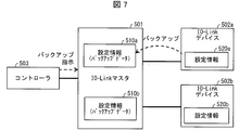
- FIG. 7 is a diagram illustrating a conventional technique, and is a diagram illustrating an overview of backup of setting information of an IO-Link device in an IO-Link system.
- the illustrated IO-Link system includes an IO-Link master 501 (corresponding to the aforementioned slave device), IO-Link devices 502a and 502b, and a controller 503 (corresponding to the aforementioned master device).
- IO-Link master 501 acquires the setting information 520a from the IO-Link device 502a and stores it as setting information 510a (backup data). The same applies to the IO-Link device 502b.
- a backup instruction addressed to the IO-Link device 502b is transmitted from the controller 503 to the IO-Link master 501, and the IO-Link master 501 acquires the setting information 520b from the IO-Link device 502b, and the setting information 510b (backup data)
- the IO-Link master 501 acquires the setting information 520b from the IO-Link device 502b, and the setting information 510b (backup data)
- a backup instruction to the IO-Link device is essential, and the processing when there are many IO-Link devices to be backed up becomes complicated. There was a problem. For example, when eight IO-Link devices are connected to one IO-Link master and all these backups are performed, the controller 503 has to perform the backup instruction eight times.
- Such a problem is not limited to the IO-Link system, and is a problem that commonly occurs in FA systems that can back up device setting information to a relay device such as a slave device.
- the present invention has been made in view of the above-described problems, and an object thereof is to realize a relay device or the like that can easily back up or restore setting information of a plurality of devices.
- a relay device relays data between a control device and a plurality of devices that are controlled by the control device and operate according to setting information
- An apparatus that receives a backup execution instruction for acquiring the setting information from the device and storing the setting information in a storage unit, or a restore execution instruction for transmitting the setting information stored in the storage unit to the device for storage A reception unit; and a setting information processing unit that executes backup of the plurality of devices or restores the plurality of devices according to one instruction received by the reception unit.
- a relay apparatus control method transmits data between a control apparatus and a plurality of devices that are controlled by the control apparatus and operate according to setting information.
- a method for controlling a relay device that relays, and that transmits the setting information acquired from the device and stores it in a storage unit or transmits the setting information stored in the storage unit to the device for storage A reception step for receiving a restore execution instruction, and a setting information processing step for executing backup of the plurality of devices or performing restoration of the plurality of devices in accordance with the one instruction received in the reception step; ,including.
- FIG. 1 It is a block diagram which shows an example of a principal part structure of the IO-Link master which concerns on Embodiment 1 of this invention. It is a figure which shows the outline
- Embodiment 3 of this invention is a figure which shows the example of the IO-Link system which disconnected the communication function with the high-order network in an IO-Link master as a communication coupler. It is a figure which shows a prior art and is a figure which shows the outline
- Embodiment 1 A first embodiment of the present invention will be described with reference to FIGS.
- FIG. 2 is a diagram showing an overview of the IO-Link system 9.
- the IO-Link system 9 is an FA system.
- the IO-Link system 9 includes an IO-Link master (relay device) 1, an IO-Link device 2a, an IO-Link device 2b, and a controller (control). Apparatus) 3, a support tool 4, and an HMI 5.
- IO-Link devices 2a and 2b these are expressed as IO-Link devices 2.
- the IO-Link master 1 is a relay device that relays data between the host network including the controller 3 and the IO-Link device 2, and operates as a slave device of the controller 3 in the IO-Link system 9.
- two IO-Link devices 2 are connected to the IO-Link master 1, but three or more IO-Link devices 2 can be connected.
- the IO-Link master 1 can communicate with the IO-Link device 2 bidirectionally.
- the IO-Link device 2 is a device that is connected to the IO-Link master 1 and is controlled by the controller 3.
- an output device and an input device can be applied.
- the input device include various sensors such as a photoelectric sensor and a proximity sensor.
- the output device include an actuator and a motor.
- a conversion device such as an inverter can also be used as the IO-Link device 2.
- the controller 3 is a control device that performs overall control of the IO-Link system 9 and is also called PLC (Programmable Logic Controller).
- the controller 3 operates as a master device of the IO-Link master 1 in the IO-Link system 9.
- the support tool 4 is a device used by connecting to the IO-Link system 9 for various settings in the IO-Link system 9 such as operation settings of the IO-Link device 2.
- the support tool 4 can be connected to the IO-Link system 9 via the controller 3.
- an information processing device such as a personal computer can be used, and a portable information processing device such as a notebook personal computer can also be used.
- the HMI 5 is a touch-panel display input device, and the user of the IO-Link system 9 may operate the controller 3 via the HMI 5 or check the operation state of the IO-Link system 9 via the HMI 5. it can.
- the IO-Link master 1 sets a plurality of IO-Link devices 2 in response to receiving one backup instruction from the controller 3 as shown in the figure. Back up the information 20 in a batch. More specifically, the IO-Link master 1 acquires the setting information 20a stored in the IO-Link device 2a from the IO-Link device 2a and stores it as backup data (setting information 111a). Further, the IO-Link master 1 acquires the setting information 20b stored in the IO-Link device 2b from the IO-Link device 2b and stores it as backup data (setting information 111b).
- setting information 111 when there is no need to distinguish between the setting information 111a and 111b, they are referred to as setting information 111. Similarly, when there is no need to distinguish between the setting information 20a and 20b, they are referred to as setting information 20.
- the setting information 20 is information indicating operation settings of the IO-Link device 2, and the IO-Link device 2 operates according to the setting information 20.
- a key lock setting that specifies whether or not to lock a setting by a hardware switch included in the photoelectric sensor, or ON when detecting light Outputs ON signal or OFF signal after satisfying LightON / DarkON setting that specifies whether to output signal or ON signal when light is not detected and ON signal or OFF signal output condition
- an ON (OFF) delay timer setting that defines a waiting time until the start is performed.
- the setting information 20 of the plurality of IO-Link devices 2 is backed up with one backup instruction, so that the setting information 20 of the plurality of IO-Link devices 2 can be easily backed up. it can.
- IO-Link is standardized under the name of “Single-drop digital communication interface for small sensors and actuators” (SDCI) in IEC 61131-9, and a master (the controller 3 corresponds to this) as a control device, A standardized technique for communication between devices such as sensors and actuators.
- SDCI single-drop digital communication interface for small sensors and actuators
- IO-Link is a new point-to-point serial communication protocol used for communication between masters and devices.
- An example of the device is a photoelectric sensor and a proximity switch.
- IO-Link is different from the conventional protocol that can only send on / off signals (1 bit) from the device to the master, and it can receive and send 32 bytes (256 bits) of data (bidirectional communication). It is a possible communication protocol.
- IO-Link By connecting the master and the device with IO-Link, a signal from a device that has conventionally received only binary data such as on / off information can be acquired as 32-byte numerical data. Therefore, for example, in the case of a photoelectric sensor, it becomes possible to acquire information such as the amount of received light, detection margin, internal temperature, etc., which is useful for investigating the cause of defects, as well as diagnosing product life and responding to deterioration over time.
- the threshold value can be changed.
- IO-Link By using IO-Link, for example, device settings and maintenance can be automated. Also, by using IO-Link, master programming can be greatly simplified, and the cost of wiring cables can be reduced.
- An IO-Link system consists of an IO-Link device (generally a sensor, actuator, or combination thereof, such as IO-Link device 2 above), a standard 3-wire sensor / actuator cable, and IO-Link And a master (the IO-Link master 1 corresponds to this).
- the IO-Link master has one or more ports (device communication port 12 described later corresponds to this), and one IO-Link device can be connected to each port.
- the IO-Link master performs point-to-point communication with the IO-Link device.
- the IO-Link master is not only binary data (1-bit data) such as conventional on / off information, but also device identification information, device communication properties, device parameters, and process / diagnostic data information, etc.
- Information other than binarized data (data larger than 1 bit) such as on / off information can be transmitted to and received from the IO-Link device.
- ⁇ IO-Link devices can send and receive data larger than 1 bit with the IO-Link master. That is, the IO-Link device is a device that conforms to IO-Link. In addition, devices such as sensors and actuators that are not IO-Link devices (not transmitting / receiving data larger than 1 bit) can be incorporated into the IO-Link system.
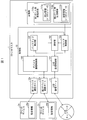
- FIG. 1 is a block diagram illustrating an example of a main configuration of the IO-Link master 1.
- the IO-Link master 1 includes a control unit 10 that controls each unit of the IO-Link master 1 and a storage unit 11 that stores various data used by the IO-Link master 1.
- the IO-Link master 1 includes a first device communication port 12a and a second device communication port 12b as communication ports for communicating with the IO-Link device 2.
- the IO-Link master 1 is provided with a host communication port 13 for communicating with a host network including the controller 3 described above. Note that when there is no need to distinguish between the first device communication port 12a and the second device communication port 12b, they are referred to as the device communication port 12.
- the number of device communication ports 12 may be three or more.
- the control unit 10 includes a device communication control unit 100, a higher-level communication control unit (reception unit) 101, a backup control unit (setting information processing unit) 102, a notification unit 103, and a restoration control unit (setting information processing unit) 104. It is included.
- the storage unit 11 includes a first port storage area 110a and a second port storage area 110b, and setting information 111a and 111b are stored in these storage areas, respectively. When there is no need to distinguish between the first port storage area 110a and the second port storage area 110b, they are referred to as the port storage area 110.
- the device communication control unit 100 controls communication with the IO-Link device 2.
- the upper communication control unit 101 controls communication with devices such as the controller 3 included in the upper network.
- the device communication control unit 100 accepts a backup instruction or a restore instruction from the upper network.
- Communication with the host network can be performed by, for example, EtherCAT (Ethernet Control Automation Technology: registered trademark).
- the backup control unit 102 controls backup of the setting information 20 stored in the IO-Link device 2. Specifically, the backup control unit 102 acquires the setting information 20 from the IO-Link device 2 and stores it as backup data (setting information 20) in the port storage area 110 corresponding to the IO-Link device 2. . The backup control unit 102 also performs a process of overwriting and updating the backup data with the setting information 20 acquired from the IO-Link device 2 that has already stored the backup data.
- the notification unit 103 When the backup processing by the backup control unit 102 is completed, the notification unit 103 notifies the upper network device to that effect. In addition, when there is an IO-Link device 2 for which backup or restoration has not ended normally, the notification unit 103 notifies the higher-level network device to that effect. Thereby, it is possible to make the user recognize the presence of the IO-Link device 2 whose backup or restoration has not been completed normally. Examples of higher-level network devices include the controller 3, the support tool 4, and the HMI 5.
- the restore control unit 104 sends the setting information 111 stored as backup data in the storage unit 11 to the IO-Link device 2 and updates the setting information 20 stored in the IO-Link device 2 Execute.
- the port storage area 110 is a storage area provided for each device communication port 12, and data related to each device communication port 12 is stored in the port storage area 110. Specifically, backup data (setting information) of the IO-Link device 2a connected to the first device communication port 12a is stored in the first port storage area 110a as data related to the first device communication port 12a. 111a) is stored. Similarly, backup data (setting information 111b) of the IO-Link device 2b connected to the second device communication port 12b is stored in the second port storage area 110b as data related to the second device communication port 12b. Is memorized.
- the backup timing is not particularly limited.
- the backup may be performed when the IO-Link system 9 is started up.
- each device constituting the IO-Link system 9 is connected by communication using a predetermined communication cable, and then initial setting of each device is performed.
- the initial setting can be performed via the support tool 4, and at the end of the initial setting, the setting information 20 is stored in the IO-Link device 2.
- the initial setting makes the IO-Link system 9 ready for operation. After the initial setting is completed, a trial run is performed to check whether the entire IO-Link system 9 is in the desired operating state. If there is a problem as a result of this confirmation, adjustments such as correction of the setting information 20 are performed, and the setting information 20 is backed up when the apparatus is operating without any problems.
- the setting information 20 can be corrected via the support tool 4, and the IO-Link device 2 having an input unit can also be corrected via the input unit.
- the backup is executed by the IO-Link master 1 by transmitting a backup instruction from the controller 3, the support tool 4 or the HMI 5 to the IO-Link master 1. Then, the start-up is completed by the end of the backup, and the IO-Link system 9 becomes operable.
- FIG. 3 is a diagram illustrating an example in which a backup instruction is transmitted from the host network to the IO-Link master 1.
- the backup instruction can be transmitted from the support tool 4 to the IO-Link master 1 via the controller 3 as shown in FIG. Further, as shown in FIG. 5B, a backup instruction can be transmitted from the HMI 5 to the IO-Link master 1 via the controller 3. Control that is irregularly performed in IO-Link, such as this backup instruction, is performed by transmitting a command in a predetermined format called a message.
- the message may be generated by the controller 3 or by the HMI 5 or the support tool 4.
- a backup instruction message may be generated by the support tool 4, and this may be relayed by the controller 3 and transmitted to the IO-Link master 1. Further, the controller 3 may generate a backup instruction message in response to a backup instruction from the support tool 4 to the controller 3 and transmit it to the IO-Link master 1. The same applies to the example of FIG.
- the source of the backup instruction is not limited to the above examples.
- a backup instruction can be directly transmitted to the IO-Link master 1 by the wireless communication function.
- a hardware key button, etc.
- a similar hardware key may be provided in the IO-Link device 2. In this case, the IO-Link device 2 notifies the IO-Link master 1 that the hardware key has been operated.
- the IO-Link master 1 may back up a plurality of IO-Link devices 2 including the IO-Link device 2 to be operated.
- the backup can be performed without using the support tool 4 or the like, so that the staff from the IO-Link system 9 installation site can smoothly perform the processing from the startup of the IO-Link system 9 to the backup. It becomes possible to perform simply.
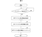
- FIG. 4 is a flowchart showing an example of backup processing (relay device control method) by the IO-Link master 1.
- the backup control unit 102 is waiting for a backup instruction (S1, reception step).
- a backup instruction is detected (YES in S1)
- the backup control unit 102 instructs the IO-Link device 2 connected to each device communication port 12 to transmit the setting information 20 (S2). ).
- each IO-Link device 2 transmits the setting information 20 to the IO-Link master 1 as a response to the instruction, the backup control unit 102 receives the setting information 20 (S3).
- the backup control unit 102 sets the received setting information 20 as setting information 111 in the port storage area 110 corresponding to the device communication port 12 to which the IO-Link device 2 that is the transmission source of the setting information 20 is connected.
- the notification unit 103 notifies that to the upper network device such as the backup instruction transmission source (support tool 4 or HMI 5) received by the controller 3 or S1. Then, the process ends.
- the backup for a plurality of IO-Link devices 2 may be performed concurrently or sequentially. Further, the backup may fail due to a communication error or the IO-Link device 2 not connected to the device communication port 12.
- the notification unit 103 may notify information (device identification information, device communication port 12 identification information, etc.) indicating the IO-Link device 2 that has failed to be backed up to a device in the upper network. If the reason for the backup failure is known, the reason may also be notified. As a result, it is possible to allow the user to recognize the existence of the IO-Link device 2 that failed to be backed up and the reason thereof on the HMI 5, for example.
- FIG. 5 is a diagram illustrating an example of the IO-Link master 1 that restores a plurality of IO-Link devices 2 in response to one restore instruction.
- the same reference number is attached
- the IO-Link master 1 transmits setting information 111 to each of the plurality of IO-Link devices 2 in response to receiving one restore instruction from the controller 3. Restore the setting information 20 of the IO-Link device 2. More specifically, the restore control unit 104 of the IO-Link master 1 transmits the setting information 111a to the IO-Link device 2a and stores it as the setting information 20a. Similarly, the restore control unit 104 transmits the setting information 111b to the IO-Link device 2b and stores it as the setting information 20b. If the setting information 20 is already stored, it is overwritten with the transmitted setting information 111.
- a plurality of IO-Link devices 2 are restored by one restore instruction, so that a plurality of IO-Link devices 2 can be easily restored. .
- a restore instruction may be input to the IO-Link master 1 from the support tool 4 or HMI 5 via the controller 3, or to the IO-Link master 1 without passing through other devices. It is also possible to send a restore instruction directly.
- the IO-Link master 1 has at least one of a function for restoring a plurality of IO-Link devices 2 with one restore instruction and a function for backing up a plurality of IO-Link devices 2 with one backup instruction. It only has to have.
- FIG. 6 is a diagram illustrating an example of the IO-Link system 92 in which the communication function with the host network in the IO-Link master is separated as a communication coupler.
- the illustrated IO-Link system 92 is a system having the same functions as the IO-Link system 9 described above, but instead of the IO-Link master 1 of the IO-Link system 9, a communication coupler 200 and an IO-Link master are provided. The difference is that 201 is provided.
- the communication coupler 200 is a relay device that relays communication between the host network and the IO-Link master 201.
- the communication coupler 200 includes a communication port corresponding to the host communication port 13 (see FIG. 1) of the IO-Link master 1 and a communication port for communicating with the IO-Link master 201.
- the communication coupler 200 includes a communication control unit corresponding to the upper communication control unit 101 (see FIG. 1) of the IO-Link master 1, and the communication control unit and the IO-Link master are included in the upper network. The communication is relayed to and from 201.
- the IO-Link master 201 has the same configuration as the IO-Link master 1 except that it includes a communication port for communicating with the communication coupler 200 instead of the host communication port 13 (see FIG. 1). Yes.
- a backup instruction is transmitted from the controller 3 in the same manner as the IO-Link system 9 described above, but this backup instruction is received by the IO-Link master 201 via the communication coupler 200. Note that the backup process after receiving the backup instruction is the same as that of the IO-Link master 1, and therefore the description thereof will not be repeated here.
- a backup instruction can be transmitted from the support tool 4 to the communication coupler 200 via the interface.
- the backup instruction is transferred from the communication coupler 200 to the IO-Link master 201.
- the IO-Link master 201 has an interface for connecting the support tool 4
- a backup instruction can be directly transmitted from the support tool 4 to the IO-Link master 201 via the interface.
- the IO-Link master 201 of the IO-Link system 92 restores a plurality of IO-Link devices 2 in response to receiving one restore instruction in the same manner as the IO-Link master 2 of the second embodiment. Can be done.
- the FA system using IO-Link has been described as an example.
- backup of a device is performed by a slave device, and bidirectional communication is performed between the device and the slave device. It can be applied to any FA system that can handle the above. For example, it can be applied to an FA system using CC-Link or the like.
- the slave device Backup and restoration may be performed collectively for these multiple devices.
- cyclic communication is performed at a predetermined cycle.
- the controller 3 transmits cyclic data to the IO-Link master 1, and the cyclic data is transmitted from the IO-Link master 1 to each IO-Link device 2.
- the cyclic data is returned from each IO-Link device 2 to the controller 3 via the IO-Link master 1.
- the cyclic data is shared among the devices constituting the IO-Link system 9.
- the IO-Link masters 1 and 201 may instruct backup and restoration by cyclic communication as described above.
- the IO-Link master 1 can perform a batch backup or a batch restore.
- a flag corresponding to the backup instruction and a flag corresponding to the restore instruction may be included in the cyclic data.
- the controller 3 switches the flag ON / OFF, whereby backup or restoration can be performed at the timing when the flag is turned ON.
- the backup instruction and the restore instruction may include designation information for designating a control target such as identification information of the target device communication port 12 and identification information of the IO-Link device 2.
- the backup control unit 102 backs up the device specified by the specified information
- the restore control unit 104 restores the device specified by the specified information.
- a plurality of backup and restoration targets can be specified, whereby backup and restoration of a plurality of IO-Link devices 2 can be performed easily and quickly.
- the backup control unit 102 may determine whether or not backup is necessary for each IO-Link device 2 to be backed up, and may only consider the IO-Link device 2 determined to be backed up. For example, backup valid / invalid settings for each device communication port 12 are stored in advance, and only the IO-Link device 2 connected to the device communication port 12 for which this setting is valid may be the backup target. Good.
- the IO-Link master 1 can be configured to determine whether or not the setting information 20 stored in the IO-Link device 2 matches the setting information 111 stored as backup data. May be provided. Then, when the backup unit is received within a predetermined time after the determination unit performs the determination, the IO-Link device 2 whose collation result does not match is targeted for backup and the IO-Link device whose collation result is the same. 2 may be excluded from the backup target.
- the above examples can be similarly applied to restoration.
- the control block of the IO-Link master 1 (particularly, each unit included in the control unit 10) may be realized by a logic circuit (hardware) formed in an integrated circuit (IC chip) or the like, or a CPU (Central Processing Unit) ) May be implemented by software.
- a logic circuit hardware
- IC chip integrated circuit
- CPU Central Processing Unit
- the IO-Link master 1 includes a CPU that executes instructions of a program that is software that implements each function, and a ROM (Read Only Memory) in which the program and various data are recorded so as to be readable by the computer (or CPU) ) Or a storage device (these are referred to as “recording media”), a RAM (Random Access Memory) that expands the program, and the like.
- the objective of this invention is achieved when a computer (or CPU) reads the said program from the said recording medium and runs it.
- a “non-temporary tangible medium” such as a tape, a disk, a card, a semiconductor memory, a programmable logic circuit, or the like can be used.
- the program may be supplied to the computer via an arbitrary transmission medium (such as a communication network or a broadcast wave) that can transmit the program.
- the present invention can also be realized in the form of a data signal embedded in a carrier wave in which the program is embodied by electronic transmission.
- the control block of apparatuses, such as IO-Link master 201 and the communication coupler 200, can also be implement
- a relay device is a relay device that relays data between a control device and a plurality of devices that are controlled by the control device and operate according to setting information.
- a receiving unit that receives a backup execution instruction for acquiring setting information and storing the setting information in a storage unit, or a restore execution instruction for transmitting the setting information stored in the storage unit to the device for storage, and the reception unit
- a setting information processing unit that executes backup of the plurality of devices or restores the plurality of devices in response to a single instruction.
- the setting information processing unit may execute backup of the device specified by the specification information when the specification information specifying the device is included in the one instruction received by the reception unit, or The device specified by the specification information may be restored.
- setting information of a specified device among a plurality of devices can be backed up, or setting information can be restored to the specified device.
- the relay apparatus may include a notification unit that notifies a user of a device in which backup or restoration has not been normally completed among the plurality of devices that the setting information processing unit has been subjected to backup or restoration. Good.
- the device may be an IO-Link device. Since many IO-Link devices are often connected to one relay device and used, it is possible to easily back up and restore the setting information of such many IO-Link devices. The benefits are particularly great.
- the relay apparatus control method is a relay apparatus control method that relays data between a control apparatus and a plurality of devices that are controlled by the control apparatus and operate according to setting information. And accepting a backup execution instruction for acquiring the setting information from the device and storing it in a storage unit, or a restore execution instruction for transmitting the setting information stored in the storage unit to the device for storage And a setting information processing step for executing backup of the plurality of devices or restoring of the plurality of devices according to one instruction received in the receiving step. According to the control method, the same operation and effect as the above-described relay device are achieved.
- control program for causing a computer to function as the relay device by causing the computer to execute the above steps and a computer-readable recording medium on which the control program is recorded are also included in the scope of the present invention.
- IO-Link master (relay device) 11 Storage Unit 101 Host Communication Control Unit (Reception Unit) 102 Backup control unit (setting information processing unit) 103 Notification unit 104 Restore control unit (setting information processing unit) 111 Setting information (backup data) 2 IO-Link device (device) 20 Setting information 3 Controller (control device) 201 IO-Link master (relay device)
Landscapes
- Engineering & Computer Science (AREA)
- Physics & Mathematics (AREA)
- General Physics & Mathematics (AREA)
- Automation & Control Theory (AREA)
- General Engineering & Computer Science (AREA)
- Manufacturing & Machinery (AREA)
- Quality & Reliability (AREA)
- Programmable Controllers (AREA)
- Information Retrieval, Db Structures And Fs Structures Therefor (AREA)
Abstract
バックアップやリストアの対象となるデバイスの数が増えるほど送信すべき命令の数が増加して処理が煩雑になる。IO-Linkマスタ(1)は、IO-Linkデバイス(2)から設定情報(20)を取得して記憶部(11)に記憶するバックアップの実行指示を受け付ける上位通信制御部(101)と、受け付けた一の指示に応じて、複数のIO-Linkデバイス(2)のバックアップを実行するバックアップ制御部(102)とを備えている。
Description
本発明はFA(Factory Automation)システムにおいて制御装置とデバイスとの間でデータを中継する中継装置に関し、より詳細にはデバイスの設定情報をバックアップする機能を有する中継装置等に関する。
一般的なFAシステムは、マスタ装置(制御装置)とスレーブ装置(中継装置)とセンサ等のデバイスとを含み、マスタ装置がスレーブ装置を介してデバイスの動作制御やデバイスの出力データの受信を行う。このようなFAシステムの改良が従来から進められている。例えば、下記の特許文献1には、制御機器(前述のスレーブ装置に相当)のパラメータ設定を、PLC(Programmable Logic Controller、前述のマスタ装置に相当)にバックアップする際のデータ通信量を削減する技術が開示されている。
また、FAシステムで利用されるIO-Link(登録商標)プロトコルでは、IO-Linkデバイスの設定情報をIO-Linkマスタにバックアップすることが可能になっている。これについて、図7に基づいて説明する。図7は、従来技術を示す図であり、IO-LinkシステムにおけるIO-Linkデバイスの設定情報のバックアップの概要を示す図である。
図示のIO-Linkシステムには、IO-Linkマスタ501(前述のスレーブ装置に相当)、IO-Linkデバイス502a、502b、およびコントローラ503(前述のマスタ装置に相当)が含まれている。
このIO-Linkシステムにおいて、IO-Linkデバイス502aの設定情報520aをバックアップする場合、図示のようにコントローラ503からIO-Linkマスタ501にIO-Linkデバイス502a宛のバックアップ指示を送信する。これにより、IO-Linkマスタ501がIO-Linkデバイス502aから設定情報520aを取得し、設定情報510a(バックアップデータ)として記憶する。IO-Linkデバイス502bについても同様である。すなわち、コントローラ503からIO-Linkマスタ501にIO-Linkデバイス502b宛のバックアップ指示を送信し、IO-Linkマスタ501がIO-Linkデバイス502bから設定情報520bを取得し、設定情報510b(バックアップデータ)として記憶する。
前述の従来技術には、IO-Linkデバイスのバックアップを行うためには、そのIO-Linkデバイスへのバックアップ指示が必須であり、バックアップしたいIO-Linkデバイスが多数存在する場合の処理が煩雑になるという問題があった。例えば、1つのIO-Linkマスタに8台のIO-Linkデバイスが接続されており、これら全てのバックアップを行う場合には、コントローラ503は8回のバックアップ指示を行う必要があった。
また、IO-Linkシステムでは、バックアップデータをIO-Linkデバイスに送信して記憶させるリストアを行うこともできるが、リストアについても前記と同じ問題がある。つまり、複数のIO-Linkデバイスにリストアを行う場合には、IO-Linkデバイスの数だけリストア指示を行う必要があり、対象となるIO-Linkデバイスの数が増えるほど処理が煩雑になる。
なお、このような問題は、IO-Linkシステムに限られず、スレーブ装置等の中継装置にデバイスの設定情報をバックアップすることができるFAシステムに共通して生じる問題である。
本発明は、前記の問題点に鑑みてなされたものであり、その目的は、複数のデバイスの設定情報を簡単にバックアップまたはリストアすることができる中継装置等を実現することにある。
上記の課題を解決するために、本発明の一態様に係る中継装置は、制御装置と、前記制御装置の制御対象であり、設定情報に従って動作する複数のデバイスとの間でデータを中継する中継装置であって、前記デバイスから前記設定情報を取得して記憶部に記憶するバックアップの実行指示、または前記記憶部に記憶された設定情報を前記デバイスに送信して記憶させるリストアの実行指示を受け付ける受付部と、前記受付部が受け付けた一の指示に応じて、前記複数のデバイスのバックアップを実行するか、または前記複数のデバイスのリストアを実行する設定情報処理部と、を備えている。
本発明の一態様に係る中継装置の制御方法は、上記の課題を解決するために、制御装置と、前記制御装置の制御対象であり、設定情報に従って動作する複数のデバイスとの間でデータを中継する中継装置の制御方法であって、前記デバイスから前記設定情報を取得して記憶部に記憶するバックアップの実行指示、または前記記憶部に記憶された設定情報を前記デバイスに送信して記憶させるリストアの実行指示を受け付ける受付ステップと、前記受付ステップにて受け付けた一の指示に応じて、前記複数のデバイスのバックアップを実行するか、または前記複数のデバイスのリストアを実行する設定情報処理ステップと、を含む。
本発明の一態様によれば、複数のデバイスの設定情報を簡単にバックアップまたはリストアすることができるという効果を奏する。
〔実施形態1〕
本発明の実施形態1について図1~図4に基づいて説明する。
本発明の実施形態1について図1~図4に基づいて説明する。
〔システム概要〕
まず、本実施形態のIO-Linkシステムの概要を図2に基づいて説明する。図2は、IO-Linkシステム9の概要を示す図である。IO-Linkシステム9は、FAシステムであり、図示のように、IO-Linkシステム9には、IO-Linkマスタ(中継装置)1、IO-Linkデバイス2a、IO-Linkデバイス2b、コントローラ(制御装置)3、サポートツール4、およびHMI5が含まれている。なお、IO-Linkデバイス2aと2bを区別する必要のないときには、これらをIO-Linkデバイス2と表記する。
まず、本実施形態のIO-Linkシステムの概要を図2に基づいて説明する。図2は、IO-Linkシステム9の概要を示す図である。IO-Linkシステム9は、FAシステムであり、図示のように、IO-Linkシステム9には、IO-Linkマスタ(中継装置)1、IO-Linkデバイス2a、IO-Linkデバイス2b、コントローラ(制御装置)3、サポートツール4、およびHMI5が含まれている。なお、IO-Linkデバイス2aと2bを区別する必要のないときには、これらをIO-Linkデバイス2と表記する。
IO-Linkマスタ1は、コントローラ3等を含む上位ネットワークとIO-Linkデバイス2との間でデータを中継する中継装置であり、IO-Linkシステム9においてコントローラ3のスレーブ装置として動作する。図示の例では、IO-Linkマスタ1には2つのIO-Linkデバイス2が接続されているが、3つ以上のIO-Linkデバイス2を接続することもできる。また、IO-Linkマスタ1はIO-Linkデバイス2と双方向に通信することができる。
IO-Linkデバイス2は、IO-Linkマスタ1と通信接続されて、コントローラ3の制御対象となる装置である。IO-Linkデバイス2としては、出力系のデバイスおよび入力系のデバイスを適用できる。入力系のデバイスとしては、例えば光電センサや近接センサ等の各種センサが挙げられ、出力系のデバイスとしては例えばアクチュエータやモータ等が挙げられる。また、インバータのような変換装置等もIO-Linkデバイス2とすることができる。
コントローラ3は、IO-Linkシステム9の全体を統括して制御する制御装置であり、PLC(Programmable Logic Controller)とも呼ばれる。コントローラ3は、IO-Linkシステム9においてIO-Linkマスタ1のマスタ装置として動作する。
サポートツール4は、IO-Linkデバイス2の動作設定等のIO-Linkシステム9における各種設定のために、IO-Linkシステム9に接続して使用される装置である。サポートツール4は、コントローラ3経由でIO-Linkシステム9に接続することができる。サポートツール4としては、パソコンのような情報処理装置を用いることができ、ノート型パソコンのような携帯型の情報処理装置を用いることもできる。
HMI5は、タッチパネル式の表示入力装置であり、IO-Linkシステム9のユーザは、HMI5を介してコントローラ3を操作したり、HMI5にてIO-Linkシステム9の動作状態を確認したりすることができる。
以上のような構成を備えるIO-Linkシステム9において、IO-Linkマスタ1は、図示のように、コントローラ3から一のバックアップ指示を受信したことに応じて、複数のIO-Linkデバイス2の設定情報20を一括でバックアップする。より詳細には、IO-Linkマスタ1は、IO-Linkデバイス2aから、当該IO-Linkデバイス2aが記憶している設定情報20aを取得して、バックアップデータとして記憶する(設定情報111a)。さらに、IO-Linkマスタ1は、IO-Linkデバイス2bから、当該IO-Linkデバイス2bが記憶している設定情報20bを取得して、バックアップデータとして記憶する(設定情報111b)。
なお、設定情報111aと111bを区別する必要のないときには、これらを設定情報111と表記する。同様に、設定情報20aと20bを区別する必要のないときには、これらを設定情報20と表記する。また、設定情報20は、IO-Linkデバイス2の動作設定を示す情報であり、IO-Linkデバイス2は設定情報20に従って動作する。例えば、IO-Linkデバイス2が光電センサである場合の設定情報20の例としては、光電センサの備えるハードウェアスイッチによる設定をロックするか否かを規定したキーロック設定や、光の検出時にON信号を出力するか、光が非検出となったときにON信号を出力するかを規定したLightON/DarkON設定、およびON信号またはOFF信号の出力条件を満たした後、ON信号またはOFF信号を出力するまでの待機時間を規定したON(OFF)ディレータイマ設定等が挙げられる。
このように、IO-Linkシステム9では、一のバックアップ指示で複数のIO-Linkデバイス2の設定情報20をバックアップするので、複数のIO-Linkデバイス2の設定情報20を簡単にバックアップすることができる。
〔IO-Linkについて〕
IO-Linkについて、以下に補足説明する。IO-Linkは、IEC61131-9において「Single-drop digital communication interface for small sensors and actuators」(SDCI)という名称で規格化されており、制御装置であるマスタ(前記コントローラ3がこれに該当)と、センサおよびアクチュエータ等のデバイスとの間の通信のための標準化技術である。IO-Linkは、マスタとデバイスとの通信に使用する新しいポイント・ツー・ポイントシリアル通信プロトコルである。なお、前記デバイスの一例として、光電センサと近接スイッチとを挙げることができる。
IO-Linkについて、以下に補足説明する。IO-Linkは、IEC61131-9において「Single-drop digital communication interface for small sensors and actuators」(SDCI)という名称で規格化されており、制御装置であるマスタ(前記コントローラ3がこれに該当)と、センサおよびアクチュエータ等のデバイスとの間の通信のための標準化技術である。IO-Linkは、マスタとデバイスとの通信に使用する新しいポイント・ツー・ポイントシリアル通信プロトコルである。なお、前記デバイスの一例として、光電センサと近接スイッチとを挙げることができる。
IO-Linkは、デバイスからマスタへのオン/オフ信号(1ビット)の発信のみが可能であった従来のプロトコルとは異なり、32バイト(256ビット)のデータの受発信(双方向通信)が可能な通信プロトコルである。マスタとデバイスとの間をIO-Linkでつなぐことによって、従来、オン/オフ情報などの2値化データしか受信できなかったデバイスからの信号について、32バイトの数値データとして取得できるようになる。したがって、例えば、光電センサの場合、受光量、検出余裕度、内部温度などの情報を取得することができるようになり、不具合原因の究明に役立つほか、製品寿命の診断、経年劣化に応じたしきい値の変更などが可能になる。
IO-Linkを利用することにより、例えば、デバイスの設定およびメンテナンス等を自動化することができる。また、IO-Linkを利用することにより、マスタのプログラミングが大幅に簡易化でき、さらに、配線ケーブルのコスト削減等を実現することができる。
続いて、以上説明したIO-Linkを利用したIO-Linkシステム(前記IO-Linkシステム9がこれに該当)について説明する。IO-Linkシステムは、IO-Linkデバイス(一般に、センサ、アクチュエータ、またはその組み合わせであり、前記IO-Linkデバイス2がこれに該当)と、標準の3線式センサ/アクチュエータケーブルと、IO-Linkマスタ(上記IO-Linkマスタ1がこれに該当)と、によって構成される。
IO-Linkマスタは、1つまたは複数のポート(後述のデバイス通信ポート12がこれに該当)を備え、各ポートには1台のIO-Linkデバイスが接続可能である。IO-Linkマスタは、IO-Linkデバイスとポイントツーポイント通信を行う。IO-Linkマスタは、従来のオン/オフ情報などの2値化データ(1ビットのデータ)だけでなく、デバイスの識別情報、デバイスの通信プロパティ、デバイスパラメータ、および、プロセス・診断データの情報などの、オン/オフ情報などの2値化データ以外の情報(1ビットよりも大きなデータ)を、IO-Linkデバイスとの間で送受信することができる。
IO-Linkデバイスは、IO-Linkマスタとの間で、1ビットよりも大きなデータを送受信することができる。つまり、IO-Linkデバイスは、IO-Linkに適合したデバイスである。なお、IO-Linkシステムには、IO-Linkデバイスではない(1ビットよりも大きなデータを送受信しない)センサやアクチュエータ等のデバイスを組み込むこともできる。
〔IO-Linkマスタの要部構成〕
次に、IO-Linkマスタ1の要部構成を図1に基づいて説明する。図1は、IO-Linkマスタ1の要部構成の一例を示すブロック図である。図示のように、IO-Linkマスタ1は、IO-Linkマスタ1の各部を統括して制御する制御部10、IO-Linkマスタ1にて使用する各種データを記憶する記憶部11を備えている。また、IO-Linkマスタ1は、IO-Linkデバイス2と通信するための通信ポートとして、第1デバイス通信ポート12aおよび第2デバイス通信ポート12bを備えている。さらに、IO-Linkマスタ1は、上述のコントローラ3を含む上位ネットワークと通信するための上位通信ポート13を備えている。なお、第1デバイス通信ポート12aと第2デバイス通信ポート12bを区別する必要のないときには、これらをデバイス通信ポート12と表記する。また、デバイス通信ポート12の数は3以上であってもよい。
次に、IO-Linkマスタ1の要部構成を図1に基づいて説明する。図1は、IO-Linkマスタ1の要部構成の一例を示すブロック図である。図示のように、IO-Linkマスタ1は、IO-Linkマスタ1の各部を統括して制御する制御部10、IO-Linkマスタ1にて使用する各種データを記憶する記憶部11を備えている。また、IO-Linkマスタ1は、IO-Linkデバイス2と通信するための通信ポートとして、第1デバイス通信ポート12aおよび第2デバイス通信ポート12bを備えている。さらに、IO-Linkマスタ1は、上述のコントローラ3を含む上位ネットワークと通信するための上位通信ポート13を備えている。なお、第1デバイス通信ポート12aと第2デバイス通信ポート12bを区別する必要のないときには、これらをデバイス通信ポート12と表記する。また、デバイス通信ポート12の数は3以上であってもよい。
そして、制御部10には、デバイス通信制御部100、上位通信制御部(受付部)101、バックアップ制御部(設定情報処理部)102、通知部103、およびリストア制御部(設定情報処理部)104が含まれている。また、記憶部11には、第1ポート用記憶領域110aと第2ポート用記憶領域110bが含まれており、これらの記憶領域にはそれぞれ設定情報111aと111bが記憶されている。なお、第1ポート用記憶領域110aと第2ポート用記憶領域110bを区別する必要のないときには、これらをポート用記憶領域110と表記する。
デバイス通信制御部100は、IO-Linkデバイス2との通信を制御する。また、上位通信制御部101は、上位ネットワークに含まれるコントローラ3等の装置との通信を制御する。例えば、デバイス通信制御部100は、上位ネットワークからのバックアップ指示やリストア指示を受け付ける。上位ネットワークとの通信は、例えばEtherCAT(EthernetControl Automation Technology:登録商標)等にて行うことができる。
バックアップ制御部102は、IO-Linkデバイス2が記憶している設定情報20のバックアップを制御する。具体的には、バックアップ制御部102は、IO-Linkデバイス2から設定情報20を取得して、該IO-Linkデバイス2に対応するポート用記憶領域110にバックアップデータ(設定情報20)として記憶する。また、バックアップ制御部102は、すでにバックアップデータを記憶済みのIO-Linkデバイス2から取得した設定情報20にて前記バックアップデータを上書きして更新する処理も行う。
通知部103は、バックアップ制御部102によるバックアップ処理が終了したときに、上位ネットワークの機器にその旨を通知する。また、通知部103は、バックアップまたはリストアが正常に終了しなかったIO-Linkデバイス2がある場合には、上位ネットワークの機器にその旨を通知する。これにより、バックアップまたはリストアが正常に終了しなかったIO-Linkデバイス2の存在をユーザに認識させることができる。なお、上位ネットワークの機器としては、例えばコントローラ3、サポートツール4、HMI5等が挙げられる。
リストア制御部104は、記憶部11にバックアップデータとして記憶されている設定情報111をIO-Linkデバイス2に送信して、該IO-Linkデバイス2が記憶している設定情報20を更新させるリストア処理を実行する。
ポート用記憶領域110は、各デバイス通信ポート12のそれぞれについて設けられた記憶領域であり、ポート用記憶領域110には各デバイス通信ポート12に関連するデータが記憶される。具体的には、第1ポート用記憶領域110aには、第1デバイス通信ポート12aに関連するデータとして、該第1デバイス通信ポート12aに接続されているIO-Linkデバイス2aのバックアップデータ(設定情報111a)が記憶される。同様に、第2ポート用記憶領域110bには、第2デバイス通信ポート12bに関連するデータとして、該第2デバイス通信ポート12bに接続されているIO-Linkデバイス2bのバックアップデータ(設定情報111b)が記憶される。
〔システムの立ち上げとバックアップ〕
バックアップのタイミングは特に限定されないが、例えばIO-Linkシステム9の立ち上げ時にバックアップを行ってもよい。IO-Linkシステム9の立ち上げ時には、まずIO-Linkシステム9を構成する各機器を所定の通信ケーブルで接続する等して通信接続した上で、各機器の初期設定を行う。初期設定は、サポートツール4を介して行うことができ、初期設定の終了時には、IO-Linkデバイス2には設定情報20が記憶された状態となる。
バックアップのタイミングは特に限定されないが、例えばIO-Linkシステム9の立ち上げ時にバックアップを行ってもよい。IO-Linkシステム9の立ち上げ時には、まずIO-Linkシステム9を構成する各機器を所定の通信ケーブルで接続する等して通信接続した上で、各機器の初期設定を行う。初期設定は、サポートツール4を介して行うことができ、初期設定の終了時には、IO-Linkデバイス2には設定情報20が記憶された状態となる。
初期設定を行うことにより、IO-Linkシステム9は運転可能な状態となるので、初期設定終了後に試運転を行って、IO-Linkシステム9の全体が所望の動作状態となるか確認する。この確認の結果、問題があれば、設定情報20の修正などの調整を行い、問題なく稼働する状態となった時点で設定情報20のバックアップを行う。なお、設定情報20の修正は、サポートツール4を介して行うこともできるし、入力部を備えたIO-Linkデバイス2については該入力部を介して行うこともできる。
バックアップは、コントローラ3、サポートツール4、またはHMI5から、IO-Linkマスタ1にバックアップ指示を送信することにより、IO-Linkマスタ1が実行する。そして、バックアップの終了により立ち上げは終了し、IO-Linkシステム9は稼働可能な状態となる。
〔バックアップの契機〕
IO-Linkマスタ1によるバックアップは、上位ネットワークからの指示によって実行させることができる。これについて図3に基づいて説明する。図3は、上位ネットワークからIO-Linkマスタ1にバックアップ指示を送信する例を示す図である。
IO-Linkマスタ1によるバックアップは、上位ネットワークからの指示によって実行させることができる。これについて図3に基づいて説明する。図3は、上位ネットワークからIO-Linkマスタ1にバックアップ指示を送信する例を示す図である。
同図の(a)に示すように、サポートツール4からコントローラ3を介してIO-Linkマスタ1にバックアップ指示を送信することができる。また、同図の(b)に示すように、HMI5からコントローラ3を介してIO-Linkマスタ1にバックアップ指示を送信することができる。このバックアップ指示等のようにIO-Linkにおいて不定期に行われる制御は、メッセージと呼ばれる所定の形式の命令を送信することによって行われる。なお、メッセージの生成はコントローラ3で行ってもよいし、HMI5やサポートツール4で行ってもよい。例えば、同図の(a)の例では、サポートツール4にてバックアップ指示のメッセージを生成して、これをコントローラ3が中継してIO-Linkマスタ1に送信してもよい。また、サポートツール4からコントローラ3へのバックアップ指示に応じてコントローラ3がバックアップ指示のメッセージを生成し、IO-Linkマスタ1に送信してもよい。同図の(b)の例においても同様である。
なお、バックアップ指示の出所は、上述の各例に限られない。例えば、IO-Linkマスタ1が無線通信機能を備えている場合には、該無線通信機能により直接IO-Linkマスタ1にバックアップ指示を送信することも可能である。また、例えばバックアップを行わせるためのハードウエアキー(ボタン等)をIO-Linkマスタ1に設け、このハードウエアキーが操作されたことを契機として、複数のIO-Linkデバイス2のバックアップを行ってもよい。さらに、同様のハードウエアキーをIO-Linkデバイス2に設けてもよい。この場合、ハードウエアキーが操作されたことをIO-Linkデバイス2がIO-Linkマスタ1に通知する。そして、この通知(バックアップ指示)を契機として、IO-Linkマスタ1が操作対象となったIO-Linkデバイス2を含む複数のIO-Linkデバイス2のバックアップを行ってもよい。これらの構成では、サポートツール4等を使用することなくバックアップを行うことができるので、IO-Linkシステム9の立ち上げからバックアップまでの処理を、IO-Linkシステム9の設置場所のスタッフがスムーズかつ簡易に行うことが可能になる。
〔処理の流れ〕
次に、IO-Linkマスタ1が実行する処理の流れを図4に基づいて説明する。図4は、IO-Linkマスタ1によるバックアップ処理(中継装置の制御方法)の一例を示すフローチャートである。
次に、IO-Linkマスタ1が実行する処理の流れを図4に基づいて説明する。図4は、IO-Linkマスタ1によるバックアップ処理(中継装置の制御方法)の一例を示すフローチャートである。
バックアップ制御部102は、バックアップ指示を待ち受けている(S1、受付ステップ)。ここで、バックアップ指示を検出した場合(S1でYES)、バックアップ制御部102は、各デバイス通信ポート12に接続されているIO-Linkデバイス2に対して、設定情報20の送信を指示する(S2)。
次に、前記指示に対する応答として各IO-Linkデバイス2がIO-Linkマスタ1に設定情報20を送信するので、バックアップ制御部102は、これらの設定情報20を受信する(S3)。
そして、バックアップ制御部102は、受信した設定情報20を、その設定情報20の送信元のIO-Linkデバイス2が接続されているデバイス通信ポート12に対応するポート用記憶領域110に設定情報111として記憶する(S4、設定情報処理ステップ)。また、全てのIO-Linkデバイス2のバックアップが終了すると、通知部103がその旨を、コントローラ3やS1で受け付けたバックアップ指示の送信元(サポートツール4やHMI5)等の上位ネットワークの機器に通知し、処理は終了する。
なお、複数のIO-Linkデバイス2についてのバックアップは、同時並行で行ってもよいし、順次行ってもよい。また、通信エラーや、デバイス通信ポート12にIO-Linkデバイス2が接続されていない等の理由により、バックアップが失敗することがあり得る。このような場合、通知部103は、バックアップが失敗したIO-Linkデバイス2を示す情報(デバイスの識別情報やデバイス通信ポート12の識別情報等)を上位ネットワークの機器に通知してもよい。また、バックアップ失敗の理由が判明している場合には、その理由についても併せて通知してもよい。これにより、バックアップが失敗したIO-Linkデバイス2が存在することや、その理由を、例えばHMI5に表示させることにより、ユーザに認識させることが可能になる。
〔実施形態2〕
本発明の実施形態2について図5に基づいて説明する。図5は、一のリストア指示に応じて複数のIO-Linkデバイス2のリストアを行うIO-Linkマスタ1の例を示す図である。なお、前記実施形態と同様の構成には同一の参照番号を付し、その説明を省略する。実施形態3以降についても同様である。
本発明の実施形態2について図5に基づいて説明する。図5は、一のリストア指示に応じて複数のIO-Linkデバイス2のリストアを行うIO-Linkマスタ1の例を示す図である。なお、前記実施形態と同様の構成には同一の参照番号を付し、その説明を省略する。実施形態3以降についても同様である。
本実施形態のIO-Linkマスタ1は、図示のように、コントローラ3から一のリストア指示を受信したことに応じて、複数のIO-Linkデバイス2のそれぞれに設定情報111を送信して、各IO-Linkデバイス2の設定情報20をリストアさせる。より詳細には、IO-Linkマスタ1のリストア制御部104は、設定情報111aをIO-Linkデバイス2aに送信して設定情報20aとして記憶させる。同様に、リストア制御部104は、設定情報111bをIO-Linkデバイス2bに送信して設定情報20bとして記憶させる。なお、すでに設定情報20を記憶している場合には、送信した設定情報111で上書きさせる。
このように、本実施形態のIO-Linkシステム9では、一のリストア指示で複数のIO-Linkデバイス2のリストアが行われるので、複数のIO-Linkデバイス2のリストアを簡単に行うことができる。これにより、稼働中のIO-Linkシステム9と同様のシステム構成を有するコピーラインの作成時における複数のIO-Linkデバイス2の設定が極めて容易になる。
なお、リストア指示の出所には、実施形態1のバックアップ指示と同様の様々なバリエーションがある。例えば、図3の例のように、サポートツール4またはHMI5からコントローラ3を介してリストア指示がIO-Linkマスタ1に入力されてもよいし、他の機器を介さずにIO-Linkマスタ1に直接リストア指示を送信することも可能である。
なお、IO-Linkマスタ1は、一のリストア指示で複数のIO-Linkデバイス2のリストアを行う機能と、一のバックアップ指示で複数のIO-Linkデバイス2のバックアップを行う機能の少なくとも何れかを備えていればよい。
〔実施形態3〕
本発明の実施形態3について図6に基づいて説明する。図6は、IO-Linkマスタにおける上位ネットワークとの通信機能を通信カプラとして切り離したIO-Linkシステム92の例を示す図である。
本発明の実施形態3について図6に基づいて説明する。図6は、IO-Linkマスタにおける上位ネットワークとの通信機能を通信カプラとして切り離したIO-Linkシステム92の例を示す図である。
図示のIO-Linkシステム92は、前述のIO-Linkシステム9と同様の機能を有するシステムであるが、IO-Linkシステム9のIO-Linkマスタ1の代わりに、通信カプラ200とIO-Linkマスタ201を備えている点で相違している。
通信カプラ200は、上位ネットワークとIO-Linkマスタ201との間の通信を中継する中継装置である。通信カプラ200は、IO-Linkマスタ1の上位通信ポート13(図1参照)に相当する通信ポートを備えていると共に、IO-Linkマスタ201と通信するための通信ポートを備えている。そして、通信カプラ200は、IO-Linkマスタ1の上位通信制御部101(図1参照)に相当する通信制御部を備えており、該通信制御部により上位ネットワークに含まれる機器とIO-Linkマスタ201との間で通信を中継する。
IO-Linkマスタ201は、上位通信ポート13(図1参照)の代わりに通信カプラ200と通信するための通信ポートを備えている点を除けば、IO-Linkマスタ1と同様の構成を備えている。
IO-Linkシステム92においても、前述のIO-Linkシステム9と同様に、コントローラ3からバックアップ指示が送信されるが、このバックアップ指示は通信カプラ200を介してIO-Linkマスタ201に受信される。なお、バックアップ指示を受信した後のバックアップ処理は、IO-Linkマスタ1と同様であるからここでは説明を繰り返さない。
また、通信カプラ200がサポートツール4を接続するためのインターフェースを備えている場合、図6に示すように、該インターフェースを介してサポートツール4から通信カプラ200にバックアップ指示を送信することもできる。この場合、バックアップ指示は通信カプラ200からIO-Linkマスタ201に転送される。また、IO-Linkマスタ201がサポートツール4を接続するためのインターフェースを備えている場合には、該インターフェースを介してサポートツール4から直接IO-Linkマスタ201にバックアップ指示を送信することもできる。
なお、IO-Linkシステム92のIO-Linkマスタ201は、実施形態2のIO-Linkマスタ2と同様にして、一のリストア指示を受信したことに応じて、複数のIO-Linkデバイス2のリストアを行うことが可能である。
〔変形例〕
実施形態1~3では、IO-Linkを利用したFAシステムを例に説明を行ったが、本発明は、スレーブ装置にてデバイスのバックアップが行われ、デバイスとスレーブ装置との間で双方向通信が可能なFAシステムであれば適用可能である。例えば、CC-Link等を利用したFAシステムにも適用可能である。
実施形態1~3では、IO-Linkを利用したFAシステムを例に説明を行ったが、本発明は、スレーブ装置にてデバイスのバックアップが行われ、デバイスとスレーブ装置との間で双方向通信が可能なFAシステムであれば適用可能である。例えば、CC-Link等を利用したFAシステムにも適用可能である。
また、前記実施形態では、スレーブ装置(IO-Linkマスタ1)に並列に接続された複数のデバイス(IO-Linkデバイス2)のバックアップおよびリストアを一括で行う例を示したが、数珠つなぎで接続された複数のデバイスに同様の処理を行うこともできる。
例えば、スレーブ装置の1つのデバイス通信ポートに数珠つなぎで複数のデバイスを接続する(デバイス通信ポートに接続したデバイスに対し、他のデバイスをさらに接続する)ことが可能であれば、スレーブ装置は、これら複数のデバイスについて、バックアップおよびリストアを一括で行ってもよい。
ところで、前述のIO-Linkシステム9では、所定の周期でサイクリック通信が行われる。具体的には、コントローラ3がIO-Linkマスタ1にサイクリックデータを送信し、IO-Linkマスタ1から各IO-Linkデバイス2に前記サイクリックデータが送信される。そして、前記サイクリックデータは、各IO-Linkデバイス2からIO-Linkマスタ1を経由してコントローラ3に戻る。これにより、サイクリックデータがIO-Linkシステム9を構成する各機器の間で共有される。IO-Linkシステム92においても同様である。
IO-Linkマスタ1および201は、前記のようなサイクリック通信にてバックアップおよびリストアの指示を行ってもよい。前記のサイクリックデータにバックアップ指示やリストア指示を含めることにより、IO-Linkマスタ1に一括バックアップや一括リストアを行わせることができる。具体的には、サイクリックデータにバックアップ指示に対応するフラグや、リストア指示に対応するフラグを含めておけばよい。これにより、コントローラ3にてこのフラグのON/OFFの切り替えを行うことにより、フラグをONにしたタイミングでバックアップやリストアを行わせることができる。
また、バックアップ指示やリストア指示には、対象となるデバイス通信ポート12の識別情報やIO-Linkデバイス2の識別情報などの制御対象を指定する指定情報を含めてもよい。この場合、バックアップ制御部102は、指定情報で指定されたデバイスのバックアップを行い、リストア制御部104は、指定情報で指定されたデバイスのリストアを行う。これにより、一部のIO-Linkデバイス2のみをバックアップやリストアの対象とすることができる。この場合、バックアップやリストアの対象は、複数指定できるようにすることが好ましく、これにより、複数のIO-Linkデバイス2のバックアップやリストアを簡易かつ迅速に行うことができる。
さらに、バックアップ制御部102は、バックアップの対象となる各IO-Linkデバイス2について、バックアップの要否を判定し、バックアップ要と判定したIO-Linkデバイス2のみをバックアップの対象としてもよい。例えば、各デバイス通信ポート12について予めバックアップの有効/無効の設定を記憶しておき、この設定が有効となっているデバイス通信ポート12に接続されたIO-Linkデバイス2のみをバックアップの対象としてもよい。
また、例えば、IO-Linkデバイス2の記憶している設定情報20と、バックアップデータとして記憶されている設定情報111とを照合して一致するか否かを判定する判定部をIO-Linkマスタ1に設けてもよい。そして、前記判定部が判定を行った後、所定時間以内にバックアップ指示を受信したときには、照合結果が不一致のIO-Linkデバイス2をバックアップの対象とし、照合結果が一致となったIO-Linkデバイス2はバックアップの対象から外してもよい。なお、前記の各例は、リストアについても同様に適用できる。
〔ソフトウェアによる実現例〕
IO-Linkマスタ1の制御ブロック(特に制御部10に含まれる各部)は、集積回路(ICチップ)等に形成された論理回路(ハードウェア)によって実現してもよいし、CPU(Central Processing Unit)を用いてソフトウェアによって実現してもよい。
IO-Linkマスタ1の制御ブロック(特に制御部10に含まれる各部)は、集積回路(ICチップ)等に形成された論理回路(ハードウェア)によって実現してもよいし、CPU(Central Processing Unit)を用いてソフトウェアによって実現してもよい。
後者の場合、IO-Linkマスタ1は、各機能を実現するソフトウェアであるプログラムの命令を実行するCPU、上記プログラムおよび各種データがコンピュータ(またはCPU)で読み取り可能に記録されたROM(Read Only Memory)または記憶装置(これらを「記録媒体」と称する)、上記プログラムを展開するRAM(Random Access Memory)などを備えている。そして、コンピュータ(またはCPU)が上記プログラムを上記記録媒体から読み取って実行することにより、本発明の目的が達成される。上記記録媒体としては、「一時的でない有形の媒体」、例えば、テープ、ディスク、カード、半導体メモリ、プログラマブルな論理回路などを用いることができる。また、上記プログラムは、該プログラムを伝送可能な任意の伝送媒体(通信ネットワークや放送波等)を介して上記コンピュータに供給されてもよい。なお、本発明は、上記プログラムが電子的な伝送によって具現化された、搬送波に埋め込まれたデータ信号の形態でも実現され得る。そして、同様の手法により、IO-Linkマスタ201および通信カプラ200等の装置の制御ブロックを実現することもできる。
本発明は上述した各実施形態に限定されるものではなく、請求項に示した範囲で種々の変更が可能であり、異なる実施形態にそれぞれ開示された技術的手段を適宜組み合わせて得られる実施形態についても本発明の技術的範囲に含まれる。
〔まとめ〕
本発明の一態様に係る中継装置は、制御装置と、前記制御装置の制御対象であり、設定情報に従って動作する複数のデバイスとの間でデータを中継する中継装置であって、前記デバイスから前記設定情報を取得して記憶部に記憶するバックアップの実行指示、または前記記憶部に記憶された設定情報を前記デバイスに送信して記憶させるリストアの実行指示を受け付ける受付部と、前記受付部が受け付けた一の指示に応じて、前記複数のデバイスのバックアップを実行するか、または前記複数のデバイスのリストアを実行する設定情報処理部と、を備えている。
本発明の一態様に係る中継装置は、制御装置と、前記制御装置の制御対象であり、設定情報に従って動作する複数のデバイスとの間でデータを中継する中継装置であって、前記デバイスから前記設定情報を取得して記憶部に記憶するバックアップの実行指示、または前記記憶部に記憶された設定情報を前記デバイスに送信して記憶させるリストアの実行指示を受け付ける受付部と、前記受付部が受け付けた一の指示に応じて、前記複数のデバイスのバックアップを実行するか、または前記複数のデバイスのリストアを実行する設定情報処理部と、を備えている。
前記構成によれば、受け付けた一の指示に応じて、複数のデバイスのバックアップを行うか、または複数のデバイスのリストアを行う。よって、一の指示を行うだけで、複数のデバイスの設定情報を簡単にバックアップまたはリストアすることができるという効果を奏する。
また、前記設定情報処理部は、前記受付部が受け付けた一の指示にデバイスを指定する指定情報が含まれている場合には、前記指定情報で指定されたデバイスのバックアップを実行するか、または前記指定情報で指定されたデバイスのリストアを実行してもよい。
前記構成によれば、複数のデバイスのうち、指定したデバイスの設定情報をバックアップするか、または指定したデバイスに設定情報をリストアすることができる。
また、前記中継装置は、前記設定情報処理部がバックアップまたはリストアの対象とした前記複数のデバイスのうち、バックアップまたはリストアが正常に終了しなかったデバイスをユーザに通知する通知部を備えていてもよい。
前記構成によれば、複数のデバイスのうちバックアップまたはリストアが正常に終了しなかったデバイスをユーザに認識させることができる。
また、前記デバイスは、IO-Linkデバイスであってもよい。IO-Linkデバイスは1つの中継装置に多数接続して使用されることが多いため、このような多数のIO-Linkデバイスの設定情報のバックアップやリストアを容易に行うことを可能にした前記構成の利点は特に大きい。
そして、本発明の一態様に係る中継装置の制御方法は、制御装置と、前記制御装置の制御対象であり、設定情報に従って動作する複数のデバイスとの間でデータを中継する中継装置の制御方法であって、前記デバイスから前記設定情報を取得して記憶部に記憶するバックアップの実行指示、または前記記憶部に記憶された設定情報を前記デバイスに送信して記憶させるリストアの実行指示を受け付ける受付ステップと、前記受付ステップにて受け付けた一の指示に応じて、前記複数のデバイスのバックアップを実行するか、または前記複数のデバイスのリストアを実行する設定情報処理ステップと、を含む。該制御方法によれば、上記中継装置と同様の作用効果を奏する。
また、上記各ステップをコンピュータに実行させることにより、該コンピュータを上記中継装置として機能させる制御プログラム、および該制御プログラムを記録したコンピュータ読み取り可能な記録媒体も本発明の範疇に含まれる。
1 IO-Linkマスタ(中継装置)
11 記憶部
101 上位通信制御部(受付部)
102 バックアップ制御部(設定情報処理部)
103 通知部
104 リストア制御部(設定情報処理部)
111 設定情報(バックアップデータ)
2 IO-Linkデバイス(デバイス)
20 設定情報
3 コントローラ(制御装置)
201 IO-Linkマスタ(中継装置)
11 記憶部
101 上位通信制御部(受付部)
102 バックアップ制御部(設定情報処理部)
103 通知部
104 リストア制御部(設定情報処理部)
111 設定情報(バックアップデータ)
2 IO-Linkデバイス(デバイス)
20 設定情報
3 コントローラ(制御装置)
201 IO-Linkマスタ(中継装置)
Claims (7)
- 制御装置と、前記制御装置の制御対象であり、設定情報に従って動作する複数のデバイスとの間でデータを中継する中継装置であって、
前記デバイスから前記設定情報を取得して記憶部に記憶するバックアップの実行指示、または前記記憶部に記憶された設定情報を前記デバイスに送信して記憶させるリストアの実行指示を受け付ける受付部と、
前記受付部が受け付けた一の指示に応じて、前記複数のデバイスのバックアップを実行するか、または前記複数のデバイスのリストアを実行する設定情報処理部と、を備えていることを特徴とする中継装置。 - 前記設定情報処理部は、前記受付部が受け付けた一の指示にデバイスを指定する指定情報が含まれている場合には、前記指定情報で指定されたデバイスのバックアップを実行するか、または前記指定情報で指定されたデバイスのリストアを実行することを特徴とする請求項1に記載の中継装置。
- 前記設定情報処理部がバックアップまたはリストアの対象とした前記複数のデバイスのうち、バックアップまたはリストアが正常に終了しなかったデバイスをユーザに通知する通知部を備えていることを特徴とする請求項1または2に記載の中継装置。
- 前記デバイスは、IO-Linkデバイスであることを特徴とする請求項1から3の何れか1項に記載の中継装置。
- 制御装置と、前記制御装置の制御対象であり、設定情報に従って動作する複数のデバイスとの間でデータを中継する中継装置の制御方法であって、
前記デバイスから前記設定情報を取得して記憶部に記憶するバックアップの実行指示、または前記記憶部に記憶された設定情報を前記デバイスに送信して記憶させるリストアの実行指示を受け付ける受付ステップと、
前記受付ステップにて受け付けた一の指示に応じて、前記複数のデバイスのバックアップを実行するか、または前記複数のデバイスのリストアを実行する設定情報処理ステップと、を含むことを特徴とする中継装置の制御方法。 - 請求項5に記載の各ステップをコンピュータに実行させることにより、該コンピュータを上記中継装置として機能させる制御プログラム。
- 請求項6に記載の制御プログラムを記録したコンピュータ読み取り可能な記録媒体。
Priority Applications (3)
| Application Number | Priority Date | Filing Date | Title |
|---|---|---|---|
| CN201680047276.2A CN107924168B (zh) | 2016-03-14 | 2016-12-06 | 中转装置、中转装置的控制方法以及可读取记录媒体 |
| US15/751,478 US11067969B2 (en) | 2016-03-14 | 2016-12-06 | Relay device for relaying data between devices, control method therefor, and non-transitory computer-readable recording medium therefor |
| EP16894571.5A EP3432096B1 (en) | 2016-03-14 | 2016-12-06 | Relay device, control method for relay device, control program, and recording medium |
Applications Claiming Priority (2)
| Application Number | Priority Date | Filing Date | Title |
|---|---|---|---|
| JP2016049318A JP6477555B2 (ja) | 2016-03-14 | 2016-03-14 | 中継装置、中継装置の制御方法、制御プログラム、および記録媒体 |
| JP2016-049318 | 2016-03-14 |
Publications (1)
| Publication Number | Publication Date |
|---|---|
| WO2017158954A1 true WO2017158954A1 (ja) | 2017-09-21 |
Family
ID=59851819
Family Applications (1)
| Application Number | Title | Priority Date | Filing Date |
|---|---|---|---|
| PCT/JP2016/086255 Ceased WO2017158954A1 (ja) | 2016-03-14 | 2016-12-06 | 中継装置、中継装置の制御方法、制御プログラム、および記録媒体 |
Country Status (5)
| Country | Link |
|---|---|
| US (1) | US11067969B2 (ja) |
| EP (1) | EP3432096B1 (ja) |
| JP (1) | JP6477555B2 (ja) |
| CN (1) | CN107924168B (ja) |
| WO (1) | WO2017158954A1 (ja) |
Families Citing this family (9)
| Publication number | Priority date | Publication date | Assignee | Title |
|---|---|---|---|---|
| WO2019045011A1 (ja) | 2017-08-31 | 2019-03-07 | 国立大学法人京都大学 | 水酸化脂肪酸のホモポリマーとその製造方法 |
| JP7183545B2 (ja) * | 2018-02-27 | 2022-12-06 | オムロン株式会社 | 制御システムおよび機能ユニット |
| JP6628934B1 (ja) * | 2018-03-30 | 2020-01-15 | 三菱電機株式会社 | センサ管理装置、センサ管理方法及びプログラム |
| CN108449250B (zh) * | 2018-05-22 | 2023-08-04 | 三明学院 | 一种支持多总线的io-link主站装置及方法 |
| CN114144736B (zh) * | 2019-07-25 | 2023-05-30 | 三菱电机株式会社 | 生产辅助装置、生产系统及记录介质 |
| JP7409887B2 (ja) | 2020-01-23 | 2024-01-09 | 株式会社キーエンス | データ中継装置および表示装置 |
| CN113285905A (zh) * | 2020-02-19 | 2021-08-20 | 台达电子工业股份有限公司 | 跨协定控制设备及其跨协定的设备还原方法 |
| CN112738224B (zh) * | 2020-12-29 | 2022-06-10 | 浙江中控技术股份有限公司 | 一种支持触发式通信的数据处理系统和方法 |
| DE102021133338A1 (de) * | 2021-12-15 | 2023-06-15 | Balluff Gmbh | Verfahren zur Überwachung mittels maschinellem Lernen |
Citations (3)
| Publication number | Priority date | Publication date | Assignee | Title |
|---|---|---|---|---|
| JPS5927311A (ja) * | 1982-08-03 | 1984-02-13 | Fanuc Ltd | 作業セルコントロ−ラ |
| JP2011180863A (ja) * | 2010-03-02 | 2011-09-15 | Trinity Security Systems Inc | バックアップシステム、バックアップ方法およびバックアッププログラム |
| JP2014174616A (ja) | 2013-03-06 | 2014-09-22 | Mitsubishi Electric Corp | Faシステムおよび制御装置 |
Family Cites Families (23)
| Publication number | Priority date | Publication date | Assignee | Title |
|---|---|---|---|---|
| US5566349A (en) * | 1994-05-16 | 1996-10-15 | Trout; Ray C. | Complementary concurrent cooperative multi-processing multi-tasking processing system using shared memories with a minimum of four complementary processors |
| US5968115A (en) * | 1997-02-03 | 1999-10-19 | Complementary Systems, Inc. | Complementary concurrent cooperative multi-processing multi-tasking processing system (C3M2) |
| US20030158635A1 (en) * | 1999-07-30 | 2003-08-21 | Oshkosh Truck Corporation | Firefighting vehicle with network-assisted scene management |
| US7098069B2 (en) * | 2002-01-24 | 2006-08-29 | Semiconductor Energy Laboratory Co., Ltd. | Light emitting device, method of preparing the same and device for fabricating the same |
| US20080155215A1 (en) * | 2005-01-21 | 2008-06-26 | Natsume Matsuzaki | Backup System, Relay Device, Information Terminal, and Backup Device |
| JP4415981B2 (ja) * | 2005-09-09 | 2010-02-17 | オムロン株式会社 | プログラマブル・コントローラのリモートターミナル装置 |
| CN201796357U (zh) * | 2009-07-15 | 2011-04-13 | 王颖 | 系统备份还原装置 |
| DE102010010014B3 (de) * | 2010-03-03 | 2011-04-21 | Sick Ag | Sicherheitsvorrichtung mit einer konfigurierbaren Sicherheitssteuerung |
| CN101969456B (zh) * | 2010-09-17 | 2014-10-01 | 深圳市融创天下科技股份有限公司 | 一种地图显示系统和方法 |
| DE102012014682B4 (de) * | 2012-05-29 | 2017-02-09 | Balluff Gmbh | Feldbussystem |
| JP5652444B2 (ja) * | 2012-08-31 | 2015-01-14 | 横河電機株式会社 | 保守支援システム及び方法 |
| CN103873344A (zh) * | 2012-12-14 | 2014-06-18 | 高海军 | 一种可编辑联系人的联系信息的即时通讯软件 |
| JP6167532B2 (ja) * | 2013-01-25 | 2017-07-26 | オムロン株式会社 | 制御装置および制御装置の動作方法 |
| US9064125B2 (en) * | 2013-05-03 | 2015-06-23 | Citrix Systems, Inc. | Image analysis and management |
| JP5943022B2 (ja) * | 2014-03-25 | 2016-06-29 | 横河電機株式会社 | プロセス制御システム |
| US9729520B2 (en) * | 2014-05-05 | 2017-08-08 | Citrix Systems, Inc. | Facilitating communication between mobile applications |
| DE102014106752B4 (de) * | 2014-05-13 | 2022-09-29 | Balluff Gmbh | Verfahren und Steuereinrichtung zum Betrieb eines berührungslosen Übertragungssystems für einen IO-Link |
| CN104615507A (zh) * | 2015-02-13 | 2015-05-13 | 广东欧珀移动通信有限公司 | 备份数据的批量还原方法和装置 |
| US9971344B2 (en) * | 2015-03-27 | 2018-05-15 | Rockwell Automation Technologies, Inc. | Systems and methods for assessing a quality of an industrial enterprise |
| US10254749B2 (en) * | 2015-03-27 | 2019-04-09 | Rockwell Automation Technologies, Inc. | Systems and methods for virtually tagging and securing industrial equipment |
| US10547666B2 (en) * | 2015-03-27 | 2020-01-28 | Rockwell Automation Technologies, Inc. | Systems and methods for exchanging information between devices in an industrial automation environment |
| US9804855B1 (en) * | 2015-10-08 | 2017-10-31 | Veritas Technologies Llc | Modification of temporary file system for booting on target hardware |
| JP6638489B2 (ja) * | 2016-03-14 | 2020-01-29 | オムロン株式会社 | 中継装置、中継装置の制御方法、制御プログラム、および記録媒体 |
-
2016
- 2016-03-14 JP JP2016049318A patent/JP6477555B2/ja not_active Expired - Fee Related
- 2016-12-06 CN CN201680047276.2A patent/CN107924168B/zh not_active Expired - Fee Related
- 2016-12-06 EP EP16894571.5A patent/EP3432096B1/en not_active Not-in-force
- 2016-12-06 US US15/751,478 patent/US11067969B2/en not_active Expired - Fee Related
- 2016-12-06 WO PCT/JP2016/086255 patent/WO2017158954A1/ja not_active Ceased
Patent Citations (3)
| Publication number | Priority date | Publication date | Assignee | Title |
|---|---|---|---|---|
| JPS5927311A (ja) * | 1982-08-03 | 1984-02-13 | Fanuc Ltd | 作業セルコントロ−ラ |
| JP2011180863A (ja) * | 2010-03-02 | 2011-09-15 | Trinity Security Systems Inc | バックアップシステム、バックアップ方法およびバックアッププログラム |
| JP2014174616A (ja) | 2013-03-06 | 2014-09-22 | Mitsubishi Electric Corp | Faシステムおよび制御装置 |
Non-Patent Citations (1)
| Title |
|---|
| See also references of EP3432096A4 |
Also Published As
| Publication number | Publication date |
|---|---|
| JP2017167595A (ja) | 2017-09-21 |
| CN107924168B (zh) | 2021-08-03 |
| JP6477555B2 (ja) | 2019-03-06 |
| CN107924168A (zh) | 2018-04-17 |
| EP3432096A4 (en) | 2019-11-20 |
| US11067969B2 (en) | 2021-07-20 |
| EP3432096B1 (en) | 2022-08-17 |
| EP3432096A1 (en) | 2019-01-23 |
| US20180196410A1 (en) | 2018-07-12 |
Similar Documents
| Publication | Publication Date | Title |
|---|---|---|
| JP6477555B2 (ja) | 中継装置、中継装置の制御方法、制御プログラム、および記録媒体 | |
| JP6638489B2 (ja) | 中継装置、中継装置の制御方法、制御プログラム、および記録媒体 | |
| US10419237B2 (en) | Slave device, control method of slave device, information processing program and recording medium | |
| JP6874438B2 (ja) | スレーブ装置、スレーブ装置の制御方法、情報処理プログラム、および記録媒体 | |
| JP6717026B2 (ja) | 制御装置、中継装置、制御装置の制御方法、中継装置の制御方法、制御プログラム、および記録媒体 | |
| EP3428750B1 (en) | Slave device, method for controlling slave device, information processing program, and recording medium | |
| WO2017154273A1 (ja) | マスタースレーブ制御システム、マスタースレーブ制御システムの制御方法、情報処理プログラム、および記録媒体 | |
| JP6477554B2 (ja) | 中継装置、中継装置の制御方法、制御プログラム、および記録媒体 | |
| CN108369403A (zh) | 现场总线耦合器、系统和用于配置故障保险模块的方法 | |
| CN106170738A (zh) | 现场总线模块、机器控制装置和用于对尤其是面向安全的现场总线模块进行参数化的方法 | |
| JP2020147250A (ja) | 電子制御装置 | |
| JP2016054367A (ja) | マスター・スレーブネットワーク装置 | |
| WO2022190186A1 (ja) | プログラマブルコントローラの通信ユニット、受信データ記憶方法及びプログラム | |
| CN114127646B (zh) | 支持装置、支持程序的记录介质及设定方法 | |
| JP2025141027A (ja) | セーフティデバイス | |
| JPH09149476A (ja) | バンプレスプロセスコントローラ | |
| JP2000339234A (ja) | バス故障箇所特定装置およびバス故障箇所特定方法 |
Legal Events
| Date | Code | Title | Description |
|---|---|---|---|
| NENP | Non-entry into the national phase |
Ref country code: DE |
|
| 121 | Ep: the epo has been informed by wipo that ep was designated in this application |
Ref document number: 16894571 Country of ref document: EP Kind code of ref document: A1 |