WO2017159056A1 - 画像処理装置、撮像装置、移動体機器制御システム、画像処理方法、及びプログラム - Google Patents
画像処理装置、撮像装置、移動体機器制御システム、画像処理方法、及びプログラム Download PDFInfo
- Publication number
- WO2017159056A1 WO2017159056A1 PCT/JP2017/002550 JP2017002550W WO2017159056A1 WO 2017159056 A1 WO2017159056 A1 WO 2017159056A1 JP 2017002550 W JP2017002550 W JP 2017002550W WO 2017159056 A1 WO2017159056 A1 WO 2017159056A1
- Authority
- WO
- WIPO (PCT)
- Prior art keywords
- road surface
- image
- unit
- distance
- parallax
- Prior art date
- Legal status (The legal status is an assumption and is not a legal conclusion. Google has not performed a legal analysis and makes no representation as to the accuracy of the status listed.)
- Ceased
Links
Images












Classifications
-
- G—PHYSICS
- G06—COMPUTING OR CALCULATING; COUNTING
- G06V—IMAGE OR VIDEO RECOGNITION OR UNDERSTANDING
- G06V20/00—Scenes; Scene-specific elements
- G06V20/50—Context or environment of the image
- G06V20/56—Context or environment of the image exterior to a vehicle by using sensors mounted on the vehicle
-
- G—PHYSICS
- G05—CONTROLLING; REGULATING
- G05D—SYSTEMS FOR CONTROLLING OR REGULATING NON-ELECTRIC VARIABLES
- G05D1/00—Control of position, course, altitude or attitude of land, water, air or space vehicles, e.g. using automatic pilots
- G05D1/02—Control of position or course in two dimensions
- G05D1/021—Control of position or course in two dimensions specially adapted to land vehicles
- G05D1/0231—Control of position or course in two dimensions specially adapted to land vehicles using optical position detecting means
- G05D1/0246—Control of position or course in two dimensions specially adapted to land vehicles using optical position detecting means using a video camera in combination with image processing means
-
- G—PHYSICS
- G06—COMPUTING OR CALCULATING; COUNTING
- G06T—IMAGE DATA PROCESSING OR GENERATION, IN GENERAL
- G06T1/00—General purpose image data processing
-
- G—PHYSICS
- G06—COMPUTING OR CALCULATING; COUNTING
- G06T—IMAGE DATA PROCESSING OR GENERATION, IN GENERAL
- G06T7/00—Image analysis
-
- G—PHYSICS
- G06—COMPUTING OR CALCULATING; COUNTING
- G06T—IMAGE DATA PROCESSING OR GENERATION, IN GENERAL
- G06T7/00—Image analysis
- G06T7/10—Segmentation; Edge detection
- G06T7/11—Region-based segmentation
-
- G—PHYSICS
- G06—COMPUTING OR CALCULATING; COUNTING
- G06T—IMAGE DATA PROCESSING OR GENERATION, IN GENERAL
- G06T7/00—Image analysis
- G06T7/50—Depth or shape recovery
- G06T7/55—Depth or shape recovery from multiple images
- G06T7/593—Depth or shape recovery from multiple images from stereo images
-
- G—PHYSICS
- G08—SIGNALLING
- G08G—TRAFFIC CONTROL SYSTEMS
- G08G1/00—Traffic control systems for road vehicles
- G08G1/16—Anti-collision systems
-
- G—PHYSICS
- G06—COMPUTING OR CALCULATING; COUNTING
- G06T—IMAGE DATA PROCESSING OR GENERATION, IN GENERAL
- G06T2207/00—Indexing scheme for image analysis or image enhancement
- G06T2207/10—Image acquisition modality
- G06T2207/10004—Still image; Photographic image
- G06T2207/10012—Stereo images
-
- G—PHYSICS
- G06—COMPUTING OR CALCULATING; COUNTING
- G06T—IMAGE DATA PROCESSING OR GENERATION, IN GENERAL
- G06T2207/00—Indexing scheme for image analysis or image enhancement
- G06T2207/10—Image acquisition modality
- G06T2207/10028—Range image; Depth image; 3D point clouds
-
- G—PHYSICS
- G06—COMPUTING OR CALCULATING; COUNTING
- G06T—IMAGE DATA PROCESSING OR GENERATION, IN GENERAL
- G06T2207/00—Indexing scheme for image analysis or image enhancement
- G06T2207/30—Subject of image; Context of image processing
- G06T2207/30181—Earth observation
- G06T2207/30192—Weather; Meteorology
-
- G—PHYSICS
- G06—COMPUTING OR CALCULATING; COUNTING
- G06T—IMAGE DATA PROCESSING OR GENERATION, IN GENERAL
- G06T2207/00—Indexing scheme for image analysis or image enhancement
- G06T2207/30—Subject of image; Context of image processing
- G06T2207/30248—Vehicle exterior or interior
- G06T2207/30252—Vehicle exterior; Vicinity of vehicle
- G06T2207/30261—Obstacle
-
- H—ELECTRICITY
- H04—ELECTRIC COMMUNICATION TECHNIQUE
- H04N—PICTORIAL COMMUNICATION, e.g. TELEVISION
- H04N13/00—Stereoscopic video systems; Multi-view video systems; Details thereof
- H04N13/20—Image signal generators
- H04N13/204—Image signal generators using stereoscopic image cameras
- H04N13/239—Image signal generators using stereoscopic image cameras using two two-dimensional [2D] image sensors having a relative position equal to or related to the interocular distance
-
- H—ELECTRICITY
- H04—ELECTRIC COMMUNICATION TECHNIQUE
- H04N—PICTORIAL COMMUNICATION, e.g. TELEVISION
- H04N13/00—Stereoscopic video systems; Multi-view video systems; Details thereof
- H04N2013/0074—Stereoscopic image analysis
- H04N2013/0081—Depth or disparity estimation from stereoscopic image signals
Definitions
- the present invention relates to an image processing apparatus, an imaging apparatus, a mobile device control system, an image processing method, and a program.
- a V-Disparity image in which the coordinate in the vertical direction of an image is one axis, the parallax of the image is the other axis, and the frequency of parallax is a pixel value from a plurality of images captured by a stereo camera.
- the road surface is detected from the generated V-Disparity image.
- a U-Disparity image is generated with the horizontal coordinate of the image as the vertical axis, the parallax of the image as the horizontal axis, and the parallax frequency as the pixel value. Then, based on the generated U-Disparity image, an object such as a person or another vehicle is recognized.
- an image processing apparatus from a distance image having a distance value corresponding to a distance of a road surface in a plurality of photographed images respectively photographed by a plurality of imaging units, a vertical direction showing distribution of frequency of distance values in the vertical direction of the distance image.
- a generation unit that generates distribution data, an estimation unit that estimates a plurality of road surfaces based on the vertical direction distribution data, and a determination unit that determines the road surface based on each road surface estimated by the estimation unit Prepare.
- FIG. 1 is a view showing the configuration of an in-vehicle device control system as a mobile device control system according to an embodiment of the present invention.
- the on-vehicle device control system 1 is mounted on a host vehicle 100 such as a car which is a moving body, and includes an imaging unit 500, an image analysis unit 600, a display monitor 103, and a vehicle travel control unit 104. Then, relative height information (relatively) of the road surface (moving surface) ahead of the host vehicle is obtained from the captured image data of the area ahead of the host vehicle traveling direction (imaging area) captured in front of the moving object by the imaging unit 500. Information indicating the inclination state is detected, and from the detection result, the three-dimensional shape of the traveling road surface ahead of the host vehicle is detected, and the moving object and various in-vehicle devices are controlled using the detection result.
- the control of the moving body includes, for example, notification of a warning, control of the steering wheel of the own vehicle 100 (self-moving body), or a brake of the own vehicle 100 (self-moving body).
- the imaging unit 500 is installed, for example, in the vicinity of a rearview mirror (not shown) of the windshield 105 of the vehicle 100.
- Various data such as captured image data obtained by imaging of the imaging unit 500 is input to an image analysis unit 600 as an image processing unit.
- the image analysis unit 600 analyzes the data transmitted from the imaging unit 500, and on the traveling road surface ahead of the vehicle with respect to the road surface portion on which the vehicle 100 is traveling (a road surface portion located directly below the vehicle). The relative height (position information) at each point is detected, and the three-dimensional shape of the traveling road surface ahead of the host vehicle is grasped. In addition, other objects ahead of the host vehicle, pedestrians, and various obstacles and other objects to be recognized are recognized.
- the analysis result of the image analysis unit 600 is sent to the display monitor 103 and the vehicle travel control unit 104.
- the display monitor 103 displays the captured image data and the analysis result obtained by the imaging unit 500.
- the vehicle travel control unit 104 notifies, for example, a warning to the driver of the vehicle 100 based on the recognition result of the recognition target such as another vehicle ahead of the vehicle by the image analysis unit 600, a pedestrian, and various obstacles. And driving assistance control such as controlling the steering wheel and brake of the own vehicle.
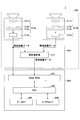
- FIG. 2 is a diagram showing the configuration of the imaging unit 500 and the image analysis unit 600.
- the imaging unit 500 is configured of a stereo camera provided with two imaging units 510a and 510b as imaging means, and the two imaging units 510a and 510b are the same.
- the respective imaging units 510a and 510b respectively include imaging lenses 511a and 511b, sensor substrates 514a and 514b including image sensors 513a and 513b on which light receiving elements are two-dimensionally arranged, and analog signals output from the sensor substrates 514a and 514b.
- Electric signal (electrical signal corresponding to the amount of light received by each light receiving element on the image sensor 513a, 513b) is converted into a digital electric signal, and it is composed of signal processing units 515a, 515b for generating and outputting ing.
- the imaging unit 500 outputs luminance image data and parallax image data.
- the imaging unit 500 further includes a processing hardware unit 510 including an FPGA (Field-Programmable Gate Array) or the like.
- the processing hardware unit 510 calculates the parallax values of the corresponding image portions between the images captured by the imaging units 510a and 510b.
- a parallax calculator 511 is provided as parallax image information generation means for calculating.
- the parallax value referred to here is a comparison image with respect to an image portion on the reference image corresponding to the same point in the imaging region, with one of the images taken by each of the imaging units 510a and 510b as the reference image and the other as the comparison image.
- the positional displacement amount of the upper image portion is calculated as the parallax value of the image portion.
- the image analysis unit 600 includes an image processing board or the like, and stores the luminance image data and the parallax image data output from the imaging unit 500 as storage means 601 including RAM, ROM, etc.
- a central processing unit (CPU) 602 that executes a computer program for performing parallax calculation control and the like, a data I / F (interface) 603, and a serial I / F 604 are provided.
- the FPGA that configures the processing hardware unit 510 performs processing that requires real-time processing on image data, such as gamma correction, distortion correction (parallelization of right and left captured images), and parallax calculation using block matching to generate a parallax image. And the like, and performs processing such as writing out in the RAM of the image analysis unit 600.
- the CPU 602 of the image analysis unit 600 is responsible for control of the image sensor controller of each of the imaging units 510a and 510b and overall control of the image processing board, detection processing of the three-dimensional shape of the road surface, guardrails, and other various objects (identification target Load a program to execute object detection processing etc.
- the processing result is data I / F 603 or serial I / F Output from F604 to the outside.
- vehicle operation information such as the vehicle speed, acceleration (acceleration mainly generated in the front and rear direction of the vehicle) of the vehicle 100, steering angle, yaw rate etc. It can also be used as a processing parameter.
- the data output to the outside is used as input data for performing control (brake control, vehicle speed control, warning control, etc.) of various devices of the host vehicle 100.
- the imaging unit 500 and the image analysis unit 600 may be configured as an imaging device 2 that is an integral device.
- FIG. 3 is a functional block diagram of the in-vehicle device control system 1 realized by the processing hardware unit 510, the image analysis unit 600, and the vehicle travel control unit 104 in FIG.
- the functional unit realized by the image analysis unit 600 is realized by processing that one or more programs installed in the image analysis unit 600 causes the CPU 602 of the image analysis unit 600 to execute.
- the parallax image generation unit 11 performs parallax image generation processing for generating parallax image data (parallax image information).
- the parallax image generation unit 11 is configured of, for example, a parallax calculation unit 511 (FIG. 2).
- luminance image data of one of the two imaging units 510a and 510b is used as reference image data, and luminance image data of the other imaging unit 510b is used as comparison image data.
- the disparity between the two is calculated using this to generate and output disparity image data.
- the parallax image data represents a parallax image in which pixel values corresponding to the parallax value d calculated for each image portion on the reference image data are represented as pixel values of the respective image portions.
- the parallax image generation unit 11 defines a block including a plurality of pixels (for example, 16 pixels ⁇ 1 pixel) centering on one target pixel for a row of reference image data.
- a block of the same size as the block of the defined reference image data is shifted by one pixel in the horizontal line direction (x direction) to indicate the feature of the pixel value of the block defined in the reference image data.
- a correlation value indicating a correlation between the feature amount and the feature amount indicating the feature of the pixel value of each block in the comparison image data is calculated.
- a matching process is performed to select a block of comparison image data that is most correlated with the block of reference image data among the blocks of comparison image data. Thereafter, the amount of positional deviation between the target pixel of the block of the reference image data and the corresponding pixel of the block of the comparison image data selected in the matching process is calculated as the parallax value d. It is possible to obtain parallax image data by performing such a process of calculating the parallax value d for the entire area of the reference image data or a specific area.
- the value (brightness value) of each pixel in the block can be used as the feature amount of the block used for the matching process, and the correlation value can be, for example, the value of each pixel in the block of the reference image data (brightness A sum of absolute values of differences between the values) and the values (brightness values) of the respective pixels in the block of the comparison image data respectively corresponding to these pixels can be used. In this case, it can be said that the block with the smallest total sum is most correlated.
- the matching processing in the parallax image generation unit 11 is realized by hardware processing, for example, SSD (Sum of Squared Difference), ZSSD (Zero-mean Sum of Squared Difference), SAD (Sum of Absolute Difference), ZSAD (Sum of Absolute Difference).
- SSD Sud of Squared Difference
- ZSSD Zero-mean Sum of Squared Difference
- SAD Sum of Absolute Difference
- ZSAD Quantum of Absolute Difference
- a method such as Zero-mean Sum of Absolute Difference, NCC (Normalized cross correlation), or the like can be used.
- NCC Normalized cross correlation
- the estimation method for example, an equiangular linear method, a quadratic curve method or the like can be used.
- V map generation unit 12 executes V map generation processing for generating a V map (V-Disparity Map, an example of “vertical direction distribution data”) based on parallax pixel data.
- V-Disparity Map an example of “vertical direction distribution data”
- Each piece of parallax pixel data included in parallax image data is indicated by a set (x, y, d) of an x-direction position, a y-direction position, and a parallax value d.
- This is converted into three-dimensional coordinate information (d, y, f) with d set on the X axis, y on the Y axis, and frequency f on the Z axis, or this three-dimensional coordinate information (d, y, f) , And three-dimensional coordinate information (d, y, f) limited to information exceeding a predetermined frequency threshold is generated as disparity histogram information.
- the parallax histogram information of the present embodiment is composed of three-dimensional coordinate information (d, y, f), and a distribution of this three-dimensional histogram information in an XY two-dimensional coordinate system is called a V map.
- the V map generation unit 12 calculates a disparity value frequency distribution for each row region obtained by dividing the disparity image in the vertical direction.
- Information indicating this disparity value frequency distribution is disparity histogram information.
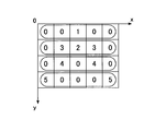
- FIGS. 4A and 4B are diagrams for explaining parallax image data and a V map generated from the parallax image data.
- FIG. 4A is a view showing an example of the parallax value distribution of the parallax image
- FIG. 4B is a view showing a V map showing the parallax value frequency distribution for each row of the parallax image of FIG. 4A.
- the V map generation unit 12 calculates a parallax value frequency distribution which is a distribution of the number of data of each parallax value for each row, This is output as disparity histogram information.
- a V map as shown in FIG. 4B can be obtained.
- This V map can also be expressed as an image in which pixels having pixel values according to the frequency f are distributed on the two-dimensional orthogonal coordinate system.
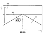
- FIG. 5A and FIG. 5B are diagrams showing an image example of a captured image as a reference image captured by one imaging unit, and a V map corresponding to the captured image.
- FIG. 5A is a captured image
- FIG. 5B is a V map. That is, the V map shown in FIG. 5B is generated from the photographed image as shown in FIG. 5A.
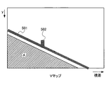
- the V map since parallax is not detected in the area below the road surface, parallax is not counted in the hatched area A.
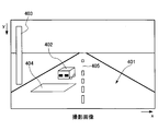
- working the preceding vehicle 402 which exists in front of the own vehicle, and the utility pole 403 which exists out of the road are shown.
- the V map shown in FIG. 5B there are a road surface 501, a leading vehicle 502, and a telephone pole 503 corresponding to the image example.
- the front road surface of the host vehicle is a relatively flat road surface, that is, the front road surface of the host vehicle is obtained by extending the plane parallel to the road surface portion directly below the host vehicle to the front of the host vehicle. It is a case where it corresponds to a reference road surface (virtual reference movement surface).
- the high frequency points are distributed in a substantially straight line with an inclination such that the parallax value d becomes smaller toward the upper side of the image. Pixels showing such a distribution are present at approximately the same distance in each row on the parallax image and have the highest occupancy rate, and pixels that project an object of identification whose distance increases continuously as they move upward in the image It can be said that
- the parallax value d of the road surface decreases toward the upper side of the image as shown in FIG. 5A.
- the high-frequency points distributed in a substantially straight line on the V map correspond to the features possessed by the pixels projecting the road surface (moving surface). Therefore, it is possible to estimate that the pixels of the point distributed on the approximate straight line obtained by straight line approximation of the high frequency points on the V map or in the vicinity thereof are the pixels showing the road surface with high accuracy. Further, the distance to the road surface portion shown in each pixel can be determined with high accuracy from the parallax value d of the corresponding point on the approximate straight line.
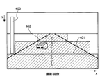
- FIGS. 6A and 6B are diagrams showing an image example of a captured image as a reference image captured by one imaging unit and a V map of a predetermined region corresponding to the captured image.
- the V map generation unit 12 may generate a V map using all pixels in a parallax image, or a predetermined region (for example, FIG. 6A is an example of a captured image that is a basis of the parallax image).
- the V map may be generated using only the pixels of the area where the road surface may appear. For example, the road surface narrows toward the vanishing point as it gets farther, so an area may be set according to the width of the road surface as shown in FIG. 6A. This makes it possible to prevent noise from an object (for example, the telephone pole 403) located in an area other than the area where the road surface can be captured from being mixed in the V map.
- FIGS. 7A and 7B are diagrams showing an image example of a captured image as a reference image captured by one of the imaging units when noise is generated, and a V map corresponding to the captured image.
- FIG. 7A compared with the example of FIG. 6A, a reflection 404 due to a puddle or the like and a break 405 of a white line are shown in FIG. 7A.
- the interruption of the white line occurs, for example, when the white line disappears on an old road or when the interval between the white lines is long.
- the V map shown in FIG. 7B includes noise due to reflection 504 due to a water pool or the like and break 505 of the white line.
- pixels (disparity points) having a frequency value of a predetermined value (for example, 1) or more are dispersed in the horizontal axis direction (the direction of the disparity value) by the reflection 504 by a pool or the like.
- the road surface estimation unit 13 estimates (detects) the road surface based on the parallax image generated by the parallax image generation unit 11. As shown in FIG. 3, the road surface estimation unit 13 includes a first road surface estimation unit 13 a and a second road surface estimation unit 13 b. In addition, although the road surface estimation part 13 demonstrates the example which estimates a road surface by two systems below, the road surface estimation part 13 may estimate a road surface by three or more systems.
- FIG. 8 is a functional block diagram showing an example of the first road surface estimation unit 13a.
- the first road surface estimation unit 13 a includes a sample point extraction unit 131, an outlier removal unit 132, a road surface shape detection unit 133, a road surface supplementation unit 134, a smoothing processing unit 135, a road surface determination unit 136, and a road surface height table calculation unit 15. Have.
- sample point extraction processing The sample point extraction unit 131 extracts sample points used for estimation of the road surface from the V map generated by the V map generation unit 12.
- the V map is divided into a plurality of segments according to a parallax value (distance value from the host vehicle) and sample point extraction processing, road surface shape detection processing, etc. described later are performed.
- the sample point extraction process or the road surface shape detection process may be performed without dividing the V map.
- FIG. 9 is a flowchart showing an example of sample point extraction processing.
- the sample point extraction unit 131 divides the V map into a plurality of segments according to the value of disparity that is the horizontal axis of the V map (step S11).
- the sample point extraction unit 131 sets a range (search range) for searching for sample points to be extracted in a segment (first segment) having the largest parallax value (the shortest distance from the host vehicle) Step S12).
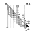
- FIG. 10 is a diagram for explaining an example of processing for extracting sample points from the first segment.
- the sample point extraction unit 131 uses a start point position 552 of a straight line corresponding to the default road surface 551 (“predetermined road surface”) as a reference point, and sets a predetermined range corresponding to the reference point. It is set as a search area 553 of sample points.
- the data of a default road surface are preset, for example, when a stereo camera is attached to the own vehicle. For example, flat road surface data may be set.
- the sample point extraction unit 131 is a search area 553 between two straight lines 554 and 555 starting from the reference point and extending to the next segment at a predetermined angle. It may be In this case, the sample point extraction unit 131 may determine the two straight lines 554 and 555 in accordance with the angle at which the road surface can tilt. For example, the lower straight line 554 is determined according to the inclination of the descending road surface which can be photographed by a stereo camera, and the upper straight line 555 is a preset upper limit of the ascending road inclination restricted by law. It may be determined correspondingly. Alternatively, the sample point extraction unit 131 may set the search area 553 to, for example, a rectangular area.
- the sample point extraction unit 131 extracts sample points from the pixels included in the search range (step S13).
- the sample point extraction unit 131 may extract, for example, one or more sample points for each coordinate position of each parallax value d from the pixels included in the search range.
- the sample point extraction unit 131 may extract, as a sample point, the most frequent point with the highest frequency at the coordinate position of each disparity value d from the pixels included in the search range.
- a plurality of coordinate positions including each parallax value d (for example, coordinate positions of each parallax value d, and the left and right of each parallax value d) among the pixels included in the search range
- the most frequent mode point in at least one of one or more coordinate positions may be extracted as a sampling point.
- the outlier removal unit 132, the road surface shape detection unit 133, and the road surface supplementation unit 134 detect the road surface in the segment including the sample points based on the sample points extracted in step S13 (step S14).
- the road surface selected by the road surface determination unit 14 described later may be the road surface in the segment.
- the following is detected based on the road surface detected by the second road surface estimation unit 13b:
- the road surface in the segment can be detected.
- the sample point extraction unit 131 determines whether there is a next segment (for example, a segment with the next smallest parallax value) (step S15), and if there is no next segment (NO in step S15), the process ends. .
- step S15 If there is a next segment (YES in step S15), the sample point extraction unit 131 acquires the end point position of the road surface detected in step S14 (step S16).
- the sample point extraction unit 131 sets a search range in the next segment based on the end point position of the road surface acquired in step S15 (step S17), and the process proceeds to step S13.
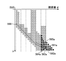
- FIGS. 11A and 11B are diagrams for explaining an example of processing for extracting sample points from the second segments other than the first segment.
- the sample point extraction unit 131 for example, in the second segment, the end point position (the road surface 561 of the previous segment) of the road surface 561 of the previous segment (the segment adjacent to the second segment having already detected the road surface) A position in contact with the segment 2) is a reference point 562. Then, as in the case of step S12 shown in FIG. 10, the sample point extraction unit 131 sets a predetermined range corresponding to the reference point 562 as a search area 563 of sample points.
- the sample point extraction unit 131 searches the area between the two straight lines 564 and 565 starting from the reference point and between the two straight lines 564 and 565 extending to the adjacent segment at a predetermined angle. It may be In this case, the sample point extraction unit 131 may determine the two straight lines 564 and 565 in accordance with the angle at which the road surface can tilt. Alternatively, the sample point extraction unit 131 may set the search area 563 to a rectangular area having a height corresponding to the y coordinate of the reference point 562 as shown in FIG. 11B, for example.
- FIG. 12 is a diagram for explaining another example of the process of extracting sample points from the second segment.
- the sample point extraction unit 131 sets the end point position of the road surface (history road surface) 561a of the segment adjacent to the second segment detected in the frame of the previous parallax image as the reference point 562a. . Then, the sample point extraction unit 131 sets a predetermined range corresponding to the reference point 562a as a search area 563a of sample points.
- the difference between the default road surface and the correct (actual) road surface 566 is large, for example, in the case of a downhill road surface, it is detected in the first segment as shown in FIGS. 11A and 11B.
- a more appropriate search range can be set as compared with the case where the end point position of the road surface is used as the reference point.
- the history road surface may use the road surface detected in the previous one frame, or may use the average of the road surfaces detected in the plurality of previous frames.
- the outlier removal unit 132 excludes points that are not suitable for linear approximation.
- FIG. 13 is a flowchart showing an example of the outlier removal process.
- FIG. 14 is a diagram for explaining outlier removal processing.
- the outlier removal unit 132 calculates an approximate straight line from the sample points of each segment extracted by the sample point extraction unit 131 or the sample points of all the segments (step S20).
- the outlier removal unit 132 calculates an approximate straight line using, for example, the least squares method.
- the approximate straight line 541 is calculated in step S20 of FIG.
- the outlier removal unit 132 calculates a threshold according to the value of the X coordinate (step S21).
- a value D of a predetermined X coordinate for example, a parallax value corresponding to a distance of 50 m from the host vehicle
- D far above the target distance from the host vehicle
- the above is taken as ⁇ . This is to loose the threshold for removal on a road surface at a position where the parallax value is small, that is, the distance from the host vehicle is long, because the error when measuring with the stereo camera is large.
- the outlier removal unit 132 removes a sample point at which the Euclidean distance is greater than or equal to the threshold calculated in step S21 with respect to the calculated approximate straight line (step S22).
- sample points 542 which are equal to or larger than D and separated by a predetermined threshold value ⁇ or more are removed.
- the road surface shape detection unit 133 extracts the shape of the road surface based on the sample points extracted by the sample point extraction unit 131 and not removed by the outlier removal unit 132 from each segment of the V map generated by the V map generation unit 12 Detect (Position, Height).
- the road surface shape detection unit 133 calculates an approximate straight line from sample points of each segment by, for example, the least square method, and detects (estimates) the calculated approximate straight line as a road surface.
- Road surface supplementary processing The road surface supplement unit 134 determines whether the road surface detected (estimated) by the road surface shape detection unit 133 or the road surface selected by the road surface determination unit 14 described later is inappropriate, and determines that the road surface is inappropriate. , Supplement the road surface.
- the road surface supplementing unit 134 determines whether an inappropriate road surface that can not be photographed by the stereo camera has been estimated by the noise. Then, if it is determined that an inappropriate road surface has been estimated, the road surface supplementing unit 134 supplements (interpolates) the inappropriate road surface based on data of a default road surface or a road surface estimated in a previous frame.
- the road surface supplement unit 134 when data of a road surface that is steeply rising to the right is detected in the V map in the V map, the road surface supplement unit 134 has a slope that increases as the distance from the host vehicle increases. It is determined that the road surface is a steep downhill road. Then, the road surface supplementing unit 134 removes the data of the road surface and supplements it with data of the default road surface etc. instead.
- the smoothing processing unit 135 corrects each road surface estimated in each segment so that each road surface is continuous.
- the smoothing processing unit 135 sets the inclination and intercept of each road surface such that the end point (end point) of one road surface and the start point (end point) of the other road surface of the road surfaces respectively estimated in two adjacent segments coincide with each other.
- the second road surface estimation unit 13 b estimates the road surface by a method different from that of the first road surface estimation unit 13 a.
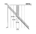
- FIG. 15 is a diagram for explaining the road surface estimation processing by the second road surface estimation unit 13b.
- the second road surface estimation unit 13b extracts, as sample points 571A,..., 571N, for example, among the pixels of parallax points for each parallax value d in the V map, the second road surface estimation unit 13b extracts the pixels. Do. Then, based on the extracted sample points, for example, the second road surface 572b is extracted by processing such as the above-described outlier removal processing. In this case, if the lowest point is noise, there is a possibility that an erroneous road surface may be estimated, so the frequency of each coordinate may be used to remove the noise.
- the road surface can be appropriately detected, for example, when it is not rainy (when in good weather) (scene), because it is not affected by the parallax of an object present on the road surface.
- the road surface estimation method by the first road surface estimation unit 13a or the second road surface estimation unit 13b is not limited to the above-described example.
- the road surface in the current frame may be a road surface based on, for example, an average of the plurality of road surfaces estimated based on a plurality of frames of the previous parallax image.
- the V map may be divided into a plurality of segments, and the road surface may be estimated by, for example, extending the road surface estimated in one segment to another segment based on the road surface estimated in one segment.
- it may be approximated with a curve.
- the road surface determination unit 14 determines data of a road surface to be adopted based on the road surfaces estimated by the first road surface estimation unit 13a and the second road surface estimation unit 13b.
- the road surface determination unit 14 selects one road surface from the road surfaces estimated by the first road surface estimation unit 13a and the second road surface estimation unit 13b. Alternatively, the road surface determination unit 14 may perform predetermined weighting on the road surfaces respectively estimated by the first road surface estimation unit 13a and the second road surface estimation unit 13b and combine them. The road surface determination unit 14 may use, for example, a value corresponding to the number of sample points extracted by the first road surface estimation unit 13a and the second road surface estimation unit 13b as a predetermined weighting value.
- FIG. 16 is a flowchart showing an example of the road surface determination process.
- the road surface determination unit 14 acquires the road surface (first road surface) for each segment estimated by the first road surface estimation unit 13a (step S31).
- the road surface determination unit 14 acquires the road surface (second road surface) for each segment estimated by the second road surface estimation unit 13b (step S32).
- the road surface determination unit 14 calculates the inclination (gradient) of the first road surface and the inclination of the second road surface in each segment (step S33).
- the road surface determination unit 14 determines that the difference between the inclination of the first road surface and the inclination of the second road surface in the target segment (one segment included in each segment) is equal to or greater than a predetermined threshold Or not (step S34).
- the road surface determination unit 14 selects one of the first road surface and the second road surface. The road surface with the smaller inclination is selected (step S35), and the process is ended.
- the road surface determination unit 14 selects one of the first road surface and the second road surface. The road surface with the larger inclination is selected (step S36), and the process ends.
- 17A and 17B illustrate an example of the road surface determination process.
- FIG. 17A shows the case where the first road surface 572a in a certain segment 573 estimated by the first road surface estimation unit 13a is pulled upward by the parallax of an object such as a preceding vehicle located on the road surface. It is an example.
- the road surface determination unit 14 determines that the difference between the inclination of the first road surface and the inclination of the second road surface is equal to or greater than a predetermined threshold value in step S34 of FIG. 16, for example, when the following conditions are satisfied. Do.
- H1 is the difference between the Y coordinate of the end point of the first road surface 572a in a certain segment 573 and the Y coordinate of the end point of the second road surface 572b
- H2 is the difference between the Y coordinate of the starting point of the first road surface 572a in the segment and the Y coordinate of the starting point of the second road surface 572b.
- a and B are predetermined constants.
- step S34 of FIG. 16 for example, the first road surface is higher than the second road surface, and the inclination of the first road surface in the target segment and the second road surface are determined in step S34 of FIG. It may be determined whether or not the difference with the slope of is greater than or equal to a predetermined threshold.
- the road surface determination unit 14 selects the road surface based on the upper and lower sides of the Y coordinate of the end point in the target segment, for example. May be
- the first road surface a pixel having a high value of frequent points with respect to each parallax value d in the V map is extracted as a sample point
- Y coordinate is the most for each parallax value d in the V map
- the road surface determination unit 14 selects the road surface to be adopted based on the inclination of the first road surface and the second road surface. Instead of or in addition to this, the road surface determination unit 14 selects the road surface to be adopted based on the respective reliabilities (correlation coefficients) when the first road surface and the second road surface are estimated by linear approximation.
- the road surface determination unit 14 selects a road surface to be adopted according to the score of the first road surface and the score of the second road surface.
- the road surface height table calculation unit 15 calculates the road surface height (relative height with respect to the road surface portion immediately below the own vehicle) based on the road surface in each segment corrected by the smoothing processing unit 135 and makes it into a table Road surface height table calculation processing is performed.
- the road surface height table calculation unit 15 calculates the distance to each road surface portion shown in each row area (each position in the vertical direction of the image) on the captured image from the information of the road surface in each segment. In addition, each surface portion in the traveling direction of the subject vehicle of the virtual plane extending forward to the traveling direction of the subject vehicle so that the road surface portion located directly below the subject vehicle is parallel to the plane is shown in any row region in the captured image.
- the virtual plane reference road surface
- the road surface height table calculation unit 15 can obtain the height of each road surface portion ahead of the host vehicle by comparing the road surface in each segment with the reference straight line.
- the road surface height table calculation unit 15 tabulates the height of each road surface portion obtained from the approximate straight line with respect to a necessary parallax range.
- the height from the road surface of the object shown in the captured image portion corresponding to the point where the Y-axis position is y ′ at a certain parallax value d is the Y-axis position on the road surface at the parallax value d as y0. It can be calculated from (y'-y0).
- the height H from the road surface for the object corresponding to the coordinates (d, y ′) on the V map can be calculated by the following equation.
- “f” is the focal length of the camera (y′ ⁇ y0) It is a value converted to the same unit as the unit.
- BF is a value obtained by multiplying the base length of the stereo camera and the focal length
- “offset” is a parallax value when an object at infinity is photographed.
- the clustering unit 16 sets a pair (x, y, d) of an x-direction position, a y-direction position, and a parallax value d in each parallax pixel data included in parallax image data to the x axis along the x axis and d and z along the y axis.
- the frequency is set on the axis, and XY two-dimensional histogram information (frequency U map) is created.
- the clustering unit 16 generates parallax images whose height H from the road surface is in a predetermined height range (for example, 20 cm to 3 m) based on the heights of the road surface portions tabulated by the road surface height table calculation unit 15. Create a frequency U map only for points (x, y, d). In this case, an object present in the predetermined height range can be appropriately extracted from the road surface.
- a predetermined height range for example, 20 cm to 3 m
- the clustering unit 16 detects, in the frequency U map, an area where the frequency is higher than a predetermined value and in which parallax is dense as an area of the object, and based on the coordinates on the parallax image and the actual size (size) of the object. It provides individual information such as the predicted type of object (person or pedestrian).
- the rejection unit 17 rejects information of an object that is not a recognition target based on the parallax image, the frequency U map, and the individual information of the object.
- the tracking unit 18 determines whether or not the object to be tracked is a tracking object when the detected object appears continuously in frames of a plurality of parallax images.
- Driving support control The control unit 19 performs driving support control such as, for example, notifying a driver of the own vehicle 100 of a warning or controlling a steering wheel or a brake of the own vehicle based on the detection result of the object by the clustering unit 16.
- the road surface determination unit 14 selects the road surface to be adopted based on the inclinations of the first road surface and the second road surface.
- the road surface determination unit 14 selects a road surface to be adopted based on the distribution shape and the number of parallax points in a predetermined area including the first road surface and the second road surface.
- the second embodiment is the same as the first embodiment except for a part of the second embodiment, so the description will be appropriately omitted.
- FIG. 18 is a diagram showing an example of a flowchart of road surface determination processing according to the second embodiment.
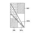
- FIG. 19A and FIG. 19B are diagrams showing an example of an area such as a rectangle including the first road surface and the second road surface.
- the road surface determination unit 14 includes, for example, a rectangle including the first road surface estimated by the first road surface estimation unit 13a and the second road surface estimated by the second road surface estimation unit 13b. Area is set (step S201).
- the road surface determination unit 14 calculates the number of parallax points included in the set area (step S202).
- the road surface determination unit 14 calculates the density of parallax points in the set area (step S203). For example, the road surface determination unit 14 calculates the density by dividing the parallax point in the set area by the area of the set area.
- the road surface determination unit 14 determines whether the density of parallax points in the set area is equal to or more than a predetermined threshold (step S204). In addition, it may be determined whether it is more than a predetermined threshold value using the number of parallax points when the area of the area to be set is fixed instead of the density of the parallax points.
- the road surface determination unit 14 selects the first road surface 582a existing in the upper side where the height in the vertical direction is high (step S205), and ends the process.
- the road surface determination unit 14 acquires the distribution shape of the parallax points included in the set area (step S206).
- the road surface determination unit 14 determines whether the distribution shape of the parallax points included in the set area is a predetermined shape (step S207).
- the predetermined shape is, for example, a shape in which the distribution of parallax points of at least one of the upper right 583 and the lower left 584 in the set area is equal to or less than a predetermined value.
- the road surface determination unit 14 determines that the shape is a predetermined shape, for example, when the density or number of at least one of the upper right 583 and the lower left 584 in the set area is less than or equal to a predetermined value. Do.
- the road surface determination unit 14 selects the second road surface 582b present below (step S208), and ends the process.
- the road surface determination unit 14 selects the first road surface as in step S205, for example, and ends the process. .
- the road surface determination process in the first embodiment described above may be executed to select the road surface.
- the road surface determination unit 14 performs image recognition on a predetermined area of a captured image (luminance image) or a parallax image, and selects a road surface to be adopted based on the result of the image recognition. Note that the third embodiment is the same as the first embodiment except for a part thereof, so the description will be appropriately omitted.
- FIG. 20 is a diagram showing an example of a flowchart of road surface determination processing according to the third embodiment.
- the road surface determination unit 14 sets each segment in an area where the road surface can be captured in the captured image or the parallax image (step S301).
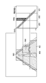
- FIG. 21 is a diagram for explaining the correspondence between a captured image or a parallax image and a V map.
- FIG. 21 shows an example in which the area where the road surface can be photographed is divided into three segments 591, 592, and 593.
- the road surface determination unit 14 recognizes each segment of the captured image or the parallax image (step S302).
- any method may be used as the method of image recognition in step S302.
- a template for an object such as a vehicle, a person, a road surface, or a raindrop may be prepared in advance, and the object may be recognized by template matching.
- each segment may be divided and the recognition process may be sequentially performed while raster scanning is performed.
- recognition accuracy can be improved.
- the road surface determination unit 14 determines whether it is rainy weather (a scene of rain) based on the result of the image recognition in step S302 (step S303).
- step S303 If the result of the image recognition is rainy weather (YES in step S303), there is a possibility that the second road surface existing below is affected by noise due to water pooling during rainy weather. Therefore, the road surface determination unit 14 selects the first road surface existing above (step S304), and ends the processing.
- the road surface determination unit 14 recognizes the image of an object (594 in FIG. 21) in each segment based on the result of the image recognition in step S302. It is determined whether it has been done (step S305).
- step S305 When an image of an object such as a leading vehicle is recognized (YES in step S305), there is a possibility that the first road surface existing above is pulled upward by the parallax of the object (594a in FIG. 21). Therefore, the road surface determination unit 14 selects the second road surface 582b existing below in the segment in which the image of the object such as the leading vehicle is recognized (step S306), and the process ends.
- the road surface determination unit 14 selects the first road surface as in step S204, for example, and ends the process.
- the road surface determination process in each embodiment described above may be executed to select a road surface.
- the plurality of road surfaces are estimated based on the V map, and the road surface is determined based on the plurality of estimated road surfaces. Therefore, it is possible to improve the accuracy of detecting the road surface.
- a distance image may be generated by integrating distance information generated using a detection device such as a millimeter wave radar or laser radar with respect to parallax images generated using a stereo camera.
- the detection accuracy may be further enhanced by using a stereo camera and a detection device such as a millimeter wave radar or a laser radar in combination and combining it with the above-described detection result of an object by the stereo camera.
- the functional units may not be provided.
- each functional unit of the processing hardware unit 510, the image analysis unit 600, and the vehicle travel control unit 104 may be realized by hardware, or the CPU executes a program stored in the storage device.
- the configuration may be realized by This program may be recorded in a computer readable recording medium and distributed by a file in an installable format or an executable format.
- a CD-R Compact Disc Recordable
- DVD Digital Versatile Disk
- Blu-ray Disc etc.
- recording media such as CD-ROM in which each program is stored, and HD 504 in which these programs are stored can be provided domestically or abroad as a program product (Program Product).
- In-vehicle device control system (an example of “device control system") 100 self-vehicle 101 imaging unit 103 display monitor 106 vehicle travel control unit (an example of “control unit”) 11 Parallax image generator (an example of “distance image generator”) 12 V map generation unit (an example of “generation unit”) 13 Road surface estimation unit (an example of “estimation unit”) 13a first road surface estimation unit 13b second road surface estimation unit 131 sample point extraction unit 132 outlier removal unit 133 road surface shape detection unit 134 road surface supplementation unit 135 smoothing processing unit 14 road surface determination unit (an example of "determination unit”) 15 road surface height table calculation unit 16 clustering unit (an example of "object detection unit”) 17 rejection unit 18 tracking unit 19 control unit 2 imaging device 510 a, 510 b imaging unit 510 processing hardware unit 600 image analysis unit (an example of “image processing device”)
Landscapes
- Engineering & Computer Science (AREA)
- Physics & Mathematics (AREA)
- General Physics & Mathematics (AREA)
- Theoretical Computer Science (AREA)
- Computer Vision & Pattern Recognition (AREA)
- Multimedia (AREA)
- Electromagnetism (AREA)
- Aviation & Aerospace Engineering (AREA)
- Radar, Positioning & Navigation (AREA)
- Remote Sensing (AREA)
- Automation & Control Theory (AREA)
- Image Analysis (AREA)
- Traffic Control Systems (AREA)
- Image Processing (AREA)
Abstract
Description
[第1の実施形態]
〈車載機器制御システムの構成〉
図1は、本発明の実施形態に係る移動体機器制御システムとしての車載機器制御システムの構成を示す図である。
図2は、撮像ユニット500及び画像解析ユニット600の構成を示す図である。
視差画像生成部11は、視差画像データ(視差画像情報)を生成する視差画像生成処理を行う。なお、視差画像生成部11は、例えば視差演算部511(図2)によって構成される。
Vマップ生成部12は、視差画素データに基づき、Vマップ(V-Disparity Map、「垂直方向分布データ」の一例)を生成するVマップ生成処理を実行する。視差画像データに含まれる各視差画素データは、x方向位置とy方向位置と視差値dとの組(x,y,d)で示される。これを、X軸にd、Y軸にy、Z軸に頻度fを設定した三次元座標情報(d,y,f)に変換したもの、又はこの三次元座標情報(d,y,f)から所定の頻度閾値を超える情報に限定した三次元座標情報(d,y,f)を、視差ヒストグラム情報として生成する。本実施形態の視差ヒストグラム情報は、三次元座標情報(d,y,f)からなり、この三次元ヒストグラム情報をX-Yの2次元座標系に分布させたものを、Vマップと呼ぶ。
路面推定部13は、視差画像生成部11により生成された視差画像に基づき、路面を推定(検出)する。図3に示すように、路面推定部13は、第1の路面推定部13a、及び第2の路面推定部13bを有する。なお、以下では、路面推定部13は、2つの方式で路面を推定する例について説明するが、路面推定部13は、3以上の方式で路面を推定してもよい。
第1の路面推定部13aは、標本点抽出部131、外れ点除去部132、路面形状検出部133、路面補足部134、スムージング処理部135、路面決定部136、及び路面高さテーブル算出部15を有する。
標本点抽出部131は、Vマップ生成部12により生成されたVマップから、路面の推定に用いる標本点を抽出する。
図12は、第2のセグメントから、標本点を抽出する処理の他の例を説明する図である。
外れ点除去部132は、標本点抽出部131により抽出された標本点のうち、直線近似に適さない点を除外する。
路面形状検出部133は、Vマップ生成部12により生成されたVマップの各セグメントから、標本点抽出部131により抽出され、外れ点除去部132により除去されていない標本点に基づき、路面の形状(位置、高さ)を検出する。
路面補足部134は、路面形状検出部133により検出(推定)された路面、または、後述する路面決定部14により選択された路面が不適切か否かを判定し、不適切と判定した場合は、路面を補足する。
スムージング処理部135は、各セグメントで推定された各路面を、当該各路面が連続するように修正する。スムージング処理部135は、隣り合う2つのセグメントにおいてそれぞれ推定された各路面のうち、一方の路面の終点(端点)と、他方の路面の始点(端点)が一致するよう、各路面の傾きと切片を変更する。
第2の路面推定部13bは、第1の路面推定部13aとは異なる方式により、路面を推定する。
路面決定部14は、第1の路面推定部13a、及び第2の路面推定部13bにより各々推定された路面に基づき、採用する路面のデータを決定する。
ここで、図17Bに示すように、H1は、あるセグメント573における第1の路面572aの終点のY座標と、第2の路面572bの終点のY座標の差である。H2は、当該あるセグメントにおける第1の路面572aの始点のY座標と、第2の路面572bの始点のY座標の差である。A及びBは所定の定数である。
あるセグメントにおける第1の路面と第2の路面の傾きが異なる場合、上述した第1の路面が、路面上に位置する先行車両等の物体の視差により、上方向に引っ張られている可能性がある。または、上述した第2の路面が、図7Bに示すように、水たまり等による照り返し504により、下方向に引っ張られている可能性がある。
上述した実施形態では、路面決定部14は、第1の路面と第2の路面の傾きに基づいて、採用する路面を選択していた。これに代えて、または加えて、路面決定部14は、直線近似により第1の路面と第2の路面を推定した際の各々の信頼度(相関係数)に基づいて、採用する路面を選択してもよい。この場合、例えば、第1の路面推定部13a、及び第2の路面推定部13bは、抽出した各標本点に基づいて最小二乗法により近似直線を算出した際、当該近似直線と各標本点との相関係数に基づくスコアを算出する。そして、路面決定部14は、第1の路面のスコアと第2の路面のスコアに応じて、採用する路面を選択する。この変形例を、上述した路面決定処理に加える場合は、例えば、図16のステップS36の処理に代えて、この変形例に係る処理を実行してもよい。
路面高さテーブル算出部15は、スムージング処理部135にて修正された各セグメントにおける路面に基づいて、路面高さ(自車両の真下の路面部分に対する相対的な高さ)を算出してテーブル化する路面高さテーブル算出処理を行う。
〈クラスタリング、棄却、トラッキング〉
クラスタリング部16は、視差画像データに含まれる各視差画素データにおけるx方向位置とy方向位置と視差値dとの組(x,y,d)を、X軸にx、Y軸にd、Z軸に頻度を設定し、X-Yの2次元ヒストグラム情報(頻度Uマップ)を作成する。
制御部19は、クラスタリング部16による、物体の検出結果に基づいて、例えば、自車両100の運転者へ警告を報知したり、自車両のハンドルやブレーキを制御したりするなどの走行支援制御を行う。
[第2の実施形態]
第1の実施形態では、路面決定部14は、第1の路面と第2の路面の傾きに基づいて、採用する路面を選択していた。第2の実施形態では、路面決定部14は、第1の路面と第2の路面を含む所定の領域における視差点の分布形状や数に基づき、採用する路面を選択する。なお、第2の実施形態は一部を除いて第1の実施形態と同様であるため、適宜説明を省略する。
第2の実施形態によれば、第1の実施形態と同様の効果を得られる。
[第3の実施形態]
第3の実施形態では、路面決定部14は、撮影画像(輝度画像)または視差画像の所定領域内を画像認識し、画像認識の結果に基づいて、採用する路面を選択する。なお、第3の実施形態は一部を除いて第1の実施形態と同様であるため、適宜説明を省略する。
雨天時の路面の照り返し等により、視差にノイズが発生すると、推定される路面が正解に対して低すぎたり、逆に高すぎたりする問題が発生する。推定される路面が低すぎる場合、路面の一部を障害物と誤認識する場合がある。推定される路面が高すぎる場合、推定される路面よりも低い障害物等を検出できない場合がある。
100 自車両
101 撮像ユニット
103 表示モニタ
106 車両走行制御ユニット(「制御部」の一例)
11 視差画像生成部(「距離画像生成部」の一例)
12 Vマップ生成部(「生成部」の一例)
13 路面推定部(「推定部」の一例)
13a 第1の路面推定部
13b 第2の路面推定部
131 標本点抽出部
132 外れ点除去部
133 路面形状検出部
134 路面補足部
135 スムージング処理部
14 路面決定部(「決定部」の一例)
15 路面高さテーブル算出部
16 クラスタリング部(「物体検出部」の一例)
17 棄却部
18 トラッキング部
19 制御部
2 撮像装置
510a,510b 撮像部
510 処理ハードウェア部
600 画像解析ユニット(「画像処理装置」の一例)
Claims (11)
- 複数の撮像部で各々撮影された複数の撮影画像における路面の距離に応じた距離値を有する距離画像から、前記距離画像の垂直方向に対する距離値の頻度の分布を示す垂直方向分布データを生成する生成部と、
前記垂直方向分布データに基づいて、複数の路面を推定する推定部と、
前記推定部により推定された各路面に基づいて、路面を決定する決定部と、
を備えることを特徴とする画像処理装置。 - 前記決定部は、前記推定部により推定された各路面の傾きの差が所定の閾値以上の場合に、傾きが小さい方の路面に決定する、
ことを特徴とする請求項1記載の画像処理装置。 - 前記推定部は、前記垂直方向分布データに基づいて、最小二乗法により直線近似により複数の路面を推定し、
前記決定部は、前記推定部により直線近似された際の各路面の相関係数に基づいて、路面を決定する、
ことを特徴とする請求項1または2記載の画像処理装置。 - 前記決定部は、前記推定部により推定された各路面を含む所定の領域における、所定値以上の距離値を有する画素の数または密度が所定の閾値以上である場合に、高さが高い方の路面に決定する、
ことを特徴とする請求項1乃至3のいずれか一項に記載の画像処理装置。 - 前記決定部は、前記推定部により推定された各路面を含む所定の領域における、所定値以上の距離値を有する画素の分布形状が、視差が大きく高さが高い部分、または視差が小さく高さが低い部分の分布が所定値以下である場合に、高さが低い方の路面に決定する、
ことを特徴とする請求項1乃至4のいずれか一項に記載の画像処理装置。 - 前記決定部は、前記撮影画像または前記距離画像を画像認識し、路面以外の物体を認識した場合に、高さが低い方の路面に決定する、
ことを特徴とする請求項1乃至5のいずれか一項に記載の画像処理装置。 - 前記決定部は、前記撮影画像または前記距離画像を画像認識し、雨滴を認識した場合に、高さが高い方の路面に決定する、
ことを特徴とする請求項1乃至6のいずれか一項に記載の画像処理装置。 - 複数の撮像部と、
前記複数の撮像部で各々撮影された複数の撮影画像から、前記複数の撮影画像における物体の視差に応じた距離値を有する距離画像を生成する距離画像生成部と、
前記距離画像の垂直方向に対する距離値の頻度の分布を示す垂直方向分布データを生成する生成部と、
前記垂直方向分布データに基づいて、複数の路面を推定する推定部と、
前記推定部により推定された各路面に基づいて、路面を決定する決定部と、
を備える撮像装置。 - 移動体に搭載され、前記移動体の前方を撮像する複数の撮像部と、
前記複数の撮像部で各々撮影された複数の撮影画像から、前記複数の撮影画像における物体の視差に応じた距離値を有する距離画像を生成する距離画像生成部と、
前記距離画像の垂直方向に対する距離値の頻度の分布を示す垂直方向分布データを生成する生成部と、
前記垂直方向分布データに基づいて、複数の移動面を推定する推定部と、
前記推定部により推定された各移動面に基づいて、移動面を決定する決定部と、
前記決定部により決定された移動面、及び前記距離画像に基づいて、前記複数の撮影画像における物体を検出する物体検出部と、
前記物体検出部により検出された物体のデータに基づいて、前記移動体の制御を行う制御部と、
を備える移動体機器制御システム。 - コンピュータが、
複数の撮像部で各々撮影された複数の撮影画像における路面の距離に応じた距離値を有する距離画像から、前記距離画像の垂直方向に対する距離値の頻度の分布を示す垂直方向分布データを生成するステップと、
前記垂直方向分布データに基づいて、複数の路面を推定するステップと、
前記推定された各路面に基づいて、路面を決定するステップと、
を実行する、画像処理方法。 - コンピュータに、
複数の撮像部で各々撮影された複数の撮影画像における路面の距離に応じた距離値を有する距離画像から、前記距離画像の垂直方向に対する距離値の頻度の分布を示す垂直方向分布データを生成するステップと、
前記垂直方向分布データに基づいて、複数の路面を推定するステップと、
前記推定された各路面に基づいて、路面を決定するステップと、
を実行させるプログラム。
Priority Applications (3)
| Application Number | Priority Date | Filing Date | Title |
|---|---|---|---|
| JP2018505308A JP6711395B2 (ja) | 2016-03-17 | 2017-01-25 | 画像処理装置、撮像装置、移動体機器制御システム、移動体、画像処理方法、及びプログラム |
| EP17766064.4A EP3432264A4 (en) | 2016-03-17 | 2017-01-25 | IMAGE PROCESSING DEVICE, IMAGE RECORDING, MOBILE BODY DEVICE CONTROL SYSTEM, PICTURE PROCESSING METHOD AND PROGRAM |
| US16/127,889 US10885351B2 (en) | 2016-03-17 | 2018-09-11 | Image processing apparatus to estimate a plurality of road surfaces |
Applications Claiming Priority (2)
| Application Number | Priority Date | Filing Date | Title |
|---|---|---|---|
| JP2016053383 | 2016-03-17 | ||
| JP2016-053383 | 2016-03-17 |
Related Child Applications (1)
| Application Number | Title | Priority Date | Filing Date |
|---|---|---|---|
| US16/127,889 Continuation US10885351B2 (en) | 2016-03-17 | 2018-09-11 | Image processing apparatus to estimate a plurality of road surfaces |
Publications (1)
| Publication Number | Publication Date |
|---|---|
| WO2017159056A1 true WO2017159056A1 (ja) | 2017-09-21 |
Family
ID=59852078
Family Applications (1)
| Application Number | Title | Priority Date | Filing Date |
|---|---|---|---|
| PCT/JP2017/002550 Ceased WO2017159056A1 (ja) | 2016-03-17 | 2017-01-25 | 画像処理装置、撮像装置、移動体機器制御システム、画像処理方法、及びプログラム |
Country Status (4)
| Country | Link |
|---|---|
| US (1) | US10885351B2 (ja) |
| EP (1) | EP3432264A4 (ja) |
| JP (1) | JP6711395B2 (ja) |
| WO (1) | WO2017159056A1 (ja) |
Cited By (5)
| Publication number | Priority date | Publication date | Assignee | Title |
|---|---|---|---|---|
| WO2019116958A1 (ja) * | 2017-12-13 | 2019-06-20 | 日立オートモティブシステムズ株式会社 | 車載環境認識装置 |
| JP2022149060A (ja) * | 2021-03-25 | 2022-10-06 | 本田技研工業株式会社 | アクティブサスペンション装置、及びサスペンションの制御装置 |
| JP2022179433A (ja) * | 2021-05-19 | 2022-12-02 | キヤノンメディカルシステムズ株式会社 | 画像処理装置及び画像処理方法 |
| JP2023536407A (ja) * | 2020-07-24 | 2023-08-25 | セーフ エーアイ,インコーポレイテッド | 走行可能面識別技術 |
| JP2023174682A (ja) * | 2018-12-28 | 2023-12-08 | 株式会社Jvcケンウッド | 車両用映像処理装置および車両用映像処理方法 |
Families Citing this family (10)
| Publication number | Priority date | Publication date | Assignee | Title |
|---|---|---|---|---|
| JP2017199178A (ja) * | 2016-04-27 | 2017-11-02 | Kyb株式会社 | 路面状態検出装置 |
| JP7034158B2 (ja) * | 2017-06-15 | 2022-03-11 | 日立Astemo株式会社 | 車両システム |
| JP7022624B2 (ja) * | 2018-03-13 | 2022-02-18 | 株式会社ディスコ | 位置付け方法 |
| JP7136663B2 (ja) * | 2018-11-07 | 2022-09-13 | 日立Astemo株式会社 | 車載制御装置 |
| JP2020160914A (ja) * | 2019-03-27 | 2020-10-01 | 株式会社豊田自動織機 | 物体検出装置 |
| DE102020206355A1 (de) * | 2020-05-20 | 2021-11-25 | BSH Hausgeräte GmbH | Erstellen einer Umgebungskarte |
| JP7561107B2 (ja) * | 2021-09-09 | 2024-10-03 | 株式会社デンソー | 障害物検出装置、障害物検出方法および障害物検出プログラム |
| US12482137B2 (en) * | 2022-04-29 | 2025-11-25 | Nvidia Corporation | Detecting hazards based on disparity maps using computer vision for autonomous machine systems and applications |
| US20230351769A1 (en) * | 2022-04-29 | 2023-11-02 | Nvidia Corporation | Detecting hazards based on disparity maps using machine learning for autonomous machine systems and applications |
| US20250388223A1 (en) * | 2024-06-21 | 2025-12-25 | Ford Global Technologies, Llc | Systems and methods to adjust vehicle parameters in a geofenced area |
Citations (3)
| Publication number | Priority date | Publication date | Assignee | Title |
|---|---|---|---|---|
| JP2014225220A (ja) * | 2013-02-18 | 2014-12-04 | 株式会社リコー | 移動面情報検出装置、及びこれを用いた移動体機器制御システム並びに移動面情報検出用プログラム |
| JP2015075800A (ja) | 2013-10-07 | 2015-04-20 | 日立オートモティブシステムズ株式会社 | 物体検出装置及びそれを用いた車両 |
| JP2015179302A (ja) * | 2014-03-18 | 2015-10-08 | 株式会社リコー | 立体物検出装置、立体物検出方法、立体物検出プログラム、及び移動体機器制御システム |
Family Cites Families (12)
| Publication number | Priority date | Publication date | Assignee | Title |
|---|---|---|---|---|
| JP2007102545A (ja) | 2005-10-05 | 2007-04-19 | Ricoh Co Ltd | 電子文書作成装置、電子文書作成方法及び電子文書作成プログラム |
| JP4647515B2 (ja) | 2006-02-20 | 2011-03-09 | 株式会社リコー | 座標検出装置、筆記具および座標入力システム |
| EP2602761A4 (en) | 2010-08-03 | 2017-11-01 | Panasonic Intellectual Property Management Co., Ltd. | Object detection device, object detection method, and program |
| JP6102088B2 (ja) | 2011-09-01 | 2017-03-29 | 株式会社リコー | 画像投影装置、画像処理装置、画像投影方法、画像投影方法のプログラム及びそのプログラムを記録した記録媒体 |
| CN103177236B (zh) * | 2011-12-22 | 2016-06-01 | 株式会社理光 | 道路区域检测方法和装置、分道线检测方法和装置 |
| CN103489175B (zh) * | 2012-06-13 | 2016-02-10 | 株式会社理光 | 路面检测方法和装置 |
| JP2014131257A (ja) | 2012-11-27 | 2014-07-10 | Ricoh Co Ltd | 画像補正システム、画像補正方法及びプログラム |
| CN103854008B (zh) * | 2012-12-04 | 2019-10-18 | 株式会社理光 | 路面检测方法和装置 |
| JP5874756B2 (ja) * | 2014-02-07 | 2016-03-02 | トヨタ自動車株式会社 | 区画線検出システム及び区画線検出方法 |
| JP6519262B2 (ja) | 2014-04-10 | 2019-05-29 | 株式会社リコー | 立体物検出装置、立体物検出方法、立体物検出プログラム、及び移動体機器制御システム |
| JP6550881B2 (ja) | 2014-07-14 | 2019-07-31 | 株式会社リコー | 立体物検出装置、立体物検出方法、立体物検出プログラム、及び移動体機器制御システム |
| US20160019429A1 (en) | 2014-07-17 | 2016-01-21 | Tomoko Ishigaki | Image processing apparatus, solid object detection method, solid object detection program, and moving object control system |
-
2017
- 2017-01-25 JP JP2018505308A patent/JP6711395B2/ja not_active Expired - Fee Related
- 2017-01-25 EP EP17766064.4A patent/EP3432264A4/en not_active Withdrawn
- 2017-01-25 WO PCT/JP2017/002550 patent/WO2017159056A1/ja not_active Ceased
-
2018
- 2018-09-11 US US16/127,889 patent/US10885351B2/en active Active
Patent Citations (3)
| Publication number | Priority date | Publication date | Assignee | Title |
|---|---|---|---|---|
| JP2014225220A (ja) * | 2013-02-18 | 2014-12-04 | 株式会社リコー | 移動面情報検出装置、及びこれを用いた移動体機器制御システム並びに移動面情報検出用プログラム |
| JP2015075800A (ja) | 2013-10-07 | 2015-04-20 | 日立オートモティブシステムズ株式会社 | 物体検出装置及びそれを用いた車両 |
| JP2015179302A (ja) * | 2014-03-18 | 2015-10-08 | 株式会社リコー | 立体物検出装置、立体物検出方法、立体物検出プログラム、及び移動体機器制御システム |
Non-Patent Citations (3)
| Title |
|---|
| ALEX KRIZHEVSKY; ILYA SUTSKEVER; GEOFFREY E HINTON: "Imagenet classification with deep convolutional neural networks", ADVANCES IN NEURAL INFORMATION PROCESSING SYSTEMS, 2012, pages 1097 - 1105, XP055309176 |
| CSURKA, G.; BRAY, C.; DANCE, C.; FAN, L: "Visual categorization with bags of keypoints", PROC. ECCV WORKSHOP ON STATISTICAL LEARNING IN COMPUTER VISION, 22 January 2004 (2004-01-22) |
| See also references of EP3432264A4 |
Cited By (10)
| Publication number | Priority date | Publication date | Assignee | Title |
|---|---|---|---|---|
| WO2019116958A1 (ja) * | 2017-12-13 | 2019-06-20 | 日立オートモティブシステムズ株式会社 | 車載環境認識装置 |
| JP2019106026A (ja) * | 2017-12-13 | 2019-06-27 | 日立オートモティブシステムズ株式会社 | 車載環境認識装置 |
| US11093763B2 (en) | 2017-12-13 | 2021-08-17 | Hitachi Automotive Systems, Ltd. | Onboard environment recognition device |
| JP7025912B2 (ja) | 2017-12-13 | 2022-02-25 | 日立Astemo株式会社 | 車載環境認識装置 |
| JP2023174682A (ja) * | 2018-12-28 | 2023-12-08 | 株式会社Jvcケンウッド | 車両用映像処理装置および車両用映像処理方法 |
| JP7571843B2 (ja) | 2018-12-28 | 2024-10-23 | 株式会社Jvcケンウッド | 車両用映像処理装置および車両用映像処理方法 |
| JP2023536407A (ja) * | 2020-07-24 | 2023-08-25 | セーフ エーアイ,インコーポレイテッド | 走行可能面識別技術 |
| JP2022149060A (ja) * | 2021-03-25 | 2022-10-06 | 本田技研工業株式会社 | アクティブサスペンション装置、及びサスペンションの制御装置 |
| JP7214776B2 (ja) | 2021-03-25 | 2023-01-30 | 本田技研工業株式会社 | アクティブサスペンション装置、及びサスペンションの制御装置 |
| JP2022179433A (ja) * | 2021-05-19 | 2022-12-02 | キヤノンメディカルシステムズ株式会社 | 画像処理装置及び画像処理方法 |
Also Published As
| Publication number | Publication date |
|---|---|
| JPWO2017159056A1 (ja) | 2019-01-10 |
| US20190019044A1 (en) | 2019-01-17 |
| EP3432264A1 (en) | 2019-01-23 |
| US10885351B2 (en) | 2021-01-05 |
| JP6711395B2 (ja) | 2020-06-17 |
| EP3432264A4 (en) | 2019-07-10 |
Similar Documents
| Publication | Publication Date | Title |
|---|---|---|
| JP6711395B2 (ja) | 画像処理装置、撮像装置、移動体機器制御システム、移動体、画像処理方法、及びプログラム | |
| US10580155B2 (en) | Image processing apparatus, imaging device, device control system, frequency distribution image generation method, and recording medium | |
| US10755116B2 (en) | Image processing apparatus, imaging apparatus, and device control system | |
| JP6733225B2 (ja) | 画像処理装置、撮像装置、移動体機器制御システム、画像処理方法、及びプログラム | |
| JP6705496B2 (ja) | 画像処理装置、撮像装置、移動体機器制御システム、移動体、画像処理方法、及びプログラム | |
| JP6769477B2 (ja) | 画像処理装置、撮像装置、移動体機器制御システム、画像処理方法、及びプログラム | |
| JP6816401B2 (ja) | 画像処理装置、撮像装置、移動体機器制御システム、画像処理方法、及びプログラム | |
| JP7206583B2 (ja) | 情報処理装置、撮像装置、機器制御システム、移動体、情報処理方法およびプログラム | |
| JP6705497B2 (ja) | 画像処理装置、撮像装置、移動体機器制御システム、画像処理方法、プログラム、及び移動体 | |
| JP6583527B2 (ja) | 画像処理装置、撮像装置、移動体機器制御システム、画像処理方法、及びプログラム | |
| WO2017130640A1 (ja) | 画像処理装置、撮像装置、移動体機器制御システム、画像処理方法、及びプログラム | |
| US10628960B2 (en) | Information processing apparatus, imaging apparatus, device control system, moving object, information processing method, and recording medium | |
| WO2017094300A1 (ja) | 画像処理装置、物体認識装置、機器制御システム、画像処理方法およびプログラム | |
| JP2019106026A (ja) | 車載環境認識装置 | |
| JP6733302B2 (ja) | 画像処理装置、撮像装置、移動体機器制御システム、画像処理方法、及びプログラム | |
| JP2016206801A (ja) | 物体検出装置、移動体機器制御システム及び物体検出用プログラム | |
| JP2012252501A (ja) | 走行路認識装置及び走行路認識用プログラム | |
| JP6711128B2 (ja) | 画像処理装置、撮像装置、移動体機器制御システム、画像処理方法、及びプログラム | |
| JPWO2017099199A1 (ja) | 画像処理装置、物体認識装置、機器制御システム、画像処理方法およびプログラム | |
| EP3287948B1 (en) | Image processing apparatus, moving body apparatus control system, image processing method, and program | |
| JP6763198B2 (ja) | 画像処理装置、撮像装置、移動体機器制御システム、画像処理方法、及びプログラム | |
| WO2018097269A1 (en) | Information processing device, imaging device, equipment control system, mobile object, information processing method, and computer-readable recording medium |
Legal Events
| Date | Code | Title | Description |
|---|---|---|---|
| WWE | Wipo information: entry into national phase |
Ref document number: 2018505308 Country of ref document: JP |
|
| NENP | Non-entry into the national phase |
Ref country code: DE |
|
| WWE | Wipo information: entry into national phase |
Ref document number: 2017766064 Country of ref document: EP |
|
| ENP | Entry into the national phase |
Ref document number: 2017766064 Country of ref document: EP Effective date: 20181017 |
|
| 121 | Ep: the epo has been informed by wipo that ep was designated in this application |
Ref document number: 17766064 Country of ref document: EP Kind code of ref document: A1 |
|
| WWW | Wipo information: withdrawn in national office |
Ref document number: 2017766064 Country of ref document: EP |