WO2017159089A1 - センサ装置、および、これを用いた電動パワーステアリング装置 - Google Patents
センサ装置、および、これを用いた電動パワーステアリング装置 Download PDFInfo
- Publication number
- WO2017159089A1 WO2017159089A1 PCT/JP2017/003500 JP2017003500W WO2017159089A1 WO 2017159089 A1 WO2017159089 A1 WO 2017159089A1 JP 2017003500 W JP2017003500 W JP 2017003500W WO 2017159089 A1 WO2017159089 A1 WO 2017159089A1
- Authority
- WO
- WIPO (PCT)
- Prior art keywords
- sensor
- signal
- unit
- abnormality
- signals
- Prior art date
- Legal status (The legal status is an assumption and is not a legal conclusion. Google has not performed a legal analysis and makes no representation as to the accuracy of the status listed.)
- Ceased
Links
Images




Classifications
-
- B—PERFORMING OPERATIONS; TRANSPORTING
- B62—LAND VEHICLES FOR TRAVELLING OTHERWISE THAN ON RAILS
- B62D—MOTOR VEHICLES; TRAILERS
- B62D6/00—Arrangements for automatically controlling steering depending on driving conditions sensed and responded to, e.g. control circuits
-
- G—PHYSICS
- G01—MEASURING; TESTING
- G01D—MEASURING NOT SPECIALLY ADAPTED FOR A SPECIFIC VARIABLE; ARRANGEMENTS FOR MEASURING TWO OR MORE VARIABLES NOT COVERED IN A SINGLE OTHER SUBCLASS; TARIFF METERING APPARATUS; MEASURING OR TESTING NOT OTHERWISE PROVIDED FOR
- G01D5/00—Mechanical means for transferring the output of a sensing member; Means for converting the output of a sensing member to another variable where the form or nature of the sensing member does not constrain the means for converting; Transducers not specially adapted for a specific variable
- G01D5/12—Mechanical means for transferring the output of a sensing member; Means for converting the output of a sensing member to another variable where the form or nature of the sensing member does not constrain the means for converting; Transducers not specially adapted for a specific variable using electric or magnetic means
-
- G—PHYSICS
- G01—MEASURING; TESTING
- G01L—MEASURING FORCE, STRESS, TORQUE, WORK, MECHANICAL POWER, MECHANICAL EFFICIENCY, OR FLUID PRESSURE
- G01L25/00—Testing or calibrating of apparatus for measuring force, torque, work, mechanical power, or mechanical efficiency
-
- G—PHYSICS
- G01—MEASURING; TESTING
- G01L—MEASURING FORCE, STRESS, TORQUE, WORK, MECHANICAL POWER, MECHANICAL EFFICIENCY, OR FLUID PRESSURE
- G01L3/00—Measuring torque, work, mechanical power, or mechanical efficiency, in general
- G01L3/02—Rotary-transmission dynamometers
- G01L3/04—Rotary-transmission dynamometers wherein the torque-transmitting element comprises a torsionally-flexible shaft
- G01L3/10—Rotary-transmission dynamometers wherein the torque-transmitting element comprises a torsionally-flexible shaft involving electric or magnetic means for indicating
Definitions
- the present disclosure relates to a sensor device and an electric power steering device using the sensor device.
- Patent Document 1 when an abnormality of one torque sensor is detected, the steering assist control is continued using the steering torque detected by the torque sensor on the side where no abnormality is detected.
- Patent Document 1 a torque sensor in which an abnormality has occurred is identified based on the deviation between the detected value of the torque sensor and the estimated torque. Moreover, excessive assist is prevented by setting the upper limit value of the target assist torque based on the deviation between the detected value of the torque sensor and the estimated torque.
- Patent Document 1 if an abnormality of one torque sensor is detected, abnormality detection cannot be performed by comparing the detection values of both torque sensors, and the abnormality detection accuracy may be reduced.
- This disclosure is intended to provide a sensor device capable of continuing abnormality monitoring and physical quantity calculation even when abnormality occurs in some sensor elements, and an electric power steering device using the sensor device.
- the sensor device corresponds to a plurality of sensor units and a plurality of sensor units including a signal processing unit that generates an output signal including a detection signal corresponding to a detection value of the sensor element.
- a communication unit that receives the output signal transmitted from the sensor unit, an abnormality monitoring unit that monitors abnormality of the sensor unit, and calculates a physical quantity based on at least one detection signal that is normal And a plurality of control units having a physical quantity calculation unit.
- the sensor unit can transmit / receive the detection signal to / from another system sensor unit which is the sensor unit provided corresponding to the other control unit.
- the signal processing unit includes at least two of the own sensor signal that is the detection signal acquired in the sensor unit and the other sensor signal that is the detection signal received from the other system sensor unit. An output signal is generated and transmitted to the corresponding control unit.
- an electric power steering device includes a sensor device according to the first aspect, a motor that outputs assist torque that assists the steering of a steering member by a driver, and the torque of the motor as a driving target.
- the physical quantity calculation unit calculates a steering torque as the physical quantity.
- the control unit includes a command calculation unit that calculates a command value related to drive control of the motor based on the steering torque.
- FIG. 1 is a block diagram illustrating a configuration of a sensor device according to the first embodiment of the present disclosure.
- FIG. 2 is a schematic configuration diagram of the steering system according to the first embodiment of the present disclosure.
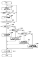
- FIG. 3 is a flowchart illustrating torque calculation processing according to the first embodiment of the present disclosure.
- FIG. 4 is a flowchart illustrating the abnormality determination process according to the first embodiment of the present disclosure.
- FIG. 5 is a flowchart for explaining inter-sensor communication processing according to the first embodiment of the present disclosure.
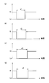
- FIG. 6 is an explanatory diagram illustrating a trigger signal according to the first embodiment of the present disclosure.
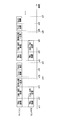
- FIG. 7 is a time chart illustrating signal transmission / reception processing according to the first embodiment of the present disclosure.
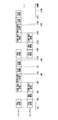
- FIG. 8 is a time chart illustrating signal transmission / reception processing according to the first embodiment of the present disclosure.
- FIG. 9 is a time chart illustrating signal transmission / reception processing according to the first embodiment of the present disclosure.
- FIG. 10 is a flowchart illustrating inter-sensor communication processing according to the second embodiment of the present disclosure.
- FIG. 11 is a time chart illustrating signal transmission / reception processing according to the second embodiment of the present disclosure.
- FIG. 12 is a time chart illustrating signal transmission / reception processing according to the second embodiment of the present disclosure.
- FIGS. 1-10 A first embodiment of the present disclosure is shown in FIGS.
- the sensor device 1 includes a plurality of sensor units 10 and 20 and microcomputers 50 and 60 as a plurality of control units.
- the sensor units 10 and 20 are included in the sensor unit 5, and the microcomputers 50 and 60 are included in the ECU 40.
- FIG. 2 shows an overall configuration of a steering system 90 including the electric power steering device 80.
- a steering wheel 91 as a steering member is connected to a steering shaft 92.
- the steering shaft 92 has an input shaft 921 as a first shaft and an output shaft 922 as a second shaft.
- the input shaft 921 is connected to the steering wheel 91.
- a torque sensor 83 that detects torque applied to the steering shaft 92 is provided between the input shaft 921 and the output shaft 922.
- a pinion gear 96 is provided at the tip of the output shaft 922 opposite to the input shaft 921.
- the pinion gear 96 is engaged with the rack shaft 97.
- a pair of wheels 98 are connected to both ends of the rack shaft 97 via tie rods or the like.
- the steering shaft 92 connected to the steering wheel 91 rotates.
- the rotational motion of the steering shaft 92 is converted into a linear motion of the rack shaft 97 by the pinion gear 96, and the pair of wheels 98 are steered at an angle corresponding to the amount of displacement of the rack shaft 97.
- the electric power steering device 80 includes a motor 81 that outputs an assist torque Ta that assists the steering of the steering wheel 91 by the driver, a reduction gear 82 as a power transmission unit, a torque sensor 83, an ECU 40, and the like.
- the motor 81 and the ECU 40 are separate, but may be integrated.
- the reduction gear 82 reduces the rotation of the motor 81 and transmits it to the steering shaft 92. That is, the electric power steering apparatus 8 of the present embodiment is a so-called “column assist type” in which the driving target is the steering shaft 92, but the driving target is the rack shaft 97 and the rotation of the motor 85 is transmitted to the rack shaft 97. A so-called “rack assist type” may be used.
- the torque sensor 83 is provided on the steering shaft 92 and detects steering torque based on the twist angle between the input shaft 921 and the output shaft 922.
- the torque sensor 83 includes a torsion bar (not shown), a magnetism collecting unit 831 as a detection target, the sensor unit 5 and the like.
- the torsion bar connects the input shaft 921 and the output shaft 922 coaxially on the rotation shaft, and converts the torque applied to the steering shaft 92 into a torsional displacement.
- the magnetic flux collector 831 includes a multipolar magnet, a magnetic yoke, a magnetic flux collecting ring, and the like, and is configured such that the magnetic flux density changes according to the torsional displacement amount and the torsional displacement direction of the torsion bar. Since the general configuration of the torque sensor 83 is well known, detailed illustration of the configuration is omitted.
- the sensor unit 5 includes a first sensor unit 10 and a second sensor unit 20.
- the first sensor unit 10 is provided with a communication terminal 101 and is connected to the first microcomputer 50 via the communication line 31. Thereby, the 1st sensor part 10 and the 1st microcomputer 50 can exchange signals etc.
- the second sensor unit 20 is provided with a communication terminal 201 and is connected to the second microcomputer 60 through the communication line 32. Thereby, the 2nd sensor part 20 and the 2nd microcomputer 60 can exchange signals etc.
- the sensor units 10 and 20 are connected to the ECU 40 by a power line and a ground line (not shown), respectively. Thereby, electric power is supplied to the sensor units 10 and 20 from the ECU 40 side.
- the first sensor unit 10 includes two sensor elements 11 and 12 and a sensor IC 13 as a signal processing unit, and is provided corresponding to the first microcomputer 50.
- the sensor elements 11 and 12 are Hall elements that are magnetic detection elements that detect a change in magnetic flux of the magnetic flux collector 831 according to the torque applied to the steering shaft 92.
- the sensor IC 13 includes A / D conversion units 14 and 15, a calculation unit 16, a communication unit 17, and an inter-sensor communication unit 18.
- the A / D conversion unit 14 converts the detection value of the sensor element 11 into a digital signal
- the A / D conversion unit 15 converts the detection value of the sensor element 12 into a digital signal.
- a signal corresponding to the detection value of the sensor element 11 is referred to as a signal 1A
- a signal corresponding to the detection value of the sensor element 12 is referred to as a signal 1B.
- the calculation unit 16 generates an output signal Sg1 including at least two signals 1A and 1B and signals 2A and 2B described later.
- the communication unit 17 receives the trigger signal transmitted from the first microcomputer 50 and transmits the output signal Sg1 to the first microcomputer 50 according to the received trigger signal.
- the trigger signal is described as “TRG”.
- the inter-sensor communication unit 18 transmits a signal including the signals 1A and 1B to the second sensor unit 20.
- the inter-sensor communication unit 18 receives signals including the signals 2A and 2B transmitted from the second sensor unit 20.
- the received signals 2A and 2B are appropriately used for generating the output signal Sg1.
- the second sensor unit 20 has two sensor elements 21 and 22 and a sensor IC 23 as a signal processing unit, and is provided corresponding to the second microcomputer 60.
- the sensor elements 21 and 22 are Hall elements that are magnetic detection elements that detect a change in magnetic flux of the magnetic flux collector 831 according to the torque applied to the steering shaft 92.
- the sensor IC 23 includes A / D conversion units 24 and 25, a calculation unit 26, a communication unit 27, and an inter-sensor communication unit 28.
- the A / D conversion unit 24 converts the detection value of the sensor element 21 into a digital signal
- the A / D conversion unit 25 converts the detection value of the sensor element 22 into a digital signal.
- a signal corresponding to the detection value of the sensor element 21 is referred to as a signal 2A
- a signal corresponding to the detection value of the sensor element 22 is referred to as a signal 2B.
- the calculation unit 26 generates an output signal Sg2 including at least two of the signals 2A and 2B and the signals 1A and 1B.
- the communication unit 27 receives the trigger signal transmitted from the second microcomputer 60, and transmits the output signal Sg2 to the second microcomputer 60 according to the received trigger signal.
- the inter-sensor communication unit 28 transmits a signal including the signals 2A and 2B to the first sensor unit 10.
- the inter-sensor communication unit 28 receives signals including the signals 1A and 1B transmitted from the first sensor unit 10.
- the received signals 2A and 2B are appropriately used for generating the output signal Sg2.
- inter-sensor communication units 18 and 28 are provided, and signals can be exchanged between the sensor units 10 and 20.
- the signals 1A and 2A are positive signals whose detected values increase as the torque increases, and the signals 1B and 2B are inverted signals whose detected values decrease as the torque increases. That is, in this embodiment, the positive signal is signal A and the inverted signal is signal B. In the present embodiment, the sum of the signal 1A or 2A that is a positive signal and the signal 1B or 2B that is an inverted signal is a predetermined value T if it is normal.
- the ECU 40 is composed mainly of the microcomputers 50 and 60 and performs various arithmetic processes. Each process in the ECU 40 may be a software process by executing a program stored in advance by the CPU, or may be a hardware process by a dedicated electronic circuit.
- the first microcomputer 50 performs various processes based on the output signal Sg1 acquired from the first sensor unit 10.
- the second microcomputer 60 performs various processes based on the output signal Sg2 acquired from the second sensor unit 20.
- the first microcomputer 50 includes a communication unit 51, an abnormality monitoring unit 52, a torque calculation unit 53 as a physical quantity calculation unit, a command calculation unit 55, and the like.
- the communication unit 51 transmits a trigger signal corresponding to the abnormality determination result in the abnormality monitoring unit 52 to the first sensor unit 10, and receives the output signal Sg1 transmitted from the first sensor unit 10 according to the trigger signal.
- the abnormality monitoring unit 52 monitors the abnormality of the sensor elements 11 and 12 based on the output signal Sg1.
- the abnormality of the sensor element 11 is not limited to the abnormality of the sensor element 11 itself, but includes a wiring abnormality, a signal conversion abnormality, and the like. The same applies to the abnormality of the sensor elements 12, 21, and 22.
- the torque calculator 53 calculates the steering torque Ts1 based on the output signal Sg1. Further, the torque calculator 53 calculates the assist torque Ta1 based on the steering torque Ts1.
- the command calculation unit 55 calculates a command value related to driving of the motor 81 based on the assist torque Ta1.
- the second microcomputer 60 includes a communication unit 61, an abnormality monitoring unit 62, a torque calculation unit 63 as a physical quantity calculation unit, a command calculation unit 65, and the like.
- the communication unit 61 transmits a trigger signal corresponding to the abnormality determination result in the abnormality monitoring unit 62 to the second sensor unit 20, and receives the output signal Sg2 transmitted from the second sensor unit 20 according to the trigger signal.
- the abnormality monitoring unit 62 monitors the abnormality of the sensor elements 21 and 22 based on the output signal Sg2.
- the torque calculator 63 calculates the steering torque Ts2 based on the output signal Sg2.
- the torque calculator 63 calculates the assist torque Ta2 based on the steering torque Ts2.
- the command calculation unit 65 calculates a command value related to driving of the motor 81 based on the assist torque Ta2.
- the steering torques Ts1 and Ts2 have the same value if they are normal, but a difference in detection error is allowed.
- a combination of the first sensor unit 10 and the first microcomputer 50 provided correspondingly and a combination of the second sensor unit 20 and the second microcomputer 60 provided correspondingly are referred to as a “system”.
- the combination of the first sensor unit 10 and the first microcomputer 50 will be referred to as “first system”
- the combination of the second sensor unit 20 and the second microcomputer 60 will be referred to as “second system”.
- the 1st sensor part 10 and the 1st microcomputer 50 can communicate directly, and the 1st sensor part 10 and the 2nd microcomputer 60 cannot communicate directly.
- the 2nd sensor part 20 and the 2nd microcomputer 60 can communicate directly, and the 2nd sensor part 20 and the 1st microcomputer 50 cannot communicate directly.
- Digital communication such as SENT (Single Edge Nibble Transmission) communication is performed between the sensor units 10 and 20 and the microcomputers 50 and 60 and between the sensor units 10 and 20, for example.
- the communication method may be other than SENT communication.
- the communication method may be different between communication between the sensor unit and the microcomputer and communication between the sensor units.
- processing in the first system and the processing in the second system are substantially the same, the following description will be mainly given as processing in the first system.
- the torque calculation process will be described based on the flowchart shown in FIG. This processing is executed at predetermined intervals by the microcomputers 50 and 60 during a period in which a start switch such as an ignition switch is turned on. It is assumed that the abnormality determination state immediately after the start switch is turned on is “normal”.
- step S101 step S101
- S step S101
- the communication unit 51 determines whether or not an abnormality determination state described later is stopped. When it is determined that the abnormality determination state is stopped (S101: YES), the processing after S102 is not performed. When it is determined that the abnormality determination state is not stop (S101: NO), the process proceeds to S102.
- the communication unit 51 determines whether or not the abnormality determination state is normal. When it is determined that the abnormality determination state is normal (S102: YES), the process proceeds to S105. When it is determined that the abnormality determination state is not normal (S102: NO), the process proceeds to S103.
- the communication unit 51 determines whether or not the abnormality determination state is A abnormality.
- the “A abnormality” means a state in which an abnormality of the signal A of the own system is specified.
- the first microcomputer 50 is in a state where the abnormality of the signal 1A is specified, and the second microcomputer 60 is in the state where the abnormality of the signal 2A is specified.
- the process proceeds to S106.
- the process proceeds to S104.
- the communication unit 51 determines whether or not the abnormality determination state is B abnormality.
- B abnormality means a state in which an abnormality of the signal 1B is specified.
- the first microcomputer 50 is in a state where the abnormality of the signal 1B is specified, and the second microcomputer 60 is in the state where the abnormality of the signal 2B is specified.
- S104: YES the process proceeds to S107.
- S104: NO the abnormality determination state is abnormality detection, and the process proceeds to S108.
- S101 to S104 are processes for distributing the abnormality determination state, and the processing order can be changed.
- the communication unit 51 transmits a normal trigger TRGc to the first sensor unit 10.
- the communication unit 51 transmits the A abnormality trigger TRGa to the first sensor unit 10.
- the communication unit 51 transmits the B abnormality trigger TRGb to the first sensor unit 10.
- the communication unit 51 transmits the abnormality detection trigger TRGe to the first sensor unit 10.
- FIG. 6 A specific example of the trigger signal is shown in FIG.
- (a) shows the normal trigger TRGc
- (b) shows the A abnormal trigger TRGa
- (c) shows the B abnormal trigger TRGb
- (d) shows the abnormality detection trigger TRGe.
- the normal trigger TRGc, the A abnormal trigger TRGa, the B abnormal trigger TRGb, and the abnormal detection trigger TRGe have a signal level output from the first microcomputer 50 to the first sensor unit 10 from Hi to Lo. It is set according to the switching time.
- the Lo time of the normal trigger TRGc is x1
- the Lo time of the abnormality detection trigger TRGe is x2
- the Lo time of the A abnormality trigger TRGa is x3
- the Lo time of the B abnormality trigger TRGb is x4
- x1 ⁇ x2 ⁇ X3 ⁇ x4 is set.
- the Lo time of each trigger is set to be different by a predetermined tick time (for example, 2 ticks) in units of tick time.
- x1 ⁇ x2 ⁇ x3 ⁇ x4 does not matter.
- Each trigger may be set according to the Hi time instead of the Lo time.
- the trigger signal transmitted from the first microcomputer 50 to the first sensor unit 10 has been described as an example, but the trigger signal transmitted from the second microcomputer 60 to the second sensor unit 20 is the same.
- the communication unit 51 receives the output signal Sg1 transmitted from the first sensor unit 10 in response to the trigger signal.
- the torque calculator 53 calculates the steering torque Ts1 using a normal signal.
- the abnormality determination state is abnormality detection, calculation is performed using a signal before abnormality detection.
- the torque calculator 53 calculates the assist torque Ta based on the steering torque Ts1.
- the abnormality monitoring unit 52 determines whether or not the abnormality determination state is abnormality detection. When it is determined that the abnormality determination state is abnormality detection (S151: YES), the process proceeds to S156. When it is determined that the abnormality determination state is not abnormality detection (S151: NO), the process proceeds to S152.
- the abnormality monitoring unit 52 compares two signals included in the acquired output signal Sg1.
- two signals included in the output signal Sg1 are referred to as “signals C and D”.
- Signals C and D are any of signals 1A, 1B, 2A, and 2B.
- the abnormality determination threshold is Z2 If the signals C and D are both positive signals or inverted signals, and the abnormality determination threshold is Z2, if the absolute value of the difference between the signals C and D is less than or equal to the abnormality determination threshold Z2, the normal determination is made and the abnormality determination threshold Z2 If it is larger, an abnormality is judged. That is, normal determination is made when
- the abnormality monitoring unit 52 determines whether the signals C and D included in the output signal Sg1 are normal. When it is determined that the two signals included in the output signal Sg1 are normal (S153: YES), the process proceeds to S154. When it is determined that the two signals included in the output signal Sg1 are abnormal (S154: NO), the process proceeds to S155.
- the abnormality monitoring unit 52 continues the abnormality determination state. That is, if the signals 1A and 1B are normal, “normal” is continued as the abnormality determination state. If the abnormality of the signal 1A or the signal 1B is specified, “A abnormality” or “B abnormality” is continued as the abnormality determination state.
- the abnormality monitoring unit 52 sets the abnormality determination state to “abnormality detection”.
- the abnormality monitoring unit 52 compares the signal 1A with the signal 2A or the signal 2B, and compares the signal 1B with the signal 1B. An abnormality is identified by comparison with 2A or 2B.
- the signals 1A and 2A are compared, and the signals 1B and 2B are compared. Since the signals 1A and 2A are positive signals and the signals 1B and 2B are inverted signals, the absolute value of the difference between the signals 1A and 2A is larger than the abnormality determination threshold Z3, and the absolute value of the difference between the signals 1B and 2B is abnormal When the threshold value is less than or equal to Z3, the signal 1A is specified as abnormal.
- the signal 1B is specified as abnormal.
- the abnormality determination threshold values Z1, Z2, and Z3 may be the same value or different values.
- the abnormality monitoring unit 52 determines whether or not an abnormal signal has been identified. When it is determined that an abnormal signal has been identified (S157: YES), the process proceeds to S159. When it is determined that an abnormal signal cannot be specified (S157: NO), the process proceeds to S158.
- the abnormality monitoring unit 52 stops the abnormality determination state.
- the abnormality monitoring unit 52 determines whether or not the signal 1A is specified as abnormal. When it is determined that the signal 1A is specified as abnormal (S159: YES), the process proceeds to S160. When it is determined that the signal 1A is not specified as abnormal (S159: NO), that is, when the signal 1B is specified as abnormal, the process proceeds to S161.
- the abnormality monitoring unit 52 sets the abnormality determination state to A abnormality.
- the abnormality monitoring unit 52 sets the abnormality determination state to B abnormality.
- the process of FIG. 5 is a process executed by the sensor ICs 13 and 23 at a predetermined interval.
- the “own system signals A and B” are the signals 1A and 1B
- the “other system signals A and B” are the signals 2A and 2B.
- “Signals A and B” are signals 2A and 2B
- “Other signals A and B” are signals 1A and 1B. Since the processing in the sensor ICs 13 and 23 is substantially the same, here, the processing in the sensor IC 13 will be described.
- the calculation unit 16 acquires the digitally converted signals 1A and 1B of its own system from the A / D conversion units 14 and 15.
- the calculation unit 16 determines whether it is the communication timing between the sensor units. When it is determined that it is not the communication timing (S202: NO), the process returns to S201. When it is determined that the communication timing is reached (S202: YES), the process proceeds to S203.
- the inter-sensor communication unit 18 performs inter-sensor communication with the inter-sensor communication unit 28.
- the inter-sensor communication unit 18 transmits the signals 1A and 1B of its own system to the inter-sensor communication unit 28, and receives the signals 2A and 2B of other systems from the inter-sensor communication unit 28.
- the inter-sensor communication unit 28 transmits the signals 2A and 2B of its own system to the inter-sensor communication unit 18 and receives the signals 1A and 1B of other systems from the inter-sensor communication unit 18.
- the signals 1A, 1B, 2A, and 2B transmitted and received here are digital values after A / D conversion. That is, in this embodiment, signals of other systems are acquired by regular communication at a predetermined cycle regardless of the type of trigger. By adopting regular communication, the control configuration of the sensor ICs 13 and 23 can be simplified.
- the arithmetic unit 16 determines whether or not a trigger signal has been received from the first microcomputer 50. When it is determined that the trigger signal has not been received (S204: NO), the process returns to S201. When it is determined that the trigger signal has been received (S204: YES), the process proceeds to S205.
- the arithmetic unit 16 determines whether or not the received trigger signal is a normal trigger TRGc. When it is determined that the received trigger signal is the normal trigger TRGc (S205: YES), the process proceeds to S208. When it is determined that the received trigger signal is not the normal trigger TRGc (S205: NO), the process proceeds to S206.
- the calculation unit 16 determines whether or not the received trigger signal is the abnormality detection trigger TRGe. When it is determined that the received trigger signal is the abnormality detection trigger TRGe (S206: YES), the process proceeds to S209. When it is determined that the received trigger signal is not the abnormality detection trigger TRGe (S206: NO), the process proceeds to S207.
- the arithmetic unit 16 determines whether or not the received trigger signal is the A abnormality trigger TRGa. When it is determined that the received trigger signal is the A abnormality trigger TRGa (S207: YES), the process proceeds to S210. When it is determined that the received trigger signal is not the A abnormality trigger TRGa (S207: NO), that is, when the received trigger signal is the B abnormality trigger, the process proceeds to S211.
- processing of S205 to S207 is processing for distributing the received trigger signal, and the processing order can be changed. Further, instead of S207, the received trigger signal may be distributed by determining whether or not it is a B abnormality trigger.
- the processing unit 16 When the received trigger signal is determined to be the normal trigger TRGc (S205: YES), the processing unit 16 generates the output signal Sg1 including the signal 1A and the signal 1B of the own system.
- the arithmetic unit 16 receives the signals A and B of its own system and the signals A and B of other systems. An output signal Sg1 is generated.
- the calculation unit 16 when the received trigger signal is determined to be the A abnormality trigger TRGa (S207: YES), the calculation unit 16 generates the output signal Sg1 including the signal 1B of its own system and the signal 2A of the other system. To do.
- the calculation unit 16 when the received trigger signal is a B abnormality trigger (S207: NO), the calculation unit 16 generates the output signal Sg1 including the signal 1A of the own system and the signal 2B of the other system.
- the communication unit 17 transmits the generated output signal Sg1 to the first microcomputer 50.
- the trigger signal is acquired from the second microcomputer 60, and the output signal Sg2 generated according to the trigger signal is output to the second microcomputer 60.
- FIGS. 7 is an example when the abnormality determination state is normal
- FIG. 8 is an example when the abnormality determination state is abnormality detection
- FIG. 9 is an example when the abnormality determination state is A abnormality.
- [p, q] means an output signal including the signal p and the signal q.
- [Own A, Own B] means an output signal including the signal A and the signal B of the own system
- [Own A, Other B] means the signal A of the own system and the signal B of the other system.
- Ts (n) in the figure means that the process is the steering torque Ts1 if the process is in the first system, and the steering torque Ts2 is the process in the second system.
- Ta (n) means assist torque Ta1 if the process is in the first system, and assist torque Ta2 if the process is in the second system. The same applies to FIGS. 11 and 12 described later.
- the first microcomputer 50 transmits a normal trigger TRGc to the sensor IC 13, and the sensor IC 13 receives the normal trigger TRGc.
- the sensor IC 13 receives the normal trigger TRGc, from time x12 to time x13, the sensor IC 13 transmits an output signal including the signals 1A and 1B to the first microcomputer 50, and the first microcomputer 50 outputs an output including the signals 1A and 1B.
- the signal Sg1 is received.
- the first microcomputer 50 receives the output signal Sg1 including the signals 1A and 1B, abnormality determination is performed by comparing the signals 1A and 1B from time x13 to time x14.
- the first microcomputer 50 is based on at least one of the signals 1A and 1B included in the output signal Sg1 acquired from time x12 to time x13 from time x15 to time x16.
- the steering torque Ts1 is calculated, and the assist torque Ta1 is calculated from time x16 to time x17. From time x21 to time x27, processing similar to that at time x11 to time x17 is performed. If the signals 1A and 1B are normal, the same processing is repeated.
- the processing from time x31 to x33 is the same as the processing from time x11 to x13 in FIG. It is assumed that the abnormality is detected when the first microcomputer 50 performs abnormality determination by comparing the signals 1A and 1B from time x33 to time x34. From time x35 to time x36, the steering torque Ts1 is calculated using the signals 1A and 1B before abnormality detection, and the assist torque Ta1 is calculated from time x36 to time x37. When an abnormality is detected, the previous value of the steering torque Ts1 may be taken over instead of the calculation using the signals 1A and 1B before the abnormality is detected. Similarly, the previous value may be taken over for the assist torque Ta.
- the microcomputer 50 transmits an abnormality detection trigger TRGe to the sensor IC 13, and the sensor IC 13 receives the abnormality detection trigger TRGe.
- the sensor IC 13 receives the abnormality detection trigger TRGe
- the sensor IC 13 receives the output signal Sg1 including the signals 1A and 1B and the signals 2A and 2B acquired from the second sensor unit 20 from the time 42 to the time 43. 50.
- the sensor elements 11 and 12 are based on the acquired signals 1A, 1B, 2A, and 2B from time x43 to time x44.
- the first microcomputer 50 calculates the steering torque Ts1 using a normal signal from time x45 to time x46 after the abnormality is specified, and calculates the assist torque Ta1 from time x46 to time x47.
- the first microcomputer 50 Transmits the A abnormality trigger TRGa to the sensor IC 13, and the sensor IC 13 receives the A abnormality trigger TRGa.
- the sensor IC 13 receives the A abnormality trigger, from time x52 to x53, the sensor IC 13 transmits the output signal Sg1 including the signals 2A and 1B to the first microcomputer 50, and the first microcomputer 50 outputs the signals 2A and 1B.
- the signal Sg1 is received.
- the first microcomputer 50 When the first microcomputer 50 receives the output signal Sg1 including the signals 2A and 1B, the first microcomputer 50 performs abnormality determination by comparing the signals 2A and 1B from time x53 to x54. If the signals 2A and 1B are normal, the first microcomputer 50 calculates the steering torque Ts1 based on at least one of the signals 2A and 1B included in the output signal Sg1 acquired from time x52 to time x53. The assist torque Ta1 is calculated from x56 to x57. Similar processing is performed at times x61 to x67. If the signals 2A and 1B are normal, the same processing is repeated.
- the B abnormality trigger TRGb is sent from the first microcomputer 50 instead of the A abnormality trigger TRGa at time x51. It is transmitted to the sensor IC 13. At time x52, the output signal Sg1 including the signals 1A and 2B is transmitted from the sensor IC 13 to the first microcomputer 50.
- the microcomputer 50 compares the signals 1A and 2B, and if normal, calculates the steering torque Ts1 and the assist torque Ta1 using the signals 1A and 2B.
- the signals A and B of the own system become the signals 2A and 2B, and the signals A and B of the other systems become the signals 1A and 1B.
- the details of the processing are the case of the first sensor unit 10 and the first microcomputer 50. It is substantially the same.
- the sensor device 1 of the present embodiment includes a first sensor unit 10 and a first microcomputer 50, and a second sensor unit 20 and a second microcomputer 60, and has a redundant configuration.
- Signals 1A, 1B, 2A, and 2B can be transmitted and received between the sensor units 10 and 20, and the sensor units 10 and 20 send signals to the microcomputers 50 and 60 in response to trigger signals received from the microcomputers 50 and 60. Selected.
- an abnormality occurs in the signal of the own system, it is specified which element is abnormal by using a signal of another system. After the abnormality is specified, a signal from another system is substituted for the signal of the element in which the abnormality has occurred. Thereby, even if an abnormality occurs in some of the sensor elements, the torque calculation in the two systems can be continued while monitoring the abnormality.
- the description is made mainly on the case where the signal 2A is substituted, but the signal 2B is substituted for the signal 1A, and the abnormal signal is transmitted to which of the other systems.
- a signal may be substituted. Even if the signals 1A and 1B are abnormal, if the signals 2A and 2B are normal, the torque calculation can be continued in the second system. Similarly, even if the signals 2A and 2B are abnormal, if the signals 1A and 1B are normal, the torque calculation can be continued in the first system. In other words, in the present embodiment, if two of the four signals are normal, the torque calculation can be continued.
- the sensor device 1 of the present embodiment includes the plurality of sensor units 10 and 20 and the plurality of microcomputers 50 and 60.
- the first sensor unit 10 includes a plurality of sensor elements 11 and 12 and a sensor IC 13.
- the sensor IC 13 generates an output signal Sg1 including a detection signal corresponding to the detection value of the sensor element.
- the second sensor unit 20 includes a plurality of sensor elements and a sensor IC 23.
- the sensor IC 23 generates an output signal Sg2 including a detection signal corresponding to the detection value of the sensor element.
- the first microcomputer 50 includes a communication unit 51, an abnormality monitoring unit 52, and a torque calculation unit 53.
- the communication unit 51 receives the output signal Sg1 transmitted from the corresponding first sensor unit 10 provided.
- the abnormality monitoring unit 52 monitors the abnormality of the first sensor unit 10.
- the torque calculator 53 calculates the steering torque Ts1 based on at least one detection signal that is normal.
- the second microcomputer 60 includes a communication unit 61, an abnormality monitoring unit 62, and a torque calculation unit 63.
- the communication unit 61 receives the output signal Sg2 transmitted from the corresponding second sensor unit 20 provided.
- the abnormality monitoring unit 62 monitors the abnormality of the second sensor unit 20.
- the torque calculator 63 calculates the steering torque Ts2 based on at least one detection signal that is normal.
- “provided correspondingly” means that the first sensor unit 10 and the first microcomputer 50 can communicate with each other, and the second sensor unit 20 and the second microcomputer 60 can communicate with each other. .
- the first sensor unit 10 can transmit and receive detection signals to and from the second sensor unit 20 provided corresponding to the second microcomputer 60 which is another control unit.
- the sensor IC 13 has its own sensor signal (that is, signals 1A and 1B) that is a detection signal acquired in its own first sensor unit 10 and another sensor signal that is a detection signal received from the second sensor unit 20 (that is, An output signal Sg1 including at least two of the signals 2A and 2B) is generated and transmitted to the first microcomputer 50 provided correspondingly.
- the second sensor unit 20 can transmit and receive detection signals to and from the first sensor unit 10 provided corresponding to the first microcomputer 50 which is another control unit.
- the sensor IC 23 has its own sensor signal (that is, signals 2A and 2B) that is a detection signal acquired within its second sensor unit 20, and another sensor signal that is a detection signal received from the first sensor unit 10 (that is, The output signal Sg2 including at least two of the signals 1A and 2B) is generated and transmitted to the second microcomputer 60 provided correspondingly.
- the torque calculation unit 53 performs torque calculation using at least one normal signal among the detection signals included in the output signal Sg1.
- the signal used for the torque calculation may be a self sensor signal or another sensor signal. The same applies to the torque calculation in the torque calculation unit 63.
- the first microcomputer 50 receives the second signals in addition to the signals 1A and 1B of the first sensor unit 10 provided correspondingly.
- the signals 2A and 2B of the sensor unit 20 can be acquired.
- the 2nd microcomputer 60 can acquire signals 1A and 1B of the 1st sensor part 10 in addition to signals 2A and 2B of the 2nd sensor part 20 provided correspondingly. That is, the microcomputers 50 and 60 can appropriately use the four signals 1A, 1B, 2A, and 2B.
- the first sensor unit 10 can receive a trigger signal from the corresponding first microcomputer 50, and selects signals 1A, 1B, 2A, and 2B to be included in the output signal Sg1 according to the received trigger signal.
- the 2nd sensor part 20 can receive a trigger signal from the 2nd microcomputer 60 provided correspondingly, and chooses signal 1A, 1B, 2A, and 2B included in output signal Sg2 according to the received trigger signal.
- the signals 1A, 1B, 2A, and 2B included in the output signals Sg1 and Sg2 can be appropriately selected. Further, by selecting a necessary signal according to the trigger signal, it is possible to shorten the communication time as compared with the case where all the signals 1A, 1B, 2A, and 2B are always included in the output signals Sg1 and Sg2.
- the first sensor unit 10 receives the signals 2A and 2B from the second sensor unit 20 at a predetermined cycle.
- the second sensor unit 20 receives the signals 1A and 1B from the first sensor unit at a predetermined cycle.
- the control configuration in the sensor units 10 and 20 can be simplified by making the communication between the sensor units 10 and 20 regular communication in a predetermined cycle.
- the abnormality monitoring unit 52 detects abnormality of the sensor elements 11 and 12 based on the signals 1A and 1B which are a plurality of own sensor signals.
- the abnormality monitoring unit 62 detects abnormality of the sensor elements 21 and 22 based on the signals 2A and 2B which are a plurality of own sensor signals.
- the abnormality monitoring unit 52 detects abnormality of the sensor elements 11 and 12 based on the signals 1A and 1B
- the abnormality monitoring unit 52 identifies the abnormal sensor elements 11 and 12 using the signals 1A and 1B and at least one signal 2A and 2B.
- the abnormality monitoring unit 62 detects abnormality of the sensor elements 21 and 22 based on the signals 2A and 2B
- the abnormality monitoring unit 62 identifies the abnormal sensor elements 11 and 12 using the signals 2A and 2B and at least one signal 1A and 1B. To do.
- the abnormality monitoring units 52 and 62 continue to monitor the abnormality with at least two signals that are normal among the signals 1A, 1B, 2A, and 2B. Thereby, if at least two signals are normal among the own sensor signal and the other sensor signal, the abnormality monitoring by the signal comparison can be continued. Further, the torque calculation units 53 and 63 can appropriately continue the torque calculation using a normal signal.
- Sensor elements 11, 12, 21, and 22 are magnetic detection elements that detect a magnetic flux to be detected.
- the sensor elements 11, 12, 21, and 22 detect changes in magnetic flux that change according to torque.
- the torque calculators 53 and 63 calculate torque as a physical quantity.
- the sensor device 1 of the present embodiment is a torque sensor, and can appropriately detect torque (steering torques Ts1, Ts2 in the present embodiment).
- the electric power steering device 8 includes the sensor device 1, a motor 81 that outputs an assist torque Ta that assists the driver in steering the steering wheel 91, and a reduction gear 82 that transmits the torque of the motor 81 to the steering shaft 92. Prepare.
- the torque calculators 53 and 63 calculate steering torques Ts1 and Ts2 as physical quantities.
- the first microcomputer 50 includes a command calculation unit 45 that calculates a command value related to drive control of the motor 81 based on the steering torque Ts1.
- the second microcomputer 60 includes a command calculation unit 45 that calculates a command value related to drive control of the motor 81 based on the steering torque Ts2.
- the steering torques Ts1 and Ts2 are appropriately calculated.
- the assist torque Ta is appropriately calculated based on the steering torques Ts1 and Ts2, and the driving of the motor 81 can be appropriately controlled.
- the communication units 51 and 61 of the microcomputers 50 and 60 correspond to “communication units”.
- the signals 1A, 1B, 2A, and 2B correspond to “detection signals”.
- the signals 1A and 1B correspond to the “own sensor signal” and the signals 2A and 2B correspond to the “other sensor signal”.
- the signals 2A and 2B correspond to the “self sensor signal” and the signals 1A and 1B. Corresponds to the “other sensor signal”.
- FIGS. 1-10 A second embodiment of the present disclosure is shown in FIGS.
- signals of other systems are acquired at a predetermined cycle regardless of the type of trigger, whereas in this embodiment, signals of other systems are acquired according to the type of trigger signal.
- the point is different. Since the configuration of the sensor unit 5 and the ECU 40 are the same as those in the above embodiment, the description thereof is omitted.
- the processing in the microcomputers 50 and 60 is substantially the same as that in the above embodiment.
- processing in the first system and the processing in the second system are substantially the same, the following description is mainly given as processing in the first system.
- the processing of S301 is the same as the processing of S201 in FIG. 5, and the processing of S302 to S306 is the same as the processing of S204 to S208.
- the received trigger signal is a normal trigger (S303: YES)
- the output signal Sg1 including the signals 1A and 1B of the own system is obtained in S306 without acquiring the signals 2A and 2B of other systems. Generate.
- the inter-sensor communication unit 18 receives the signals 2A and 2B of other systems.
- the other-system signals 2A and 2B received here are digital values after A / D conversion, as in S203.
- signals acquired in the steps described later are digital values after A / D conversion.
- the calculation unit 16 generates an output signal Sg1 including the signals 1A and 1B of its own system and the signals 2A and 2B of other systems.
- the inter-sensor communication unit 18 receives the signal 2A of another system.
- the calculation part 16 produces
- the inter-sensor communication unit 18 When it is determined that the received trigger signal is not the A abnormality trigger TRGa (S305: NO), that is, when the received trigger signal is the B abnormality trigger TRGb, in S311, the inter-sensor communication unit 18 is connected to another system. The signal 2B is received.
- the arithmetic unit 16 generates the output signal Sg1 including the signal 1B of its own system and the signal 2A of the other system, similar to S211.
- S313 that moves to S306, S308, S310, or S312 is the same as S212.
- FIG. 11 shows an example when the abnormality determination state is abnormality detection
- FIG. 12 shows an example when the abnormality determination state is A abnormality. Note that the chart when the abnormality determination state is normal is the same as that of the first embodiment, and a description thereof will be omitted.
- the processing at times x71 to x77 in FIG. 11 is the same as the processing at times x31 to x37 in FIG.
- the microcomputer 50 transmits the abnormality detection trigger TRGe to the sensor IC 13, and the sensor IC 13 receives the abnormality detection trigger TRGe.
- the sensor IC 13 Upon receiving the abnormality detection trigger TRGe, the sensor IC 13 receives the signals 2A and 2B from the second sensor unit 20 from time x82 to time x83.
- the processing from time x83 to x88 is the same as the processing from time x42 to time x47 in FIG.
- the signal A of the own system (here, the signal 1A) is specified to be abnormal and the abnormality determination state is A abnormality, as shown in FIG. 12, from the time x91 to the time x92, the microcomputer 50
- the A abnormality trigger TRGa is transmitted to the sensor IC 13, and the sensor IC 13 receives the A abnormality trigger TRGa.
- the sensor IC 13 receives the signal 2A from the second sensor unit 20 from time x92 to time x93.
- the processing at times x93 to x98 is the same as the processing at times x52 to x57 in FIG.
- the processing at times x101 to x108 is the same as the processing at times x91 to x98. If the signals 2A and 1B are normal, the same processing is repeated.
- the B abnormality trigger TRGb is sent from the microcomputer 50 to the sensor IC 13 instead of the A abnormality trigger TRGa. Sent to. At time x92, the sensor IC 13 receives the signal 2B from the second sensor unit 20. At time x93, an output signal including signals 1A and 2B is transmitted from the sensor IC 13 to the microcomputer 50.
- the signals A and B of the own system become the signals 2A and 2B, and the signals A and B of the other system become the signals 1A and 1B.
- the second sensor unit 20 receives signals 1A and 1B if the received trigger signal is an abnormality detection trigger TRGe, signals 1A if the trigger signal is A abnormal trigger TRGa, and signals 1B if the trigger signal is B abnormal trigger TRGb. 10 from.
- the details of the other processes are substantially the same as those of the first sensor unit 10 and the first microcomputer 50.
- the sensor units 10 and 20 receive signals from other systems when the received trigger signal is the abnormality detection trigger TRGe, the A abnormality trigger TRGa, or the B abnormality trigger TRGb.
- the received trigger signal is the abnormality detection trigger TRGe, the A abnormality trigger TRGa, or the B abnormality trigger TRGb.
- the sensor element is normal and the received trigger signal is the normal trigger TRGc, no signal is received from another system. That is, in this embodiment, signals of other systems are acquired by event communication according to the type of trigger. Thereby, the communication load between the sensor units 10 and 20 at the normal time can be reduced.
- the first sensor unit 10 receives the signals 2A and 2B from the second sensor unit 20 in response to the trigger signal.
- the second sensor unit 20 receives the signals 1A and 1B from the first sensor unit 10 in response to the trigger signal.
- the communication load during normal operation can be reduced.
- one of the detection signals of the two sensor elements provided in one sensor unit is a positive signal and the other is an inverted signal.
- the detection signals of the plurality of sensor elements may have the same value if normal. That is, the plurality of detection signals may be positive signals or inverted signals.
- the sensor unit receives the other sensor signal in the signal cycle in which the abnormality detection trigger is received, and transmits the output signal including the own sensor signal and the other sensor signal to the corresponding control unit.
- the sensor unit transmits an output signal that includes the self-sensor signal and does not include the other sensor signal to the control unit in the signal cycle in which the abnormality detection trigger is first received. Then, the other sensor signal is acquired from the other system sensor unit until the signal transmission of the next cycle, and the output signal including the own sensor signal and the other sensor signal is transmitted to the control unit in the signal cycle after the next time. It may be. Thereby, communication delay can be prevented.
- the signal cycle in which the abnormality detection trigger is first received includes the self sensor signal and does not include the other sensor signal.
- the output signal including the own sensor signal and the other sensor signal may be transmitted to the control unit in the signal cycle after the next time.
- a signal acquired from another system may be any signal of another system.
- the signal 2B may be acquired instead of the signal 2A.
- (D) Sensor device The sensor device of the above embodiment is provided with two sets of sensor units and a control unit. In other embodiments, three or more sets of sensor units and control units may be provided. Moreover, in the said embodiment, one sensor part is provided with respect to one control part. In another embodiment, a plurality of sensor units may be provided for one control unit.
- the communication between the sensor unit and the control unit is so-called “synchronous communication” in which an output signal is transmitted from the sensor unit in response to a trigger signal from the control unit.
- the sensor unit receives all other sensor signals by regular communication, and the output signal includes all of the own sensor signal and other sensor signals, the trigger from the control unit It is good also as what is called “asynchronous communication” in which an output signal is output from a sensor part irrespective of a signal.
- each sensor unit has two sensor elements.
- each sensor unit may be provided with three or more sensor elements.
- the abnormality is identified by comparing the self-sensor signals, and abnormality is detected when there are two self-sensor signals that can be used for abnormality monitoring.
- abnormality identification using other sensor signals may be performed. Even when three or more own sensor signals are available for abnormality monitoring, abnormality identification using other sensor signals may be performed.
- the sensor element is a magnetic detection element.
- the sensor element may be an element that detects a physical quantity other than the magnetic flux.
- the sensor element of the said embodiment detects steering torque.
- the sensor element may detect any physical quantity such as torque other than steering torque, rotation angle, stroke, load, pressure, and the like.
- the sensor device is applied to a torque sensor of an electric power steering device.
- the sensor device may be applied to a vehicle-mounted device other than the electric power steering device, or may be applied to a device that is not mounted on a vehicle.
- each section is expressed as S101, for example.
- each section can be divided into a plurality of subsections, while a plurality of sections can be combined into one section.
- each section configured in this manner can be referred to as a device, module, or means.
Landscapes
- Physics & Mathematics (AREA)
- General Physics & Mathematics (AREA)
- Engineering & Computer Science (AREA)
- Chemical & Material Sciences (AREA)
- Combustion & Propulsion (AREA)
- Transportation (AREA)
- Mechanical Engineering (AREA)
- Power Steering Mechanism (AREA)
- Steering Control In Accordance With Driving Conditions (AREA)
- Transmission And Conversion Of Sensor Element Output (AREA)
Abstract
センサ装置は、複数のセンサ素子(11、12、21、22)、および、前記センサ素子の検出値に応じた検出信号を含む出力信号を生成する信号処理部(13、23)を有する複数のセンサ部(10、20)と、前記出力信号を受信する通信部(51、61)、前記センサ部の異常を監視する異常監視部(52、62)、および、正常である少なくとも1つの前記検出信号に基づいて物理量を演算する物理量演算部(53、63)を有する複数の制御部(50、60)とを備える。前記センサ部は、他の前記制御部に対応する他系統センサ部と、前記検出信号を相互に送受信可能である。前記信号処理部は、自身の前記センサ部内にて取得した自センサ信号、および、前記他系統センサ部から受信した他センサ信号のうち少なくとも2つが含まれる前記出力信号を生成し、前記制御部に送信する。
Description
本出願は、2016年3月17日に出願された日本特許出願番号2016-53614号に基づくもので、ここにその記載内容を援用する。
本開示は、センサ装置、および、これを用いた電動パワーステアリング装置に関するものである。
従来、2系統のトルクセンサを有する電動パワーステアリング装置が知られている。例えば特許文献1では、一方のトルクセンサの異常が検出された場合には、異常が検出されていない側のトルクセンサにより検出される操舵トルクを使って操舵アシスト制御を継続している。
特許文献1では、トルクセンサの検出値と推定トルクとの偏差に基づき、異常が生じているトルクセンサを特定する。また、トルクセンサの検出値と推定トルクとの偏差に基づいて目標アシストトルクの上限値を設定することで、過剰アシストを防止している。
しかしながら、特許文献1では、一方のトルクセンサの異常が検出された場合、両方のトルクセンサの検出値の比較による異常検出を行うことができず、異常検出精度が低下する虞がある。
本開示は、一部のセンサ素子に異常が生じた場合であっても異常監視および物理量演算を継続可能なセンサ装置、および、これを用いた電動パワーステアリング装置を提供することを目的とする。
本開示の第一の態様において、センサ装置は、複数のセンサ素子、および、前記センサ素子の検出値に応じた検出信号を含む出力信号を生成する信号処理部を有する複数のセンサ部と、対応して設けられる前記センサ部から送信される前記出力信号を受信する通信部、前記センサ部の異常を監視する異常監視部、および、正常である少なくとも1つの前記検出信号に基づいて物理量を演算する物理量演算部を有する複数の制御部とを備える。前記センサ部は、他の前記制御部に対応して設けられる前記センサ部である他系統センサ部と、前記検出信号を相互に送受信可能である。前記信号処理部は、自身の前記センサ部内にて取得した前記検出信号である自センサ信号、および、前記他系統センサ部から受信した前記検出信号である他センサ信号のうち少なくとも2つが含まれる前記出力信号を生成し、対応して設けられる前記制御部に送信する。
上記のセンサ装置において、一部のセンサ素子に異常が生じた場合であっても、2つ以上のセンサ素子が正常であれば、信号比較による異常監視、および、トルク演算を継続可能である。
本開示の第二の態様において、電動パワーステアリング装置は、第一の態様のセンサ装置と、運転者による操舵部材の操舵を補助するアシストトルクを出力するモータと、前記モータのトルクを駆動対象に伝達する動力伝達部とを備える。前記物理量演算部は、前記物理量として操舵トルクを演算する。前記制御部は、前記操舵トルクに基づいて前記モータの駆動制御に係る指令値を演算する指令演算部を有する。
上記の電動パワーステアリング装置において、一部のセンサ素子に異常が生じた場合であっても、2つ以上のセンサ素子が正常であれば、信号比較による異常監視、および、トルク演算を継続可能である。
本開示についての上記目的およびその他の目的、特徴や利点は、添付の図面を参照しながら下記の詳細な記述により、より明確になる。その図面は、
図1は、本開示の第1実施形態によるセンサ装置の構成を示すブロック図であり、
図2は、本開示の第1実施形態によるステアリングシステムの概略構成図であり、
図3は、本開示の第1実施形態によるトルク演算処理を説明するフローチャートであり、
図4は、本開示の第1実施形態による異常判定処理を説明するフローチャートであり、
図5は、本開示の第1実施形態によるセンサ間通信処理を説明するフローチャートであり、
図6は、本開示の第1実施形態によるトリガ信号を説明する説明図であり、
図7は、本開示の第1実施形態による信号送受信処理を説明するタイムチャートであり、
図8は、本開示の第1実施形態による信号送受信処理を説明するタイムチャートであり、
図9は、本開示の第1実施形態による信号送受信処理を説明するタイムチャートであり、
図10は、本開示の第2実施形態によるセンサ間通信処理を説明するフローチャートであり、
図11は、本開示の第2実施形態による信号送受信処理を説明するタイムチャートであり、
図12は、本開示の第2実施形態による信号送受信処理を説明するタイムチャートである。
以下、本開示によるセンサ装置、および、これを用いた電動パワーステアリング装置を図面に基づいて説明する。なお、以下、複数の実施形態において、実質的に同一の構成には同一の符号を付して説明を省略する。
(第1実施形態)
本開示の第1実施形態を図1~図9に示す。
本開示の第1実施形態を図1~図9に示す。
図1に示すように、センサ装置1は、複数のセンサ部10、20と、複数の制御部としてのマイコン50、60を備える。センサ部10、20はセンサユニット5に含まれ、マイコン50、60はECU40に含まれる。
図2に示すように、センサユニット5およびECU40は、例えば車両のステアリング操作を補助するための電動パワーステアリング装置80に適用される。図2は、電動パワーステアリング装置80を備えるステアリングシステム90の全体構成を示すものである。
図2に示すように、操舵部材としてのステアリングホイール91は、ステアリングシャフト92と接続される。ステアリングシャフト92は、第1の軸としての入力軸921および第2の軸としての出力軸922を有する。入力軸921は、ステアリングホイール91と接続される。入力軸921と出力軸922との間には、ステアリングシャフト92に加わるトルクを検出するトルクセンサ83が設けられる。出力軸922の入力軸921と反対側の先端には、ピニオンギア96が設けられる。ピニオンギア96はラック軸97に噛み合っている。ラック軸97の両端には、タイロッド等を介して一対の車輪98が連結される。
運転者がステアリングホイール91を回転させると、ステアリングホイール91に接続されたステアリングシャフト92が回転する。ステアリングシャフト92の回転運動は、ピニオンギア96によってラック軸97の直線運動に変換され、ラック軸97の変位量に応じた角度に一対の車輪98が操舵される。
電動パワーステアリング装置80は、運転者によるステアリングホイール91の操舵を補助するアシストトルクTaを出力するモータ81、動力伝達部としての減速ギア82、トルクセンサ83、および、ECU40等を備える。図2では、モータ81とECU40とが別体となっているが、一体としてもよい。
減速ギア82は、モータ81の回転を減速してステアリングシャフト92に伝える。すなわち、本実施形態の電動パワーステアリング装置8は、駆動対象がステアリングシャフト92である、所謂「コラムアシストタイプ」であるが、駆動対象をラック軸97とし、モータ85の回転をラック軸97に伝える所謂「ラックアシストタイプ」としてもよい。
トルクセンサ83は、ステアリングシャフト92に設けられ、入力軸921と出力軸922との捩れ角に基づき、操舵トルクを検出する。トルクセンサ83は、図示しないトーションバー、検出対象としての集磁部831、および、センサユニット5等を有する。トーションバーは、入力軸921と出力軸922とを回転軸上にて同軸に連結し、ステアリングシャフト92に加わるトルクを捩れ変位に変換する。集磁部831は、多極磁石、磁気ヨーク、および、集磁リング等を有し、トーションバーの捩れ変位量および捩れ変位方向に応じて、磁束密度が変化するように構成される。トルクセンサ83の一般的な構成は周知であるため、構成詳細の図示を省略する。
図1に示すように、センサユニット5は、第1センサ部10、および、第2センサ部20を有する。
第1センサ部10には、通信端子101が設けられ、通信線31にて第1マイコン50と接続される。これにより、第1センサ部10と第1マイコン50とは、信号等を授受可能である。第2センサ部20には、通信端子201が設けられ、通信線32にて第2マイコン60と接続される。これにより、第2センサ部20と第2マイコン60とは、信号等を授受可能である。
また、センサ部10、20は、それぞれ図示しない電源線およびグランド線により、ECU40と接続される。これにより、センサ部10、20には、ECU40側から給電される。
第1センサ部10は、2つのセンサ素子11、12、および、信号処理部としてのセンサIC13を有し、第1マイコン50に対応して設けられる。センサ素子11、12は、ステアリングシャフト92に加わるトルクに応じた集磁部831の磁束の変化を検出する磁気検出素子であるホール素子とする。
センサIC13は、A/D変換部14、15、演算部16、通信部17、および、センサ間通信部18を有する。
A/D変換部14は、センサ素子11の検出値をデジタル信号に変換し、A/D変換部15は、センサ素子12の検出値をデジタル信号に変換する。以下、センサ素子11の検出値に応じた信号を信号1A、センサ素子12の検出値に応じた信号を信号1Bとする。
演算部16は、信号1A、1B、および、後述する信号2A、2Bの少なくとも2つを含む出力信号Sg1を生成する。
通信部17は、第1マイコン50から送信されるトリガ信号を受信し、受信したトリガ信号に応じ、出力信号Sg1を第1マイコン50に送信する。図1中では、トリガ信号を「TRG」と記載する。
センサ間通信部18は、信号1A、1Bを含む信号を第2センサ部20に送信する。また、センサ間通信部18は、第2センサ部20から送信される信号2A、2Bを含む信号を受信する。受信した信号2A、2Bは、適宜、出力信号Sg1の生成に用いられる。
第2センサ部20は、2つのセンサ素子21、22、および、信号処理部としてのセンサIC23を有し、第2マイコン60に対応して設けられる。センサ素子21、22は、センサ素子11、12と同様、ステアリングシャフト92に加わるトルクに応じた集磁部831の磁束の変化を検出する磁気検出素子であるホール素子とする。
センサIC23は、A/D変換部24、25、演算部26、通信部27、および、センサ間通信部28を有する。
A/D変換部24は、センサ素子21の検出値をデジタル信号に変換し、A/D変換部25は、センサ素子22の検出値をデジタル信号に変換する。以下、センサ素子21の検出値に応じた信号を信号2A、センサ素子22の検出値に応じた信号を信号2Bとする。
演算部26は、信号2A、2B、および、信号1A、1Bの少なくとも2つを含む出力信号Sg2を生成する。
通信部27は、第2マイコン60から送信されるトリガ信号を受信し、受信したトリガ信号に応じ、出力信号Sg2を第2マイコン60に送信する。
センサ間通信部28は、信号2A、2Bを含む信号を第1センサ部10に送信する。また、センサ間通信部28は、第1センサ部10から送信される信号1A、1Bを含む信号を受信する。受信した信号2A、2Bは、適宜、出力信号Sg2の生成に用いられる。
本実施形態では、センサ間通信部18、28が設けられており、センサ部10、20間にて信号を授受可能である。
信号1A、2Aは、トルクが大きくなるに従って検出値が大きくなる正信号であり、信号1B、2Bは、トルクが大きくなるに従って検出値が小さくなる反転信号である。すなわち本実施形態では、正信号を信号A、反転信号を信号Bとする。本実施形態では、正信号である信号1Aまたは信号2Aと、反転信号である信号1Bまたは信号2Bとの和は、正常であれば所定値Tとなる。
ECU40は、マイコン50、60等を主体として構成され、各種演算処理を行う。ECU40における各処理は、予め記憶されたプログラムをCPUで実行することによるソフトウェア処理であってもよいし、専用の電子回路によるハードウェア処理であってもよい。第1マイコン50は、第1センサ部10から取得される出力信号Sg1に基づき、各種処理を行う。第2マイコン60は、第2センサ部20から取得される出力信号Sg2に基づき、各種処理を行う。
第1マイコン50は、通信部51、異常監視部52、物理量演算部としてのトルク演算部53、および、指令演算部55等を有する。
通信部51は、異常監視部52における異常判定結果に応じたトリガ信号を第1センサ部10に送信し、トリガ信号に応じて第1センサ部10から送信される出力信号Sg1を受信する。
異常監視部52は、出力信号Sg1に基づき、センサ素子11、12の異常を監視する。なお、センサ素子11の異常には、センサ素子11そのものの異常に限らず、配線異常や信号変換異常等が含まれるが、適宜、単にセンサ素子11の異常と記載する。センサ素子12、21、22の異常についても同様である。
トルク演算部53は、出力信号Sg1に基づき、操舵トルクTs1を演算する。また、トルク演算部53は、操舵トルクTs1に基づき、アシストトルクTa1を演算する。
指令演算部55は、アシストトルクTa1に基づき、モータ81の駆動に係る指令値を演算する。
第2マイコン60は、通信部61、異常監視部62、物理量演算部としてのトルク演算部63、および、指令演算部65等を有する。
通信部61は、異常監視部62における異常判定結果に応じたトリガ信号を第2センサ部20に送信し、トリガ信号に応じて第2センサ部20から送信される出力信号Sg2を受信する。
異常監視部62は、出力信号Sg2に基づき、センサ素子21、22の異常を監視する。
トルク演算部63は、出力信号Sg2に基づき、操舵トルクTs2を演算する。また、トルク演算部63は、操舵トルクTs2に基づき、アシストトルクTa2を演算する。
指令演算部65は、アシストトルクTa2に基づき、モータ81の駆動に係る指令値を演算する。
本実施形態では、操舵トルクTs1、Ts2は、正常であれば同じ値となるが、検出誤差程度の差は許容される。また、アシストトルクTa1、Ta2は、モータ81として出力すべきアシストトルクTaの1/2とする。すなわち、Ta=Ta1+Ta2である。
ここで、対応して設けられる第1センサ部10と第1マイコン50との組み合わせ、および、対応して設けられる第2センサ部20と第2マイコン60との組み合わせを、「系統」とする。以下適宜、第1センサ部10と第1マイコン50との組み合わせを「第1系統」、第2センサ部20と第2マイコン60との組み合わせを「第2系統」とする。本実施形態では、第1センサ部10と第1マイコン50とは直接的に通信可能であり、第1センサ部10と第2マイコン60とは直接的には通信不能である。また、第2センサ部20と第2マイコン60とは直接的に通信可能であり、第2センサ部20と第1マイコン50とは直接的には通信不能である。
センサ部10、20とマイコン50、60との間、および、センサ部10、20間では、例えばSENT(Single Edge Nibble Transmission)通信等のデジタル通信が行われる。通信方法は、SENT通信以外であってもよい。また、センサ部とマイコンとの間での通信と、センサ部間での通信とで、通信方式が異なっていてもよい。
第1系統での処理と第2系統での処理とは、略同様であるので、以下、主に第1系統での処理として説明する。
図3に示すフローチャートに基づき、トルク演算処理を説明する。この処理は、イグニッションスイッチ等である始動スイッチがオンされている期間に、マイコン50、60にて所定の間隔で実行される。なお、始動スイッチがオンされた直後の異常判定状態は、「正常」であるものとする。
以下、例えば「ステップS101」の「ステップ」を省略し、単に記号「S」と記す。S101以外のステップも同様である。
最初のS101では、通信部51は、後述する異常判定状態が停止か否かを判断する。異常判定状態が停止であると判断された場合(S101:YES)、S102以降の処理を行わない。異常判定状態が停止ではないと判断された場合(S101:NO)、S102へ移行する。
S102では、通信部51は、異常判定状態が正常か否かを判断する。異常判定状態が正常であると判断された場合(S102:YES)、S105へ移行する。異常判定状態が正常ではないと判断された場合(S102:NO)、S103へ移行する。
S103では、通信部51は、異常判定状態がA異常か否かを判断する。「A異常」とは、自系統の信号Aの異常が特定されている状態を意味するものである。第1マイコン50では信号1Aの異常が特定されている状態であり、第2マイコン60では信号2Aの異常が特定されている状態である。異常判定状態がA異常であると判断された場合(S103:YES)、S106へ移行する。異常判定状態がA異常ではないと判断された場合(S103:NO)、S104へ移行する。
S104では、通信部51は、異常判定状態がB異常か否かを判断する。「B異常」とは、信号1Bの異常が特定されている状態を意味する。第1マイコン50では信号1Bの異常が特定されている状態であり、第2マイコン60では信号2Bの異常が特定されている状態である。異常判定状態がB異常であると判断された場合(S104:YES)、S107へ移行する。異常判定状態がB異常ではないと判断された場合(S104:NO)、異常判定状態は異常検出であって、S108へ移行する。
なお、S101~S104は、異常判定状態を振り分けるための処理であり、処理順は入れ替え可能である。
異常判定状態が正常であると判断された場合(S102:YES)に移行するS105では、通信部51は、正常トリガTRGcを第1センサ部10に送信する。
異常判定状態がA異常であると判断された場合(S103:YES)に移行するS106では、通信部51は、A異常トリガTRGaを第1センサ部10に送信する。
異常判定状態がB異常であると判断された場合(S104:YES)に移行するS107では、通信部51は、B異常トリガTRGbを第1センサ部10に送信する。
異常判定状態が異常検出である場合(S104:NO)に移行するS108では、通信部51は、異常検出トリガTRGeを第1センサ部10に送信する。
トリガ信号の具体例を図6に示す。図6では、(a)が正常トリガTRGc、(b)がA異常トリガTRGa、(c)がB異常トリガTRGb、(d)が異常検出トリガTRGeを示す。図6に示す例では、正常トリガTRGc、A異常トリガTRGa、B異常トリガTRGb、および、異常検出トリガTRGeは、第1マイコン50から第1センサ部10に出力される信号レベルがHiからLoに切り替えられる時間に応じて設定される。本実施形態では、正常トリガTRGcのLo時間がx1、異常検出トリガTRGeのLo時間がx2、A異常トリガTRGaのLo時間がx3、B異常トリガTRGbのLo時間がx4であって、x1<x2<x3<x4となるように設定されている。各トリガのLo時間は、チックタイム単位で、所定のチックタイム(例えば2tick)分、異なるように設定される。ここでは、x1<x2<x3<x4としたが、x1~x4の大小順は問わない。また、各トリガは、Lo時間に替えて、Hi時間に応じて設定してもよい。ここでは、第1マイコン50から第1センサ部10に送信されるトリガ信号を例に説明したが、第2マイコン60から第2センサ部20に送信されるトリガ信号も同様である。
図3に戻り、S105~S108に続いて移行するS109では、通信部51は、トリガ信号に応じて第1センサ部10から送信される出力信号Sg1を受信する。
S109に続いて移行するS110では、異常判定処理を行う。ここでは、S109に続いて異常判定処理を行うものとして説明するが、例えばカウンタ等を用いて所定の頻度で異常判定処理を行ってもよい。また、図4に示す異常判定処理は、トルク演算処理とは別途に行われるようにしてもよい。
異常判定処理に続いて移行するS111では、トルク演算部53は、正常である信号を用い、操舵トルクTs1を演算する。なお、異常判定状態が異常検出である場合、異常検出前の信号を用いて演算する。
S112では、トルク演算部53は、操舵トルクTs1に基づき、アシストトルクTaを演算する。
図4に示すフローチャートに基づいて異常判定処理を説明する。
S151では、異常監視部52は、異常判定状態が異常検出か否かを判断する。異常判定状態が異常検出であると判断された場合(S151:YES)、S156へ移行する。異常判定状態が異常検出ではないと判断された場合(S151:NO)、S152へ移行する。
S152では、異常監視部52は、取得した出力信号Sg1に含まれる2信号を比較する。ここで、出力信号Sg1に含まれる2信号を、「信号C、D」とする。信号C、Dは、信号1A、1B、2A、2Bのいずれかである。
信号C、Dの一方が正信号、他方が反転信号である場合、正常である場合の信号C、Dの和をT、異常判定閾値をZ1とすると、信号C、Dの和がT-Z1以上、T+Z1以下の場合、正常判定し、T-Z1未満、または、T+Z1より大きい場合、異常判定する。すなわち、(T-Z1)≦(C+D)≦(T+Z1)で正常判定し、(C+D)<(T-Z1)または(T+Z1)<(C+D)で異常判定する。
信号C、Dがともに正信号または反転信号である場合、異常判定閾値をZ2とすると、信号C、Dの差の絶対値が異常判定閾値Z2以下の場合、正常判定し、異常判定閾値Z2より大きい場合、異常判定する。すなわち、|C-D|≦Z2で正常判定し、|C-D|>Z2で異常判定する。
2つの信号の和や差等の演算値と判定閾値との比較を行うことは、「信号を比較する」という概念に含まれるものとする。
S153では、異常監視部52は、出力信号Sg1に含まれる信号C、Dが正常か否かを判断する。出力信号Sg1に含まれる2信号が正常であると判断された場合(S153:YES)、S154へ移行する。出力信号Sg1に含まれる2信号が異常であると判断された場合(S154:NO)、S155へ移行する。
S154では、異常監視部52は、異常判定状態を継続する。すなわち、信号1A、1Bが正常であれば、異常判定状態として「正常」を継続する。また、信号1Aまたは信号1Bの異常が特定されていれば、異常判定状態として「A異常」または「B異常」を継続する。
S155では、異常監視部52は、異常判定状態を「異常検出」とする。
異常判定状態が異常検出であると判断された場合(S151:YES)に移行するS156では、異常監視部52は、信号1Aと、信号2Aまたは信号2Bとの比較、および、信号1Bと、信号2Aまたは信号2Bとの比較により、異常特定を行う。本実施形態では、信号1A、2Aを比較し、信号1B、2Bを比較する。信号1A、2Aが正信号、信号1B、2Bが反転信号であるので、信号1A、2Aの差の絶対値が異常判定閾値Z3より大きく、かつ、信号1B、2Bの差の絶対値が異常判定閾値Z3以下の場合、信号1Aが異常であると特定する。また、信号1A、2Aの差の絶対値が異常判定閾値Z3以下、かつ、信号1B、2Bの差の絶対値が異常判定閾値Z3より大きい場合、信号1Bが異常であると特定する。なお、異常判定閾値Z1、Z2、Z3は、同じ値であってもよいし、異なる値であってもよい。
S157では、異常監視部52は、異常である信号が特定できたか否かを判断する。異常である信号が特定できたと判断された場合(S157:YES)、S159へ移行する。異常である信号が特定できないと判断された場合(S157:NO)、S158へ移行する。
S158では、異常監視部52は、異常判定状態を停止とする。
S159では、異常監視部52は、信号1Aが異常であると特定されたか否かを判断する。信号1Aが異常であると特定されたと判断された場合(S159:YES)、S160へ移行する。信号1Aが異常であると特定されなかったと判断された場合(S159:NO)、すなわち信号1Bが異常であると特定された場合、S161へ移行する。
S160では、異常監視部52は、異常判定状態をA異常とする。
S161では、異常監視部52は、異常判定状態をB異常とする。
ここで、トリガ信号に応じたセンサ間通信処理を図5のフローチャートに基づいて説明する。図5の処理は、センサIC13、23にて所定の間隔で実行される処理である。なお、センサIC13における処理では、「自系統の信号A、B」が信号1A、1B、「他系統の信号A、B」が信号2A、2Bであり、センサIC23における処理では、「自系統の信号A、B」が信号2A、2Bであり、「他系統の信号A、B」が信号1A、1Bである。センサIC13、23での処理は略同様であるので、ここではセンサIC13の処理として説明する。
S201では、演算部16は、デジタル変換された自系統の信号1A、1BをA/D変換部14、15から取得する。
S202では、演算部16は、センサ部間の通信タイミングか否かを判断する。通信タイミングではないと判断された場合(S202:NO)、S201に戻る。通信タイミングであると判断された場合(S202:YES)、S203へ移行する。
S203では、センサ間通信部18は、センサ間通信部28とのセンサ間通信を行う。センサ間通信部18は、自系統の信号1A、1Bをセンサ間通信部28に送信し、他系統の信号2A、2Bをセンサ間通信部28から受信する。また、センサ間通信部28は、自系統の信号2A、2Bをセンサ間通信部18に送信し、他系統の信号1A、1Bをセンサ間通信部18から受信する。ここで送受信される信号1A、1B、2A、2Bは、A/D変換後のデジタル値である。すなわち本実施形態では、トリガの種類によらず、所定の周期での定期通信により、他系統の信号を取得している。定期通信とすることで、センサIC13、23の制御構成を簡素化できる。
S204では、演算部16は、第1マイコン50からトリガ信号を受信したか否かを判断する。トリガ信号を受信していないと判断された場合(S204:NO)、S201に戻る。トリガ信号を受信したと判断された場合(S204:YES)、S205へ移行する。
S205では、演算部16は、受信したトリガ信号が正常トリガTRGcか否かを判断する。受信したトリガ信号が正常トリガTRGcであると判断された場合(S205:YES)、S208へ移行する。受信したトリガ信号が正常トリガTRGcではないと判断された場合(S205:NO)、S206へ移行する。
S206では、演算部16は、受信したトリガ信号が異常検出トリガTRGeか否かを判断する。受信したトリガ信号が異常検出トリガTRGeであると判断された場合(S206:YES)、S209へ移行する。受信したトリガ信号が異常検出トリガTRGeではないと判断された場合(S206:NO)、S207へ移行する。
S207では、演算部16は、受信したトリガ信号がA異常トリガTRGaか否かを判断する。受信したトリガ信号がA異常トリガTRGaであると判断された場合(S207:YES)、S210へ移行する。受信したトリガ信号がA異常トリガTRGaではないと判断された場合(S207:NO)、すなわち受信したトリガ信号がB異常トリガである場合、S211へ移行する。
なお、S205~S207の処理は、受信したトリガ信号を振り分けるための処理であり、処理順は入れ替え可能である。また、S207に替えて、B異常トリガか否かを判断することで受信したトリガ信号の振り分けを行ってもよい。
受信したトリガ信号が正常トリガTRGcであると判断された場合(S205:YES)に移行するS208では、演算部16は、自系統の信号1Aおよび信号1Bを含む出力信号Sg1を生成する。
受信したトリガ信号が異常検出トリガTRGeであると判断された場合(S206:YES)に移行するS209では、演算部16は、自系統の信号A、B、および、他系統の信号A、Bを含む出力信号Sg1を生成する。
受信したトリガ信号がA異常トリガTRGaであると判断された場合(S207:YES)に移行するS210では、演算部16は、自系統の信号1Bおよび他系統の信号2Aを含む出力信号Sg1を生成する。
受信したトリガ信号がB異常トリガである場合(S207:NO)に移行するS211では、演算部16は、自系統の信号1Aおよび他系統の信号2Bを含む出力信号Sg1を生成する。
S208~S211に続いて移行するS212では、通信部17は、生成された出力信号Sg1を第1マイコン50に送信する。
なお、センサIC23での処理では、トリガ信号を第2マイコン60から取得し、トリガ信号に応じて生成された出力信号Sg2を第2マイコン60に出力する。
本実施形態の信号送受信処理を、図7~図9のタイムチャートに基づいて説明する。図7は異常判定状態が正常である場合、図8は異常判定状態が異常検出である場合、図9は異常判定状態がA異常である場合の例である。図7~図9において、[p、q]は、信号pおよび信号qを含む出力信号を意味する。具体的には、[自A、自B]は、自系統の信号Aおよび信号Bを含む出力信号を意味し、[自A、他B]は、自系統の信号Aおよび他系統の信号Bを含む出力信号を意味する、といった具合である。
また、図中の「Ts(n)」は、第1系統での処理であれば操舵トルクTs1であり、第2系統での処理であれば操舵トルクTs2であることを意味する。同様に、「Ta(n)」は、第1系統のでの処理であればアシストトルクTa1であり、第2系統での処理であれば、アシストトルクTa2であることを意味する。後述の図11および図12も同様である。
ここでは、第1系統での処理を中心に説明する。
図7に示すように、異常判定状態が正常である場合、時刻x11から時刻x12において、第1マイコン50は、正常トリガTRGcをセンサIC13に送信し、センサIC13は、正常トリガTRGcを受信する。センサIC13が正常トリガTRGcを受信すると、時刻x12から時刻x13にて、センサIC13は信号1A、1Bを含む出力信号を第1マイコン50に送信し、第1マイコン50が信号1A、1Bを含む出力信号Sg1を受信する。第1マイコン50が信号1A、1Bを含む出力信号Sg1を受信すると、時刻x13から時刻x14にて、信号1A、1Bの比較による異常判定を行う。信号1A、1Bが正常であれば、第1マイコン50は、時刻x15から時刻x16にて、時刻x12~時刻x13にて取得された出力信号Sg1に含まれる信号1A、1Bの少なくとも一方に基づいて操舵トルクTs1を演算し、時刻x16から時刻x17にて、アシストトルクTa1を演算する。時刻x21~時刻x27では、時刻x11~時刻x17と同様の処理が行われる。信号1A、1Bが正常であれば、同様の処理が繰り返される。
図8では、時刻x31~x33までの処理は、図7の時刻x11~x13の処理と同様である。時刻x33から時刻x34にて、第1マイコン50が信号1A、1Bの比較による異常判定を行ったところ、異常が検出されたものとする。時刻x35から時刻x36では、異常検出前の信号1A、1Bを用いて操舵トルクTs1を演算し、時刻x36から時刻x37にて、アシストトルクTa1を演算する。なお、異常検出時には、異常検出前の信号1A、1Bを用いた演算に替えて、操舵トルクTs1の前回値を引き継いでもよい。アシストトルクTaについても同様、前回値を引き継いでもよい。
異常が検出された次の信号周期では、時刻x41から時刻x42にて、マイコン50は、異常検出トリガTRGeをセンサIC13に送信し、センサIC13は、異常検出トリガTRGeを受信する。センサIC13が異常検出トリガTRGeを受信すると、時刻42から時刻43にて、センサIC13は信号1A、1B、および、第2センサ部20から取得した信号2A、2Bを含む出力信号Sg1を第1マイコン50に送信する。第1マイコン50は、信号1A、1B、2A、2Bを含む出力信号Sg1を取得すると、時刻x43から時刻x44にて、取得された信号1A、1B、2A、2Bに基づき、センサ素子11、12のどちらが異常かを特定する。ここでは、センサ素子11が異常であると特定されるものとする。第1マイコン50は、異常特定後の時刻x45~時刻x46にて、正常である信号を用いて操舵トルクTs1を演算し、時刻x46から時刻x47にて、アシストトルクTa1を演算する。
異常特定を行った次の信号周期以降は、バックアップ制御に移行する。
自系統の信号A(ここでは信号1A)が異常であると特定されており、異常判定状態がA異常である場合、図9に示すように、時刻x51から時刻x52にて、第1マイコン50は、A異常トリガTRGaをセンサIC13に送信し、センサIC13は、A異常トリガTRGaを受信する。センサIC13がA異常トリガと受信すると、時刻x52からx53にて、センサIC13は信号2A、1Bを含む出力信号Sg1を第1マイコン50に送信し、第1マイコン50が信号2A、1Bを含む出力信号Sg1を受信する。第1マイコン50は信号2A、1Bを含む出力信号Sg1を受信すると、時刻x53からx54にて、信号2A、1Bの比較による異常判定を行う。信号2A、1Bが正常であれば、第1マイコン50は、時刻x52~時刻x53にて取得された出力信号Sg1に含まれる信号2A、1Bの少なくとも一方に基づいて操舵トルクTs1を演算し、時刻x56~x57にて、アシストトルクTa1を演算する。時刻x61~x67においても同様の処理が行われる。信号2A、1Bが正常であれば、同様の処理が繰り返される。
自系統の信号B(ここでは信号1B)が異常であると特定され、異常判定状態がB異常の場合、時刻x51では、A異常トリガTRGaに替えて、B異常トリガTRGbが第1マイコン50からセンサIC13に送信される。また、時刻x52では、信号1A、2Bを含む出力信号Sg1がセンサIC13から第1マイコン50に送信される。マイコン50は、信号1A、2Bを比較し、正常であれば、信号1A、2Bを用いて操舵トルクTs1およびアシストトルクTa1の演算を行う。
第2系統では、自系統の信号A、Bが信号2A、2B、他系統の信号A、Bが信号1A、1Bとなり、処理の詳細は、第1センサ部10および第1マイコン50の場合と略同様である。
本実施形態のセンサ装置1は、第1センサ部10と第1マイコン50、および、第2センサ部20と第2マイコン60を有しており、冗長構成となっている。センサ部10、20間で信号1A、1B、2A、2Bを相互に送受信可能であり、センサ部10、20は、マイコン50、60から受信したトリガ信号に応じてマイコン50、60に送る信号を選択している。また、自系統の信号に異常が生じた場合、他系統の信号を用い、どの素子が異常かを特定している。異常特定後は、異常が生じた素子の信号に替えて、他系統の信号で代行している。これにより、一部のセンサ素子に異常が生じた場合であっても、異常監視を継続しつつ、2系統でのトルク演算を継続することができる。
本実施形態では、信号1Aが異常である場合、信号2Aで代行する例を中心に説明したが、信号1Aに替えて信号2Bで代行する、といった具合に、異常である信号を他系統のどの信号で代行してもよい。また、信号1A、1Bが異常であっても、信号2A、2Bが正常であれば、第2系統にてトルク演算を継続可能である。同様に、信号2A、2Bが異常であっても、信号1A、1Bが正常であれば、第1系統にてトルク演算を継続可能である。すなわち本実施形態では、4信号のうちの2信号が正常であれば、トルク演算を継続可能である。
以上説明したように、本実施形態のセンサ装置1は、複数のセンサ部10、20と、複数のマイコン50、60と、を備える。
第1センサ部10は、複数のセンサ素子11、12、および、センサIC13を有する。センサIC13は、センサ素子の検出値に応じた検出信号を含む出力信号Sg1を生成する。第2センサ部20は、複数のセンサ素子、および、センサIC23を有する。センサIC23は、センサ素子の検出値に応じた検出信号を含む出力信号Sg2を生成する。
第1マイコン50は、通信部51、異常監視部52、および、トルク演算部53を有する。通信部51は、対応して設けられる第1センサ部10から送信される出力信号Sg1を受信する。異常監視部52は、第1センサ部10の異常を監視する。トルク演算部53は、正常である少なくとも1つの検出信号に基づいて操舵トルクTs1を演算する。
第2マイコン60は、通信部61、異常監視部62、および、トルク演算部63を有する。通信部61は、対応して設けられる第2センサ部20から送信される出力信号Sg2を受信する。異常監視部62は、第2センサ部20の異常を監視する。トルク演算部63は、正常である少なくとも1つの検出信号に基づいて操舵トルクTs2を演算する。
ここで、「対応して設けられる」とは、第1センサ部10と第1マイコン50とが通信可能であり、第2センサ部20と第2マイコン60とが通信可能であることを意味する。
第1センサ部10は、他の制御部である第2マイコン60に対応して設けられる第2センサ部20と、検出信号を相互に送受信可能である。センサIC13は、自身の第1センサ部10内にて取得した検出信号である自センサ信号(すなわち信号1A、1B)、および、第2センサ部20から受信した検出信号である他センサ信号(すなわち信号2A、2B)のうち少なくとも2つが含まれる出力信号Sg1を生成し、対応して設けられる第1マイコン50に送信する。
第2センサ部20は、他の制御部である第1マイコン50に対応して設けられる第1センサ部10と、検出信号を相互に送受信可能である。センサIC23は、自身の第2センサ部20内にて取得した検出信号である自センサ信号(すなわち信号2A、2B)、および、第1センサ部10から受信した検出信号である他センサ信号(すなわち信号1A、2B)のうち少なくとも2つが含まれる出力信号Sg2を生成し、対応して設けられる第2マイコン60に送信する。
トルク演算部53は、出力信号Sg1に含まれる検出信号のうち、正常である少なくとも1つの信号を用いてトルク演算を行う。トルク演算に用いる信号は、自センサ信号であってもよいし、他センサ信号であってもよい。トルク演算部63におけるトルク演算についても同様である。
本実施形態では、第1センサ部10と第2センサ部20とが通信可能であるので、第1マイコン50は、対応して設けられる第1センサ部10の信号1A、1Bに加え、第2センサ部20の信号2A、2Bを取得可能である。同様に、第2マイコン60は、対応して設けられる第2センサ部20の信号2A、2Bに加え、第1センサ部10の信号1A、1Bを取得可能である。すなわち、マイコン50、60は、4つの信号1A、1B、2A、2Bを適宜利用可能である。
これにより、一部のセンサ素子11、12、21、22に異常が生じた場合であっても、2つ以上のセンサ素子が正常であれば、信号比較による異常監視、および、トルク演算を継続可能である。また、例えば1つのセンサ素子が異常であって、マイコン等の他の構成が正常である場合、異常箇所を含む系統全体を機能停止させる必要がなく、正常である箇所での処理を継続可能である。
第1センサ部10は、対応して設けられる第1マイコン50からトリガ信号を受信可能であって、受信したトリガ信号に応じ、出力信号Sg1に含める信号1A、1B、2A、2Bを選択する。第2センサ部20は、対応して設けられる第2マイコン60からトリガ信号を受信可能であって、受信したトリガ信号に応じ、出力信号Sg2に含める信号1A、1B、2A、2Bを選択する。
これにより、出力信号Sg1、Sg2に含める信号1A、1B、2A、2Bを適切に選択することができる。また、トリガ信号に応じて必要な信号を選択することで、常に全ての信号1A、1B、2A、2Bを出力信号Sg1、Sg2に含める場合と比較し、通信時間を短くすることができる。
第1センサ部10は、所定の周期で第2センサ部20から信号2A、2Bを受信する。第2センサ部20は、所定の周期で第1センサ部から信号1A、1Bを受信する。センサ部10、20間の通信を所定の周期での定期通信とすることで、センサ部10、20における制御構成を簡素化することができる。
異常監視部52は、複数の自センサ信号である信号1A、1Bに基づき、センサ素子11、12の異常を検出する。異常監視部62は、複数の自センサ信号である信号2A、2Bに基づき、センサ素子21、22の異常を検出する。
これにより、自系統のセンサ素子の異常を適切に検出することができる。
異常監視部52は、信号1A、1Bに基づいてセンサ素子11、12の異常を検出した場合、信号1A、1Bおよび少なくとも1つの信号2A、2Bを用いて異常であるセンサ素子11、12を特定する。異常監視部62は、信号2A、2Bに基づいてセンサ素子21、22の異常を検出した場合、信号2A、2Bおよび少なくとも1つの信号1A、1Bを用いて異常であるセンサ素子11、12を特定する。
1つのセンサ部10、20に設けられるセンサ素子が2つである場合、自センサ信号は2つである。2つの信号比較では、どちらかの信号が異常であることを検出可能であるが、どちらの信号が異常であるかを特定することができない。そこで本実施形態では、自センサ信号に加えて、他センサ信号を用いることで、3つ以上の信号での比較により異常が生じている信号を適切に特定可能である。また、異常が生じている信号を特定できれば、正常である信号の利用を継続可能である。
異常監視部52、62は、異常であるセンサ素子が特定された場合、信号1A、1B、2A、2Bのうち正常である少なくとも2つの信号により異常監視を継続する。これにより、自センサ信号および他センサ信号のうち、少なくとも2つの信号が正常であれば、信号比較による異常監視を継続可能である。また、トルク演算部53、63は、正常である信号を用い、トルク演算を適切に継続可能である。
センサ素子11、12、21、22は、検出対象の磁束を検出する磁気検出素子である。センサ素子11、12、21、22は、トルクに応じて変化する磁束の変化を検出する。トルク演算部53、63は、物理量として、トルクを演算する。
すなわち本実施形態のセンサ装置1は、トルクセンサであって、トルク(本実施形態では操舵トルクTs1、Ts2)を適切に検出することができる。
電動パワーステアリング装置8は、センサ装置1と、運転者によるステアリングホイール91の操舵を補助するアシストトルクTaを出力するモータ81と、モータ81のトルクをステアリングシャフト92に伝達する減速ギア82と、を備える。
トルク演算部53、63は、物理量として操舵トルクTs1、Ts2を演算する。
第1マイコン50は、操舵トルクTs1に基づいてモータ81の駆動制御に係る指令値を演算する指令演算部45を有する。第2マイコン60は、操舵トルクTs2に基づいてモータ81の駆動制御に係る指令値を演算する指令演算部45を有する。
センサ装置1では、センサ素子11、12、21、22の異常が適切に監視されているので、操舵トルクTs1、Ts2が適切に演算される。これにより、操舵トルクTs1、Ts2に基づき、アシストトルクTaが適切に演算され、モータ81の駆動を適切に制御することができる。
本実施形態では、マイコン50、60の通信部51、61が「通信部」に対応する。
また、信号1A、1B、2A、2Bが「検出信号」に対応する。第1系統において、信号1A、1Bが「自センサ信号」、信号2A、2Bが「他センサ信号」に対応し、第2系統において、信号2A、2Bが「自センサ信号」、信号1A、1Bが「他センサ信号」に対応する。
(第2実施形態)
本開示の第2実施形態を図10~図12に示す。
本開示の第2実施形態を図10~図12に示す。
上記実施形態では、トリガの種類によらず、所定の周期で他系統の信号を取得しているのに対し、本実施形態では、トリガ信号の種類に応じて他系統の信号を取得している点が異なる。センサユニット5およびECU40の構成等は、上記実施形態と同様であるので、説明を省略する。また、マイコン50、60における処理は、上記実施形態と略同様である。
本実施形態においても、第1系統での処理と第2系統での処理とは、略同様であるので、以下、主に第1系統での処理として説明する。
トリガ信号に応じたセンサ間通信処理を図10のフローチャートに基づいて説明する。
S301の処理は図5中のS201の処理と同様であり、S302~S306の処理はS204~S208の処理と同様である。本実施形態では、受信したトリガ信号が正常トリガである場合(S303:YES)、他系統の信号2A、2Bを取得することなく、S306にて自系統の信号1A、1Bを含む出力信号Sg1を生成する。
受信したトリガ信号が異常検出トリガTRGeであると判断された場合(S304:YES)に移行するS307では、センサ間通信部18は、他系統の信号2A、2Bを受信する。ここで受信する他系統の信号2A、2Bは、S203と同様、A/D変換後のデジタル値である。後述のステップにて取得される信号も同様に、A/D変換後のデジタル値である。
S308では、S209と同様、演算部16は、自系統の信号1A、1B、および、他系統の信号2A、2Bを含む出力信号Sg1を生成する。
受信したトリガ信号がA異常トリガTRGaであると判断された場合(S305:YES)に移行するS309では、センサ間通信部18は、他系統の信号2Aを受信する。
S310では、演算部16は、S210と同様、自系統の信号1B、および、他系統の信号2Aを含む出力信号Sg1を生成する。
受信したトリガ信号がA異常トリガTRGaではないと判断された場合(S305:NO)、すなわち受信したトリガ信号がB異常トリガTRGbである場合に移行するS311では、センサ間通信部18は、他系統の信号2Bを受信する。
S312では、演算部16は、S211と同様、自系統の信号1B、および、他系統の信号2Aを含む出力信号Sg1を生成する。
S306、S308、S310、または、S312に続いて移行するS313の処理は、S212と同様である。
本実施形態の信号送受信処理を図11および図12のタイムチャートに基づいて説明する。図11は異常判定状態が異常検出である場合、図12は異常判定状態がA異常である場合の例である。なお、異常判定状態が正常である場合のチャートは、第1実施形態と同様であるので、説明を省略する。
ここでも第1実施形態と同様、第1系統での処理を中心に説明する。
図11の時刻x71~x77の処理は、図8の時刻x31~x37の処理と同様である。
異常が検出された次の信号周期では、時刻x81から時刻x82にて、マイコン50は、異常検出トリガTRGeをセンサIC13に送信し、センサIC13は、異常検出トリガTRGeを受信する。センサIC13は、異常検出トリガTRGeを受信すると、時刻x82から時刻x83にて、第2センサ部20から信号2A、2Bを受信する。
時刻x83~x88の処理は、図8の時刻x42~時刻x47の処理と同様である。
異常特定を行った次の信号周期以降は、バックアップ制御に移行する。
自系統の信号A(ここでは信号1A)が異常であると特定されており、異常判定状態がA異常である場合、図12に示すように、時刻x91から時刻x92にて、マイコン50は、A異常トリガTRGaをセンサIC13に送信し、センサIC13は、A異常トリガTRGaを受信する。センサIC13は、A異常トリガと受信すると、時刻x92から時刻x93にて、第2センサ部20から信号2Aを受信する。
時刻x93~x98の処理は、図9の時刻x52~x57の処理と同様である。また、時刻x101~x108の処理は、時刻x91~x98の処理と同様である。信号2A、1Bが正常であれば、同様の処理が繰り返される。
自系統の信号B(ここでは信号1B)が異常であると特定され、異常判定状態がB異常の場合、時刻x91では、A異常トリガTRGaに替えて、B異常トリガTRGbがマイコン50からセンサIC13に送信される。また、時刻x92では、センサIC13は、第2センサ部20から信号2Bを受信する。また、時刻x93では、信号1A、2Bを含む出力信号が、センサIC13からマイコン50に送信される。
第2系統では、自系統の信号A、Bが信号2A、2B、他系統の信号A、Bが信号1A、1Bとなる。第2センサ部20は、受信したトリガ信号が異常検出トリガTRGeであれば信号1A、1B、A異常トリガTRGaであれば信号1A、B異常トリガTRGbであれば信号1Bを、それぞれ第1センサ部10から受信する。その他の処理の詳細は、第1センサ部10および第1マイコン50の場合と略同様である。
本実施形態では、センサ部10、20は、受信したトリガ信号が異常検出トリガTRGe、A異常トリガTRGaまたはB異常トリガTRGbのとき、他系統からの信号を受信する。換言すると、センサ素子が正常であって、受信したトリガ信号が正常トリガTRGcの場合、他系統からの信号を受信していない。すなわち本実施形態では、トリガの種類に応じたイベント通信にて、他系統の信号を取得している。これにより、正常時におけるセンサ部10、20間の通信負荷を低減可能である。
本実施形態では、第1センサ部10は、トリガ信号に応じ、第2センサ部20から信号2A、2Bを受信する。第2センサ部20は、トリガ信号に応じ、第1センサ部10から信号1A、1Bを受信する。
センサ部10、20間の通信をトリガ信号に応じたイベント通信とすることで、正常時における通信負荷を低減可能である。
また、上記実施形態と同様の効果を奏する。
(他の実施形態)
(ア)出力信号
上記実施形態では、1つのセンサ部に設けられる2つのセンサ素子の検出信号は、一方を正信号、他方を反転信号とする。他の実施形態では、複数のセンサ素子の検出信号は、正常であれば同値となるようにしてもよい。すなわち、複数の検出信号が正信号であってもよいし、反転信号であってもよいということである。
(ア)出力信号
上記実施形態では、1つのセンサ部に設けられる2つのセンサ素子の検出信号は、一方を正信号、他方を反転信号とする。他の実施形態では、複数のセンサ素子の検出信号は、正常であれば同値となるようにしてもよい。すなわち、複数の検出信号が正信号であってもよいし、反転信号であってもよいということである。
(イ)異常検出時の処理
上記実施形態では、一方の系統にてセンサ素子の異常が検出された場合、他系統の全てのセンサ素子に対応する信号を取得し、異常特定を行う。他の実施形態では、センサ素子の異常が検出された場合、少なくとも1つの信号を他系統から取得し、異常特定を行ってもよい。具体的には、例えば、第1系統にて異常が検出された場合、第2系統側から信号2Aまたは信号2Bの一方を取得してもよい。例えば信号2Aを取得する場合、第1マイコン50にて、信号1Aと信号2Aとの比較、および、信号1Bと信号2Aとの比較を行うことでい、異常である信号を特定可能である。また、比較する信号が反転値であれば加算値に基づいて異常判定を行い、同値であれば差分値に基づいて異常判定を行う。
上記実施形態では、一方の系統にてセンサ素子の異常が検出された場合、他系統の全てのセンサ素子に対応する信号を取得し、異常特定を行う。他の実施形態では、センサ素子の異常が検出された場合、少なくとも1つの信号を他系統から取得し、異常特定を行ってもよい。具体的には、例えば、第1系統にて異常が検出された場合、第2系統側から信号2Aまたは信号2Bの一方を取得してもよい。例えば信号2Aを取得する場合、第1マイコン50にて、信号1Aと信号2Aとの比較、および、信号1Bと信号2Aとの比較を行うことでい、異常である信号を特定可能である。また、比較する信号が反転値であれば加算値に基づいて異常判定を行い、同値であれば差分値に基づいて異常判定を行う。
第2実施形態では、センサ部は、異常検出トリガを受信した信号周期にて、他センサ信号を受信し、自センサ信号および他センサ信号を含む出力信号を対応する制御部に送信する。他の実施形態では、センサ部は、異常検出トリガを最初に受信した信号周期には、自センサ信号を含み、他センサ信号を含まない出力信号を制御部に送信する。そして、次の周期の信号送信までの間に他系統センサ部から他センサ信号を取得し、次回以降の信号周期にて、自センサ信号および他センサ信号を含む出力信号を制御部に送信するようにしてもよい。これにより、通信遅れを防ぐことができる。
第1実施形態のように定期通信により他センサ信号を受信する場合においても、異常検出トリガを最初に受信した信号周期には、自センサ信号を含み、他センサ信号を含まない出力信号を制御部に送信し、次回以降の信号周期にて、自センサ信号および他センサ信号を含む出力信号を制御部に送信するようにしてもよい。
(ウ)異常特定後の処理
上記実施形態では、第1系統にて信号1Aが異常である場合、第2系統から信号2Aを取得する。他の実施形態では、異常が生じている素子が特定された場合に他系統から取得する信号は、他系統のいずれの信号であってもよい。具体的には、例えば信号1Aが異常である場合、信号2Aに替えて、信号2Bを取得してもよい、ということである。
上記実施形態では、第1系統にて信号1Aが異常である場合、第2系統から信号2Aを取得する。他の実施形態では、異常が生じている素子が特定された場合に他系統から取得する信号は、他系統のいずれの信号であってもよい。具体的には、例えば信号1Aが異常である場合、信号2Aに替えて、信号2Bを取得してもよい、ということである。
(エ)センサ装置
上記実施形態のセンサ装置には、2組のセンサ部および制御部が設けられる。他の実施形態では、センサ部および制御部を3組以上設けてもよい。また、上記実施形態では、1つの制御部に対し、1つのセンサ部が設けられる。他の実施形態では、1つの制御部に対し、複数のセンサ部を設けてもよい。
上記実施形態のセンサ装置には、2組のセンサ部および制御部が設けられる。他の実施形態では、センサ部および制御部を3組以上設けてもよい。また、上記実施形態では、1つの制御部に対し、1つのセンサ部が設けられる。他の実施形態では、1つの制御部に対し、複数のセンサ部を設けてもよい。
上記実施形態では、センサ部と制御部との間の通信は、制御部からのトリガ信号に応じてセンサ部から出力信号が送信される、所謂「同期通信」である。他の実施形態では、センサ部にて、定期通信にて全ての他センサ信号を受信しており、出力信号に自センサ信号および他センサ信号が全て含まれる前提とすれば、制御部からのトリガ信号によらずにセンサ部から出力信号が出力される、所謂「非同期通信」としてもよい。
上記実施形態では、それぞれのセンサ部は、2つのセンサ素子を有する。他の実施形態では、それぞれのセンサ部に3つ以上のセンサ素子を設けてもよい。センサ素子が3つ以上の場合、出力信号に含まれる検出信号が3つ以上となる。この場合、異常監視に利用可能な自センサ信号が3つ以上あれば、自センサ信号同士の比較により異常特定を行い、異常監視に利用可能な自センサ信号が2つのときに異常検出された場合、他センサ信号を用いた異常特定を行うようにしてもよい。また、3つ以上の自センサ信号が異常監視に利用可能である場合であっても、他センサ信号を用いた異常特定を行ってもよい。
上記実施形態では、センサ素子は、磁気検出素子である。他の実施形態では、センサ素子は、磁束以外の物理量を検出する素子であってもよい。また、上記実施形態のセンサ素子は、操舵トルクを検出するものである。他の実施形態では、センサ素子は、操舵トルク以外のトルク、回転角、ストローク、荷重、圧力等、どのような物理量を検出するものであってもよい。
上記実施形態では、センサ装置は、電動パワーステアリング装置のトルクセンサに適用される。他の実施形態では、センサ装置は、電動パワーステアリング装置以外の車載装置に適用してもよいし、車両に搭載されない装置に適用してもよい。
ここで、この出願に記載されるフローチャート、あるいは、フローチャートの処理は、複数のセクション(あるいはステップと言及される)から構成され、各セクションは、たとえば、S101と表現される。さらに、各セクションは、複数のサブセクションに分割されることができる、一方、複数のセクションが合わさって一つのセクションにすることも可能である。さらに、このように構成される各セクションは、デバイス、モジュール、ミーンズとして言及されることができる。
本開示は、実施例に準拠して記述されたが、本開示は当該実施例や構造に限定されるものではないと理解される。本開示は、様々な変形例や均等範囲内の変形をも包含する。加えて、様々な組み合わせや形態、さらには、それらに一要素のみ、それ以上、あるいはそれ以下、を含む他の組み合わせや形態をも、本開示の範疇や思想範囲に入るものである。
Claims (10)
- 複数のセンサ素子(11、12、21、22)、および、前記センサ素子の検出値に応じた検出信号を含む出力信号を生成する信号処理部(13、23)を有する複数のセンサ部(10、20)と、
対応して設けられる前記センサ部から送信される前記出力信号を受信する通信部(51、61)、前記センサ部の異常を監視する異常監視部(52、62)、および、正常である少なくとも1つの前記検出信号に基づいて物理量を演算する物理量演算部(53、63)を有する複数の制御部(50、60)と、
を備え、
前記センサ部は、他の前記制御部に対応して設けられる前記センサ部である他系統センサ部と、前記検出信号を相互に送受信可能であって、
前記信号処理部は、自身の前記センサ部内にて取得した前記検出信号である自センサ信号、および、前記他系統センサ部から受信した前記検出信号である他センサ信号のうち少なくとも2つが含まれる前記出力信号を生成し、対応して設けられる前記制御部に送信するセンサ装置。 - 前記センサ部は、対応して設けられる前記制御部からトリガ信号を受信可能であって、受信した前記トリガ信号に応じ、前記出力信号に含める前記自センサ信号および前記他センサ信号を選択する請求項1に記載のセンサ装置。
- 前記センサ部は、前記トリガ信号に応じ、前記他系統センサ部から前記他センサ信号を受信する請求項2に記載のセンサ装置。
- 前記センサ部は、所定の周期で前記他系統センサ部から前記他センサ信号を受信する請求項1または2に記載のセンサ装置。
- 前記異常監視部は、複数の前記自センサ信号に基づき、前記センサ素子の異常を検出する請求項1~4のいずれか一項に記載のセンサ装置。
- 前記異常監視部は、前記自センサ信号に基づいて前記センサ素子の異常を検出した場合、前記自センサ信号および少なくとも1つの前記他センサ信号を用いて異常である前記センサ素子を特定する請求項5に記載のセンサ装置。
- 前記異常監視部は、異常である前記センサ素子が特定された場合、前記自センサ信号および前記他センサ信号のうちの少なくとも2つの信号により異常監視を継続する請求項6に記載のセンサ装置。
- 前記センサ素子は、検出対象の磁束を検出する磁気検出素子である請求項1~7のいずれか一項に記載のセンサ装置。
- 前記センサ素子は、トルクに応じて変化する磁束の変化を検出するものであって、
前記物理量演算部は、前記物理量としてトルクを演算する請求項8に記載のセンサ装置。 - 請求項9に記載のセンサ装置と、
運転者による操舵部材(91)の操舵を補助するアシストトルクを出力するモータ(81)と、
前記モータのトルクを駆動対象(92)に伝達する動力伝達部(82)と、
を備え、
前記物理量演算部は、前記物理量として操舵トルクを演算し、
前記制御部は、前記操舵トルクに基づいて前記モータの駆動制御に係る指令値を演算する指令演算部(55、65)を有する電動パワーステアリング装置。
Applications Claiming Priority (2)
| Application Number | Priority Date | Filing Date | Title |
|---|---|---|---|
| JP2016053614A JP6589705B2 (ja) | 2016-03-17 | 2016-03-17 | センサ装置、および、これを用いた電動パワーステアリング装置 |
| JP2016-053614 | 2016-03-17 |
Publications (1)
| Publication Number | Publication Date |
|---|---|
| WO2017159089A1 true WO2017159089A1 (ja) | 2017-09-21 |
Family
ID=59852114
Family Applications (1)
| Application Number | Title | Priority Date | Filing Date |
|---|---|---|---|
| PCT/JP2017/003500 Ceased WO2017159089A1 (ja) | 2016-03-17 | 2017-02-01 | センサ装置、および、これを用いた電動パワーステアリング装置 |
Country Status (2)
| Country | Link |
|---|---|
| JP (1) | JP6589705B2 (ja) |
| WO (1) | WO2017159089A1 (ja) |
Cited By (2)
| Publication number | Priority date | Publication date | Assignee | Title |
|---|---|---|---|---|
| US10673371B2 (en) | 2016-03-17 | 2020-06-02 | Denso Corporation | Motor control device |
| US10717462B2 (en) | 2016-03-17 | 2020-07-21 | Denso Corporation | Sensor device and electric power steering device using same |
Families Citing this family (2)
| Publication number | Priority date | Publication date | Assignee | Title |
|---|---|---|---|---|
| KR102033556B1 (ko) * | 2017-09-11 | 2019-11-08 | 주식회사 만도 | 센서신호 처리 장치 및 방법, 조향 제어 장치 |
| JP7067405B2 (ja) * | 2018-10-11 | 2022-05-16 | 株式会社デンソー | 回転検出装置、操舵システム |
Citations (4)
| Publication number | Priority date | Publication date | Assignee | Title |
|---|---|---|---|---|
| WO2014064856A1 (ja) * | 2012-10-23 | 2014-05-01 | 日本精工株式会社 | トルク検出装置、電動パワーステアリング装置及び車両 |
| JP2015081013A (ja) * | 2013-10-23 | 2015-04-27 | 三菱電機株式会社 | 電動パワーステアリング制御装置 |
| JP2016001953A (ja) * | 2014-06-11 | 2016-01-07 | 株式会社ジェイテクト | モータ制御装置及びステアリング装置 |
| JP2016003984A (ja) * | 2014-06-18 | 2016-01-12 | 株式会社ジェイテクト | トルクセンサおよび電動パワーステアリング装置 |
Family Cites Families (1)
| Publication number | Priority date | Publication date | Assignee | Title |
|---|---|---|---|---|
| JP4666045B2 (ja) * | 2008-10-07 | 2011-04-06 | 株式会社デンソー | 信号検出装置 |
-
2016
- 2016-03-17 JP JP2016053614A patent/JP6589705B2/ja not_active Expired - Fee Related
-
2017
- 2017-02-01 WO PCT/JP2017/003500 patent/WO2017159089A1/ja not_active Ceased
Patent Citations (4)
| Publication number | Priority date | Publication date | Assignee | Title |
|---|---|---|---|---|
| WO2014064856A1 (ja) * | 2012-10-23 | 2014-05-01 | 日本精工株式会社 | トルク検出装置、電動パワーステアリング装置及び車両 |
| JP2015081013A (ja) * | 2013-10-23 | 2015-04-27 | 三菱電機株式会社 | 電動パワーステアリング制御装置 |
| JP2016001953A (ja) * | 2014-06-11 | 2016-01-07 | 株式会社ジェイテクト | モータ制御装置及びステアリング装置 |
| JP2016003984A (ja) * | 2014-06-18 | 2016-01-12 | 株式会社ジェイテクト | トルクセンサおよび電動パワーステアリング装置 |
Cited By (2)
| Publication number | Priority date | Publication date | Assignee | Title |
|---|---|---|---|---|
| US10673371B2 (en) | 2016-03-17 | 2020-06-02 | Denso Corporation | Motor control device |
| US10717462B2 (en) | 2016-03-17 | 2020-07-21 | Denso Corporation | Sensor device and electric power steering device using same |
Also Published As
| Publication number | Publication date |
|---|---|
| JP2017165314A (ja) | 2017-09-21 |
| JP6589705B2 (ja) | 2019-10-16 |
Similar Documents
| Publication | Publication Date | Title |
|---|---|---|
| JP6579006B2 (ja) | センサ装置、および、これを用いた電動パワーステアリング装置 | |
| US10053141B2 (en) | Communication system | |
| JP6747367B2 (ja) | 舵角検出装置、および、これを用いた電動パワーステアリング装置 | |
| JP6311828B2 (ja) | 車載用電子機器の制御装置及び制御方法 | |
| JP6589705B2 (ja) | センサ装置、および、これを用いた電動パワーステアリング装置 | |
| US9796415B2 (en) | Control apparatus and control method of on-vehicle electronic equipment | |
| JP6569387B2 (ja) | センサ装置、および、これを用いた電動パワーステアリング装置 | |
| KR101922495B1 (ko) | 토크 신뢰성 제공 방법 및 제어 장치 | |
| US11465683B2 (en) | Steering angle detection device | |
| JP7093298B2 (ja) | 車両搭載機器の制御装置 | |
| US7610133B2 (en) | Controller for electric power steering apparatus | |
| CN108860312B (zh) | 用于校准机动车的转向角传感装置的方法 | |
| JP2013120539A (ja) | 電子制御装置、および、これを用いた電動パワーステアリング装置 | |
| JP7600923B2 (ja) | 通信システム | |
| JP6690523B2 (ja) | 検出装置 | |
| JP2017058179A (ja) | センサ装置、および、これを用いた電動パワーステアリング装置 | |
| JP2020131860A (ja) | 車両搭載機器の制御装置 | |
| JP7605018B2 (ja) | センサ装置 | |
| JP2026058121A (ja) | ステアリングシステム | |
| JP2016197403A (ja) | 通信装置 | |
| CN120681218A (zh) | 线控转向系统及其方向盘转角确定方法和装置 | |
| JP2015028705A (ja) | センサ装置 |
Legal Events
| Date | Code | Title | Description |
|---|---|---|---|
| NENP | Non-entry into the national phase |
Ref country code: DE |
|
| 121 | Ep: the epo has been informed by wipo that ep was designated in this application |
Ref document number: 17766097 Country of ref document: EP Kind code of ref document: A1 |
|
| 122 | Ep: pct application non-entry in european phase |
Ref document number: 17766097 Country of ref document: EP Kind code of ref document: A1 |