WO2017159094A1 - Batterie rechargeable - Google Patents
Batterie rechargeable Download PDFInfo
- Publication number
- WO2017159094A1 WO2017159094A1 PCT/JP2017/003506 JP2017003506W WO2017159094A1 WO 2017159094 A1 WO2017159094 A1 WO 2017159094A1 JP 2017003506 W JP2017003506 W JP 2017003506W WO 2017159094 A1 WO2017159094 A1 WO 2017159094A1
- Authority
- WO
- WIPO (PCT)
- Prior art keywords
- negative electrode
- mixture layer
- positive electrode
- tab
- region
- Prior art date
- Legal status (The legal status is an assumption and is not a legal conclusion. Google has not performed a legal analysis and makes no representation as to the accuracy of the status listed.)
- Ceased
Links
Images










Classifications
-
- H—ELECTRICITY
- H01—ELECTRIC ELEMENTS
- H01G—CAPACITORS; CAPACITORS, RECTIFIERS, DETECTORS, SWITCHING DEVICES, LIGHT-SENSITIVE OR TEMPERATURE-SENSITIVE DEVICES OF THE ELECTROLYTIC TYPE
- H01G11/00—Hybrid capacitors, i.e. capacitors having different positive and negative electrodes; Electric double-layer [EDL] capacitors; Processes for the manufacture thereof or of parts thereof
- H01G11/22—Electrodes
- H01G11/26—Electrodes characterised by their structure, e.g. multi-layered, porosity or surface features
-
- H—ELECTRICITY
- H01—ELECTRIC ELEMENTS
- H01M—PROCESSES OR MEANS, e.g. BATTERIES, FOR THE DIRECT CONVERSION OF CHEMICAL ENERGY INTO ELECTRICAL ENERGY
- H01M10/00—Secondary cells; Manufacture thereof
- H01M10/05—Accumulators with non-aqueous electrolyte
- H01M10/058—Construction or manufacture
-
- H—ELECTRICITY
- H01—ELECTRIC ELEMENTS
- H01G—CAPACITORS; CAPACITORS, RECTIFIERS, DETECTORS, SWITCHING DEVICES, LIGHT-SENSITIVE OR TEMPERATURE-SENSITIVE DEVICES OF THE ELECTROLYTIC TYPE
- H01G11/00—Hybrid capacitors, i.e. capacitors having different positive and negative electrodes; Electric double-layer [EDL] capacitors; Processes for the manufacture thereof or of parts thereof
- H01G11/66—Current collectors
- H01G11/70—Current collectors characterised by their structure
-
- H—ELECTRICITY
- H01—ELECTRIC ELEMENTS
- H01G—CAPACITORS; CAPACITORS, RECTIFIERS, DETECTORS, SWITCHING DEVICES, LIGHT-SENSITIVE OR TEMPERATURE-SENSITIVE DEVICES OF THE ELECTROLYTIC TYPE
- H01G11/00—Hybrid capacitors, i.e. capacitors having different positive and negative electrodes; Electric double-layer [EDL] capacitors; Processes for the manufacture thereof or of parts thereof
- H01G11/74—Terminals, e.g. extensions of current collectors
-
- H—ELECTRICITY
- H01—ELECTRIC ELEMENTS
- H01M—PROCESSES OR MEANS, e.g. BATTERIES, FOR THE DIRECT CONVERSION OF CHEMICAL ENERGY INTO ELECTRICAL ENERGY
- H01M4/00—Electrodes
- H01M4/02—Electrodes composed of, or comprising, active material
- H01M4/64—Carriers or collectors
- H01M4/70—Carriers or collectors characterised by shape or form
-
- H—ELECTRICITY
- H01—ELECTRIC ELEMENTS
- H01M—PROCESSES OR MEANS, e.g. BATTERIES, FOR THE DIRECT CONVERSION OF CHEMICAL ENERGY INTO ELECTRICAL ENERGY
- H01M4/00—Electrodes
- H01M4/02—Electrodes composed of, or comprising, active material
- H01M4/64—Carriers or collectors
- H01M4/70—Carriers or collectors characterised by shape or form
- H01M4/78—Shapes other than plane or cylindrical, e.g. helical
-
- H—ELECTRICITY
- H01—ELECTRIC ELEMENTS
- H01M—PROCESSES OR MEANS, e.g. BATTERIES, FOR THE DIRECT CONVERSION OF CHEMICAL ENERGY INTO ELECTRICAL ENERGY
- H01M50/00—Constructional details or processes of manufacture of the non-active parts of electrochemical cells other than fuel cells, e.g. hybrid cells
- H01M50/50—Current conducting connections for cells or batteries
- H01M50/531—Electrode connections inside a battery casing
- H01M50/536—Electrode connections inside a battery casing characterised by the method of fixing the leads to the electrodes, e.g. by welding
-
- H—ELECTRICITY
- H01—ELECTRIC ELEMENTS
- H01M—PROCESSES OR MEANS, e.g. BATTERIES, FOR THE DIRECT CONVERSION OF CHEMICAL ENERGY INTO ELECTRICAL ENERGY
- H01M50/00—Constructional details or processes of manufacture of the non-active parts of electrochemical cells other than fuel cells, e.g. hybrid cells
- H01M50/50—Current conducting connections for cells or batteries
- H01M50/531—Electrode connections inside a battery casing
- H01M50/534—Electrode connections inside a battery casing characterised by the material of the leads or tabs
-
- Y—GENERAL TAGGING OF NEW TECHNOLOGICAL DEVELOPMENTS; GENERAL TAGGING OF CROSS-SECTIONAL TECHNOLOGIES SPANNING OVER SEVERAL SECTIONS OF THE IPC; TECHNICAL SUBJECTS COVERED BY FORMER USPC CROSS-REFERENCE ART COLLECTIONS [XRACs] AND DIGESTS
- Y02—TECHNOLOGIES OR APPLICATIONS FOR MITIGATION OR ADAPTATION AGAINST CLIMATE CHANGE
- Y02E—REDUCTION OF GREENHOUSE GAS [GHG] EMISSIONS, RELATED TO ENERGY GENERATION, TRANSMISSION OR DISTRIBUTION
- Y02E60/00—Enabling technologies; Technologies with a potential or indirect contribution to GHG emissions mitigation
- Y02E60/10—Energy storage using batteries
-
- Y—GENERAL TAGGING OF NEW TECHNOLOGICAL DEVELOPMENTS; GENERAL TAGGING OF CROSS-SECTIONAL TECHNOLOGIES SPANNING OVER SEVERAL SECTIONS OF THE IPC; TECHNICAL SUBJECTS COVERED BY FORMER USPC CROSS-REFERENCE ART COLLECTIONS [XRACs] AND DIGESTS
- Y02—TECHNOLOGIES OR APPLICATIONS FOR MITIGATION OR ADAPTATION AGAINST CLIMATE CHANGE
- Y02P—CLIMATE CHANGE MITIGATION TECHNOLOGIES IN THE PRODUCTION OR PROCESSING OF GOODS
- Y02P70/00—Climate change mitigation technologies in the production process for final industrial or consumer products
- Y02P70/50—Manufacturing or production processes characterised by the final manufactured product
Definitions
- the present invention relates to a secondary battery.
- a positive electrode having a positive electrode mixture layer and a negative electrode having a negative electrode mixture layer are wound around a shaft core via a separator.
- the positive electrode mixture layer is formed on both surfaces of the positive electrode sheet, and one side edge portion along the longitudinal direction of the positive electrode sheet is an area where the positive electrode mixture layer is not formed. Since the positive electrode is welded to the positive electrode current collecting member in the region where the positive electrode mixture layer has not been applied, a plurality of positive leads (positive tabs) generally referred to as tabs extend along one side edge in the longitudinal direction of the positive electrode. And formed integrally with the positive electrode sheet at a predetermined interval.
- the negative electrode mixture layer is formed on both surfaces of the negative electrode sheet so that a negative electrode mixture layer uncoated region where the negative electrode mixture layer is not formed is formed on one side edge along the longitudinal direction.
- the A plurality of negative electrode leads (negative electrode tabs) welded to the negative electrode current collecting member are formed integrally with the negative electrode sheet at a predetermined interval on one side edge portion along the longitudinal direction of the negative electrode.
- the positive electrode and the negative electrode are each formed in a long shape having a predetermined length that satisfies the power generation amount, and are wound around the shaft core.
- the positive electrode or the negative electrode is produced by the following procedure. While transporting a positive electrode metal foil with a positive electrode mixture layer formed on both sides of the positive electrode metal foil, or while conveying a negative electrode mixture foil with a negative electrode mixture layer formed on both sides of the negative electrode metal foil, a roll cutter, etc.
- a positive electrode tab or a negative electrode tab is formed by cutting and cutting at a predetermined length to produce a positive electrode and a negative electrode. Then, the positive electrode and the negative electrode are wound around the shaft core via a separator to form an electrode group in which a positive electrode tab is arranged on one side edge side and a negative electrode tab is arranged on the other side edge side.
- the tab portion In an electrode having a tab formed in the mixture layer uncoated region as described above, the tab portion droops or twists due to the internal stress of the current collector foil, gravity, or centrifugal force during processing. Thereby, a tab part interferes with an installation at the time of electrode conveyance at the time of processing or winding, and a subsequent process is hindered by the tab part being cut or broken.
- Patent Document 1 Although the rigidity of the tab portion is increased and there is a temporary effect on the amount of dripping, there is a large amount of dripping in the mixture layer uncoated region that is the base of the tab portion, and the amount of dripping of the entire tab portion is suppressed. There was room for improvement in effectiveness.
- a secondary battery according to the present invention is a secondary battery including an electrode having a mixture layer application region, a mixture layer non-application region, and a plurality of tab portions connected to the mixture layer non-application region.
- the mixture layer non-application region has a plurality of deformation reinforcing portions in which concave portions are formed.
- the sag of the tab portion can be suppressed.
- FIG. 1 It is sectional drawing which shows one Embodiment of a cylindrical lithium ion secondary battery. It is a disassembled perspective view of a cylindrical lithium ion secondary battery. It is a perspective view of the state where a part of cylindrical lithium ion secondary battery was cut. It is a top view of the state which expand
- (A) (B) It is an enlarged plan view near a negative electrode tab, and a side view. It is an expanded sectional view for demonstrating the method of forming a deformation
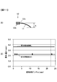
- (A) (B) It is a related figure of the pitch of a deformation
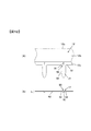
- (A) (B) It is an enlarged plan view of the negative electrode tab vicinity which shows 2nd Embodiment of a deformation
- (A) (B) It is an enlarged plan view of the negative electrode tab vicinity which shows 4th Embodiment of a deformation
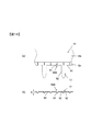
- (A) (B) It is an enlarged plan view of the negative electrode tab vicinity which shows 5th Embodiment of a deformation
- FIG. 1 is a cross-sectional view showing an embodiment of a cylindrical lithium ion secondary battery
- FIG. 2 is an exploded perspective view of the cylindrical lithium ion secondary battery shown in FIG.
- the cylindrical lithium ion secondary battery 1 has dimensions of an outer shape of 40 mm ⁇ and a height of 92 mm, for example.
- This cylindrical lithium ion secondary battery 1 accommodates components for power generation described below in a bottomed cylindrical battery can 2 and a hat-shaped upper lid 3.
- the bottomed cylindrical battery can 2 is formed with a groove 2a protruding toward the inside of the battery can 2 on the upper end side which is the open side.
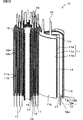
- FIG. 3 is a perspective view showing the details of the structure of the electrode group 10, with a part thereof cut.
- the electrode group 10 has a configuration in which a positive electrode 11, a negative electrode 12, and first and second separators 13 and 14 are wound around an axis 15.
- the shaft core 15 has a hollow cylindrical shape, and the negative electrode 12, the first separator 13, the positive electrode 11, and the second separator 14 are laminated and wound on the shaft core 15 in this order.
- the first separator 13 and the second separator 14 are wound several times (one turn in FIG. 3).
- the outermost periphery is the negative electrode 12 and the first separator 13 wound around the outer periphery.
- the first separator 13 at the outermost periphery is stopped by the adhesive tape 19 (see FIG. 2).
- the positive electrode 11 is formed of an aluminum-based metal foil such as aluminum or aluminum alloy and has a long shape.
- a large number of positive electrode tabs 16 protruding upward in parallel with the shaft core 15 are integrally formed at equal intervals in the positive electrode mixture layer uncoated region 11c.
- the positive electrode mixture is composed of a positive electrode active material, a positive electrode conductive material, and a positive electrode binder.
- the positive electrode active material include lithium cobaltate, lithium manganate, lithium nickelate, lithium composite oxide (lithium oxide containing two or more selected from cobalt, nickel, and manganese). A mixture of these materials may be used, and the mixing ratio is not limited.
- the positive electrode conductive material is not limited as long as it can assist transmission of electrons generated by the occlusion / release reaction of lithium in the positive electrode mixture to the positive electrode 11.
- the positive electrode binder can bind the positive electrode active material and the positive electrode conductive material, and can bind the positive electrode mixture and the positive electrode current collector, and should not deteriorate significantly due to contact with the non-aqueous electrolyte.
- the positive electrode binder include polyvinylidene fluoride (PVDF) and fluororubber.
- the method for forming the positive electrode mixture layer is not limited as long as the positive electrode mixture is formed on the positive electrode.
- the method of forming the positive electrode mixture there is a method of applying a dispersion solution of the constituent material of the positive electrode mixture onto the positive electrode metal foil 11a.
- the method for applying the positive electrode mixture to the positive electrode metal foil 11a include a roll coating method and a slit die coating method.
- NMP N-methylpyrrolidone
- water or the like as a solvent for the dispersion solution
- An example of the coating thickness of the positive electrode mixture is about 40 ⁇ m on one side.
- the negative electrode 12 is formed of a copper-based metal foil such as copper or copper alloy, has a long shape, and the negative electrode metal foil 12a and a negative electrode mixture in which a negative electrode mixture is applied to both surfaces of the negative electrode metal foil 12a. It has a layer application region 12b.
- the lower side edge along the longitudinal direction of the negative electrode metal foil 12a is a negative electrode mixture layer uncoated region 12c where the negative electrode mixture is not applied and the copper-based metal foil is exposed.
- a large number of negative electrode tabs 17 extending in the direction opposite to the positive electrode tab 16 are integrally formed at equal intervals.
- the negative electrode mixture is composed of a negative electrode active material, a negative electrode binder, and a thickener.
- the negative electrode mixture may have a negative electrode conductive material such as acetylene black.
- the negative electrode active material may be amorphous carbon or natural graphite capable of inserting and releasing lithium ions, various artificial graphite materials, carbonaceous materials such as coke, etc. There are no particular restrictions such as fibrous or lump-like shapes.
- SiO, Si alloy, and the like can be cited as materials capable of inserting and removing lithium ions. A mixture of these materials may be used, and the mixing ratio is not limited.
- the method for forming the negative electrode mixture is not limited as long as the negative electrode mixture is formed on the negative electrode metal foil 12a.
- a method of applying the negative electrode mixture to the negative electrode metal foil 12a a method of applying a dispersion solution of a constituent material of the negative electrode mixture onto the negative electrode metal foil 12a can be mentioned.
- the coating method include a roll coating method and a slit die coating method. N-methyl-2-pyrrolidone or water as a dispersion solvent is added to the negative electrode mixture, and the kneaded slurry is uniformly applied to both surfaces of a rolled copper-based metal foil having a thickness of 10 ⁇ m, dried, and then cut.
- An example of the coating thickness of the negative electrode mixture is about 40 ⁇ m on one side.
- the negative electrode tab 17 is integrally formed. All the negative electrode tabs 17 have substantially the same length.
- a deformation reinforcing portion is formed in the negative electrode mixture layer uncoated region 12c. Details of the structure of the deformation reinforcing portion, the manufacturing method, and the like will be described later.
- the widths of the first separator 13 and the second separator 14 are formed larger than the width of the negative electrode mixture layer application region 12b formed on the negative electrode metal foil 12a. Moreover, the width
- region 12b is formed larger than the width
- the separator 13 is, for example, a polyethylene porous film having a thickness of 25 ⁇ m.
- a positive electrode current collecting member 31 is press-fitted into the upper end portion of a hollow cylindrical shaft core 15.
- the positive electrode current collecting member 31 is formed in a substantially disk shape, and is formed of, for example, an aluminum-based metal such as aluminum or an aluminum alloy.
- the positive electrode tab 16 of the positive electrode metal foil 11 a is welded to the upper cylindrical portion 31 a of the positive electrode current collecting member 31. In this case, as illustrated in FIG. 2, the positive electrode tab 16 is overlapped and joined on the upper cylindrical portion 31 a of the positive electrode current collecting member 31.
- a negative electrode current collecting member 21 is press-fitted and fixed to the outer periphery of the lower end portion of the shaft core 15.
- the negative electrode current collecting member 21 is formed in a substantially disk shape, and is formed of, for example, a copper-based metal such as copper or a copper alloy. All of the negative electrode tabs 17 of the negative electrode metal foil 12a are welded to the outer peripheral cylindrical portion 21a of the negative electrode current collecting member 21 by ultrasonic welding or the like.
- the negative electrode tab 17 and the ring-shaped pressing member 22 of the negative electrode metal foil 12a are welded to the outer periphery of the outer peripheral cylindrical portion 21a of the negative electrode current collecting member 21.
- a number of the negative electrode tabs 17 are brought into close contact with the outer periphery of the outer peripheral cylindrical portion 21a of the negative electrode current collecting member 21, and the holding member 22 is wound around the outer periphery of the negative electrode tab 17 to be temporarily fixed, and are welded in this state.
- a negative electrode conducting lead 23 made of copper is welded to the lower surface of the negative electrode current collecting member 21.
- the negative electrode conducting lead 23 is welded to the battery can 2 at the bottom of the battery can 2.
- the battery can 2 is made of carbon steel having a thickness of 0.5 mm, for example, and has a nickel plating on the surface. By using such a material, the negative electrode conducting lead 23 can be welded to the battery can 2 by resistance welding or the like.
- An opening 31 b for inserting an electrode rod (not shown) for welding the negative electrode conducting lead 23 to the battery can 2 is formed in the central portion of the positive electrode current collecting member 31. More specifically, the electrode rod is inserted into the hollow portion of the shaft core 15 from the opening 31b formed in the positive electrode current collecting member 31, and the negative electrode energizing lead 23 is pressed against the inner surface of the bottom of the battery can 2 at the tip thereof. I do.
- a positive electrode tab 16 and a ring-shaped pressing member 32 of the positive electrode metal foil 11 a are welded to the outer periphery of the upper cylindrical portion 31 a of the positive electrode current collecting member 31.
- a number of the positive electrode tabs 16 are brought into close contact with the outer periphery of the upper cylindrical portion 31a of the positive electrode current collecting member 31, and the pressing member 32 is wound around the outer periphery of the positive electrode tab 16 to be temporarily fixed, and is welded in this state.
- a large number of positive electrode tabs 16 are welded to the positive electrode current collector member 31 and a large number of negative electrode tabs 17 are welded to the negative electrode current collector member 21, whereby the positive electrode current collector member 31, the negative electrode current collector member 21 and the electrode group 10 are integrated.
- a unitized power generation unit 20 is configured (see FIG. 2). However, in FIG. 2, for the convenience of illustration, the negative electrode current collecting member 21, the pressing member 22, and the negative electrode energizing lead 23 are illustrated separately from the power generation unit 20.
- a flexible connection member 33 configured by laminating a plurality of aluminum foils is joined to the upper surface of the positive electrode current collecting member 31 by welding one end thereof.
- the connection member 33 can flow a large current by laminating and integrating a plurality of aluminum foils, and is provided with flexibility.
- a ring-shaped insulating plate 41 made of an insulating resin material having a circular opening 41a is placed on the positive electrode current collecting member 31, a ring-shaped insulating plate 41 made of an insulating resin material having a circular opening 41a is placed.
- the insulating plate 41 has an opening 41a (see FIG. 2) and a side portion 41b protruding downward.
- a connecting plate 35 is fitted in the opening 41 a of the insulating plate 41.
- the other end of the flexible connection member 33 is fixed to the lower surface of the connection plate 35 by welding to the connection plate 35.
- connection plate 35 is formed of an aluminum alloy, and has a substantially dish shape in which almost the whole except the central portion is uniform and the central side is bent to a slightly lower position.
- the thickness of the connection plate 35 is, for example, about 1 mm.
- a projection 35 a is formed at the center of the connection plate 35.
- the protrusion 35a of the connection plate 35 is joined to the bottom surface of the center portion of the diaphragm 37 by resistance welding or friction diffusion bonding.
- the diaphragm 37 is formed of an aluminum alloy and has a notch 37a.
- the diaphragm 37 is provided for ensuring the safety of the battery, and has a function of cleaving at the cut 37a and releasing the internal gas when the internal pressure of the battery increases.
- the diaphragm 37 fixes the periphery of the upper lid 3 at the periphery. As shown in FIG. 2, the diaphragm 37 initially has a side portion 37 b erected vertically toward the upper lid 3 side at the peripheral portion.
- the upper lid 3 is accommodated in the side portion 37b, and the side portion 37b is bent and fixed to the upper surface side of the upper lid 3 by caulking.
- the upper lid 3 is made of iron such as carbon steel and is nickel-plated.
- the upper lid 3 includes a disc-shaped peripheral edge 3a that contacts the diaphragm 37 and a headed cylinder 3b that protrudes upward from the peripheral edge 3a. Has a hat shape.
- a plurality of openings 3c are formed in the cylindrical portion 3b.
- the opening 3c is for releasing gas to the outside of the battery when the diaphragm 37 is cleaved by the gas pressure generated inside the battery.
- a gasket 43 is provided so as to cover the side portion 37 b and the peripheral edge portion of the diaphragm 37. As shown in FIG. 2, the gasket 43 is initially formed with an outer peripheral wall portion 43 b erected substantially vertically toward the upper direction on the peripheral edge of the ring-shaped base portion 43 a, and on the inner peripheral side. , And a cylindrical portion 43c formed to hang substantially vertically downward from the base portion 43a.
- the outer peripheral wall 43b of the gasket 43 is bent together with the battery can 2 by pressing or the like, and the diaphragm 37 and the upper lid 3 are crimped by the base 43a and the outer peripheral wall 43b so as to be pressed in the axial direction. Thereby, the upper lid 3 and the diaphragm 37 are fixed to the battery can 2 via the gasket 43.
- a predetermined amount of non-aqueous electrolyte is injected into the battery can 2.
- the non-aqueous electrolyte it is preferable to use a solution in which a lithium salt is dissolved in a carbonate solvent.
- the lithium salt include lithium fluorophosphate (LiPF6), lithium fluoroborate (LiBF4), and the like.
- carbonate solvents include ethylene carbonate (EC), dimethyl carbonate (DMC), propylene carbonate (PC), methyl ethyl carbonate (MEC), or a mixture of solvents selected from one or more of the above solvents, Is mentioned.
- FIG. 4 is a plan view showing a state in which the terminal side of the electrode group shown in FIG. 3 is expanded
- FIG. 5 is a perspective view for explaining a method of manufacturing the electrode group shown in FIG. 6 is an external perspective view showing a completed state of the electrode group shown in FIG.
- the electrode group 10 has a first separator 13 wound on the outermost periphery when viewed from the end side, a negative electrode 12 wound on the inner side, and a second separator on the inner side of the negative electrode 12.
- the separator 14 is wound, and the positive electrode 11 is wound inside the second separator 14.
- the length of the first separator 13 is the longest and the terminal edge 13 a is located farthest from the shaft core 15 in the radial direction.
- the second separator 14 is long next to the first separator 13, and the end edge 14 a thereof is located slightly closer to the axis 15 than the end edge 13 a of the first separator 13.
- the positive electrode 11 and the negative electrode 12 are longer in the negative electrode 12.
- the negative electrode 12 is shorter than the second separator 14, and the terminal edge 12 d of the negative electrode 12 is located closer to the shaft core 15 than the terminal edge 14 a of the second separator 14.
- the positive electrode 11 is shorter than the negative electrode 12, and the terminal edge 11 d is closest to the shaft core 15.
- the widths of the first separator 13 and the second separator 14 are the same, both of which are larger than the widths of the positive electrode 11 and the negative electrode 12, the root of the positive electrode tab 16 of the positive electrode 11 and the negative electrode of the negative electrode 12. Covers the base of the tab 17. However, the portion on the tip side from the root of the positive electrode tab 16 and the portion on the tip side from the root of the negative electrode tab 17 extend to the outside of the first separator 13 and the second separator 14.
- the positive electrode tab 16 of the positive electrode 11 and the negative electrode tab 17 of the negative electrode 12 are arranged at a predetermined pitch (23 mm in this embodiment).
- FIG. 5 is a perspective view showing the tip side in a state where the first separator 13, the second separator 14, the negative electrode 12 and the positive electrode 11 are wound around the shaft core 15.
- the leading edges (not shown) of the first separator 13 and the second separator 14 are welded to the shaft core 15 and wound around the shaft core 1 to several times. In this case, the leading edge of the first separator 13 and the leading edge of the second separator 14 may be aligned or shifted.
- the negative electrode 12 is sandwiched between the second separator 14 and the first separator 13.
- the positive electrode 11 is sandwiched between the first separator 13 and the second separator 14. At this time, the leading edge 11 e of the positive electrode 11 is positioned on the outer peripheral side of the leading edge 12 e of the negative electrode 12.
- the rotation shaft of the winding device when the rotation shaft of the winding device is connected to the shaft core 15 and the shaft core 15 is driven to rotate, the negative electrode 12 and the positive electrode 11 are connected to the first separator 13 and the second separator 14. And is wound around the shaft core 15 with a predetermined rotational torque. Then, the outer periphery of the outermost first separator 13 is bonded with the adhesive tape 19.
- FIG. 6 is a perspective view showing a completed state of the electrode group 10 manufactured as described above.
- the positive electrode mixture layer application region 11b, the positive electrode mixture layer non-application region 11c, the negative electrode mixture layer application region 12b, and the negative electrode mixture layer non-application region 12c are all covered with the first and second separators 13 and 14. .
- the first separator 13 is exposed at the outermost periphery of the electrode group 10, and the outermost peripheral end portion of the first separator 13 is fastened with an adhesive tape.
- the positive electrode tab 16 and the negative electrode tab 17 are exposed from the first separator 13 on the tip side with respect to the root portion.
- a deformation reinforcing portion is formed in each of the positive electrode mixture layer uncoated region 11c and the negative electrode mixture layer uncoated region 12c.
- the deformation reinforcing portion is formed in the process of manufacturing the electrode group 10. The structure of the positive electrode mixture layer uncoated region 11 c and the negative electrode mixture layer uncoated region 12 c together with the manufacturing method of the electrode group 10 and A method for forming the deformation reinforcing portion will be described.
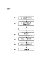
- FIG. 7 is a process flow diagram showing a method of manufacturing a cylindrical lithium ion secondary battery
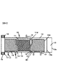
- FIG. 8 is a plan view for explaining a method of forming a deformation reinforcing portion and a tab.
- the manufacturing method of the cylindrical lithium ion secondary battery of this embodiment is demonstrated centering on the preparation methods of the electrode group 10.
- step S1 the positive / negative electrode mixture layer is applied to both the front and back surfaces of the positive / negative electrode metal foils 11a, 12a to form the positive / negative electrode mixture layer application regions 11b, 12b. That is, the positive electrode mixture layer uncoated areas 11c where the positive electrode metal foil 11a is exposed without forming the positive electrode mixture are formed on one side edge along the longitudinal direction of the positive electrode metal foil 11a on both the front and back surfaces of the positive electrode metal foil 11a. Thus, the positive electrode mixture is applied to form the positive electrode mixture layer application region 11b (see FIG. 3).
- the negative electrode mixture layer uncoated region 12c where the negative electrode mixture is not applied to the one side edge 61 along the longitudinal direction of the negative electrode metal foil 12a on both the front and back surfaces of the negative electrode metal foil 12a and the negative electrode metal foil 12a is exposed.
- the negative electrode mixture is applied to form the negative electrode mixture layer application region 12b (see FIGS. 3 and 9).
- step S2 positive and negative tabs 16 and 17 are formed.
- the positive electrode metal foil 11a the positive electrode metal foil 11a is cut so that the positive electrode tabs 16 are arranged at a predetermined pitch along one side edge of the positive electrode mixture layer uncoated region 11c. Thereby, the positive electrode 11 is produced.
- the negative electrode metal foil 12a the negative electrode metal foil 12a is cut so that the negative electrode tabs 17 are arranged at a predetermined pitch along one side edge of the negative electrode mixture layer uncoated region 12c. Thereby, the negative electrode 12 is produced.
- the deformation reinforcing portion forming device 100 and the tab forming device 200 are arranged along one side edge of the negative electrode mixture layer uncoated region 12 c of the negative electrode metal foil 12 a.
- the deformation reinforcing portion forming apparatus 100 includes a die-shaped roll 100a and a receiving-side roll 100b having bending projections 112 at equal intervals.
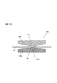
- FIG. 10 is an enlarged cross-sectional view of the bending protrusion 112 of the deformation reinforcing portion forming apparatus 100 in the negative electrode metal foil 12a.
- the mold-equipped roll 100a includes a bending protrusion 112, and the bending protrusion 112 has one side edge 61 from the vicinity of the boundary line between the negative electrode mixture layer application region 12b and the negative electrode mixture layer non-application region 12c. The length is extended to the vicinity.
- the receiving-side roll 100b includes a resin elastic body so as to be deformed in accordance with its shape when the bending protrusion 112 is pushed.
- the negative electrode mixture layer non-application region 12c of the negative electrode metal foil 12a having the negative electrode mixture layer application region 12b formed on both the front and back surfaces is arranged so that the mold roll 100a and the receiving roll 100b pass, and the direction of the arrow in FIG.
- the tab forming apparatus 200 includes a roll-shaped punch 200a and a die 200b so that tab forming can be continuously performed.
- the punch 200 a includes a cutting protrusion 212 having a shape corresponding to the outer diameter of the negative electrode tab 17.
- the upper surface of the negative electrode metal foil 12a formed with the deformation reinforcing portion by the deformation reinforcing portion forming apparatus 100 is arranged so that the punch 200a and the die 200b pass through, and the negative electrode 12 is moved in the arrow direction Y of FIG. As the tab forming apparatus 200 moves while rotating, the negative electrode metal foil 12a is cut, and the negative electrode tab 17 can be formed continuously.
- the positive electrode tab 16 can also be formed with the positive electrode 11 with the same manufacturing method.
- FIG. 9A is an enlarged plan view in the vicinity of the negative electrode tab
- FIG. 9B is a side view in the vicinity of the negative electrode tab shown in FIG. 9A
- FIG. 10 is a method for forming the deformation reinforcing portion. It is an expanded sectional view explaining these.
- the negative electrode tab 17 is formed on the negative electrode metal foil 12a of the negative electrode 12 integrally with the negative electrode mixture layer uncoated region 12c along a side edge 61 (see FIG. 9) in the longitudinal direction of the negative electrode metal foil 12a. Arranged at pitch.
- the negative electrode mixture layer uncoated region 12c includes a valley fold portion 50 (deformation reinforcing portion) in which a concave portion is formed, as shown in FIGS. 9 (A) and 9 (B). That is, the ridge line 51 of the valley fold part 50 along the extending direction of the negative electrode tab 17 is one side of the negative electrode mixture layer uncoated region from the vicinity of the boundary between the negative electrode mixture layer coated region 12b and the negative electrode mixture layer uncoated region 12c. It is formed extending to the vicinity of the edge 61. From the ridge line 51 toward the surface 62 of the negative electrode mixture layer uncoated region 12c, a substantially flat slope having an upward slope is formed.
- the ridge line 51 protrudes from the surface 62 of the negative electrode mixture layer uncoated region 12c by a predetermined height h.
- the negative electrode mixture layer non-applied region 12c has a shape including the valley fold portion 50, and its rigidity is larger than that of the planar shape not having the valley fold portion 50. Since the angle at which the layer uncoated region 12c hangs down, the amount of sag of the negative electrode tab 17 connected to the negative electrode mixture layer uncoated region 12c can be reduced.
- the positive electrode mixture layer non-applied region 11 c has a deformation reinforcing portion in which a concave portion is formed, and the amount of drooping of the positive electrode tab 16 can be reduced.
- Step S3 of FIG. 7 the positive electrode 11 and the negative electrode 12 are heated, and the positive electrode mixture in the positive electrode mixture layer application region 11b and the negative electrode mixture in the negative electrode mixture layer application region 12b are dried.
- step S4 the positive electrode 11 and the negative electrode 12 are wound around the shaft core 15 with the first and second separators 13 and 14 interposed therebetween to produce the electrode group 10.
- the negative electrode 12 may have the valley fold side directed toward the axis 15, or the mountain fold side opposed to the axis 15.
- the rigidity of the narrow and long negative electrode tab 17 is lowered. Due to the decrease in rigidity, the negative electrode tab 17 is liable to be twisted, collapsed, bent or the like due to its own weight or kinetic energy of the molding process or the winding process.
- the negative electrode tab 17 connected to the negative electrode mixture layer non-application region 12c is preliminarily increased in rigidity by forming the valley fold portion 50 in the negative electrode mixture layer non-application region 12c. It is difficult for drooping, twisting, falling or folding. Similarly, the positive electrode tab 16 is unlikely to sag, twist, fall or bend.
- step S5 the power generation unit 20 is assembled.
- a negative electrode current collecting member 21 is attached to the lower part of the shaft core 15 of the electrode group 10.
- the negative electrode tab 17 is brought into close contact with the entire periphery of the outer peripheral cylindrical portion 21 a of the negative electrode current collecting member 21, and the holding member 22 is wound around the outer periphery of the negative electrode tab 17.
- the negative electrode tab 17 and the pressing member 22 are welded to the negative electrode current collecting member 21 by ultrasonic welding or the like.
- the negative electrode conducting lead 23 is welded to the negative electrode current collecting member 21 so as to straddle the lower end surface of the shaft core 15 and the negative electrode current collecting member 21.
- connection member 33 is welded to the positive electrode current collector 31 by, for example, ultrasonic welding.
- the lower part of the positive electrode current collecting member 31 to which the connecting member 33 is welded is attached to the upper end side of the shaft core 15.
- the positive electrode tab 16 is brought into close contact with the entire periphery of the upper cylindrical portion 31 a of the positive electrode current collecting member 31, and the pressing member 32 is wound around the outer periphery of the positive electrode tab 16.
- the positive electrode tab 16 and the pressing member 32 are welded to the positive electrode current collecting member 31 by ultrasonic welding or the like. In this way, the power generation unit 20 illustrated in FIG. 2 is produced.
- step S6 the power generation unit 20 is accommodated in the battery can 2, and the cylindrical lithium ion secondary battery 1 is assembled.
- the power generation unit 20 is accommodated in the battery can 2 and the negative electrode conducting lead 23 of the power generation unit 20 is welded to the inner surface of the bottom of the battery can 2 by resistance welding or the like.
- a part on the upper end side of the battery can 2 is drawn and protrudes inward to form a substantially V-shaped groove 2a on the outer surface.
- a predetermined amount of non-aqueous electrolyte is injected into the battery can 2 in which the power generation unit 20 is accommodated.
- the upper lid 3 is fixed to the diaphragm 37.
- the diaphragm 37 and the upper lid 3 are fixed by caulking or the like.
- the side portion 37b of the diaphragm 37 is initially formed perpendicular to the base portion 37a, the peripheral edge portion 3a of the upper lid 3 is disposed in the side portion 37b of the diaphragm 37.
- the side portion 37b of the diaphragm 37 is deformed by a press or the like, and the upper surface and the lower surface of the peripheral portion of the upper lid 3 and the outer peripheral side surface are covered and pressed.
- the connection plate 35 is fitted and attached to the opening 41 a of the insulating plate 41.
- connection board 35 is welded to the bottom face of the diaphragm 37 with which the upper cover 3 was fixed.
- welding method in this case, resistance welding or friction diffusion bonding can be used.
- the gasket 43 is accommodated on the groove 2 a of the battery can 2.
- the gasket 43 in this state has a structure having an outer peripheral wall 43b perpendicular to the base 43a above the ring-shaped base 43a. With this structure, the gasket 43 remains inside the upper portion of the groove 2 a of the battery can 2.
- An example of the material of the gasket 43 is PFA (polytetrafluoroethylene).
- the outer peripheral wall 43b of the gasket 43 is bent together with the battery can 2 by pressing or the like, and the diaphragm 37 and the upper lid 3 are crimped by the base 43a and the outer peripheral wall 43b so as to be pressed in the axial direction. Thereby, the upper cover 3 and the diaphragm 37 are fixed to the battery can 2 via the gasket 43, and the cylindrical lithium ion secondary battery 1 is produced.
- step S7 a charge / discharge test of the produced cylindrical lithium ion secondary battery 1 is performed. Those satisfying predetermined characteristics in this test are selected as non-defective products.
- (Deformation reinforcement) 11A and 11B the relationship between the pitch w of the deformation reinforcing portion and the sag amount X of the tab portions (the positive electrode tab 16 and the negative electrode tab 17) when the negative electrode mixture layer uncoated region 12c is provided with the deformation reinforcing portion.
- the figure is shown.
- the sagging amount X is obtained when the negative electrode mixture layer application region 12b of the negative electrode 12 is placed on a flat surface, and the negative electrode mixture layer non-application region 12c and the negative electrode tab 17 are hung by their own weights.
- the distance from the boundary surface of the negative electrode mixture layer application region 12b and the negative electrode mixture layer non-application region 12c to the tip of the negative electrode tab 17 is shown.
- the sag amount X of the tab portion is 3.7 mm.
- the deformation reinforcing portion is provided in the negative electrode mixture layer uncoated region 12c, if the pitch w of the deformation reinforcing portion is 23 mm or less, which is the tab interval, the sag amount X is 2.1 to 2.3 mm. X is suppressed.
- the adjacent interval between the deformation reinforcing portions is equal to or less than the adjacent interval between the tabs.
- the range in which the sagging amount X of the tab portion varies increases, but when there is a deformation reinforcing portion in the negative electrode mixture layer uncoated region 12c, the tab portion Since the range in which the amount of drooping X varies varies, stable reinforcement is possible by providing the deformation reinforcing portion in the negative electrode mixture layer uncoated region 12c.
- the pitch w of the deformation reinforcing portion provided in the negative electrode mixture layer uncoated region 12c is equal to or less than the tab interval, sufficient rigidity is ensured, so that the sagging amount X can be suppressed.
- FIGS. 12A and 12B are views showing a second embodiment of the deformation reinforcing portion.
- 12A is an enlarged plan view near the tab
- FIG. 12B is a side view of FIG.
- the structure of the cylindrical lithium ion secondary battery and the method of manufacturing the cylindrical lithium ion secondary battery are the same as those in the first embodiment described with reference to FIGS.
- the negative electrode tabs 17 are arranged at a predetermined pitch along one side edge 61 in the longitudinal direction of the negative electrode metal foil 12a integrally with the negative electrode mixture layer uncoated region 12c. Yes.
- the deformation reinforcing portion is provided at the position of the negative electrode mixture layer uncoated region 12c corresponding to the position of the negative electrode tab 17, as shown in FIGS. 12 (A) and 12 (B). In the deformation reinforcing portion, a concave portion is formed by the valley fold portion 50.
- the ridge line 51 of the valley fold part 50 along the extending direction of the negative electrode tab 17 is from the vicinity of the boundary between the negative electrode mixture layer application region 12b and the negative electrode mixture layer non-application region 12c to the negative electrode tab 17 in the negative electrode mixture layer non-application region. It is formed to extend to the vicinity of the base. From the ridge line 51 toward the surface 62 of the negative electrode mixture layer uncoated region 12c, a substantially flat slope having an upward slope is formed. The ridge line 51 protrudes from the surface 62 of the negative electrode mixture layer uncoated region 12c by a predetermined height h.
- the negative electrode mixture layer non-applied region 12c has a shape including the valley fold portion 50 near the base of the negative electrode tab 17, so that its rigidity is greater than that of a planar shape having no valley fold portion 50. Since the angle at which the negative electrode mixture layer uncoated region 12c hangs down due to gravity or the like, the amount of sag of the negative electrode tab 17 connected to the negative electrode mixture layer uncoated region 12c can be reduced.
- the positive electrode mixture layer non-applied region 11 c has a deformation reinforcing portion in which a concave portion is formed, and the amount of drooping of the positive electrode tab 16 can be reduced.
- FIGS. 13A and 13B are views showing a third embodiment of the deformation reinforcing portion.
- FIG. 13A is an enlarged plan view near the tab
- FIG. 13B is a side view of FIG.
- the structure of the cylindrical lithium ion secondary battery and the method of manufacturing the cylindrical lithium ion secondary battery are the same as those in the first embodiment described with reference to FIGS.
- the negative electrode tabs 17 are arranged at a predetermined pitch along one side edge 61 in the longitudinal direction of the negative electrode metal foil 12a integrally with the negative electrode mixture layer uncoated region 12c. Yes.
- the deformation reinforcing portion is formed at the position of the negative electrode mixture layer uncoated region 12c corresponding to the position of the negative electrode tab 17 and at the central portion of the negative electrode tab 17. Provided. In the deformation reinforcing portion, a concave portion is formed by the valley fold portion 50.
- the ridge line 51 of the valley fold 50 along the direction in which the negative electrode tab 17 extends extends from the vicinity of the boundary between the negative electrode mixture layer application region 12b and the negative electrode mixture layer non-application region 12c to the negative electrode mixture layer non-application region 12c. It is formed to extend to the tip of the tab 17. From the ridge line 51 toward the surface 62 of the negative electrode mixture layer uncoated region 12c, a substantially flat slope having an upward slope is formed. The ridge line 51 protrudes from the surface 62 of the negative electrode mixture layer uncoated region 12c by a predetermined height h.
- the deformation reinforcing portion has a shape including the root of the negative electrode tab 17 in the negative electrode mixture layer uncoated region 12 c and the valley fold portion 50 in the negative electrode tab 17. This can improve the rigidity of the negative electrode tab 17 together with the rigidity of the negative electrode mixture layer uncoated region 12c, so that it is larger than the planar shape without the valley folds 50, and the negative electrode mixture layer uncoated region 12c by gravity or the like. Since the sagging angle is reduced, the sagging amount of the negative electrode tab 17 connected to the negative electrode mixture layer uncoated region 12c can be reduced. Similarly, the positive electrode mixture layer non-applied region 11 c has a deformation reinforcing portion in which a concave portion is formed, and the amount of drooping of the positive electrode tab 16 can be reduced.
- FIGS. 14A and 14B are views showing a fourth embodiment of the deformation reinforcing portion.
- FIG. 14 (A) is an enlarged plan view near the tab
- FIG. 14 (B) is a side view of FIG. 14 (A).
- the structure of the cylindrical lithium ion secondary battery and the method of manufacturing the cylindrical lithium ion secondary battery are the same as those in the first embodiment described with reference to FIGS.
- the negative electrode tabs 17 are arranged at a predetermined pitch along the one side edge 61 in the longitudinal direction of the negative electrode metal foil 12a integrally with the negative electrode mixture layer uncoated region 12c.
- the deformation reinforcing portion includes the negative electrode mixture layer uncoated region 12 c corresponding to the position of the negative electrode tab 17, and between the negative electrode tab 17 and the negative electrode tab 17.
- a concave portion is formed by a trapezoidal portion 50A having a substantially trapezoidal cross section. The trapezoidal portion 50A is formed to protrude from the surface 62 of the negative electrode mixture layer uncoated region 12c by a predetermined height h.
- FIG. 15 is an enlarged cross-sectional view for explaining a method of forming the deformation reinforcing portion of the fourth embodiment.
- the die roll 100a1 includes a folding projection 112A having a substantially trapezoidal cross section, and when the folding projection 112A is pushed in, the negative electrode mixture layer uncoated region 12c A trapezoidal portion 50A is formed.
- the deformation reinforcing portion has a trapezoidal shape, the rigidity of the negative electrode mixture layer uncoated region 12c is improved, and the angle at which the negative electrode mixture layer uncoated region 12c hangs down due to gravity or the like. And the drooping amount of the negative electrode tab 17 connected to the negative electrode mixture layer non-application area
- region 12c can be made small.
- the positive electrode mixture layer non-applied region 11 c has a deformation reinforcing portion in which a concave portion is formed, and the amount of drooping of the positive electrode tab 16 can be reduced.
- FIGS. 16A and 16B are views showing a fifth embodiment of the deformation reinforcing portion.
- FIG. 15A is an enlarged plan view near the tab
- FIG. 16B is a side view of FIG.
- the structure of the cylindrical lithium ion secondary battery and the method of manufacturing the cylindrical lithium ion secondary battery are the same as those in the first embodiment described with reference to FIGS.
- the negative electrode tabs 17 are arranged at a predetermined pitch along one side edge 61 in the longitudinal direction of the negative electrode metal foil 12a integrally with the negative electrode mixture layer uncoated region 12c.
- the deformation reinforcing portion includes the negative electrode mixture layer uncoated region 12c corresponding to the position of the negative electrode tab 17, and between the negative electrode tab 17 and the negative electrode tab 17.
- the deformation reinforcing portion has a recess formed by a hook-shaped portion 50B having a substantially hook-shaped cross section.
- the bowl-shaped portion 50B is formed to protrude from the surface 62 of the negative electrode mixture layer uncoated region 12c by a predetermined height h.
- FIG. 17 is an enlarged cross-sectional view for explaining a method of forming the deformation reinforcing portion of the fifth embodiment.
- the die roll 100a2 includes a folding projection 112B having a substantially bowl-shaped cross section, and when the folding projection 112B is pushed in, the negative electrode mixture layer uncoated region 12c The bowl-shaped part 50B is formed.
- the deformation reinforcing portion has a bowl shape, the rigidity of the negative electrode mixture layer uncoated region 12c is improved, and the angle at which the negative electrode mixture layer uncoated region 12c hangs down due to gravity or the like. Since the deformation reinforcing portion has a hook shape, the bent portion is eliminated, and the deformation reinforcing portion can be prevented from being broken or perforated. And the drooping amount of the negative electrode tab 17 connected to the negative electrode mixture layer non-application area
- FIG. 18 is an external perspective view showing a state where the winding end side of the electrode group 70 of the square secondary battery is developed.
- the electrode group 70 is formed by winding a positive electrode 71 and a negative electrode 72 in a flat shape around a shaft core (not shown) with first and second separators 73 and 74 interposed therebetween.
- Reference numeral 70 a is a hollow portion having a width corresponding to the thickness of the axial center of the electrode group 70.
- a positive electrode mixture is applied to both the front and back surfaces of a positive electrode metal foil made of an aluminum foil or the like to form a positive electrode mixture layer application region 71b.
- a positive electrode mixture layer uncoated region 71c where the positive metal foil is exposed is formed on one side edge of the positive metal foil.
- the positive electrode tab 71d is integrally connected to the positive electrode mixture layer uncoated region 71c and protrudes in a direction perpendicular to the longitudinal direction of the positive electrode metal foil.
- the positive electrode tabs 71d are arranged at a predetermined pitch along the longitudinal direction of the positive electrode metal foil.
- the deformation reinforcing portion is provided in the positive electrode mixture layer uncoated region 71c corresponding to the position of the positive electrode tab 71d.
- a concave portion is formed by the valley fold portion 71e.
- the deformation reinforcing portion may be a trapezoidal portion having a substantially trapezoidal cross section and a bowl-shaped portion having a substantially bowl-shaped cross section. Further, it is desirable that the adjacent interval between the deformation reinforcing portions is equal to or less than the adjacent interval between the positive electrode tabs 71d.
- the negative electrode 72 is formed by applying a negative electrode mixture on both front and back surfaces of a negative electrode metal foil made of, for example, copper foil or the like to form a negative electrode mixture layer application region 72b.
- a negative electrode mixture layer uncoated region 72c where the negative electrode metal foil is exposed is formed on one side edge of the negative electrode metal foil and in a direction opposite to the positive electrode mixture layer uncoated region 71c.
- the negative electrode tab 72d is integrally connected to the negative electrode mixture layer uncoated region 72c and protrudes in a direction perpendicular to the longitudinal direction of the negative electrode metal foil and in a direction opposite to the positive electrode tab 71d.
- the negative electrode tabs 72d are arranged at a predetermined pitch along the longitudinal direction of the negative electrode metal foil.
- the deformation reinforcing portion is provided in the negative electrode mixture layer uncoated region 72c corresponding to the position of the negative electrode tab 72d.
- a concave portion is formed by the valley fold portion 72e.
- the deformation reinforcing portion may be a trapezoidal portion having a substantially trapezoidal cross section and a bowl-shaped portion having a substantially bowl-shaped cross section.
- it is desirable that the interval between adjacent deformation reinforcing portions is equal to or less than the interval between adjacent negative electrode tabs 72d.
- the negative electrode mixture layer uncoated region 72c has a shape including the valley folds 72e near the base of the negative electrode tab 72d, so that the rigidity thereof is higher than that of a planar shape having no valley folds 72e. Since the drooping angle of the negative electrode mixture layer uncoated region 72c is reduced due to gravity or the like, the amount of droop of the negative electrode tab 72d connected to the negative electrode mixture layer uncoated region 72c can be reduced. Similarly, the positive electrode mixture layer non-application region 71c has a deformation reinforcing portion in which a concave portion is formed, and the amount of drooping of the positive electrode tab 71d can be reduced.
- the rigidity of the mixture layer non-application region can be increased. For this reason, the sagging angle of the mixture layer uncoated area can be suppressed, and the sagging amount of the tab connected to the uncoated area can be suppressed. It will be difficult to break. As a result, the efficiency of the manufacturing process of the secondary battery can be improved.
- the secondary battery (1, 4) includes a mixture layer application region (11b, 12b, 71b, 72b), a mixture layer non-application region (11c, 12c, 71c, 72c), and a mixture layer not applied
- the present invention can be implemented by modifying the first to sixth embodiments described above as follows.
- (1) in the above embodiment, the cylindrical lithium ion secondary battery and the square secondary battery have been described as examples. However, the mixture layer application region, the mixture layer non-application region, and the mixture layer non-application region are connected. If it is provided with the electrode which has the tab part which is made, it will not be limited to a cell shape, For example, this invention is applicable also to a laminate-type secondary battery.
- the deformation reinforcing portion is described as an example of a trapezoidal portion having a substantially trapezoidal section, a bowl-shaped portion having a substantially bowl-shaped cross section, and a valley fold portion. Other shapes may be used as long as the uncoated region is reinforced. Further, the deformation reinforcing portion has a recess formed in parallel with the extending direction of the positive electrode tab / negative electrode tab, but it is not necessarily parallel, and for example, has an inclination angle with respect to the extending direction of the positive electrode tab / negative electrode tab. It may be formed.
- a lithium ion secondary battery has been described as an example of a secondary battery, but the present invention is not limited to a lithium ion secondary battery, such as a nickel metal hydride battery or a nickel cadmium battery.
- the present invention can also be applied to other secondary batteries. It can also be applied to lithium ion capacitors and electric double layer capacitors.
- the present invention is not limited to the above-described embodiment, and other forms conceivable within the scope of the technical idea of the present invention are also included in the scope of the present invention as long as the characteristics of the present invention are not impaired. . Moreover, it is good also as a structure which combined the above-mentioned embodiment and a some modification.
Landscapes
- Engineering & Computer Science (AREA)
- Chemical & Material Sciences (AREA)
- Chemical Kinetics & Catalysis (AREA)
- Electrochemistry (AREA)
- General Chemical & Material Sciences (AREA)
- Power Engineering (AREA)
- Microelectronics & Electronic Packaging (AREA)
- Manufacturing & Machinery (AREA)
- Connection Of Batteries Or Terminals (AREA)
- Battery Electrode And Active Subsutance (AREA)
- Electric Double-Layer Capacitors Or The Like (AREA)
- Secondary Cells (AREA)
Abstract
La présente invention traite les problèmes selon lesquels une région sans revêtement de couche de mélange, qui est une base de fixation pour des parties languette, s'affaisse dans une large mesure, et selon lesquels l'effet de suppression est réduit en termes de quantité d'affaissement pour la totalité des parties languette. Des languettes d'électrode négative (17) sont agencées en un corps unique ayant une région sans revêtement de couche de mélange d'électrode négative (12c), sur une feuille métallique d'électrode négative (12a) à partir d'une électrode de pôle négatif (12), à un pas prédéterminé le long d'un bord latéral (61) de la feuille métallique d'électrode négative (12a) dans le sens de sa longueur. La région sans revêtement de couche de mélange (12c) comprend des parties creux-pli (50) (parties de renforcement déformées), un creux étant formé dans chacune de ces dernières. Grâce à une forme comprenant des parties creux-pli (50), la rigidité de la région sans revêtement de couche de mélange d'électrode négative (12c) est importante par comparaison à celle d'une forme plane n'ayant pas de partie creux-pli (50), conduisant à un petit angle d'affaissement provoqué par la gravité, ou analogue, de la région sans revêtement de couche de mélange d'électrode négative (12c), permettant ainsi à la quantité d'affaissement d'être petite pour les languettes d'électrode négative (17) connectées à la région sans revêtement de couche de mélange d'électrode négative (12c).
Priority Applications (2)
| Application Number | Priority Date | Filing Date | Title |
|---|---|---|---|
| JP2018505323A JP6505943B2 (ja) | 2016-03-17 | 2017-02-01 | 二次電池 |
| CN201780007427.6A CN108701856B (zh) | 2016-03-17 | 2017-02-01 | 二次电池 |
Applications Claiming Priority (2)
| Application Number | Priority Date | Filing Date | Title |
|---|---|---|---|
| JP2016053387 | 2016-03-17 | ||
| JP2016-053387 | 2016-03-17 |
Publications (1)
| Publication Number | Publication Date |
|---|---|
| WO2017159094A1 true WO2017159094A1 (fr) | 2017-09-21 |
Family
ID=59851873
Family Applications (1)
| Application Number | Title | Priority Date | Filing Date |
|---|---|---|---|
| PCT/JP2017/003506 Ceased WO2017159094A1 (fr) | 2016-03-17 | 2017-02-01 | Batterie rechargeable |
Country Status (3)
| Country | Link |
|---|---|
| JP (1) | JP6505943B2 (fr) |
| CN (1) | CN108701856B (fr) |
| WO (1) | WO2017159094A1 (fr) |
Cited By (2)
| Publication number | Priority date | Publication date | Assignee | Title |
|---|---|---|---|---|
| CN113193163A (zh) * | 2021-04-28 | 2021-07-30 | 宁德新能源科技有限公司 | 电芯及用电装置 |
| WO2021251121A1 (fr) * | 2020-06-09 | 2021-12-16 | 株式会社村田製作所 | Batterie secondaire, dispositif électronique et outil électrique |
Families Citing this family (3)
| Publication number | Priority date | Publication date | Assignee | Title |
|---|---|---|---|---|
| KR102804867B1 (ko) * | 2019-05-22 | 2025-05-09 | 삼성에스디아이 주식회사 | 이차전지 |
| JP7600979B2 (ja) * | 2021-12-28 | 2024-12-17 | トヨタ自動車株式会社 | 電池 |
| EP4618200A1 (fr) * | 2024-03-12 | 2025-09-17 | SK On Co., Ltd. | Électrode pour batterie secondaire, ensemble électrode pour batterie secondaire la comprenant et batterie secondaire la comprenant |
Citations (5)
| Publication number | Priority date | Publication date | Assignee | Title |
|---|---|---|---|---|
| JP2006012827A (ja) * | 2004-06-23 | 2006-01-12 | Samsung Sdi Co Ltd | 二次電池 |
| JP2011165515A (ja) * | 2010-02-10 | 2011-08-25 | Sanyo Electric Co Ltd | 角形密閉二次電池及び角形密閉二次電池の製造方法 |
| JP2012226862A (ja) * | 2011-04-15 | 2012-11-15 | Toyota Motor Corp | モノポーラ型固体電池、積層型固体電池および移動体 |
| WO2014034708A1 (fr) * | 2012-08-29 | 2014-03-06 | シャープ株式会社 | Plaque électrode et batterie secondaire |
| JP2014082055A (ja) * | 2012-10-15 | 2014-05-08 | Hitachi Vehicle Energy Ltd | 円筒形蓄電素子 |
Family Cites Families (5)
| Publication number | Priority date | Publication date | Assignee | Title |
|---|---|---|---|---|
| JPS57141863A (en) * | 1981-02-25 | 1982-09-02 | Shin Kobe Electric Mach Co Ltd | Group welding method of lead battery electrode |
| CN2836245Y (zh) * | 2006-01-20 | 2006-11-08 | 惠州市德赛电池有限公司 | 一种电池导出端子结构 |
| CN2938435Y (zh) * | 2006-08-14 | 2007-08-22 | 比亚迪股份有限公司 | 一种卷绕式锂离子电池 |
| JP2013105623A (ja) * | 2011-11-14 | 2013-05-30 | Toyota Industries Corp | 二次電池用電極及び二次電池並びに車両 |
| JP5974704B2 (ja) * | 2012-07-23 | 2016-08-23 | 株式会社豊田自動織機 | 蓄電装置、二次電池、及び、積層型の電極組立体の製造方法 |
-
2017
- 2017-02-01 CN CN201780007427.6A patent/CN108701856B/zh active Active
- 2017-02-01 JP JP2018505323A patent/JP6505943B2/ja active Active
- 2017-02-01 WO PCT/JP2017/003506 patent/WO2017159094A1/fr not_active Ceased
Patent Citations (5)
| Publication number | Priority date | Publication date | Assignee | Title |
|---|---|---|---|---|
| JP2006012827A (ja) * | 2004-06-23 | 2006-01-12 | Samsung Sdi Co Ltd | 二次電池 |
| JP2011165515A (ja) * | 2010-02-10 | 2011-08-25 | Sanyo Electric Co Ltd | 角形密閉二次電池及び角形密閉二次電池の製造方法 |
| JP2012226862A (ja) * | 2011-04-15 | 2012-11-15 | Toyota Motor Corp | モノポーラ型固体電池、積層型固体電池および移動体 |
| WO2014034708A1 (fr) * | 2012-08-29 | 2014-03-06 | シャープ株式会社 | Plaque électrode et batterie secondaire |
| JP2014082055A (ja) * | 2012-10-15 | 2014-05-08 | Hitachi Vehicle Energy Ltd | 円筒形蓄電素子 |
Cited By (6)
| Publication number | Priority date | Publication date | Assignee | Title |
|---|---|---|---|---|
| WO2021251121A1 (fr) * | 2020-06-09 | 2021-12-16 | 株式会社村田製作所 | Batterie secondaire, dispositif électronique et outil électrique |
| JPWO2021251121A1 (fr) * | 2020-06-09 | 2021-12-16 | ||
| JP7396481B2 (ja) | 2020-06-09 | 2023-12-12 | 株式会社村田製作所 | 二次電池、電子機器及び電動工具 |
| US12362441B2 (en) | 2020-06-09 | 2025-07-15 | Murata Manufacturing Co., Ltd. | Secondary battery, electronic device, and electric tool |
| CN113193163A (zh) * | 2021-04-28 | 2021-07-30 | 宁德新能源科技有限公司 | 电芯及用电装置 |
| US12580278B2 (en) | 2021-04-28 | 2026-03-17 | Ningde Amperex Technology Limited | Battery cell and electric apparatus |
Also Published As
| Publication number | Publication date |
|---|---|
| CN108701856A (zh) | 2018-10-23 |
| CN108701856B (zh) | 2021-07-20 |
| JP6505943B2 (ja) | 2019-04-24 |
| JPWO2017159094A1 (ja) | 2018-09-27 |
Similar Documents
| Publication | Publication Date | Title |
|---|---|---|
| JP6045286B2 (ja) | 円筒形蓄電素子 | |
| JP5194070B2 (ja) | 二次電池 | |
| EP3477729B1 (fr) | Batterie à cellules à bouton au lithium-ion rechargeable | |
| JP5147882B2 (ja) | 二次電池 | |
| JP5396349B2 (ja) | 二次電池 | |
| CN103270625B (zh) | 锂离子二次电池 | |
| JP6505943B2 (ja) | 二次電池 | |
| JP5470142B2 (ja) | 二次電池およびその製造方法 | |
| JP7709293B2 (ja) | 円筒形電池 | |
| CN201345383Y (zh) | 一种锂离子二次电池 | |
| WO2018168628A1 (fr) | Batterie rechargeable à électrolyte non aqueux | |
| JPWO2014097586A1 (ja) | 円筒形二次電池及びその製造方法 | |
| JP2011187337A (ja) | 非水電解液円筒型電池 | |
| CN101326659A (zh) | 二次电池 | |
| JP2011187338A (ja) | リチウムイオン二次電池 | |
| JP5512303B2 (ja) | 円筒型二次電池 | |
| JP5439317B2 (ja) | 二次電池 | |
| JP2013026123A (ja) | 二次電池および電極板 | |
| JP2011198742A (ja) | ラミネート形電池 | |
| JP2012169063A (ja) | 円筒形二次電池 | |
| JP2012160282A (ja) | 円筒形二次電池 | |
| JP5615682B2 (ja) | 円筒形二次電池 | |
| JP2011159440A (ja) | 円筒型二次電池およびその製造方法 | |
| JP2012185912A (ja) | 円筒形二次電池 | |
| JP2018166080A (ja) | 二次電池の製造方法 |
Legal Events
| Date | Code | Title | Description |
|---|---|---|---|
| ENP | Entry into the national phase |
Ref document number: 2018505323 Country of ref document: JP Kind code of ref document: A |
|
| NENP | Non-entry into the national phase |
Ref country code: DE |
|
| 121 | Ep: the epo has been informed by wipo that ep was designated in this application |
Ref document number: 17766102 Country of ref document: EP Kind code of ref document: A1 |
|
| 122 | Ep: pct application non-entry in european phase |
Ref document number: 17766102 Country of ref document: EP Kind code of ref document: A1 |