WO2017159170A1 - Dispositif de détermination d'état de montage de capteur et procédé de détermination d'état de montage de capteur - Google Patents
Dispositif de détermination d'état de montage de capteur et procédé de détermination d'état de montage de capteur Download PDFInfo
- Publication number
- WO2017159170A1 WO2017159170A1 PCT/JP2017/005215 JP2017005215W WO2017159170A1 WO 2017159170 A1 WO2017159170 A1 WO 2017159170A1 JP 2017005215 W JP2017005215 W JP 2017005215W WO 2017159170 A1 WO2017159170 A1 WO 2017159170A1
- Authority
- WO
- WIPO (PCT)
- Prior art keywords
- ultrasonic sensor
- distance
- attachment state
- transmission
- wave
- Prior art date
- Legal status (The legal status is an assumption and is not a legal conclusion. Google has not performed a legal analysis and makes no representation as to the accuracy of the status listed.)
- Ceased
Links
Images


Classifications
-
- G—PHYSICS
- G01—MEASURING; TESTING
- G01S—RADIO DIRECTION-FINDING; RADIO NAVIGATION; DETERMINING DISTANCE OR VELOCITY BY USE OF RADIO WAVES; LOCATING OR PRESENCE-DETECTING BY USE OF THE REFLECTION OR RERADIATION OF RADIO WAVES; ANALOGOUS ARRANGEMENTS USING OTHER WAVES
- G01S7/00—Details of systems according to groups G01S13/00, G01S15/00, G01S17/00
- G01S7/52—Details of systems according to groups G01S13/00, G01S15/00, G01S17/00 of systems according to group G01S15/00
- G01S7/52004—Means for monitoring or calibrating
-
- G—PHYSICS
- G01—MEASURING; TESTING
- G01S—RADIO DIRECTION-FINDING; RADIO NAVIGATION; DETERMINING DISTANCE OR VELOCITY BY USE OF RADIO WAVES; LOCATING OR PRESENCE-DETECTING BY USE OF THE REFLECTION OR RERADIATION OF RADIO WAVES; ANALOGOUS ARRANGEMENTS USING OTHER WAVES
- G01S15/00—Systems using the reflection or reradiation of acoustic waves, e.g. sonar systems
- G01S15/02—Systems using the reflection or reradiation of acoustic waves, e.g. sonar systems using reflection of acoustic waves
- G01S15/06—Systems determining the position data of a target
- G01S15/08—Systems for measuring distance only
-
- G—PHYSICS
- G01—MEASURING; TESTING
- G01S—RADIO DIRECTION-FINDING; RADIO NAVIGATION; DETERMINING DISTANCE OR VELOCITY BY USE OF RADIO WAVES; LOCATING OR PRESENCE-DETECTING BY USE OF THE REFLECTION OR RERADIATION OF RADIO WAVES; ANALOGOUS ARRANGEMENTS USING OTHER WAVES
- G01S15/00—Systems using the reflection or reradiation of acoustic waves, e.g. sonar systems
- G01S15/88—Sonar systems specially adapted for specific applications
- G01S15/93—Sonar systems specially adapted for specific applications for anti-collision purposes
- G01S15/931—Sonar systems specially adapted for specific applications for anti-collision purposes of land vehicles
- G01S2015/937—Sonar systems specially adapted for specific applications for anti-collision purposes of land vehicles sensor installation details
- G01S2015/938—Sonar systems specially adapted for specific applications for anti-collision purposes of land vehicles sensor installation details in the bumper area
Definitions
- the present invention relates to a sensor attachment state determination device and a sensor attachment state determination method.
- an ultrasonic wave transmission wave
- the ultrasonic wave hits the obstacle and is reflected
- the reflected ultrasonic wave Reflected wave
- the distance to the obstacle is calculated based on the time from transmission to reception of the ultrasonic wave.
- An object of the present invention is to provide a sensor attachment state determination device and a sensor attachment state determination method capable of determining whether or not an attachment state of an ultrasonic sensor is normal without actually confirming by a driver. That is.
- the sensor attachment state determination device includes a distance measurement unit and a determination unit.
- the distance measuring unit is attached to the vehicle, transmits a transmission wave toward the road surface, and receives a reflected wave reflected by the road surface, based on a time from transmission of the transmission wave by the ultrasonic sensor to reception of the reflected wave. Measure the distance to the road surface.
- the determination unit determines that the ultrasonic sensor is attached normally, while the distance measured by the distance measurement unit does not match the predetermined distance It is determined that the ultrasonic sensor is attached abnormally.
- the sensor attachment state determination method is a method of receiving a reflected wave from transmission of a transmission wave by an ultrasonic sensor that is attached to a vehicle, transmits a transmission wave toward a road surface, and receives a reflected wave reflected on the road surface. Measure the distance to the road surface based on the time until. When the measured distance matches the predetermined distance, it is determined that the ultrasonic sensor mounting state is normal. On the other hand, when the measured distance does not match the predetermined distance, the ultrasonic sensor mounting state is abnormal. judge.
- the present invention it is possible to determine whether or not the installation state of the ultrasonic sensor is normal without actually confirming by the driver.
- the side view of the vehicle carrying the ultrasonic sensor in embodiment of this invention The block diagram which shows the structure of the principal part function of the vehicle in embodiment of this invention.
- the flowchart which shows execution operation
- FIG. 1 is a diagram showing a vehicle equipped with an ultrasonic sensor according to the present embodiment.
- FIG. 2 is a block diagram showing a configuration of main functions of the vehicle in the present embodiment.
- an ultrasonic sensor 36 for detecting an obstacle existing behind the vehicle is attached to the rear part of the vehicle 1 (for example, near the rear damper). Obstacles include not only objects such as walls and curbs, but also infants playing behind the vehicle 1.
- the vehicle 1 includes an ultrasonic distance measurement ECU (Electronic Control Unit) 5, a vehicle speed detection unit 22, a gear shift detection unit 24, a steering angle detection unit 26, a vehicle height detection unit 28, and a posture detection unit 30.
- the ultrasonic distance measurement ECU 5 corresponds to the “sensor mounting state determination device” of the present invention.
- the vehicle speed detection unit 22 detects the vehicle speed that is the traveling speed of the vehicle 1 and transmits the detection result to the ultrasonic distance measurement ECU 5.
- the gear shift detection unit 24 detects a shift position (shift range) of a shift lever (not shown), and transmits the detection result to the ultrasonic distance measurement ECU 5.
- the shift position is arranged so as to be changed in the order of parking (P), reverse (R), neutral (N), and drive (D).
- the steering angle detector 26 detects the rotation angle of a steering shaft (not shown) as a steering angle, and transmits the detection result to the ultrasonic distance measurement ECU 5.
- the vehicle height detection unit 28 detects the vehicle height that is the height of the vehicle 1 and transmits the detection result to the ultrasonic distance measurement ECU 5.
- the attitude detection unit 30 detects the attitude of the vehicle 1 using, for example, a 3D gyro sensor (3-axis gyro sensor), and transmits the detection result to the ultrasonic distance measurement ECU 5. Specifically, the posture detection unit 30 detects the direction and inclination of the vehicle 1 based on the angular velocity detected by the 3D gyro sensor.
- the ultrasonic distance measurement ECU 5 includes a control unit 10, an in-vehicle communication circuit 20, a transmission circuit 32, and a reception circuit 34.
- the control unit 10 includes a working memory such as a CPU (Central Processing Unit) 12, a ROM (Read Only Memory) 14, a RAM (Random Access Memory) 16, and the like.
- the CPU 12 reads out the ultrasonic distance measurement program from the ROM 14 and develops it in the RAM 16, and controls the operation of each block of the ultrasonic distance measurement ECU 5 in cooperation with the developed ultrasonic distance measurement program.
- the control unit 10 functions as a “distance measurement unit” and a “determination unit” of the present invention.
- the in-vehicle communication circuit 20 is connected to the vehicle speed detection unit 22, the gear shift detection unit 24, the steering angle detection unit 26, the vehicle height detection unit 28, and the attitude detection unit 30 via an in-vehicle communication network.
- the in-vehicle communication circuit 20 receives the detection results transmitted from the vehicle speed detection unit 22, the gear shift detection unit 24, the steering angle detection unit 26, the vehicle height detection unit 28, and the attitude detection unit 30, and outputs them to the control unit 10.
- the transmission circuit 32 is for causing the ultrasonic sensor 36 to transmit ultrasonic waves (transmission waves).
- the transmission circuit 32 includes, for example, an oscillation circuit that generates a rectangular wave having a predetermined frequency and a drive circuit that drives the ultrasonic sensor 36. Based on the control signal input from the control unit 10, the transmission circuit 32 transmits a rectangular wave generated by the oscillation circuit to the ultrasonic sensor 36 as a drive signal. Thereby, the ultrasonic sensor 36 transmits a transmission wave with a transmission voltage gain (transmission gain) set by the control unit 10.
- a transmission wave is transmitted from the ultrasonic sensor 36 and an obstacle exists within the reach of the transmission wave, the transmission wave hits the obstacle and is reflected, and the reflected wave (ultrasonic wave) reflected is received by the ultrasonic sensor 36.
- the receiving circuit 34 is for detecting the reflected wave received by the ultrasonic sensor 36 as an electric signal.
- the reception circuit 34 includes, for example, an amplification circuit that amplifies a reflected wave (electric signal) with a reception signal gain (reception gain) set by the control unit 10, and a filter circuit that extracts an electric signal having a predetermined frequency. Has been.
- the reception circuit 34 amplifies the electrical signal output from the ultrasonic sensor 36 based on the control signal input from the control unit 10, filters it, and converts it into a reception signal.
- the reception circuit 34 outputs the converted reception signal to the control unit 10.
- the control unit 10 calculates the distance from the ultrasonic sensor 36 to the obstacle based on the time from transmission of the transmission wave to reception of the reflected wave.
- the obstacle cannot be correctly detected even when the obstacle is actually present behind the vehicle.
- the transmission wave transmitted from the ultrasonic sensor 36 does not hit the obstacle, or even if it hits, the reflected wave reflected by the obstacle does not reach the ultrasonic sensor 36. Therefore, there is a problem that the driver of the vehicle 1 sometimes needs to actually confirm whether the ultrasonic sensor 36 is properly attached. Such confirmation work is very troublesome.
- the controller 10 has no obstacle behind the vehicle, and the distance between the ultrasonic sensor 36 and the position on the road surface where the transmission wave transmitted from the ultrasonic sensor 36 reaches is constant.
- the execution of the self-diagnosis mode for determining whether or not the attachment state of the ultrasonic sensor 36 is normal is controlled under a predetermined environmental condition.
- the control unit 10 is traveling straight ahead at 10 km / h or more, and the detection result of the vehicle height detection unit 28 is If the vehicle height is the reference value based on the result and the road gradient is about 0% based on the detection result of the posture detection unit 30, it is determined that the vehicle is in a predetermined environmental condition.
- FIG. 3 is a flowchart showing the execution operation of the self-diagnosis mode in the present embodiment.
- the process of step S100 in FIG. 3 is started when the control unit 10 determines that it is under a predetermined environmental condition.
- the control unit 10 controls the transmission circuit 32 and the reception circuit 34 to set the transmission gain of the transmission wave transmitted from the ultrasonic sensor 36 and the reception gain of the reflected wave received by the ultrasonic sensor 36 to the normal time.
- the ultrasonic sensor 36 is operated by setting the same normal mode (step S100). More specifically, the normal time indicates a time when an obstacle existing behind the vehicle is actually detected using the ultrasonic sensor 36. If the ultrasonic sensor 36 operates in the normal mode and the attachment state of the ultrasonic sensor 36 is normal, the road surface 40 is not included in the transmission wave reachable range S1, as shown in FIG. 4A. No reflected wave is received by 36.
- the control unit 10 determines whether or not a reflected wave is received by the ultrasonic sensor 36 (step S120). As a result of the determination, when the reflected wave is received by the ultrasonic sensor 36 (step S120, YES), the control unit 10 determines that the attachment state of the ultrasonic sensor 36 is abnormal (step S220). When the process of step S220 is completed, the ultrasonic distance measurement ECU 5 ends the process in FIG.
- the control unit 10 controls the transmission circuit 32 and the reception circuit 34.
- the transmission gain of the transmission wave transmitted from the ultrasonic sensor 36 and the reception gain of the reflected wave received by the ultrasonic sensor 36 are set to a diagnostic mode larger than the normal mode, and the ultrasonic sensor 36 is operated. (Step S140). If the ultrasonic sensor 36 operates in the diagnostic mode and the ultrasonic sensor 36 is attached normally, as shown in FIG. 4B, the road surface 40 is included in the transmission wave reachable range S2, so that it hits the road surface 40 and is reflected. The reflected wave thus received is received by the ultrasonic sensor 36.
- the control unit 10 determines whether or not a reflected wave is received by the ultrasonic sensor 36 (step S160). As a result of the determination, when the reflected wave is not received by the ultrasonic sensor 36 (step S160, NO), the control unit 10 determines that the attachment state of the ultrasonic sensor 36 is abnormal (step S220). When the reflected wave is not received by the ultrasonic sensor 36, as shown in FIG. 5D, it is assumed that the ultrasonic sensor 36 is attached to the vehicle 1 with a large inclination to the sky side.
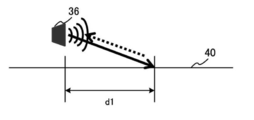
- the control unit 10 determines from the ultrasonic sensor 36 to the obstacle based on the time from the transmission wave transmission to the reception of the reflected wave. The distance is calculated. Then, the control unit 10 determines whether or not the calculated distance matches the predetermined distance (step S180).
- the predetermined distance is a distance d1 calculated by a preliminary experiment using the ultrasonic sensor 36 as shown in FIG. 5A when the ultrasonic sensor 36 is in a normal state under a predetermined environmental condition. It is.
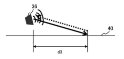
- step S220 determines that the attachment state of the ultrasonic sensor 36 is abnormal (step S220). For example, as shown in FIG. 5B, since the ultrasonic sensor 36 is attached to the vehicle 1 while being inclined toward the road surface, a situation is assumed in which the calculated distance d2 is shorter than the predetermined distance d1. Alternatively, as illustrated in FIG. 5C, since the ultrasonic sensor 36 is attached to the vehicle 1 while being inclined toward the sky, it is assumed that the calculated distance d3 is longer than the predetermined distance d1.
- step S180 when the calculated distance matches the predetermined distance (step S180, YES), the control unit 10 determines that the ultrasonic sensor 36 is attached normally (step S200). When the process of step S200 is completed, the ultrasonic distance measurement ECU 5 ends the process in FIG.
- the ultrasonic distance measurement ECU 5 includes a distance measurement unit (control unit 10) and a determination unit (control unit 10).
- the distance measuring unit (control unit 10) is attached to the vehicle 1, transmits a transmission wave toward the road surface 40, and reflects the transmission wave transmitted by the ultrasonic sensor 36 that receives the reflected wave reflected by the road surface 40. The distance to the road surface 40 is measured based on the time until the wave is received.
- the determination unit (control unit 10) determines that the attachment state of the ultrasonic sensor 36 is normal when the distance measured by the distance measurement unit matches the predetermined distance d1, while the distance measured by the distance measurement unit. Is not equal to the predetermined distance d1, it is determined that the attachment state of the ultrasonic sensor 36 is abnormal.
- both the transmission gain of the transmission wave transmitted from the ultrasonic sensor 36 and the reception gain of the reflected wave received by the ultrasonic sensor 36 are both.
- the present invention is not limited to this.
- only one of the transmission gain of the transmission wave transmitted from the ultrasonic sensor 36 and the reception gain of the reflected wave received by the ultrasonic sensor 36 is larger than that in the normal mode. May be set.
- both the transmission gain of the transmission wave transmitted from the ultrasonic sensor 36 and the reception gain of the reflected wave received by the ultrasonic sensor 36 are both obtained.
- the present invention is not limited to this.
- only one of the transmission gain of the transmission wave transmitted from the ultrasonic sensor 36 and the reception gain of the reflected wave received by the ultrasonic sensor 36 is the same as in normal time. It may be set to.
- the ultrasonic sensor 36 is not limited to the rear portion of the vehicle 1, and may be attached to the front portion or the side portion of the vehicle 1.
- the ultrasonic sensor 36 is not limited to the rear portion of the vehicle 1 when there is no obstacle around the vehicle according to the all-around camera image. Even if it is attached to the front part or the side part of the vehicle 1, it is possible to determine whether or not the attachment state of the ultrasonic sensor 36 is normal.
- the ultrasonic sensor 36 having both a function of transmitting a transmission wave and a function of receiving a reflected wave reflected by an obstacle is attached to the rear portion of the vehicle 1.
- the invention is not limited to this.
- an ultrasonic sensor having only a function of transmitting a transmission wave and an ultrasonic sensor having only a function of receiving a reflected wave may be attached to the rear portion of the vehicle 1.
- the present invention is useful as a sensor attachment state determination device and a sensor attachment state determination method that can determine whether or not the attachment state of an ultrasonic sensor is normal without actually confirming by the driver.
Landscapes
- Engineering & Computer Science (AREA)
- Radar, Positioning & Navigation (AREA)
- Remote Sensing (AREA)
- Physics & Mathematics (AREA)
- Computer Networks & Wireless Communication (AREA)
- General Physics & Mathematics (AREA)
- Acoustics & Sound (AREA)
- Measurement Of Velocity Or Position Using Acoustic Or Ultrasonic Waves (AREA)
Abstract
La présente invention concerne un dispositif de détermination d'état de montage de capteur qui comprend une unité de mesure de distance qui mesure la distance d'un véhicule à la surface de route en fonction du temps requis pour qu'un capteur à ultrasons transmette une onde de transmission et reçoive une onde réfléchie, ledit capteur à ultrasons étant monté sur le véhicule et étant utilisé pour transmettre l'onde de transmission vers la surface de route et pour recevoir l'onde réfléchie qui est réfléchie en retour vers la surface de route. En outre, le dispositif est pourvu d'une unité de détermination par laquelle, si la distance mesurée par l'unité de mesure de distance correspond à une distance prédéterminée, l'état de montage de capteur à ultrasons est déterminé comme étant normal, alors que, si la distance mesurée par l'unité de mesure de distance ne correspond pas à la distance prédéterminée, l'état de montage de capteur à ultrasons est déterminé comme étant anormal.
Priority Applications (1)
| Application Number | Priority Date | Filing Date | Title |
|---|---|---|---|
| US16/131,928 US10571553B2 (en) | 2016-03-18 | 2018-09-14 | Sensor mounting state determination device and sensor mounting state determination method |
Applications Claiming Priority (2)
| Application Number | Priority Date | Filing Date | Title |
|---|---|---|---|
| JP2016055134A JP2017167096A (ja) | 2016-03-18 | 2016-03-18 | 取り付け状態判定装置および取り付け状態判定方法 |
| JP2016-055134 | 2016-03-18 |
Related Child Applications (1)
| Application Number | Title | Priority Date | Filing Date |
|---|---|---|---|
| US16/131,928 Continuation US10571553B2 (en) | 2016-03-18 | 2018-09-14 | Sensor mounting state determination device and sensor mounting state determination method |
Publications (1)
| Publication Number | Publication Date |
|---|---|
| WO2017159170A1 true WO2017159170A1 (fr) | 2017-09-21 |
Family
ID=59851820
Family Applications (1)
| Application Number | Title | Priority Date | Filing Date |
|---|---|---|---|
| PCT/JP2017/005215 Ceased WO2017159170A1 (fr) | 2016-03-18 | 2017-02-14 | Dispositif de détermination d'état de montage de capteur et procédé de détermination d'état de montage de capteur |
Country Status (3)
| Country | Link |
|---|---|
| US (1) | US10571553B2 (fr) |
| JP (1) | JP2017167096A (fr) |
| WO (1) | WO2017159170A1 (fr) |
Families Citing this family (3)
| Publication number | Priority date | Publication date | Assignee | Title |
|---|---|---|---|---|
| DE102018124024A1 (de) * | 2018-09-28 | 2020-04-02 | Valeo Schalter Und Sensoren Gmbh | Verfahren zum Betreiben eines Ultraschallsensors eines Fahrzeugs mit reduzierter Diagnose in einem Messbetrieb des Ultraschallsensors sowie Ultraschallsensorvorrichtung |
| CN117480407A (zh) * | 2021-07-06 | 2024-01-30 | 株式会社爱信 | 物体检测装置 |
| DE102024208186A1 (de) | 2024-08-28 | 2026-03-05 | Robert Bosch Gesellschaft mit beschränkter Haftung | Verfahren zum Kalibrieren eines Ultraschallsensors eines ultraschallbasierten Fahrerassistenzsystems eines Fahrzeugs und Fahrzeug |
Citations (8)
| Publication number | Priority date | Publication date | Assignee | Title |
|---|---|---|---|---|
| JPS57175266A (en) * | 1981-04-21 | 1982-10-28 | Nippon Denso Co Ltd | Obstacle detector for car |
| JPS6180471U (fr) * | 1984-09-29 | 1986-05-28 | ||
| JPH02196988A (ja) * | 1989-01-26 | 1990-08-03 | Matsushita Electric Works Ltd | 車両用超音波検知装置 |
| US5235315A (en) * | 1992-01-02 | 1993-08-10 | Armatron International, Inc. | Self test for obstacle detection system |
| JPH08292257A (ja) * | 1995-04-25 | 1996-11-05 | Matsushita Electric Works Ltd | 超音波センサ |
| JP2010286417A (ja) * | 2009-06-15 | 2010-12-24 | Clarion Co Ltd | 超音波センサの車体への取付け角度計測方法及びその計測システム |
| US20120275263A1 (en) * | 2009-11-30 | 2012-11-01 | Florian Kloss | Method for adjusting the sensitivity of ultrasonic sensors |
| WO2015118804A1 (fr) * | 2014-02-05 | 2015-08-13 | パナソニックIpマネジメント株式会社 | Dispositif de détection d'objet |
Family Cites Families (7)
| Publication number | Priority date | Publication date | Assignee | Title |
|---|---|---|---|---|
| JPS5826283A (ja) | 1981-08-07 | 1983-02-16 | Yokogawa Hokushin Electric Corp | 自己診断機能を持つ超音波測定装置 |
| JPS58216972A (ja) | 1982-06-11 | 1983-12-16 | Aisin Seiki Co Ltd | 反射型物体検出装置 |
| US4542489A (en) | 1982-05-18 | 1985-09-17 | Aisin Seiki Kabushiki Kaisha | Object detecting system of reflection type |
| US7663502B2 (en) * | 1992-05-05 | 2010-02-16 | Intelligent Technologies International, Inc. | Asset system control arrangement and method |
| US7164117B2 (en) * | 1992-05-05 | 2007-01-16 | Automotive Technologies International, Inc. | Vehicular restraint system control system and method using multiple optical imagers |
| JPH09178837A (ja) | 1995-12-22 | 1997-07-11 | Pacific Ind Co Ltd | 障害物検知装置 |
| JP3054798U (ja) | 1998-06-09 | 1998-12-18 | 森利 陳 | 五層式組合せブロック知育玩具 |
-
2016
- 2016-03-18 JP JP2016055134A patent/JP2017167096A/ja active Pending
-
2017
- 2017-02-14 WO PCT/JP2017/005215 patent/WO2017159170A1/fr not_active Ceased
-
2018
- 2018-09-14 US US16/131,928 patent/US10571553B2/en active Active
Patent Citations (8)
| Publication number | Priority date | Publication date | Assignee | Title |
|---|---|---|---|---|
| JPS57175266A (en) * | 1981-04-21 | 1982-10-28 | Nippon Denso Co Ltd | Obstacle detector for car |
| JPS6180471U (fr) * | 1984-09-29 | 1986-05-28 | ||
| JPH02196988A (ja) * | 1989-01-26 | 1990-08-03 | Matsushita Electric Works Ltd | 車両用超音波検知装置 |
| US5235315A (en) * | 1992-01-02 | 1993-08-10 | Armatron International, Inc. | Self test for obstacle detection system |
| JPH08292257A (ja) * | 1995-04-25 | 1996-11-05 | Matsushita Electric Works Ltd | 超音波センサ |
| JP2010286417A (ja) * | 2009-06-15 | 2010-12-24 | Clarion Co Ltd | 超音波センサの車体への取付け角度計測方法及びその計測システム |
| US20120275263A1 (en) * | 2009-11-30 | 2012-11-01 | Florian Kloss | Method for adjusting the sensitivity of ultrasonic sensors |
| WO2015118804A1 (fr) * | 2014-02-05 | 2015-08-13 | パナソニックIpマネジメント株式会社 | Dispositif de détection d'objet |
Also Published As
| Publication number | Publication date |
|---|---|
| JP2017167096A (ja) | 2017-09-21 |
| US10571553B2 (en) | 2020-02-25 |
| US20190018122A1 (en) | 2019-01-17 |
Similar Documents
| Publication | Publication Date | Title |
|---|---|---|
| JP4873651B2 (ja) | 自動車用の装置及び方法 | |
| US9121920B2 (en) | Method for operating at least one sensor of a vehicle and vehicle having at least one sensor | |
| US5531118A (en) | Method and device for operating an ultrasonic sensor | |
| CN111076743A (zh) | 利用其他车辆的车辆传感器现场校准 | |
| JP6445419B2 (ja) | 物体検出装置、及び物体検出方法 | |
| CN107735693B (zh) | 驾驶辅助装置以及驾驶辅助方法 | |
| JP6073646B2 (ja) | 補正値設定装置、および距離検出装置 | |
| CN110998685B (zh) | 行进障碍检测装置和车辆导航系统 | |
| KR20170046696A (ko) | 주변 물체의 존재에 관한 자동차 운전자의 경고 방법, 운전자 보조 시스템 및 자동차 | |
| WO2016063535A1 (fr) | Appareil d'avertissement d'obstacle | |
| WO2020230253A1 (fr) | Système de détection d'objet monté sur un véhicule | |
| JP6289546B2 (ja) | 駐車支援装置 | |
| JP2006240453A (ja) | センサ異常検出装置及びセンサ異常検出方法 | |
| WO2017159170A1 (fr) | Dispositif de détermination d'état de montage de capteur et procédé de détermination d'état de montage de capteur | |
| JP6320880B2 (ja) | 検知システム | |
| WO2019151156A1 (fr) | Dispositif de détection d'objet et dispositif d'aide au stationnement | |
| CN114690132A (zh) | 车载雷达的标定方法、装置、存储介质及车辆 | |
| JP7099354B2 (ja) | 運転支援装置 | |
| CN109952517A (zh) | 物体检测传感器的轴偏离判定方法 | |
| JP2016191614A (ja) | 障害物検出装置、湿度補正値算出方法、および超音波受波しきい値決定方法 | |
| JP7192647B2 (ja) | 付着検知装置および付着検知方法 | |
| JP2017167094A (ja) | 動作判定装置および動作判定方法 | |
| JP2859928B2 (ja) | 車両用後方監視装置 | |
| KR20250058154A (ko) | 휠 얼라인먼트 이상 검출 장치 및 방법 | |
| JP2005343426A (ja) | 障害物検出装置 |
Legal Events
| Date | Code | Title | Description |
|---|---|---|---|
| NENP | Non-entry into the national phase |
Ref country code: DE |
|
| 121 | Ep: the epo has been informed by wipo that ep was designated in this application |
Ref document number: 17766177 Country of ref document: EP Kind code of ref document: A1 |
|
| 122 | Ep: pct application non-entry in european phase |
Ref document number: 17766177 Country of ref document: EP Kind code of ref document: A1 |