WO2017159225A1 - Dispositif d'examen de fatigue oculaire et procédé d'examen de fatigue oculaire - Google Patents
Dispositif d'examen de fatigue oculaire et procédé d'examen de fatigue oculaire Download PDFInfo
- Publication number
- WO2017159225A1 WO2017159225A1 PCT/JP2017/006177 JP2017006177W WO2017159225A1 WO 2017159225 A1 WO2017159225 A1 WO 2017159225A1 JP 2017006177 W JP2017006177 W JP 2017006177W WO 2017159225 A1 WO2017159225 A1 WO 2017159225A1
- Authority
- WO
- WIPO (PCT)
- Prior art keywords
- eye
- light amount
- light
- amount difference
- examined
- Prior art date
- Legal status (The legal status is an assumption and is not a legal conclusion. Google has not performed a legal analysis and makes no representation as to the accuracy of the status listed.)
- Ceased
Links
Images







Classifications
-
- A—HUMAN NECESSITIES
- A61—MEDICAL OR VETERINARY SCIENCE; HYGIENE
- A61B—DIAGNOSIS; SURGERY; IDENTIFICATION
- A61B3/00—Apparatus for testing the eyes; Instruments for examining the eyes
- A61B3/10—Objective types, i.e. instruments for examining the eyes independent of the patients' perceptions or reactions
- A61B3/113—Objective types, i.e. instruments for examining the eyes independent of the patients' perceptions or reactions for determining or recording eye movement
-
- A—HUMAN NECESSITIES
- A61—MEDICAL OR VETERINARY SCIENCE; HYGIENE
- A61B—DIAGNOSIS; SURGERY; IDENTIFICATION
- A61B3/00—Apparatus for testing the eyes; Instruments for examining the eyes
- A61B3/0008—Apparatus for testing the eyes; Instruments for examining the eyes provided with illuminating means
-
- A—HUMAN NECESSITIES
- A61—MEDICAL OR VETERINARY SCIENCE; HYGIENE
- A61B—DIAGNOSIS; SURGERY; IDENTIFICATION
- A61B3/00—Apparatus for testing the eyes; Instruments for examining the eyes
- A61B3/0016—Operational features thereof
-
- A—HUMAN NECESSITIES
- A61—MEDICAL OR VETERINARY SCIENCE; HYGIENE
- A61B—DIAGNOSIS; SURGERY; IDENTIFICATION
- A61B3/00—Apparatus for testing the eyes; Instruments for examining the eyes
- A61B3/02—Subjective types, i.e. testing apparatus requiring the active assistance of the patient
- A61B3/08—Subjective types, i.e. testing apparatus requiring the active assistance of the patient for testing binocular or stereoscopic vision, e.g. strabismus
-
- A—HUMAN NECESSITIES
- A61—MEDICAL OR VETERINARY SCIENCE; HYGIENE
- A61B—DIAGNOSIS; SURGERY; IDENTIFICATION
- A61B3/00—Apparatus for testing the eyes; Instruments for examining the eyes
- A61B3/10—Objective types, i.e. instruments for examining the eyes independent of the patients' perceptions or reactions
Definitions
- the present invention relates to an eye fatigue inspection apparatus and an eye fatigue inspection method for objectively inspecting eye fatigue of an eye to be examined.
- VDT Visual Display Terminal
- CVS computer vision syndrome
- Patent Document 1 a target is placed at the farthest farthest position where the subject's eye can be clearly seen based on the result of measuring the refractive power of the subject's eye by visually observing the target that is unique to the subject's eye.
- An eye accommodation function measuring device that measures the accommodation function state of an eye to be examined who is viewing a visual target is described.
- frequency variation of refractive power with time is analyzed as an index indicating the accommodation function state of the eye to be examined, and the appearance frequency of a predetermined high frequency component is calculated. Since there is a close relationship between the accommodation function state of the eye to be examined and eye fatigue, the eye fatigue of the eye to be examined can be objectively examined using the eye accommodation function measuring device of Patent Document 1.
- the eye accommodation function measuring device of Patent Document 1 examines eye fatigue of the eye to be examined. I can't. As a result, there is a problem that middle-aged and elderly people who are the generation with the largest population in an aging society cannot be examined for eye fatigue, and middle-aged and elderly people cannot receive appropriate diagnosis and treatment.
- the present invention has been made in view of such circumstances, and an object thereof is to provide an eye fatigue inspection device and an eye fatigue inspection method that can inspect eye fatigue of an eye to be examined regardless of the age of the patient. .
- An eye fatigue inspection device for achieving the object of the present invention is a light amount difference adjustment unit that expands a light amount difference between light incident on the left and right eyes, and a light amount difference adjustment unit while expanding the light amount difference.
- a line-of-sight direction detection unit that detects the line-of-sight direction of the eye to be examined, and a light amount difference determination unit that determines a specific light amount difference that causes a change in the line-of-sight direction due to an increase in the light amount difference based on the detection result of the line-of-sight direction detection unit; Is provided.
- the “eye fatigue” referred to in the present specification includes so-called “eye fatigue”.
- the eye fatigue of the eye to be examined can be objectively examined (evaluated) based on the patient's fusion power, so the eye fatigue of the eye to be examined is examined regardless of the age of the patient. It is possible to examine eye fatigue of middle-aged and elderly people, which has been untouched conventionally. As a result, an objective test useful for diagnosis and treatment of CVS becomes possible.
- the eye fatigue inspection apparatus includes an output unit that outputs a specific light amount difference determined by the light amount difference determination unit as an index of eye fatigue of the eye to be examined. Thereby, a doctor can diagnose and evaluate eye fatigue of the eye to be examined.
- the eye fatigue inspection apparatus includes an index display unit that displays an inspection target visually observed by the eye to be examined, and the light amount difference determination unit is based on the detection result of the line-of-sight direction detection unit, A specific light amount difference is determined by determining the presence or absence of a change in the line-of-sight direction from the state in which the eye to be examined is viewing the inspection target. Thereby, the light amount difference at the time when the destruction of the fusion caused by the increase in the transmittance difference can be determined as the specific light amount difference.
- the gaze direction detection unit detects the position of the Purkinje image of the eye to be examined or the position of the pupil of the eye to be examined, and the light amount difference determination unit has the eye to be examined.
- a specific light amount difference is determined by determining the presence or absence of a change in the Purkinje image or the position of the pupil from the state where the inspection target is viewed. Thereby, the light amount difference at the time when the destruction of the fusion caused by the increase in the transmittance difference can be determined as the specific light amount difference.
- the light amount difference adjustment unit reduces the amount of light incident on one of the eyes to be examined and maintains the amount of light incident on the other of the eyes to be constant. As a result, the light quantity difference is increased. Thereby, since the change of the gaze direction accompanying the destruction of the fusion can be generated, the strength of the fusion power of the eye to be examined can be evaluated.
- the light amount difference adjustment unit has a transmission region capable of adjusting the transmittance of light incident on at least one of the eyes to be examined, and the transmittance of the transmission region is adjusted.
- the light quantity difference is enlarged by adjusting.
- the specific light amount determined by the light amount difference determination unit is expressed as the difference in transmittance between the two transmissive regions.
- the light amount difference adjusting unit expands the light amount difference continuously or stepwise. Thereby, a change in the line-of-sight direction accompanying the destruction of the fusion image can be generated.
- the light incident on the eye to be examined includes light in a first wavelength range and light in a second wavelength range different from the first wavelength range, and is applied to the eye to be examined.
- a dichroic mirror that transmits light in the first wavelength range and reflects light in the second wavelength range reflected by the eye to the side of the optical path in the optical path of the reflected light. Detects the line-of-sight direction based on the result of detecting the light in the second wavelength range reflected by the dichroic mirror.
- An eye fatigue inspection method for achieving the object of the present invention includes a light amount difference adjustment step for expanding a light amount difference between light incident on the left and right eyes, and a light amount difference adjustment step for expanding the light amount difference.
- a gaze direction detecting step for detecting a gaze direction of the eye to be examined, and a light amount difference determining step for determining a specific light amount difference that causes a change in the gaze direction due to an increase in the light amount difference based on a detection result of the gaze direction detecting step.
- the eye fatigue inspection method includes an output step of outputting the specific light amount difference determined in the light amount difference determination step as an index of eye fatigue of the eye to be examined.
- the eye fatigue inspection method includes a target display step for displaying an inspection target visually observed by the eye to be examined.
- the detection result in the line-of-sight direction detection step is displayed. Based on this, a specific light amount difference is determined by determining whether or not there is a change in the line-of-sight direction from the state in which the eye to be examined is viewing the inspection target.
- the gaze direction detection step the position of the Purkinje image of the eye to be examined or the position of the pupil of the eye to be examined is detected, and in the light amount difference determination step, the eye to be examined is for examination.
- a specific light amount difference is determined by determining the presence or absence of a change in the Purkinje image or the position of the pupil from a state in which the target is viewed.
- the amount of light incident on one of the eyes to be examined is reduced, and the amount of light incident on the other of the eyes to be examined is maintained constant. As a result, the light quantity difference is increased.
- a transmission region capable of adjusting the light transmittance is disposed in the optical path of light incident on at least one of the eyes to be examined.
- the light amount difference is enlarged by adjusting the transmittance of the region.
- the specific light amount difference determined in the light amount difference determining step is two transmissions. Expressed as the difference in transmittance of the area.
- the light amount difference adjustment step expands the light amount difference continuously or stepwise.
- the light incident on the eye to be examined includes light in a first wavelength range and light in a second wavelength range different from the first wavelength range.
- the dichroic mirror that transmits the light in the first wavelength range and reflects the light in the second wavelength range reflected by the eye to the side of the optical path is disposed in the optical path of the reflected light to detect the direction of the line of sight
- the line-of-sight direction is detected based on the result of detecting the light in the second wavelength range reflected by the dichroic mirror.
- eye fatigue of the eye to be examined can be inspected regardless of the age of the patient.
- FIG. 1 is a schematic top view of an eye fatigue inspection apparatus 10 that objectively inspects eye fatigue of the left and right eyes 9R and 9L of a patient based on the strength of the patient's fusion (fusion power).
- fusion is a function that fuses the retina images of both eyes and recognizes them as one image.
- illustration is abbreviate
- the eye fatigue inspection device 10 includes an optometry table 11, a pair of infrared light sources 12R and 12L, a target display unit 13, a pair of dichroic mirrors 14R and 14L, and a pair of liquid crystal shutters 15R, 15L, a pair of measurement units 16R and 16L, and an inspection apparatus main body 17 are provided.
- each part of the eye fatigue inspection device 10 excluding the inspection device body 17 is arranged. Further, a face receiving portion (not shown) is arranged at the front end portion (lower end portion in the drawing) located on the patient side of the optometry table 11. When the patient places his chin on the face receiving portion and applies a forehead, the positions of the eyes 9R and 9L on the optometry table 11 are determined.
- the infrared light sources 12R and 12L are attached to the face receiving portion (not shown).
- the infrared light source 12R is attached in the vicinity of the subject eye 9R, and irradiates the subject eye 9R with near infrared light.
- the infrared light source 12L is attached in the vicinity of the eye 9L, and irradiates near-infrared light to the eye 9L.
- the wavelength range of the near infrared light irradiated by the infrared light sources 12R and 12L is, for example, a wavelength of 950 nm.
- the optotype display unit 13 is disposed at the rear end portion on the opposite side of the front end portion of the optometry table 11 so as to be positioned in the front direction of the subject eyes 9R and 9L.
- the target display unit 13 can be moved and adjusted in the front-rear direction to approach the eyes 9R and 9L or to move away from the eyes 9R and 9L by a slide mechanism (not shown). Thereby, the target display unit 13 can be moved to a distance (for example, 30 cm, 50 cm, 1 m) that is easy for the subject eyes 9R, 9L to visually recognize according to the refractive power of the subject eyes 9R, 9L.
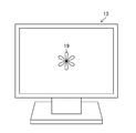
- FIG. 2 is a front view of the visual target display unit 13 viewed from the side of the eye to be examined 9R, 9L.
- the optotype display unit 13 displays an inspection target 19 that is visually observed by the eyes 9R and 9L during the eye fatigue inspection.
- a display method of the inspection target 19 by the target display unit 13 a method of displaying an image of the inspection target 19 on a liquid crystal monitor or the like, or a sheet on which an image of the inspection target 19 is printed is pasted.
- Various methods such as a method of attaching can be adopted.
- the dichroic mirror 14R is disposed on the optical path 21R (on the line of sight of the eye 9R to be examined) connecting the inspection target 19 and the eye 9R to be examined.
- the dichroic mirror 14L is disposed on an optical path 21L (on the line of sight of the eye 9L to be examined) connecting the inspection target 19 and the eye 9L to be examined.
- the dichroic mirrors 14 ⁇ / b> R and 14 ⁇ / b> L can be rotationally adjusted around an axis perpendicular to the upper surface of the optometry table 11.
- the dichroic mirror 14R is disposed on the optical path 21R in a state inclined by 45 ° with respect to the optical path 21R, and the dichroic mirror 14L is disposed on the optical path 21L in a state inclined by 45 ° with respect to the optical path 21L.
- the dichroic mirrors 14R and 14L transmit visible light (wavelength range: about 380 nm to 780 nm) corresponding to light in the first wavelength range of the present invention, and light in other wavelength ranges, for example, in the second wavelength range of the present invention.
- Near infrared light corresponding to light (wavelength range: about 800 nm to 2500 nm) is reflected. Thereby, the test target 19 can be visually observed (natural vision) with the eyes 9R and 9L.
- the near infrared light traveling along the optical path 21R in the near infrared light reflected by the eye 9R is reflected toward the right side of the optical path 21R by the dichroic mirror 14R.
- near infrared light traveling along the optical path 21L in the near infrared light reflected by the eye 9L is reflected toward the left side of the optical path 21L by the dichroic mirror 14L.
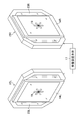
- FIG. 3 is a front view of the liquid crystal shutters 15R and 15L viewed from the patient side.
- the liquid crystal shutters 15R and 15L function as a part of the light amount difference adjustment unit of the present invention.
- the liquid crystal shutter 15R is mounted on the surface of the dichroic mirror 14R on the target display unit 13 side
- the liquid crystal shutter 15L is mounted on the surface of the dichroic mirror 14L on the target display unit 13 side.
- the liquid crystal shutters 15R and 15L are disposed in the optical paths 21R and 21L, respectively. Accordingly, the subject eye 9R views the inspection target 19 through the dichroic mirror 14R and the liquid crystal shutter 15R, and the subject eye 9L views the inspection target 19 through the dichroic mirror 14L and the liquid crystal shutter 15L.
- the positions of the liquid crystal shutters 15R and 15L are not particularly limited as long as they are arranged on the optical paths 21R and 21L, respectively.
- the liquid crystal shutters 15R and 15L include the dichroic mirrors 14R and 14L and the target display unit. 13 is preferable.
- the liquid crystal shutters 15R and 15L have transmission regions 23R and 23L (see FIG. 3) through which light (visible light) traveling along the optical paths 21R and 21L is transmitted.
- the liquid crystal shutters 15R and 15L can arbitrarily adjust the transmittance of light transmitted through the transmission regions 23R and 23L by arbitrarily changing the density of the transmission regions 23R and 23L. Thereby, the brightness
- X-FOS (G2) -CE manufactured by LC-Tec Holding AB
- the measured liquid crystal transmittance of the liquid crystal shutters 15R and 15L is 23.0% at the maximum and 0.07% at the minimum when measured with a spectroradiometer SR-LEDW manufactured by Topcon Corporation.
- the delay time (response time) of the liquid crystal shutters 15R and 15L is 2.5 ms or less.
- the measurement unit 16R is arranged on the right side of the dichroic mirror 14R, and the measurement unit 16L is arranged on the left side of the dichroic mirror 14L.
- the measurement units 16R and 16L can be rotated and adjusted around an axis perpendicular to the upper surface of the optometry table 11.
- the measurement units 16R and 16L emit near infrared light (wavelength 840 nm) having a wavelength range different from that of the infrared light sources 12R and 12L to the dichroic mirrors 14R and 14L, respectively.
- the near-infrared light having a wavelength of 840 nm is reflected by the dichroic mirrors 14R and 14L toward the subject's eyes 9R and 9L.
- near-infrared light of two wavelengths (wavelengths 950 nm and 840 nm) is incident on the eye to be examined 9R and 9L.
- the two-wavelength near-infrared light reflected by the subject eyes 9R and 9L passes through the optical paths 21R and 21L and enters the dichroic mirrors 14R and 14L, and the dichroic mirrors 14R and 14L enter the measurement units 16R and 16L. Each is reflected toward.
- the measurement units 16R and 16L constitute a part of the line-of-sight direction detection unit of the present invention, and receive two wavelengths of near-infrared light reflected by the dichroic mirrors 14R and 14L, respectively. Are respectively output to the inspection apparatus main body 17.
- the measurement units 16R and 16L receive near-infrared light with a wavelength of 950 nm and receive a near-infrared light with a wavelength of 840 nm and an anterior ocular segment observation system 25 that outputs a light-receiving signal used for detection of the line-of-sight direction.
- an aberration measurement system 26 that outputs a received light signal used to detect the focus position (wavefront aberration) of the eyes 9R and 9L (see FIG. 4).
- near-infrared light having two wavelengths reflected by the dichroic mirrors 14R and 14L is used as measurement light for detecting the line-of-sight direction and the focus position of the eyes 9R and 9L.
- FIG. 4 is a block diagram showing the configuration of the measurement unit 16R.
- the measurement unit 16R includes an objective lens 30, a dichroic mirror 31, and a mirror 32 in addition to the anterior ocular segment observation system 25 and the aberration measurement system 26 described above.
- the objective lens 30 emits near-infrared light having a wavelength of 840 nm that is incident through an aberration measurement system 26, a mirror 32, and a dichroic mirror 31, which will be described later, toward the dichroic mirror 14R. Further, near-infrared light of two wavelengths (wavelength 840 nm, wavelength 950 nm) is incident on the objective lens 30 from the eye 9R through the optical path 21R and the dichroic mirror 14R. The objective lens 30 emits near-infrared light having two wavelengths incident from the dichroic mirror 14 ⁇ / b> R toward the dichroic mirror 31.
- the dichroic mirror 31 transmits near infrared light with a wavelength of 950 nm and reflects near infrared light with a wavelength of 840 nm. Accordingly, the dichroic mirror 31 reflects near-infrared light having a wavelength of 840 nm incident from the aberration measurement system 26 via the mirror 32 toward the objective lens 30. Further, the dichroic mirror 31 causes near-infrared light having a wavelength of 950 nm to be incident on the anterior ocular segment observation system 25 out of the two wavelengths of near-infrared light incident from the objective lens 30, and the near-infrared light having a wavelength of 840 nm is mirrored. Reflects toward 32.
- the mirror 32 reflects near-infrared light having a wavelength of 840 nm incident from one of the aberration measurement system 26 and the dichroic mirror 31 toward the other.
- the anterior ocular segment observation system 25 includes a relay lens 35, an imaging lens 36, and a CCD (Charge-Coupled Device) type or CMOS (Complementary Metal Oxide Semiconductor) type imaging device 37.
- the relay lens 35 emits near-infrared light having a wavelength of 950 nm incident from the dichroic mirror 31 toward the imaging lens 36.
- the imaging lens 36 images near-infrared light having a wavelength of 950 nm incident from the relay lens 35 on the light receiving surface of the image sensor 37.
- the image sensor 37 receives (images) near-infrared light having a wavelength of 950 nm formed by the imaging lens 36 and outputs a received light signal indicating an anterior eye image of the eye 9R to be examined to the inspection apparatus body 17. .
- a binocular wavefront sensor is used for the aberration measurement system 26.
- the aberration measurement system 26 includes a semiconductor element 40 such as SDL (Super luminescent diode), a collimating lens 41, a beam splitter 42, a mirror 43, an imaging lens 44, a Hartmann plate 45, a CCD type or a CMOS type. Imaging device 46.
- the semiconductor element 40 emits near-infrared light having a wavelength of 840 nm toward the collimating lens 41.
- the collimator lens 41 converts near-infrared light having a wavelength of 840 nm incident from the semiconductor element 40 into parallel light, and then emits the light toward the beam splitter 42.
- the beam splitter 42 reflects near-infrared light having a wavelength of 840 nm incident from the collimator lens 41 toward the mirror 32. Further, the beam splitter 42 transmits the near-infrared light having a wavelength of 840 nm incident from the mirror 32 through the dichroic mirror 31 or the like as it is and enters the mirror 43.
- the mirror 43 reflects near-infrared light having a wavelength of 840 nm incident from the beam splitter 42 toward the imaging lens 44.
- the imaging lens 44 images near-infrared light having a wavelength of 840 nm incident from the mirror 43 on the Hartmann plate 45.
- the Hartmann plate 45 divides near-infrared light having a wavelength of 840 nm incident from the imaging lens 44 into a plurality of light beams corresponding to each microlens, and forms each light beam on the light receiving surface of the image sensor 46.
- the image sensor 46 receives (images) a plurality of light beams imaged on the light receiving surface by the Hartmann plate 45 and outputs a light reception signal indicating a plurality of point images corresponding to each light beam to the inspection apparatus main body 17.
- the measurement unit 16L Since the measurement unit 16L has the same configuration as the measurement unit 16R, description and illustration of each part of the measurement unit 16L will be omitted.
- the measurement unit 16L receives near-infrared light having a wavelength of 950 nm reflected by the eye to be examined 9L by the anterior eye portion observation system 25, and receives a light reception signal indicating an image of the anterior eye portion of the eye to be examined 9L. Output to.
- the measurement unit 16L receives near-infrared light having a wavelength of 840 nm reflected by the eye 9L to be received by the aberration measurement system 26, and outputs received light signals indicating a plurality of point images to the inspection apparatus body 17.
- FIG. 5 is a block diagram showing the configuration of the inspection apparatus main body 17.
- this inspection apparatus main body 17 various arithmetic processing apparatuses, such as a personal computer, are used, for example.
- the inspection apparatus main body 17 includes a transmittance adjusting unit 50, a gaze direction detecting unit 51, a focus position detecting unit 52, a determining unit 53, a transmittance difference determining unit 54, and an output unit. 55, a display unit 56, and a storage unit 57.
- the configuration from the transmittance adjusting unit 50 to the output unit 55 is realized by, for example, a CPU (Central Processing Unit) or an FPGA (field-programmable gate array).
- the transmittance adjusting unit 50 constitutes a light amount difference adjusting unit of the present invention together with the liquid crystal shutters 15R and 15L described above, and adjusts the transmittance (density) of the transmission regions 23R and 23L of the liquid crystal shutters 15R and 15L.
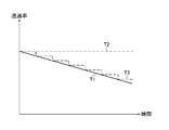
- FIG. 6 is an explanatory diagram for explaining the transmittance adjustment of the transmission regions 23R and 23L of the liquid crystal shutters 15R and 15L.
- the transmittance adjustment unit 50 has a transmittance corresponding to one of the transmission regions 23R, 23L as indicated by a straight line T1.
- the transmittance continuously decreases with time, and the transmittance corresponding to the other of the transmission regions 23R and 23L is maintained constant (for example, maximum transmittance) as indicated by a straight line T2.
- the amount of visible light incident on one of the subject's eyes 9R and 9L is continuously reduced over time, and the amount of visible light incident on the other of the subject's eyes 9R and 9L is maintained constant.
- the transmittance difference that is the difference between the transmittances of the transmission regions 23R and 23L increases with the passage of time, so the difference in light amount that is the difference in the amount of visible light incident on each of the eyes 9R and 9L increases. To do.
- the amount of visible light incident on the non-dominant eye on the opposite side of the patient's dominant eye (dominant eye) from the eye to be examined 9R, 9L is continuously reduced over time.
- the transmittance corresponding to one of the transmission regions 23R and 23L is continuously decreased with the passage of time. However, even if this transmittance is decreased stepwise as indicated by a broken line T3. Good. Thereby, the light quantity of visible light which injects into one of the to-be-tested eyes 9R and 9L reduces in steps with progress of time.
- the line-of-sight direction detection unit 51 constitutes the line-of-sight direction detection unit of the present invention together with the measurement units 16R and 16L described above.
- the line-of-sight direction detection unit 51 receives the light reception signals input from the image sensors 37 of the measurement units 16R and 16L while the transmittance adjustment unit 50 enlarges the transmittance difference (light amount difference) between the transmission regions 23R and 23L. Based on the above, the line-of-sight directions of the eyes 9R and 9L are detected.
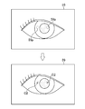
- FIG. 7 is an explanatory diagram for explaining an example of gaze direction detection using an image measurement method (dark pupil method).
- the line-of-sight direction detection unit 51 shows the anterior eye part indicating the anterior eye part of the eyes 9R and 9L based on the light reception signals input from the imaging elements 37 of both the measurement units 16R and 16L.
- An image 59 (here, only the anterior segment image 59 of the eye 9R to be examined is shown) is generated.
- the line-of-sight direction detection unit 51 binarizes the anterior eye image 59 of the eyes 9R and 9L to be examined with a predetermined luminance threshold value. Since the pupils of the subject eyes 9R and 9L have lower luminance than the surrounding area, when the anterior eye image 59 is binarized, the area corresponding to the pupil in the anterior eye image 59 becomes a black pixel area. The area around the pupil is the white pixel area. Thereby, the pupil region of the eye 9R, 9L to be examined can be specified from the anterior eye image 59.
- the line-of-sight direction detection unit 51 obtains the center coordinates C1 of the pupil regions (black pixel regions) of the eyes 9R and 9L from the binarized anterior eye image 59, Based on the obtained center coordinates C1 and the known geometric structure of the eyeball, the line-of-sight directions of the eyes 9R and 9L to be examined are detected. Note that detection of the line-of-sight direction by the dark pupil method is a well-known technique, and a detailed description thereof will be omitted.
- the gaze direction is detected by the image measurement method
- the position of a spot image (xy spot) formed on the retina of the eye 9R, 9L is detected, or the Purkinje image 59p.
- the position of may be detected.
- FIG. 8 is an explanatory diagram for explaining an example of gaze direction detection using the Purkinje image 59p.
- a Purkinje image 59p which is a reflected image of near-infrared light, is generated on the cornea surfaces of the eyes 9R and 9L due to incidence of near-infrared light.
- the position of the Purkinje image 59p changes according to the change in the viewing direction of the eyes 9R and 9L. Therefore, the position of the Purkinje image 59p is information indicating the viewing direction of the eyes 9R and 9L.
- the line-of-sight direction detection unit 51 analyzes the anterior eye image 59 of the eyes 9R and 9L and detects the position coordinates C2 of the Purkinje image 59p from the anterior eye image 59. Then, the line-of-sight direction detection unit 51 detects the line-of-sight directions of the eyes 9R and 9L based on the relative position between the position of the Purkinje image 59p indicated by the position coordinates C2 and the center of the pupil. Note that the method for detecting the direction of the line of sight using the Purkinje image 59p is also a known technique, and a detailed description thereof will be omitted.
- the line-of-sight direction detection unit 51 detects the line-of-sight direction of the eyes 9R and 9L and determines the determination unit while the transmittance adjustment unit 50 increases the transmittance difference (light amount difference) between the transmission regions 23R and 23L.
- the detection result output to 53 is continuously performed.
- the line-of-sight direction of the eyes 9R and 9L is detected using the image measurement method, but the line-of-sight direction of the eyes 9R and 9L may be detected using other methods.
- an EOG (electro-electro-oculography) method that detects a gaze direction by measuring a myoelectric signal that changes with the movement of muscles around the eyeballs of the subject's eyes 9R and 9L, or a contact lens that incorporates a search coil.
- Various methods such as a search coil method for detecting the direction of the line of sight by attaching to the optometers 9R and 9L may be used.
- the focus position detection unit 52 is configured so that the image sensor 46 of both of the measurement units 16R and 16L is obtained while the transmittance adjustment unit 50 increases the transmittance difference (light amount difference) between the transmission regions 23R and 23L.
- the focus positions of the eyes 9R and 9L to be examined are detected on the basis of the light reception signal input from.
- the focus position detection unit 52 performs Zernike analysis or the like based on the received light signal input from the image sensor 46 to measure the wavefront aberration of the eyes 9R and 9L, and based on the measurement result of the wavefront aberration, the eyes 9R and 9L.
- the focus position (adjustment position) is detected. Note that a method for detecting the focus position by the wavefront aberration measurement process is a known technique, and thus detailed description thereof is omitted.
- the focus position detection unit 52 detects the focus position of the eyes 9R and 9L and determines the determination unit 53 while the transmittance adjustment unit 50 enlarges the transmittance difference (light amount difference) between the transmission regions 23R and 23L.
- the detection result is output continuously.
- the determination unit 53 changes the line-of-sight direction of the eyes 9R and 9L as the transmittance difference increases. To detect. More specifically, the determination unit 53 detects a change in the line-of-sight direction of the eyes 9R and 9L due to the destruction of the fusion caused by the increase in the transmittance difference.
- FIGS. 9A, 9B, and 9C are explanatory diagrams for explaining changes in the line-of-sight direction of the eyes 9R and 9L due to fusion destruction caused by an increase in the transmittance difference.
- FIG. 9A when the transmittance difference between the transmission regions 23R and 23L is zero (including almost zero), that is, the difference in the amount of visible light incident on the subject's eyes 9R and 9L is zero. In this case, a fusion is established in which the patient recognizes the image of the inspection target 19 viewed with the eyes 9R and 9L as one image.
- FIG. 9A when the transmittance difference between the transmission regions 23R and 23L is zero (including almost zero), that is, the difference in the amount of visible light incident on the subject's eyes 9R and 9L is zero. In this case, a fusion is established in which the patient recognizes the image of the inspection target 19 viewed with the eyes 9R and 9L as one image.
- FIG. 9A when the transmittance difference between the transmission regions 23R
- the patient has the test targets 19 that are visually observed by the eyes 9R and 9L, respectively. Since the image cannot be recognized as one image and the convergence is not maintained, the fusion is destroyed. As a result, a change occurs in the line-of-sight direction of the eye 9R.
- the present inventor has confirmed that there is a correlation between the eye fatigue of the eyes 9R and 9L to be examined and the strength of the patient's fusion power, specifically, the patient's fusion power decreases as the eye fatigue increases. did.
- the reduction of the fusion power of the patient means that the magnitude of the transmittance difference (light quantity difference) at which the fusion is destroyed decreases, that is, the fusion is destroyed at a low transmittance difference. Therefore, in the present embodiment, the determination unit 53 determines whether or not there is a change in the line-of-sight direction of the eyes 9R and 9L due to the increase in the transmittance difference.
- the determination unit 53 receives the gaze direction detection result input from the gaze direction detection unit 51 and the focus position detection unit 52 while the difference in transmittance between the transmission regions 23R and 23L is enlarged. Whether or not there is a change in the line-of-sight direction from the state in which the subject's eyes 9R and 9L are viewing the inspection target 19 is determined based on the focus position detection result. Further, the determination unit 53 outputs the determination result to the transmittance difference determination unit 54.
- the gaze direction detection unit 51 it is possible to detect the gaze direction of the eyes 9R and 9L. Further, from the focus position detection result of the eyes 9R and 9L to be input input from the focus position detection unit 52, it is possible to determine which position (distance) the eyes 9R and 9L are viewing. For this reason, this determination can be made more reliable by using the focus position detection results of the eyes 9R and 9L to determine whether or not there is a change in the line-of-sight direction (whether or not fusion is established). Therefore, even in the case of middle-aged and elderly patients whose focus adjustment function is lowered, the accuracy of determination by the determination unit 53 can be improved if the focus adjustment function remains to some extent.
- the transmittance difference determination unit 54 functions as the light amount difference determination unit of the present invention together with the determination unit 53 described above.
- the transmittance difference determining unit 54 receives an input of a determination result indicating that there is a change in the line-of-sight direction (see FIG. 9C) from the determination unit 53, a change in the line-of-sight direction has occurred from the transmittance adjusting unit 50.
- the transmittance of the transmission regions 23R and 23L at the time is acquired.
- regions 23R and 23L you may acquire the value calibrated by measuring the transmittance
- the transmittance difference determining unit 54 based on the acquired transmittances of the transmission regions 23R and 23L, generates a specific transmittance difference (hereinafter simply referred to as a specific transmittance difference) that causes a change in the line-of-sight direction of the eyes 9R and 9L. And the transmittance difference information indicating the determined specific transmittance difference is output to the output unit 55. Note that.
- This specific transmittance difference corresponds to the specific light amount difference of the present invention.
- the output unit 55 outputs the transmittance difference information input from the transmittance difference determination unit 54 to the display unit 56 and the storage unit 57 as an index indicating eye fatigue of the eyes 9R and 9L.
- the display unit 56 displays the transmittance difference information input from the output unit 55. Further, the storage unit 57 stores the transmittance difference information input from the output unit 55 in association with, for example, the patient's unique identification information.
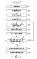
- FIG. 10 is a flowchart showing the flow of the eye fatigue inspection (eye fatigue inspection method) of the eyes 9R and 9L to be examined by the eye fatigue inspection apparatus 10.
- the optometrist displays the target on the target display unit 13 after the patient places his / her chin on the face receiving part (not shown) of the optometry table 11 (step S1, target display step of the present invention) Equivalent).
- the patient's eyes 9R and 9L are in a state of viewing (naturally looking) the test target 19 through the dichroic mirrors 14R and 14L, respectively.
- the optometrist performs an examination start operation using an operation unit (not shown) of the eye fatigue examination apparatus 10 (step S2).
- near-infrared light having a wavelength of 950 nm is irradiated from the infrared light sources 12R and 12L to the eyes 9R and 9L. Further, near infrared light having a wavelength of 840 nm is emitted from the semiconductor element 40 of the measurement units 16R and 16L.
- the near-infrared light having a wavelength of 840 nm enters the eye 9R and 9L through the collimating lens 41, the beam splitter 42, the mirror 32, the dichroic mirror 31, the objective lens 30, and the dichroic mirrors 14R and 14L, respectively. Thereby, near-infrared light of two wavelengths enters the eye to be examined 9R and 9L (step S3).
- the two-wavelength near-infrared light incident on the eye 9R, 9L is reflected by the eye 9R, 9L, then passes through the optical paths 21R, 21L and the dichroic mirrors 14R, 14L, and the objective lens 30 of the measurement units 16R, 16L. Respectively.
- the inspection target 19 is visually observed with the eyes 9R and 9L (natural vision: It is possible to objectively examine eye fatigue without leaving a sense of incongruity in the patient with both eyes open.
- Near-infrared light having a wavelength of 950 nm incident on the objective lens 30 is received by the image sensor 37 through the dichroic mirror 31, the relay lens 35, and the imaging lens 36, and a light reception signal is output from the image sensor 37 to the inspection apparatus body 17. Is done. Further, near-infrared light having a wavelength of 950 nm incident on the objective lens 30 is received by the image sensor 46 through the dichroic mirror 31, the mirror 32, the beam splitter 42, the mirror 43, the imaging lens 44, and the Hartmann plate 45 and imaged. A light reception signal is output from the element 46 to the inspection apparatus body 17 (step S4).
- the transmittance adjusting unit 50 reduces the transmittance corresponding to one of the transmission regions 23R and 23L of the liquid crystal shutters 15R and 15L continuously or stepwise with time, and corresponds to the other of the transmission regions 23R and 23L.
- the transmittance is maintained constant (for example, maximum transmittance).
- the transmittance difference between the transmission regions 23R and 23L increases continuously or stepwise over time (step S5, corresponding to the light amount difference adjustment step of the present invention).
- step S5 corresponding to the light amount difference adjustment step of the present invention.
- the difference in the amount of visible light incident on each of the eyes 9R and 9L is also increased continuously or stepwise.
- a Bagolini red filter bar (hereinafter simply referred to as BRFB) used for subjective examinations such as perspective and oblique positions.
- BRFB Bagolini red filter bar
- a method of using can be considered.
- the examination results vary depending on the procedure by the optometrist.
- the fusion may be destroyed at the first filter wearing time of BRFB.
- the filter transmittance of BRFB does not change equally, the above-described specific transmittance difference cannot be obtained accurately. Therefore, an accurate inspection method for eye fatigue cannot be performed by a subjective inspection method using BRFB.
- the transmittance difference between the transmission regions 23R and 23L can be continuously or stepwise expanded by automatic control by the transmittance adjustment unit 50, an error caused by the procedure of the optometrist is eliminated. It can be eliminated and accurate inspection can be performed.
- the transmittance difference between the transmission regions 23R and 23L can be zero at the start of inspection, the fusion is prevented from being destroyed at the start of inspection.
- the transmittance difference between the transmission regions 23R and 23L can be changed equally, the above-described specific transmittance difference can be accurately obtained.
- the line-of-sight direction detection unit 51 uses the image measurement method described with reference to FIGS. 7 and 8 based on the light reception signal input from the image sensor 37 of the anterior segment observation system 25 of both the measurement units 16R and 16L. Then, the line-of-sight directions of the eyes 9R and 9L to be examined are detected (step S6, corresponding to the line-of-sight direction detection step of the present invention). Then, the gaze direction detection unit 51 outputs the detection result of the gaze direction of the eyes 9R and 9L to be determined to the determination unit 53.
- the focus position detection unit 52 starts detecting the focus positions of the eyes 9R and 9L.
- the focus position detection unit 52 measures the wavefront aberration of the eyes 9R and 9L based on the light reception signals input from the imaging elements 46 of both aberration measurement systems 26 of the measurement units 16R and 16L, and the measurement result of the wavefront aberration
- the focus positions of the eye to be examined 9R, 9L are detected based on (Step S7).
- the focus position detection unit 52 outputs the detection results of the focus positions of the eyes 9R and 9L to be determined to the determination unit 53.
- the determination unit 53 Based on the visual line direction detection result input from the visual line direction detection unit 51 and the focus position detection result input from the focus position detection unit 52, the determination unit 53 visually observes the visual target. It is determined whether or not there is a change in the viewing direction (pupil position, Purkinje image 59p position) from the state (step S8). At this time, the detection accuracy of the determination can be improved as described above by using the focus position detection result of the eyes 9R and 9L to determine whether or not there is a change in the line-of-sight direction.
- step S8 the processing from step S5 to step S8 described above is repeatedly executed until the determination unit 53 determines that there is a change in the line-of-sight direction (NO in step S8).
- the transmittance difference between the transmission regions 23R and 23L increases with the passage of time, so that the difference in the amount of visible light incident on the subject's eyes 9R and 9L increases with the passage of time.
- FIGS. 9A to 9C when the transmittance difference (light quantity difference) between the transmission regions 23R and 23L is enlarged beyond a certain range, the patient is inspected by the eyes 9R and 9L. In this case, the image of the inspection target 19 that is being visually observed cannot be recognized as one image, and the fusion image is destroyed.
- a change in the line-of-sight direction of the eye to be examined 9R, 9L accompanying an increase in the transmittance difference (light quantity difference) occurs, and this change is detected by the determination unit 53.
- the transmittance difference determination unit 54 When the determination unit 53 determines that a change in the line-of-sight direction of the eyes 9R and 9L due to the increase in the transmittance difference (disruption of the fusion) has occurred (YES in step S8), the transmittance difference determination unit 54 The transmittance of the transmission regions 23R and 23L at the time when a change in the line-of-sight direction occurs is acquired from the rate adjusting unit 50. Thereby, the specific transmittance difference is determined by the transmittance difference determining unit 54 (step S9, corresponding to the light amount difference determining step of the present invention). Then, the transmittance difference determining unit 54 outputs transmittance difference information indicating the determined specific transmittance difference to the output unit 55.
- the output unit 55 Upon receiving the transmittance difference information from the transmittance difference determining unit 54, the output unit 55 uses the transmittance difference information as an index indicating the eye fatigue of the eyes 9R and 9L to be displayed on the display unit 56 and the storage unit 57. Each is output (step S10, corresponding to the output step of the present invention). As a result, the transmittance difference information is displayed on the display unit 56 and stored in the storage unit 57, so that the doctor performs eye fatigue of the subject's eyes 9R and 9L based on the displayed or stored transmittance difference information. Can be diagnosed and evaluated.
- the objective test (evaluation) method useful for the diagnosis and treatment of the above-mentioned CVS can be performed by measuring eye fatigue in middle-aged and elderly groups.
- eye fatigue can be inspected (evaluated), it is possible to develop a spectacle lens that is less likely to get tired or a 3D display.
- continuous or stepwise (equal difference) enlargement of the transmittance difference between the transmission regions 23R and 23L can be automatically performed, so that the eye fatigue of the eyes 9R and 9L to be examined can be accurately inspected. Is possible.
- the dichroic mirrors 14R and 14L that transmit visible light and reflect near-infrared light (measurement light) are arranged in the optical paths 21R and 21L, respectively, so that the patient visually checks the test target 19.
- the eye fatigue of the eyes 9R and 9L to be examined can be inspected while keeping the natural state (natural vision).
- the dichroic mirrors 14R and 14L are disposed in the optical paths 21R and 21L, respectively, but one dichroic mirror 60 (see FIGS. 11 and 12) is disposed so as to straddle the two optical paths 21R and 21L. May be.
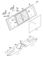
- FIG. 11 is a perspective view showing a schematic configuration of an eye fatigue inspection device 10A according to the second embodiment including a dichroic mirror 60 instead of the dichroic mirrors 14R and 14L.
- FIG. 12 is a front view of the dichroic mirror 60 as viewed from the target display unit 13 side.
- the eye fatigue inspection device 10A is basically the same as the eye fatigue inspection device 10 of the first embodiment except that the eye fatigue inspection device 10A includes a dichroic mirror 60, stereo cameras 62R and 62L, unit support bases 63R and 63L, and mirrors 64R and 64L. Is the same configuration. For this reason, the same functions or configurations as those of the first embodiment are denoted by the same reference numerals and description thereof is omitted.
- the dichroic mirror 60 is disposed so as to straddle the optical paths 21R and 21L in a state inclined 45 ° downward with respect to the optical paths 21R and 21L. Similar to the dichroic mirrors 14R and 14L of the first embodiment, the dichroic mirror 60 transmits visible light (light in the first wavelength range of the present invention) and near infrared light (second wavelength range of the present invention). Of light) is reflected. Thereby, the test target 19 can be visually observed (natural vision) with the eyes 9R and 9L.
- the dichroic mirror 60 directs near-infrared light traveling along the optical paths 21R and 21L in the near-infrared light reflected by the eyes 9R and 9L to the lower side of the optical paths 21R and 21L, respectively. Reflect.
- the liquid crystal shutters 15R and 15L described above are attached to the surface of the dichroic mirror 60 on the target display unit 13 side.
- the liquid crystal shutters 15R and 15L are attached to the dichroic mirror 60 so as to be positioned on the optical paths 21R and 21L, respectively.
- the above-described transmittance adjusting unit 50 (see FIG. 5) enlarges the difference in transmittance between the transmission regions 23R and 23L of the liquid crystal shutters 15R and 15L, and thus the eye 9R to be examined is the same as in the first embodiment.
- the difference in the amount of visible light incident on 9L can be increased.
- the stereo cameras 62R and 62L constitute a part of the line-of-sight direction detection unit of the present invention.
- the face receiving unit (Not shown).
- the stereo cameras 62R and 62L simultaneously image the subject's eyes 9R and 9L from two directions to generate a stereo image signal, and each of the stereo image signals for the eyes 9R and 9L to be detected is a gaze direction detection unit 51 (see FIG. 5). ).
- the line-of-sight direction detection unit 51 of the second embodiment analyzes the stereo imaging signals for the eyes to be examined 9R and 9L input from the stereo cameras 62R and 62L, respectively, and detects the line-of-sight directions of the eyes 9R and 9L. .
- a method for detecting the line-of-sight direction of the subject eyes 9R and 9L from the stereo image signals obtained by stereo imaging of the subject eyes 9R and 9L is a known technique, and a detailed description thereof will be omitted.
- the unit support bases 63R and 63L are disposed below the dichroic mirror 60.
- a mirror 64R and a measurement unit 16R are disposed on the unit support base 63R, and a mirror 64L and a measurement unit 16L are disposed on the unit support base 63L.
- the unit support bases 63R and 63L can be adjusted in position in a direction parallel to the eye width direction of the subject eyes 9R and 9L. Thereby, the near-infrared light reflected by the dichroic mirror 60 to the lower side of the optical paths 21R and 21L can be made incident on the mirrors 64R and 64L, respectively.
- the mirror 64R reflects near-infrared light reflected by the dichroic mirror 60 to the lower side of the optical path 21R toward the measurement unit 16R.
- the mirror 64L reflects near-infrared light reflected by the dichroic mirror 60 to the lower side of the optical path 21L toward the measurement unit 16L.
- the mirrors 64R and 64L can be adjusted to rotate around an axis perpendicular to the upper surfaces of the unit support bases 63R and 63L.
- the measurement units 16R and 16L according to the second embodiment have a configuration in which the anterior ocular segment observation system 25 is mainly omitted from the measurement units 16R and 16L according to the first embodiment illustrated in FIG. 4 and are directed toward the mirrors 64R and 64L.
- Near infrared light having a wavelength of 840 nm is emitted.
- near-infrared light having a wavelength of 840 nm is incident on the eyes 9R and 9L through the mirrors 64R and 64L and the dichroic mirror 60, respectively.
- near-infrared light having a wavelength of 840 nm reflected by the eyes 9R and 9L enters the measurement units 16R and 16L via the optical paths 21R and 21L, the dichroic mirror 60, and the mirrors 64R and 64L, respectively.
- the aberration measurement system 26 (see FIG. 4) of the measurement units 16R and 16L receives near-infrared light having a wavelength of 840 nm reflected by the eyes 9R and 9L, and receives a plurality of near-infrared lights.
- a light reception signal indicating a point image is output to the inspection apparatus main body 17.
- the inspection apparatus main body 17 of the second embodiment has basically the same configuration as the inspection apparatus main body 17 of the first embodiment except that the visual direction detection method by the visual direction detection unit 51 is different. The detailed explanation is omitted.
- the transmittance of the transmission regions 23R and 23L in a state in which the patient views the inspection target 19 through the dichroic mirror 60 (natural vision). It is possible to detect a change in the line-of-sight direction of the eyes 9R and 9L to be inspected due to the enlargement of the difference (destruction of the fusion image). As a result, the same effect as the eye fatigue inspection device 10 of the first embodiment can be obtained.
- the liquid crystal shutters 15R and 15L are arranged on the optical paths 21R and 21L, respectively.
- one liquid crystal shutter 70 (see FIG. 13) extends over the two optical paths 21R and 21L. ) May be arranged.
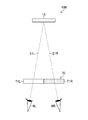
- FIG. 13 is a top view showing a schematic configuration of an eye fatigue inspection device 10B of the third embodiment including a liquid crystal shutter 70 instead of the liquid crystal shutters 15R and 15L.
- FIG. 13 illustrations other than the visual target display unit 13 and the liquid crystal shutter 70 are omitted, but the eye fatigue inspection device 10 ⁇ / b> B has the eye fatigue of the first embodiment except that the liquid crystal shutter 70 is provided.
- the configuration is basically the same as that of the inspection apparatus 10 or the eye fatigue inspection apparatus 10A of the second embodiment.
- the liquid crystal shutter 70 constitutes a part of the light amount difference adjustment unit of the present invention, and is disposed so as to straddle the optical paths 21R and 21L.
- the liquid crystal shutter 70 can adjust the light transmittance for each liquid crystal pixel, and includes a transmissive region 71R that transmits visible light that passes through the optical path 21R and a transmissive region 71L that transmits visible light that passes through the optical path 21L. ing.
- the transmittance of the transmission regions 71R and 71L is adjusted by the above-described transmittance adjusting unit 50 (see FIG. 5).
- regions 71R and 71L can be expanded by decreasing one transmittance
- the difference in the amount of visible light incident on each of the eyes 9R and 9L can be increased.
- the eye fatigue inspection apparatus 10B according to the third embodiment is different from the liquid crystal shutters 15R and 15L according to the above embodiments except that the liquid crystal shutter 70 is different from the liquid crystal shutters 15R and 15L according to the above embodiments. Since the configuration is basically the same, the same effects as those of the above embodiments can be obtained.
- the liquid crystal shutters 15R, 15L, and 70 are used to enlarge the difference in the amount of visible light incident on the subject's eyes 9R and 9L.
- Various devices or members capable of adjusting (reducing) light transmittance such as an ND (Neutral Density) filter may be used.
- FIG. 14 is a schematic diagram of another embodiment in which a plurality of ND filters 76 provided in the turret 75 are used to enlarge the difference in the amount of visible light incident on each of the eyes 9R and 9L.
- the turret 75 is provided between the dichroic mirrors 14 ⁇ / b> R and 14 ⁇ / b> L (or the dichroic mirror 60 shown in FIG. 11) and the visual target display unit 13.
- the turret 75 is provided with a plurality of ND filters 76 having different visible light transmittances (concentrations) stepwise along the circumferential direction thereof.
- the turret 75 rotates about its rotation axis, thereby inserting a plurality of ND filters 76 into one of the optical paths 21R and 21L (in the optical path 21R in FIG. 14) in descending order of transmittance.
- the amount of visible light incident on the eye 9R decreases stepwise, and the amount of visible light incident on the eye 9L is maintained constant, so that the visible light incident on the eyes 9R and 9L, respectively.
- the difference in the amount of light can be enlarged.
- liquid crystal shutters 15R and 15L described above may be replaced with variable density filters, and a specific description thereof will be omitted.
- the liquid crystal shutters 15R, 15L, and 70 are arranged at positions away from the eye to be examined 9R and 9L.
- the liquid crystal shutters 15R, 15L, and 70 are disposed in the frame of goggles worn by the patient or in the lens frame of glasses.
- Shutters 15R, 15L, etc. may be provided to increase the difference in the amount of visible light incident on the eye 9R, 9L, respectively.
- the liquid crystal shutters 15R and 15L are disposed on the optical paths 21R and 21L, respectively.
- the liquid crystal shutter is disposed on only one of the optical paths 21R and 21L, and the eye to be examined. You may enlarge the light quantity difference of the visible light which each enters 9R and 9L.
- the focus positions of the eyes 9R and 9L to be examined are detected by the aberration measurement system 26 and the focus position detection unit 52.
- the detection of the focus position may be omitted.
- the gaze direction and focus position of the eye 9R to be examined and the gaze direction and focus position of the eye 9L are simultaneously detected by the two measurement units 16R and 16L.
- the detection of the line-of-sight direction and focus position of the optometry 9R and the detection of the line-of-sight direction and focus position of the eye 9L may be alternately performed while switching at high speed.
- the line-of-sight direction and the focus position of the eyes 9R and 9L are detected using near-infrared light having a wavelength of 950 nm and a wavelength of 840 nm as light in the second wavelength range of the present invention.
- the line-of-sight direction and the focus position may be detected by using light in other wavelength regions that do not give the light.
- the amount of visible light incident on one of the eyes 9R and 9L is decreased, and the amount of visible light incident on the other of the eyes 9R and 9L is kept constant, thereby maintaining the eye 9R. , 9L, the difference in the amount of visible light incident on each of the eyes 9L is enlarged.
- the method for adjusting the amount of light incident on one and the other of the eyes 9R, 9L is not particularly limited. .
- 10, 10A, 10B eye fatigue inspection device 12R, 12L infrared light source, 13 target display unit, 14R, 14L, 60 dichroic mirror, 15R, 15L, 70 liquid crystal shutter, 16R, 16L measurement unit, 17 inspection device body, 19 Inspection target, 21R, 21L optical path, 23R, 23L, 71R, 71L transmission region, 25 anterior ocular segment observation system, 26 aberration measurement system, 50 transmittance adjustment unit, 51 gaze direction detection unit, 52 focus position detection unit, 53 determination unit, 54 transmittance difference determination unit, 55 output unit, 62R, 62L stereo camera, 75 turret
Landscapes
- Health & Medical Sciences (AREA)
- Life Sciences & Earth Sciences (AREA)
- Engineering & Computer Science (AREA)
- Medical Informatics (AREA)
- Surgery (AREA)
- Biophysics (AREA)
- Biomedical Technology (AREA)
- Heart & Thoracic Surgery (AREA)
- Physics & Mathematics (AREA)
- Molecular Biology (AREA)
- Ophthalmology & Optometry (AREA)
- Animal Behavior & Ethology (AREA)
- General Health & Medical Sciences (AREA)
- Public Health (AREA)
- Veterinary Medicine (AREA)
- Human Computer Interaction (AREA)
- Eye Examination Apparatus (AREA)
Abstract
L'invention concerne un dispositif d'examen de fatigue oculaire et un procédé d'examen de fatigue oculaire grâce auquel il est possible d'examiner la fatigue oculaire d'yeux à examiner indépendamment de l'âge d'un patient. Le dispositif d'examen de fatigue oculaire comporte : une unité de réglage de différence de niveaux de lumière qui augmente une différence de niveaux de lumière entre des faisceaux qui entrent dans les yeux gauche et droit qui doivent être examinés, respectivement ; une unité de détection de direction du regard qui détecte les directions du regard des yeux qui doivent être examinés tandis que l'unité de réglage de différence de niveau de lumière augmente la différence de niveaux de lumière ; et une unité de détermination de différence de niveaux de lumière qui détermine, sur la base des résultats de détection de l'unité de détection de direction du regard, une différence spécifique de niveaux de lumière à laquelle des changements des directions de regard se produisent en association avec l'augmentation de la différence de niveaux de lumière.
Priority Applications (2)
| Application Number | Priority Date | Filing Date | Title |
|---|---|---|---|
| US16/085,595 US10959615B2 (en) | 2016-03-18 | 2017-02-20 | Eye-fatigue examining device and eye-fatigue examining method |
| EP17766232.7A EP3430976B1 (fr) | 2016-03-18 | 2017-02-20 | Dispositif d'examen de fatigue oculaire et procédé d'examen de fatigue oculaire |
Applications Claiming Priority (2)
| Application Number | Priority Date | Filing Date | Title |
|---|---|---|---|
| JP2016055553A JP6714402B2 (ja) | 2016-03-18 | 2016-03-18 | 眼疲労検査装置及び眼疲労検査方法 |
| JP2016-055553 | 2016-03-18 |
Publications (1)
| Publication Number | Publication Date |
|---|---|
| WO2017159225A1 true WO2017159225A1 (fr) | 2017-09-21 |
Family
ID=59851436
Family Applications (1)
| Application Number | Title | Priority Date | Filing Date |
|---|---|---|---|
| PCT/JP2017/006177 Ceased WO2017159225A1 (fr) | 2016-03-18 | 2017-02-20 | Dispositif d'examen de fatigue oculaire et procédé d'examen de fatigue oculaire |
Country Status (4)
| Country | Link |
|---|---|
| US (1) | US10959615B2 (fr) |
| EP (1) | EP3430976B1 (fr) |
| JP (1) | JP6714402B2 (fr) |
| WO (1) | WO2017159225A1 (fr) |
Families Citing this family (10)
| Publication number | Priority date | Publication date | Assignee | Title |
|---|---|---|---|---|
| US11786694B2 (en) | 2019-05-24 | 2023-10-17 | NeuroLight, Inc. | Device, method, and app for facilitating sleep |
| JP7213492B2 (ja) * | 2019-06-24 | 2023-01-27 | 株式会社Qdレーザ | 視覚検査装置及び視覚検査方法 |
| JP7577064B2 (ja) | 2019-08-16 | 2024-11-01 | 株式会社トプコン | 眼科装置及び眼科システム |
| US12333859B2 (en) | 2019-09-06 | 2025-06-17 | Semiconductor Energy Laboratory Co., Ltd. | Information processor performing arithmetic operation using machine learning |
| JP7406413B2 (ja) * | 2020-03-13 | 2023-12-27 | 株式会社トプコン | 眼科装置 |
| DE102020114212B3 (de) * | 2020-05-27 | 2021-10-14 | Schwind Eye-Tech-Solutions Gmbh | Verfahren zum Bestimmen der Position des Laserfokus eines Laserstrahls eines augenchirurgischen Lasers, sowie Behandlungsvorrichtung |
| KR102535860B1 (ko) * | 2021-02-23 | 2023-05-26 | 인제대학교 산학협력단 | 간헐외사시 중증도 평가 방법 및 이를 이용한 간헐외사시 중증도 평가 장치 |
| TWI778779B (zh) * | 2021-09-06 | 2022-09-21 | 明達醫學科技股份有限公司 | 應用於眼睛檢測裝置之引導固定方法 |
| JP7756591B2 (ja) * | 2022-03-31 | 2025-10-20 | 株式会社トプコン | 眼科装置 |
| JP2025146362A (ja) | 2024-03-22 | 2025-10-03 | 株式会社トプコン | 眼科装置 |
Citations (4)
| Publication number | Priority date | Publication date | Assignee | Title |
|---|---|---|---|---|
| JPS60253429A (ja) * | 1984-05-29 | 1985-12-14 | キヤノン株式会社 | 眼科検査装置 |
| JP2004298289A (ja) * | 2003-03-28 | 2004-10-28 | Topcon Corp | 三次元観察状態測定装置及び方法 |
| JP2006305325A (ja) * | 2005-03-31 | 2006-11-09 | Topcon Corp | 眼科装置 |
| JP2009178502A (ja) * | 2008-02-01 | 2009-08-13 | Topcon Corp | 眼科測定装置 |
Family Cites Families (35)
| Publication number | Priority date | Publication date | Assignee | Title |
|---|---|---|---|---|
| US5094521A (en) * | 1990-11-07 | 1992-03-10 | Vision Research Laboratories | Apparatus for evaluating eye alignment |
| US5530492A (en) * | 1993-03-22 | 1996-06-25 | Medoptics Limited | Ophthalmological instrument for producing dichoptic stimuli on a visual display terminal |
| DE69433650T2 (de) * | 1993-08-20 | 2004-08-12 | Seiko Epson Corp. | Am Kopf montierte Bildanzeigevorrichtung |
| EP0716329B1 (fr) * | 1994-06-23 | 2003-08-27 | Seiko Epson Corporation | Dispositif de presentation monte sur des lunettes |
| US5764340A (en) * | 1996-08-02 | 1998-06-09 | Hofeldt; Albert J. | Portable device for evaluation of binocular vision problems |
| US7312765B2 (en) * | 1998-08-05 | 2007-12-25 | Microvision, Inc. | Display system and method for reducing the magnitude of or eliminating a visual artifact caused by a shift in a viewer's gaze |
| JP4173296B2 (ja) | 2001-09-07 | 2008-10-29 | 雅義 梶田 | 眼調節機能測定装置 |
| GB0210288D0 (en) * | 2002-05-04 | 2002-06-12 | Univ Nottingham | Ocular display apparatus for assessment and measurement of and for treatment of ocular disorders, and methods therefor |
| US7033025B2 (en) * | 2002-05-17 | 2006-04-25 | Virtocc, Inc. | Interactive occlusion system |
| US7290878B1 (en) * | 2003-10-15 | 2007-11-06 | Albert John Hofeldt | Machine for binocular testing and a process of formatting rival and non-rival stimuli |
| JP4717728B2 (ja) * | 2005-08-29 | 2011-07-06 | キヤノン株式会社 | ステレオ表示装置及びその制御方法 |
| JP2010099335A (ja) * | 2008-10-24 | 2010-05-06 | National Institute Of Advanced Industrial Science & Technology | 立体視機能検査方法 |
| EP2329761A1 (fr) * | 2009-12-02 | 2011-06-08 | RetCorr AB | Appareil et procédé pour établir et/ou améliorer une vision binoculaire améliorée |
| KR20110107025A (ko) * | 2010-03-24 | 2011-09-30 | 삼성전자주식회사 | 디스플레이 장치 및 디스플레이 장치의 제어 방법 |
| JP5565258B2 (ja) * | 2010-10-12 | 2014-08-06 | ソニー株式会社 | 画像処理装置、画像処理方法及びプログラム |
| DE102011054833A1 (de) | 2010-10-29 | 2012-05-03 | Hoya Corp. | Verfahren zum Messen der binokularen Sehleistung, Programm zum Messen der binokularen Sehleistung, Verfahren zum Entwerfen von Brillengläsern und Verfahren zur Herstellung von Brillengläsern |
| JP5715797B2 (ja) * | 2010-10-29 | 2015-05-13 | Hoya株式会社 | 両眼視機能測定方法、両眼視機能測定プログラム、眼鏡レンズの設計方法、及び眼鏡レンズの製造方法 |
| CN103281959A (zh) * | 2011-05-20 | 2013-09-04 | 松下电器产业株式会社 | 视觉疲劳度测定装置、视觉疲劳度测定方法、视觉疲劳度测定系统及三维眼镜 |
| US9560960B2 (en) * | 2011-10-19 | 2017-02-07 | Albert John Hofeldt | Amblyometer for balancing bridging rivalrous binocular vision |
| JP2013102952A (ja) * | 2011-11-14 | 2013-05-30 | Samsung Electronics Co Ltd | 眼精疲労測定装置、電子機器、眼精疲労測定方法、及びプログラム |
| KR20130054176A (ko) | 2011-11-14 | 2013-05-24 | 삼성전자주식회사 | 3d 영상의 안정피로 측정 방법 및 장치 |
| JP2014124308A (ja) * | 2012-12-26 | 2014-07-07 | Panasonic Corp | 眼電位生成装置、眼電位生成方法およびビューワー |
| US8931905B2 (en) * | 2013-01-25 | 2015-01-13 | James Waller Lambuth Lewis | Binocular measurement method and device |
| JP6171425B2 (ja) * | 2013-03-12 | 2017-08-02 | セイコーエプソン株式会社 | 虚像表示装置 |
| PT3065624T (pt) * | 2013-11-07 | 2018-11-16 | Ohio State Innovation Foundation | Deteção automatizada do alinhamento ocular |
| EP3108444A4 (fr) * | 2014-02-19 | 2017-09-13 | Evergaze, Inc. | Appareil et procédé pour optimiser, augmenter ou améliorer la vision |
| GB2524500A (en) * | 2014-03-24 | 2015-09-30 | Nottingham University Hospitals Nhs Trust | Apparatus and methods for the treatment of ocular disorders |
| JP6367673B2 (ja) * | 2014-09-29 | 2018-08-01 | 京セラ株式会社 | 電子機器 |
| EP3954270A1 (fr) * | 2015-01-20 | 2022-02-16 | Green C.Tech Ltd | Procédé et système de diagnostic automatique de la vue |
| EA033741B1 (ru) * | 2015-03-01 | 2019-11-21 | Novasight Ltd | Система и способ для измерения движений глазного яблока |
| CN107530034A (zh) * | 2015-03-16 | 2018-01-02 | 奇跃公司 | 增强现实脉冲血氧定量法 |
| KR102586069B1 (ko) * | 2015-07-03 | 2023-10-05 | 에씰로 앙터나시오날 | 증강 현실을 위한 방법 및 시스템 |
| US9905168B1 (en) * | 2015-12-28 | 2018-02-27 | Oculus Vr, Llc | Luminance-based non-uniformity correction for display panels in head-mounted displays |
| US10516879B2 (en) * | 2016-08-12 | 2019-12-24 | Avegant Corp. | Binocular display with digital light path length modulation |
| JP6922338B2 (ja) * | 2017-03-31 | 2021-08-18 | 株式会社ニデック | 自覚式検眼装置 |
-
2016
- 2016-03-18 JP JP2016055553A patent/JP6714402B2/ja active Active
-
2017
- 2017-02-20 US US16/085,595 patent/US10959615B2/en active Active
- 2017-02-20 EP EP17766232.7A patent/EP3430976B1/fr active Active
- 2017-02-20 WO PCT/JP2017/006177 patent/WO2017159225A1/fr not_active Ceased
Patent Citations (4)
| Publication number | Priority date | Publication date | Assignee | Title |
|---|---|---|---|---|
| JPS60253429A (ja) * | 1984-05-29 | 1985-12-14 | キヤノン株式会社 | 眼科検査装置 |
| JP2004298289A (ja) * | 2003-03-28 | 2004-10-28 | Topcon Corp | 三次元観察状態測定装置及び方法 |
| JP2006305325A (ja) * | 2005-03-31 | 2006-11-09 | Topcon Corp | 眼科装置 |
| JP2009178502A (ja) * | 2008-02-01 | 2009-08-13 | Topcon Corp | 眼科測定装置 |
Also Published As
| Publication number | Publication date |
|---|---|
| EP3430976A4 (fr) | 2019-04-17 |
| JP6714402B2 (ja) | 2020-06-24 |
| US20190099076A1 (en) | 2019-04-04 |
| EP3430976B1 (fr) | 2020-03-25 |
| EP3430976A1 (fr) | 2019-01-23 |
| US10959615B2 (en) | 2021-03-30 |
| JP2017169601A (ja) | 2017-09-28 |
Similar Documents
| Publication | Publication Date | Title |
|---|---|---|
| JP6714402B2 (ja) | 眼疲労検査装置及び眼疲労検査方法 | |
| EP2187802B1 (fr) | Système de mesure ophtalmique multifonctionnel et procédé correspondant | |
| EP2079355B1 (fr) | Méthode et système de prescription de lunettes | |
| CN106963335B (zh) | 主观式检眼装置 | |
| US9462939B2 (en) | Objective phoropter system | |
| JP7126661B2 (ja) | 眼科装置及び眼科装置の作動方法 | |
| KR101812249B1 (ko) | 사시 자동측정기구 | |
| JP6853496B2 (ja) | 検眼装置及び検眼プログラム | |
| JP2018110726A (ja) | 自覚式検眼装置及び自覚式検眼プログラム | |
| JP7298134B2 (ja) | 検眼システム | |
| JP2018047049A (ja) | 自覚式検眼装置、及び自覚式検眼プログラム | |
| JP2022038942A (ja) | 検眼装置及び検眼装置の制御プログラム | |
| JP5011144B2 (ja) | 眼科測定装置 | |
| JP7098880B2 (ja) | 自覚式検眼装置及び自覚式検眼プログラム | |
| KR20220070086A (ko) | 시력 측정 장치 및 이를 포함하는 시력 측정 시스템 | |
| JP2018171139A (ja) | 自覚式検眼装置 | |
| JP7600985B2 (ja) | 検眼装置 | |
| JP2022157348A (ja) | 眼科装置 | |
| WO2016195067A1 (fr) | Appareil de test de la vision | |
| JP7078187B2 (ja) | 自覚式検眼装置及び自覚式検眼プログラム | |
| JP2025027668A (ja) | 眼科装置及び被検眼の検査方法 | |
| WO2022209992A1 (fr) | Dispositif ophtalmologique | |
| JP2021010415A (ja) | 眼屈折力測定装置 | |
| JP2017077418A (ja) | 眼科装置 |
Legal Events
| Date | Code | Title | Description |
|---|---|---|---|
| NENP | Non-entry into the national phase |
Ref country code: DE |
|
| WWE | Wipo information: entry into national phase |
Ref document number: 2017766232 Country of ref document: EP |
|
| ENP | Entry into the national phase |
Ref document number: 2017766232 Country of ref document: EP Effective date: 20181018 |
|
| 121 | Ep: the epo has been informed by wipo that ep was designated in this application |
Ref document number: 17766232 Country of ref document: EP Kind code of ref document: A1 |