WO2017159268A1 - Dispositif de commande pour transmission à variation continue et procédé de commande pour transmission à variation continue - Google Patents
Dispositif de commande pour transmission à variation continue et procédé de commande pour transmission à variation continue Download PDFInfo
- Publication number
- WO2017159268A1 WO2017159268A1 PCT/JP2017/006816 JP2017006816W WO2017159268A1 WO 2017159268 A1 WO2017159268 A1 WO 2017159268A1 JP 2017006816 W JP2017006816 W JP 2017006816W WO 2017159268 A1 WO2017159268 A1 WO 2017159268A1
- Authority
- WO
- WIPO (PCT)
- Prior art keywords
- advance
- compensation
- continuously variable
- variable transmission
- ratio
- Prior art date
- Legal status (The legal status is an assumption and is not a legal conclusion. Google has not performed a legal analysis and makes no representation as to the accuracy of the status listed.)
- Ceased
Links
Images




Classifications
-
- F—MECHANICAL ENGINEERING; LIGHTING; HEATING; WEAPONS; BLASTING
- F16—ENGINEERING ELEMENTS AND UNITS; GENERAL MEASURES FOR PRODUCING AND MAINTAINING EFFECTIVE FUNCTIONING OF MACHINES OR INSTALLATIONS; THERMAL INSULATION IN GENERAL
- F16H—GEARING
- F16H59/00—Control inputs to control units of change-speed- or reversing-gearings for conveying rotary motion
- F16H59/68—Inputs being a function of gearing status
-
- F—MECHANICAL ENGINEERING; LIGHTING; HEATING; WEAPONS; BLASTING
- F16—ENGINEERING ELEMENTS AND UNITS; GENERAL MEASURES FOR PRODUCING AND MAINTAINING EFFECTIVE FUNCTIONING OF MACHINES OR INSTALLATIONS; THERMAL INSULATION IN GENERAL
- F16H—GEARING
- F16H61/00—Control functions within control units of change-speed- or reversing-gearings for conveying rotary motion ; Control of exclusively fluid gearing, friction gearing, gearings with endless flexible members or other particular types of gearing
- F16H61/04—Smoothing ratio shift
-
- F—MECHANICAL ENGINEERING; LIGHTING; HEATING; WEAPONS; BLASTING
- F16—ENGINEERING ELEMENTS AND UNITS; GENERAL MEASURES FOR PRODUCING AND MAINTAINING EFFECTIVE FUNCTIONING OF MACHINES OR INSTALLATIONS; THERMAL INSULATION IN GENERAL
- F16H—GEARING
- F16H61/00—Control functions within control units of change-speed- or reversing-gearings for conveying rotary motion ; Control of exclusively fluid gearing, friction gearing, gearings with endless flexible members or other particular types of gearing
- F16H61/66—Control functions within control units of change-speed- or reversing-gearings for conveying rotary motion ; Control of exclusively fluid gearing, friction gearing, gearings with endless flexible members or other particular types of gearing specially adapted for continuously variable gearings
-
- F—MECHANICAL ENGINEERING; LIGHTING; HEATING; WEAPONS; BLASTING
- F16—ENGINEERING ELEMENTS AND UNITS; GENERAL MEASURES FOR PRODUCING AND MAINTAINING EFFECTIVE FUNCTIONING OF MACHINES OR INSTALLATIONS; THERMAL INSULATION IN GENERAL
- F16H—GEARING
- F16H59/00—Control inputs to control units of change-speed- or reversing-gearings for conveying rotary motion
- F16H59/36—Inputs being a function of speed
- F16H59/38—Inputs being a function of speed of gearing elements
- F16H59/42—Input shaft speed
Definitions
- the present invention relates to a continuously variable transmission control device and a continuously variable transmission control method.
- JP2002-106700A discloses a technique for advancing and compensating a target gear ratio by a response delay of an actual gear ratio with respect to the target gear ratio.
- a longitudinal vibration that causes a shaking in the front-rear direction at the resonance frequency of the power train. It is considered that the longitudinal vibration is generated when the torque fluctuation and the speed change of the continuously variable transmission are coupled when the stability of the transmission ratio of the continuously variable transmission is insufficient with respect to the torque fluctuation of the power train. For this reason, it is conceivable to suppress the longitudinal vibration by increasing the stability of the speed ratio of the continuously variable transmission by lead compensation.
- the present invention has been made in view of such problems, and a continuously variable transmission control device and a continuously variable transmission capable of improving the longitudinal vibration of the continuously variable transmission while ensuring the stability of the shift control. It is an object to provide a control method.
- a control device for a continuously variable transmission is a control device for a continuously variable transmission that performs feedback control based on an actual value representing a state of the continuously variable transmission.
- a first advance compensation unit that performs advance compensation; and a second advance compensation unit that is provided in series with the first advance compensation unit and that performs primary advance compensation of the feedback shift control.
- a control method for a continuously variable transmission that performs feedback control based on an actual value that represents the state of the continuously variable transmission, and performs primary advance compensation of the feedback control. And a method of controlling the continuously variable transmission, including further performing the first-order advance compensation of the feedback control.
- the secondary advance compensation can be simply performed by the two primary advance compensations. Further, by performing the secondary advance compensation, the gain can be made lower than in the case of performing the primary advance compensation. For this reason, the longitudinal vibration of the continuously variable transmission can be improved while ensuring the stability of the shift control.
- FIG. 1 is a schematic configuration diagram of a vehicle including a transmission controller.
- FIG. 2 is a schematic configuration diagram of the transmission controller.
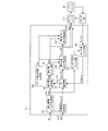
- FIG. 3 is a diagram illustrating an example of a functional block diagram of the transmission controller.
- FIG. 4 is a diagram illustrating an example of a Bode diagram of the phase advance compensator.
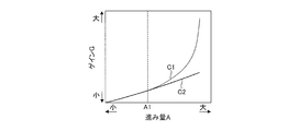
- FIG. 5 is a diagram illustrating an example of a gain change of the phase lead compensator.
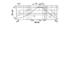
- FIG. 6 is an explanatory diagram of the influence of the frequency shift.
- FIG. 7 is a flowchart illustrating an example of control performed by the transmission controller.
- FIG. 1 is a schematic configuration diagram of a vehicle including a transmission controller 12.
- the vehicle includes an engine 1 as a power source.
- the power of the engine 1 is transmitted to the drive wheels 7 via the torque converter 2, the first gear train 3, the transmission 4, the second gear train 5, and the differential 6 that constitute the power train PT.
- the second gear train 5 is provided with a parking mechanism 8 that mechanically locks the output shaft of the transmission 4 during parking.
- the torque converter 2 includes a lock-up clutch 2a.
- the lock-up clutch 2a When the lock-up clutch 2a is engaged, slippage in the torque converter 2 is eliminated, and the transmission efficiency of the torque converter 2 is improved.
- the lock-up clutch 2a is referred to as the LU clutch 2a.
- the transmission 4 is a continuously variable transmission including a variator 20.
- the variator 20 is a continuously variable transmission mechanism that includes a pulley 21 that is a primary pulley, a pulley 22 that is a secondary pulley, and a belt 23 that is wound around the pulleys 21 and 22.
- the pulley 21 constitutes a driving side rotating element
- the pulley 22 constitutes a driven side rotating element.
- Each of the pulleys 21 and 22 includes a fixed conical plate, a movable conical plate that is disposed with a sheave surface facing the fixed conical plate, and forms a V-groove between the fixed conical plate, and a rear surface of the movable conical plate. And a hydraulic cylinder that displaces the movable conical plate in the axial direction.
- the pulley 21 includes a hydraulic cylinder 23a as a hydraulic cylinder
- the pulley 22 includes a hydraulic cylinder 23b as a hydraulic cylinder.
- the variator 20 may be a toroidal continuously variable transmission mechanism.
- the transmission 4 further includes an auxiliary transmission mechanism 30.
- the subtransmission mechanism 30 is a transmission mechanism having two forward speeds and one reverse speed, and has a first speed and a second speed having a smaller gear ratio than the first speed.
- the auxiliary transmission mechanism 30 is provided in series with the variator 20 in the power transmission path from the engine 1 to the drive wheels 7.
- the sub-transmission mechanism 30 may be directly connected to the output shaft of the variator 20 as in this example, or may be connected via another power transmission mechanism such as a shift or a gear train. Alternatively, the auxiliary transmission mechanism 30 may be connected to the input shaft side of the variator 20.
- the vehicle further includes an oil pump 10 that is driven using a part of the power of the engine 1, and a hydraulic control circuit that adjusts the hydraulic pressure generated by the oil pump 10 by supplying oil and supplies the hydraulic pressure to each part of the transmission 4. 11 and a transmission controller 12 that controls the hydraulic control circuit 11 are provided.
- the hydraulic control circuit 11 includes a plurality of flow paths and a plurality of hydraulic control valves.
- the hydraulic control circuit 11 switches a hydraulic pressure supply path by controlling a plurality of hydraulic control valves based on a shift control signal from the transmission controller 12.
- the hydraulic control circuit 11 adjusts the required hydraulic pressure from the hydraulic pressure generated by the oil pump 10 by supplying oil, and supplies the adjusted hydraulic pressure to each part of the transmission 4. As a result, the variator 20 is shifted, the sub-transmission mechanism 30 is changed, and the LU clutch 2a is engaged / released.
- FIG. 2 is a schematic configuration diagram of the transmission controller 12.
- the transmission controller 12 includes a CPU 121, a storage device 122 including a RAM / ROM, an input interface 123, an output interface 124, and a bus 125 that connects these components to each other.
- the input interface 123 includes, for example, an output signal of an accelerator opening sensor 41 that detects an accelerator opening APO that represents an operation amount of an accelerator pedal, an output signal of a rotational speed sensor 42 that detects an input side rotational speed of the transmission 4, and a pulley.
- the output signal of the rotation speed sensor 43 for detecting the rotation speed Nsec of 22 and the output signal of the rotation speed sensor 44 for detecting the output side rotation speed of the transmission 4 are input.
- the input side rotational speed of the transmission 4 is the rotational speed of the input shaft of the transmission 4, and hence the rotational speed Npri of the pulley 21.
- the output side rotational speed of the transmission 4 is the rotational speed of the output shaft of the transmission 4, and hence the rotational speed of the output shaft of the subtransmission mechanism 30.
- the input side rotational speed of the transmission 4 may be a rotational speed at a position where a gear train or the like is sandwiched between the transmission 4 and the like, for example, a turbine rotational speed of the torque converter 2. The same applies to the output side rotational speed of the transmission 4.
- the input interface 123 further includes an output signal of the vehicle speed sensor 45 that detects the vehicle speed VSP, an output signal of the oil temperature sensor 46 that detects the oil temperature TMP of the transmission 4, and an output signal of the inhibitor switch 47 that detects the position of the select lever.
- An output signal of the hydraulic sensor 50 that detects the above is input.
- a torque signal of the engine torque Te is also input to the input interface 123 from the engine controller 51 provided in the engine 1.
- the storage device 122 stores a shift control program for the transmission 4, various maps used in the shift control program, and the like.
- the CPU 121 reads and executes the shift control program stored in the storage device 122 and generates a shift control signal based on various signals input via the input interface 123. Further, the CPU 121 outputs the generated shift control signal to the hydraulic control circuit 11 via the output interface 124.
- Various values used by the CPU 121 in the calculation process and the calculation results of the CPU 121 are stored in the storage device 122 as appropriate.
- longitudinal vibration may occur at the PT resonance frequency Fpt, which is the resonance frequency of the power train PT. It is considered that the longitudinal vibration is generated by coupling the torque fluctuation and the shift of the transmission 4 when the stability of the transmission ratio of the transmission 4 is insufficient with respect to the torque fluctuation of the power train PT. For this reason, it is conceivable to suppress the longitudinal vibration by increasing the stability of the speed ratio of the transmission 4 by lead compensation.
- the controller 12 performs shift control as described below.
- the speed ratio of the variator 20 is used as the speed ratio of the transmission 4.
- the gear ratio Ratio is a general term for the gear ratios of the variator 20 including an actual gear ratio Ratio_A, a target gear ratio Ratio_D, and a final gear ratio Ratio_T, which will be described later, and includes at least one of them.
- the transmission ratio of the transmission 4 may be a through transmission ratio that is the transmission ratio of the variator 20 and the auxiliary transmission mechanism 30 as a whole.
- the transmission controller 12 is simply referred to as a controller 12.
- FIG. 3 is a diagram showing an example of a functional block diagram of the controller 12 showing a main part of the shift control.
- the controller 12 includes a target value generation unit 131, an FB compensator 132, a lead compensation on / off determination unit 133, a lead amount determination unit 134, a lead amount filter unit 135, and a first phase lead that is a first lead compensation unit.
- the compensator 136 includes a second phase lead compensator 137 that is a second lead compensation unit, a switch unit 138, an on / off command filter unit 139, a sensor value filter unit 140, and a peak value frequency determination unit 141.
- FB is an abbreviation for feedback.
- the target value generation unit 131 generates a target value for shift control.
- the target value is a target speed ratio Ratio_D based on a final speed ratio Ratio_T that is a final target speed control value with the speed ratio Ratio as a speed control value.
- the shift control value may be, for example, the primary pressure Ppri as a control parameter.
- the ultimate transmission ratio Ratio_T is preset according to the driving state of the vehicle in the shift map. For this reason, the target value generation unit 131 reads the corresponding reaching speed ratio Ratio_T from the shift map based on the detected driving state.
- the driving state of the vehicle is a vehicle speed VSP and an accelerator opening APO.
- the target value generation unit 131 calculates the target speed ratio Ratio_D based on the reached speed ratio Ratio_T.
- the target speed ratio Ratio_D is a transitional target speed ratio until the target speed ratio Ratio_T is reached, and constitutes a target speed control value.
- the calculated target gear ratio Ratio_D is input to the FB compensator 132.
- the FB compensator 132 calculates a feedback command value based on the actual speed ratio Ratio_A and the target speed ratio Ratio_D, which are actual values of the speed ratio Ratio.
- the feedback command value is, for example, a feedback primary command pressure Ppri_FB for filling an error between the actual speed ratio Ratio_A and the target speed ratio Ratio_D.
- the calculated feedback command value (feedback primary command pressure Ppri_FB) is input to the advance amount determination unit 134 and the first phase advance compensator 136.
- the advance compensation on / off determination unit 133 determines on / off of the phase advance compensation of the feedback primary command pressure Ppri_FB, that is, execution / stop of the phase advance compensation.
- Lead compensation on / off determination section 133 determines on / off of phase lead compensation according to pulley state value M.
- the pulley state value M is a value for determining whether or not the pulleys 21 and 22 are in a state in which longitudinal vibration occurs, and the rotational speed Npri, the input torque Tsec to the pulley 22, the transmission ratio Ratio, It includes the rate of change ⁇ of the ratio Ratio.
- the input torque Tsec is calculated as a value obtained by multiplying the engine torque Te by the gear ratio set between the engine 1 and the pulley 22, and thus in the present embodiment, the gear ratio of the first gear train 3 and the gear ratio of the variator 20. Can do.
- the actual speed ratio Ratio_A and the target speed ratio Ratio_D can be applied to the speed ratio Ratio.
- the speed ratio Ratio may be the actual speed ratio Ratio_A or the target speed ratio Ratio_D.
- the advance compensation on / off determination unit 133 further determines the phase of the feedback primary command pressure Ppri_FB according to the engaged state of the LU clutch 2a, the state of the driver operation on the transmission 4, and the presence or absence of a failure Determine on / off of lead compensation.
- the method for determining the on / off of the phase lead compensation performed by the lead compensation on / off determination unit 133 will be specifically described later with reference to a flowchart.
- the lead compensation on / off determination unit 133 outputs an on command when it is determined that phase lead compensation is on, and outputs an off command when it is determined that phase lead compensation is off.
- the on command and the off command are collectively referred to as an on / off command.
- the on / off command is input from the advance compensation on / off determination unit 133 to the advance amount determination unit 134 and the on / off command filter unit 139.
- the advance amount determination unit 134 determines an advance amount A for phase advance compensation of the feedback primary command pressure Ppri_FB.
- the advance amount determination unit 134 determines the advance amount Apk according to the on / off command.
- the advance amount determination unit 134 determines the advance amount Apk to be zero when an off command is input.
- the advance amount determination unit 134 determines the advance amount Apk as the first advance amount Apk1 or the second advance amount Apk2 when an ON command is input.
- the first advance amount Apk1 is set in correspondence with the case of performing first-order phase lead compensation described later, and the second advance amount Apk2 is set in correspondence with the case of performing second-order phase lead compensation described later. .
- the second advance amount Apk2 is set to 1 ⁇ 2 of the first advance amount Apk1.
- the first advance amount Apk1 is, for example, 80 deg and can be a constant value.
- the first advance amount Apk1 can be set in advance by experiments or the like.
- the advance amount Apk is input from the advance amount determination unit 134 to the advance amount filter unit 135.
- the advance amount filter unit 135 performs a filter process of the advance amount Apk.
- the advance amount filter unit 135 may be omitted.
- the advance amount Apk is input from the advance amount filter unit 135 to the first phase advance compensator 136, the second phase advance compensator 137, and the switch unit 138.
- the peak value frequency Fpk from the peak value frequency determining unit 141 is also input to the first phase lead compensator 136 and the second phase lead compensator 137.
- the peak value frequency Fpk is a frequency set according to the target frequency in the phase lead compensation. Specifically, the target frequency is the PT resonance frequency Fpt. For this reason, the peak value frequency Fpk is set to, for example, the PT resonance frequency Fpt.
- the peak value frequency Fpk is 2 Hz, for example, and is a fixed value, that is, fixed.
- the PT resonance frequency Fpt set as the target frequency to the peak value frequency Fpk does not necessarily match the actual PT resonance frequency Fpt.
- Both the first phase advance compensator 136 and the second phase advance compensator 137 are based on the input advance amount Apk and the input peak value frequency Fpk, and the primary phase advance compensation of the feedback primary command pressure Ppri_FB. I do.
- the phase advance compensation of the feedback primary command pressure Ppri_FB By performing the phase advance compensation of the feedback primary command pressure Ppri_FB, the phase advance compensation of the feedback shift control of the transmission 4 is performed.
- the first phase lead compensator 136 and the second phase lead compensator 137 are composed of a first-order low-pass filter, and correspond to the inputted advance amount Apk and further the inputted peak value frequency Fpk. By performing the filtering process, the primary phase lead compensation of the feedback primary command pressure Ppri_FB is performed.
- the second phase lead compensator 137 is provided in series with the first phase lead compensator 136.
- the feedback primary command pressure Ppri_FB subjected to the first-order phase advance compensation by the first phase advance compensator 136 is input to the second phase advance compensator 137.
- the second phase lead compensator 137 further performs the primary phase lead compensation when performing the primary phase lead compensation of the feedback primary command pressure Ppri_FB. Thereby, the secondary phase lead compensation of the feedback primary command pressure Ppri_FB is performed.
- the switch unit 138 performs the phase lead compensation by the first phase lead compensator 136 and the second phase lead compensator 137 in accordance with the input lead amount Apk, that is, the case where the second phase lead compensation is performed.
- the phase lead compensation is performed only by the first phase lead compensator 136, that is, when the first phase lead compensation is performed.
- FIG. 4 is a diagram showing an example of a Bode diagram of the phase lead compensator.
- FIG. 5 is a diagram illustrating an example of a gain change at a predetermined frequency of the phase lead compensator.
- the horizontal axis indicates the frequency logarithmically.
- the thin line C1 shows the case of the primary phase lead compensator, and the thick line C2 shows the case of the secondary phase lead compensator.
- the phase advance compensator is set so that the advance amount A becomes the first advance amount Apk1 at the peak value frequency Fpk.
- the first phase lead compensator 136 and the second phase lead compensator 137 when performing the second-order phase lead compensation, the first phase lead compensator 136 and the second phase lead compensator 137, respectively.
- the advance amount A corresponding to the peak value frequency Fpk is set as the first advance amount Apk1.
- the gain G increases as the advance amount A increases in both the primary and secondary cases.
- the increase rate of the secondary gain G becomes smaller than the increase rate of the primary gain G as the advance amount A increases. That is, the gain suppression effect by the quadratic phase advance compensation is obtained when the advance amount A is larger than the predetermined value A1.
- the advance amount A when the advance amount A is smaller than the predetermined value A1, the gain suppression effect cannot be obtained due to the quadratic phase advance compensation, but the advance amount A greatly decreases on both sides of the peak value frequency Fpk. The effect of doing will occur. As a result, the advance amount A tends to decrease due to the frequency shift between the actual PT resonance frequency Fpt and the peak value frequency Fpk, and the effect of improving the stability of the transmission ratio Ratio, that is, the vibration damping effect is likely to decrease.
- the predetermined value A1 can be set in advance based on the change characteristic of the gain G according to the advance amount A as shown in FIG.
- the predetermined value A1 can be preferably set to a minimum value within a range in which a gain suppression effect by the quadratic phase advance compensation can be obtained.
- the lead amount determination unit 134 and the switch unit 138 shown in FIG. 3 are specifically configured as follows.
- the advance amount determination unit 134 calculates the advance amount A of the primary phase advance compensation of the feedback primary command pressure Ppri_FB based on the input feedback primary command pressure Ppri_FB. Then, the advance amount determination unit 134 determines that the primary phase advance compensation is performed when the advance amount A is smaller than the predetermined value A1, and determines the advance amount Apk as the first advance amount Apk1. Further, the advance amount determination unit 134 determines that the secondary phase advance compensation is performed when the advance amount A is equal to or greater than the predetermined value A1, and determines the advance amount Apk as the second advance amount Apk2.
- the advance amount A can be set in advance using map data or the like.
- the switch unit 138 performs switching so that the phase advance compensation is performed only by the first phase advance compensator 136 when the first advance amount Apk1 is input. In addition, when the second advance amount Apk2 is input, the switch unit 138 performs switching so that the first phase advance compensator 136 and the second phase advance compensator 137 perform phase advance compensation.
- the first phase lead compensator 136 and the second phase lead compensator 137 are configured to perform phase lead compensation only with the first phase lead compensator 136 according to the lead amount A. .
- the first phase lead compensator 136 and the second phase lead compensator 137 are configured to perform phase lead compensation only with the first phase lead compensator 136 when the lead amount A is smaller than the predetermined value A1.
- the first phase lead compensator 136 and the second phase lead compensator 137 are arranged so that the first phase lead compensator 136 and the second phase lead compensator 137 perform the phase lead compensation when the lead amount A is equal to or greater than the predetermined value A1. Configured to do.
- the advance amount determination unit 134 may input the advance amount A to the switch unit 138 instead of the advance amount Apk, and the switch unit 138 may perform switching based on the input advance amount A in this way. .
- the actuator 111 receives a primary command pressure Ppri_FF (a target primary command pressure that determines a balance thrust and a gear ratio) that is set based on a feedback primary command pressure Ppri_FB selected from the switch unit 138 and a target gear ratio Ratio_D. Is done.
- the actuator 111 is, for example, a primary pressure control valve that controls the primary pressure Ppri provided in the hydraulic pressure control circuit 11, and the primary pressure so that the actual pressure Ppri_A of the primary pressure Ppri becomes the command pressure Ppri_D corresponding to the target gear ratio Ratio_D. Control Ppri.
- the transmission gear ratio Ratio is controlled so that the actual transmission gear ratio Ratio_A becomes the target transmission gear ratio Ratio_D.
- the sensor unit 40 detects the actual gear ratio Ratio_A of the variator 20.
- the sensor unit 40 includes a rotation speed sensor 42 and a rotation speed sensor 43.
- the actual speed ratio Ratio_A that is the actual speed ratio (sensor value) detected by the sensor unit 40 is input to the sensor value filter unit 140.
- An on / off command is also input to the sensor value filter unit 140 via an on / off command filter unit 139 that performs on / off command filter processing.
- the on / off command filter unit 139 may be omitted.
- the sensor value filter unit 140 performs a filter process of the actual gear ratio Ratio_A.
- the sensor value filter unit 140 switches the order of the filter processing or execution / stop according to the on / off command.
- the sensor value filter unit 140 is a primary low-pass filter when an off command is input, and is a high-order low-pass filter when an on command is input, or stops the filter process.
- the sensor value filter unit 140 may be configured to include one or a plurality of first-order low-pass filters provided so that execution / stop of the filter processing or the order can be switched.
- the actual speed ratio Ratio_A filtered by the sensor value filter unit 140 or the actual speed ratio Ratio_A as it is is input to the FB compensator 132.
- the peak value frequency determining unit 141 determines the peak value frequency Fpk for phase advance compensation.
- the peak value frequency determination unit 141 determines the peak value frequency Fpk for phase advance compensation in accordance with the gear ratio Ratio. Specifically, when the advance amount Apk1 is input, that is, when the primary phase advance compensation is performed, the peak value frequency Fpk is set to the PT resonance frequency Fpt determined based on the speed ratio Ratio.
- the PT resonance frequency Fpt set as the target frequency to the peak value frequency Fpk does not necessarily match the actual PT resonance frequency Fpt.
- the second-order phase advance compensation is performed, a situation in which the advance amount A decreases as described below due to a frequency shift between the actual PT resonance frequency Fpt and the peak value frequency Fpk occurs.
- FIG. 6 is an explanatory diagram of the influence of the shift of the peak value frequency Fpk.
- the horizontal axis indicates the frequency logarithmically.
- the PT resonance frequency Fpt1 indicates a case where the actual PT resonance frequency Fpt is lower than the peak value frequency Fpk
- the PT resonance frequency Fpt2 indicates a case where the actual PT resonance frequency Fpt is higher than the peak value frequency Fpk. Between these, the magnitude FA of the frequency deviation is the same.
- the PT resonance frequency Fpt2 is the case where the actual PT resonance frequency Fpt is the PT resonance frequency Fpt1 even if the magnitude FA is the same.
- the amount of decrease in the advance amount A is larger than that in the case where it is the case.
- the peak value frequency determination unit 141 receives the peak value frequency Fpk when the second advance amount Apk2 is input, that is, when the second-order phase advance compensation is performed, than when the first-order phase advance compensation is performed. By making it low, the advance amount A is not greatly reduced in a biased manner depending on the direction of frequency shift.
- step S1 to step S5 is processing for determining whether or not resonance of the power train PT occurs, in other words, processing for determining whether longitudinal vibration of the transmission 4 occurs.
- the resonance of the power train PT is referred to as PT resonance.
- step S1 the controller 12 determines whether or not the pulley state value M is a value at which longitudinal vibration occurs. That is, in step S1, it is determined whether the state of the pulleys 21 and 22 is a state in which longitudinal vibration occurs. Specifically, in step S1, the controller 12 performs the following determination for each of the rotational speed Npri, the input torque Tsec, the transmission ratio Ratio, and the change ratio ⁇ of the transmission ratio Ratio, which is the pulley state value M.
- the controller 12 determines whether or not the operating point corresponding to the rotational speed Npri and the input torque Tsec is in a determination region defined accordingly.
- the controller 12 determines that both the rotational speed Npri and the input torque Tsec are longitudinal vibration occurrence values. If the operating point is in the determination region, in other words, it is a state where the pulleys 21 and 22 are vulnerable to disturbance, that is, the stability of the transmission ratio Ratio is insufficient.
- the determination area can be set in advance by experiments or the like.
- the controller 12 determines that the speed ratio Ratio is a longitudinal vibration occurrence value when the speed ratio Ratio is greater than the predetermined speed ratio Ratio1, in other words, when the speed ratio Ratio is Low than the predetermined speed ratio Ratio1.
- the predetermined gear ratio Ratio1 is a value for defining a gear ratio at which longitudinal vibration occurs, and is 1, for example.
- the predetermined gear ratio Ratio1 can be set in advance by experiments or the like.
- the controller 12 determines that the change rate ⁇ is the longitudinal vibration occurrence value when the change rate ⁇ of the transmission ratio Ratio is smaller than the predetermined value ⁇ 1.
- the predetermined value ⁇ 1 is a value for defining the rate of change ⁇ at which the longitudinal vibration occurs. When the rate of change ⁇ is smaller than the predetermined value ⁇ 1, the speed ratio Ratio is in a steady state.
- the predetermined value ⁇ 1 can be set in advance through experiments or the like.
- step S1 the controller 12 makes an affirmative determination when it is determined that all of these pulley state values M are longitudinal vibration occurrence values, and if any of these pulley state values M is not a longitudinal vibration occurrence value. Make a negative decision.
- step S1 determines that PT resonance does not occur. Therefore, it is determined that no longitudinal vibration occurs. In this case, the process proceeds to step S10, and the controller 12 turns off the phase advance compensation. After step S10, the process of this flowchart ends.
- step S1 determines whether or not the LU clutch 2a is engaged. Thus, on / off of the phase lead compensation is determined according to the engaged state of the LU clutch 2a.
- step S2 If a negative determination is made in step S2, it is determined that no longitudinal vibration occurs because the LU clutch 2a is not engaged. In this case, the process proceeds to step S5. If an affirmative determination is made in step S2, it is determined that the state of the LU clutch 2a is a state in which longitudinal vibration occurs. In this case, the process proceeds to step S3.
- step S3 the controller 12 determines whether or not the state of the driver operation on the transmission 4 is a predetermined state.
- the predetermined state includes at least one of a first operation state in which the gear ratio Ratio is greater than the predetermined gear ratio Ratio1 and a second operation state in which the gear ratio Ratio is in a steady state.
- the first operation state is, for example, a state where the OD switch 49 is OFF.
- the second operation state is a state in which the gear ratio Ratio is fixed by a driver operation, such as a state in which a manual range is selected by the select lever or a state in which a manual mode such as a sports mode is selected.
- the gear ratio Ratio is continuously larger than the predetermined gear ratio Ratio1 or that the gear ratio Ratio is continuously in a steady state. can do. Therefore, it is possible to more reliably determine that the gear ratio Ratio is a state in which longitudinal vibration occurs.
- step S3 If the determination in step S3 is negative, it is determined that the longitudinal vibration does not occur because the driver operation state is not a predetermined state. In this case, the process proceeds to step S5. If the determination is affirmative in step S3, the process proceeds to step S4.
- step S4 the controller 12 determines that PT resonance occurs. Therefore, it is determined that longitudinal vibration occurs. After step S4, the process proceeds to step S6.
- step S8 it is determined whether or not phase lead compensation can be turned on. In other words, it is determined whether or not the phase lead compensation can be executed.
- the controller 12 determines whether or not there is a failure.
- the failure can be, for example, a failure for the transmission 4 including a failure of the hydraulic control circuit 11 and sensors / switches used for the transmission control of the transmission 4.
- the failure may be a vehicle failure including a failure for the transmission 4.
- step S6 determines whether the determination in step S6 is affirmative. If the determination in step S6 is affirmative, the process proceeds to step S8, and the controller 12 determines that the phase advance compensation should not be turned on. That is, the execution prohibition determination of the phase advance compensation is made. After step S8, the process proceeds to step S10.
- step S7 the process proceeds to step S7, and the controller 12 determines that the phase advance compensation may be turned on. In other words, the execution permission determination for phase advance compensation is made. In this case, the process proceeds to step S9, and the controller 12 turns on phase advance compensation. After step S9, the process of this flowchart ends.
- the lead compensation on / off determination unit 133 together with the switch unit 138, according to the pulley state value M, a feedback primary instruction in which lead compensation has been performed by at least one of the first phase lead compensator 136 and the second phase lead compensator 137.
- a setting unit that sets the pressure Ppri_FB as the feedback primary command pressure Ppri_FB is configured.
- At least one of the first phase lead compensator 136 and the second phase lead compensator 137 constitutes a lead compensation unit that performs lead compensation of the feedback primary command pressure Ppri_FB.
- the feedback primary command pressure Ppri_FB subjected to the advance compensation constitutes the compensated feedback primary command pressure Ppri_FB.
- the controller 12 constitutes a control device for a continuously variable transmission that performs feedback shift control of the transmission 4 such that the actual gear ratio Ratio_A becomes the target gear ratio Ratio_D.
- the controller 12 is provided in series with a first phase lead compensator 136 that performs primary phase lead compensation of the feedback primary command pressure Ppri_FB, and a first phase lead compensator 136, and the primary phase of the feedback primary command pressure Ppri_FB.
- a second phase lead compensator 137 that performs lead compensation.
- the secondary phase lead compensation can be simply performed by the two primary phase lead compensations. Further, by performing the secondary phase lead compensation, the gain G can be made lower than in the case of performing the primary phase lead compensation. For this reason, the longitudinal vibration of the transmission 4 can be improved while ensuring the stability of the shift control.
- the first phase lead compensator 136 and the second phase lead compensator 137 are configured to perform phase lead compensation only by the first phase lead compensator 136 according to the lead amount A. According to the controller 12 having such a configuration, when the secondary phase lead compensation is performed depending on the lead amount A, not only the gain G suppressing effect can be obtained, but also between the actual PT resonance frequency Fpt and the peak value frequency Fpk. It is possible to improve the situation in which the damping effect is impaired due to the frequency deviation.
- the first phase lead compensator 136 and the second phase lead compensator 137 perform the phase lead compensation only by the first phase lead compensator 136 when the lead amount A is smaller than the predetermined value A1. Composed. According to the controller 12 having such a configuration, the above-described situation can be appropriately improved.
- the controller 12 lowers the peak value frequency Fpk when performing the secondary phase lead compensation than when performing the primary phase lead compensation. According to the controller 12 having such a configuration, when the second-order phase lead compensation is performed, the lead amount A can be prevented from being greatly reduced in a biased manner depending on the shift direction of the frequency shift. For this reason, when performing the second-order phase lead compensation, it is possible to prevent the vibration suppression effect from being greatly impaired by the frequency shift.
- the advance compensation on / off determination unit 133 performs the on / off of the phase advance compensation of the feedback primary command pressure Ppri_FB according to all four parameters of the rotational speed Npri, the input torque Tsec, the speed ratio Ratio, and the change rate ⁇ . The case of determining is described.
- the advance compensation on / off determination unit 133 may be configured to determine on / off of the phase advance compensation according to at least one of the parameters of the input torque Tsec, the gear ratio Ratio, and the change rate ⁇ . Even in this case, the longitudinal vibration can be improved by appropriately increasing the shift stability of the transmission 4 in relation to the parameter.
- the controller 12 is configured to perform the phase advance compensation only by the first phase advance compensator 136 when the advance amount A is smaller than the predetermined value A1 has been described.
- the controller 12 may be configured to perform the first-order phase lead compensation only with the second phase lead compensator 137.
- the FB compensator 132 that performs feedback control of the servo system that performs feedback control based on the target speed ratio Ratio_D and the actual speed ratio Ratio_A has been described.
- the configuration is not limited to the feedback control of the servo system, and for example, an FB compensator that performs the feedback control according to the fluctuation of the input torque may be used.
- the controller 12 is configured as a control device for a continuously variable transmission.
- the control device for the continuously variable transmission may be realized by a plurality of controllers, for example.
Landscapes
- Engineering & Computer Science (AREA)
- General Engineering & Computer Science (AREA)
- Mechanical Engineering (AREA)
- Control Of Transmission Device (AREA)
Abstract
La présente invention comprend un contrôleur (12) qui effectue une commande de transmission à rétroaction d'une transmission (20) de sorte qu'un rapport de transmission réel atteigne un rapport de transmission cible. Le contrôleur (12) comprend un premier compensateur d'avance de phase (136) qui effectue une compensation d'avance de premier ordre d'une pression d'indication primaire de rétroaction, et un deuxième compensateur d'avance de phase (137) qui est en série avec le premier compensateur d'avance de phase (136) et fournit une compensation d'avance de premier ordre de la pression d'indication primaire de rétroaction.
Priority Applications (1)
| Application Number | Priority Date | Filing Date | Title |
|---|---|---|---|
| JP2018505390A JP6799580B2 (ja) | 2016-03-17 | 2017-02-23 | 無段変速機の制御装置及び無段変速機の制御方法 |
Applications Claiming Priority (2)
| Application Number | Priority Date | Filing Date | Title |
|---|---|---|---|
| JP2016-053307 | 2016-03-17 | ||
| JP2016053307 | 2016-03-17 |
Publications (1)
| Publication Number | Publication Date |
|---|---|
| WO2017159268A1 true WO2017159268A1 (fr) | 2017-09-21 |
Family
ID=59851252
Family Applications (1)
| Application Number | Title | Priority Date | Filing Date |
|---|---|---|---|
| PCT/JP2017/006816 Ceased WO2017159268A1 (fr) | 2016-03-17 | 2017-02-23 | Dispositif de commande pour transmission à variation continue et procédé de commande pour transmission à variation continue |
Country Status (2)
| Country | Link |
|---|---|
| JP (1) | JP6799580B2 (fr) |
| WO (1) | WO2017159268A1 (fr) |
Citations (6)
| Publication number | Priority date | Publication date | Assignee | Title |
|---|---|---|---|---|
| JP2000002322A (ja) * | 1998-06-16 | 2000-01-07 | Nissan Motor Co Ltd | 無段変速機の変速制御装置 |
| JP2000018372A (ja) * | 1998-07-03 | 2000-01-18 | Nissan Motor Co Ltd | 無段変速機の変速制御装置 |
| JP2001005502A (ja) * | 1999-06-22 | 2001-01-12 | Toyota Central Res & Dev Lab Inc | 重み同定方法及びフィードバック制御方法 |
| JP2005069455A (ja) * | 2003-08-28 | 2005-03-17 | Nissan Motor Co Ltd | 無段変速機の変速比制御装置 |
| JP2010270822A (ja) * | 2009-05-21 | 2010-12-02 | Nissan Motor Co Ltd | トルクコンバータのスリップ制御装置 |
| JP2011207240A (ja) * | 2010-03-26 | 2011-10-20 | Toyota Motor Corp | 車両制御システム |
Family Cites Families (3)
| Publication number | Priority date | Publication date | Assignee | Title |
|---|---|---|---|---|
| JP2000018732A (ja) * | 1998-06-30 | 2000-01-18 | Yutaku In | 太陽光の複合加熱ボイラー |
| JP4668391B2 (ja) * | 2000-07-04 | 2011-04-13 | 富士重工業株式会社 | 自動変速機の油圧制御装置 |
| JP3942005B2 (ja) * | 2000-09-29 | 2007-07-11 | ジヤトコ株式会社 | 無段変速機の変速制御装置 |
-
2017
- 2017-02-23 WO PCT/JP2017/006816 patent/WO2017159268A1/fr not_active Ceased
- 2017-02-23 JP JP2018505390A patent/JP6799580B2/ja active Active
Patent Citations (6)
| Publication number | Priority date | Publication date | Assignee | Title |
|---|---|---|---|---|
| JP2000002322A (ja) * | 1998-06-16 | 2000-01-07 | Nissan Motor Co Ltd | 無段変速機の変速制御装置 |
| JP2000018372A (ja) * | 1998-07-03 | 2000-01-18 | Nissan Motor Co Ltd | 無段変速機の変速制御装置 |
| JP2001005502A (ja) * | 1999-06-22 | 2001-01-12 | Toyota Central Res & Dev Lab Inc | 重み同定方法及びフィードバック制御方法 |
| JP2005069455A (ja) * | 2003-08-28 | 2005-03-17 | Nissan Motor Co Ltd | 無段変速機の変速比制御装置 |
| JP2010270822A (ja) * | 2009-05-21 | 2010-12-02 | Nissan Motor Co Ltd | トルクコンバータのスリップ制御装置 |
| JP2011207240A (ja) * | 2010-03-26 | 2011-10-20 | Toyota Motor Corp | 車両制御システム |
Also Published As
| Publication number | Publication date |
|---|---|
| JPWO2017159268A1 (ja) | 2018-08-16 |
| JP6799580B2 (ja) | 2020-12-16 |
Similar Documents
| Publication | Publication Date | Title |
|---|---|---|
| WO2017154632A1 (fr) | Dispositif de commande pour une transmission à variation continue et procédé de commande pour une transmission à variation continue | |
| JP6731057B2 (ja) | 無段変速機の制御方法 | |
| JP6655166B2 (ja) | 無段変速機の制御装置及び無段変速機の制御方法 | |
| KR102103816B1 (ko) | 무단 변속기의 제어 장치 및 무단 변속기의 제어 방법 | |
| JP6772553B2 (ja) | 無段変速機の制御方法 | |
| JP6714171B2 (ja) | 無段変速機の制御装置および制御方法 | |
| JP6831470B2 (ja) | 無段変速機の制御装置および制御方法 | |
| JP6799580B2 (ja) | 無段変速機の制御装置及び無段変速機の制御方法 | |
| JP6742530B2 (ja) | 無段変速機の制御装置および制御方法 | |
| JP2019052731A (ja) | 無段変速機の制御装置 | |
| JP6887734B2 (ja) | 無段変速機の制御装置 | |
| JP2019052729A (ja) | 無段変速機の制御装置 |
Legal Events
| Date | Code | Title | Description |
|---|---|---|---|
| ENP | Entry into the national phase |
Ref document number: 2018505390 Country of ref document: JP Kind code of ref document: A |
|
| NENP | Non-entry into the national phase |
Ref country code: DE |
|
| 121 | Ep: the epo has been informed by wipo that ep was designated in this application |
Ref document number: 17766273 Country of ref document: EP Kind code of ref document: A1 |
|
| 122 | Ep: pct application non-entry in european phase |
Ref document number: 17766273 Country of ref document: EP Kind code of ref document: A1 |