WO2017159535A1 - 漏電検出装置 - Google Patents
漏電検出装置 Download PDFInfo
- Publication number
- WO2017159535A1 WO2017159535A1 PCT/JP2017/009474 JP2017009474W WO2017159535A1 WO 2017159535 A1 WO2017159535 A1 WO 2017159535A1 JP 2017009474 W JP2017009474 W JP 2017009474W WO 2017159535 A1 WO2017159535 A1 WO 2017159535A1
- Authority
- WO
- WIPO (PCT)
- Prior art keywords
- voltage
- resistance
- constant voltage
- circuit
- varistor
- Prior art date
- Legal status (The legal status is an assumption and is not a legal conclusion. Google has not performed a legal analysis and makes no representation as to the accuracy of the status listed.)
- Ceased
Links
Images


Classifications
-
- G—PHYSICS
- G01—MEASURING; TESTING
- G01R—MEASURING ELECTRIC VARIABLES; MEASURING MAGNETIC VARIABLES
- G01R31/00—Arrangements for testing electric properties; Arrangements for locating electric faults; Arrangements for electrical testing characterised by what is being tested not provided for elsewhere
- G01R31/50—Testing of electric apparatus, lines, cables or components for short-circuits, continuity, leakage current or incorrect line connections
- G01R31/52—Testing for short-circuits, leakage current or ground faults
-
- G—PHYSICS
- G01—MEASURING; TESTING
- G01R—MEASURING ELECTRIC VARIABLES; MEASURING MAGNETIC VARIABLES
- G01R31/00—Arrangements for testing electric properties; Arrangements for locating electric faults; Arrangements for electrical testing characterised by what is being tested not provided for elsewhere
- G01R31/50—Testing of electric apparatus, lines, cables or components for short-circuits, continuity, leakage current or incorrect line connections
-
- G—PHYSICS
- G01—MEASURING; TESTING
- G01R—MEASURING ELECTRIC VARIABLES; MEASURING MAGNETIC VARIABLES
- G01R19/00—Arrangements for measuring currents or voltages or for indicating presence or sign thereof
- G01R19/165—Indicating that current or voltage is either above or below a predetermined value or within or outside a predetermined range of values
- G01R19/16566—Circuits and arrangements for comparing voltage or current with one or several thresholds and for indicating the result not covered by subgroups G01R19/16504, G01R19/16528, G01R19/16533
- G01R19/16576—Circuits and arrangements for comparing voltage or current with one or several thresholds and for indicating the result not covered by subgroups G01R19/16504, G01R19/16528, G01R19/16533 comparing DC or AC voltage with one threshold
-
- H—ELECTRICITY
- H02—GENERATION; CONVERSION OR DISTRIBUTION OF ELECTRIC POWER
- H02H—EMERGENCY PROTECTIVE CIRCUIT ARRANGEMENTS
- H02H3/00—Emergency protective circuit arrangements for automatic disconnection directly responsive to an undesired change from normal electric working condition with or without subsequent reconnection ; integrated protection
- H02H3/16—Emergency protective circuit arrangements for automatic disconnection directly responsive to an undesired change from normal electric working condition with or without subsequent reconnection ; integrated protection responsive to fault current to earth, frame or mass
-
- G—PHYSICS
- G01—MEASURING; TESTING
- G01R—MEASURING ELECTRIC VARIABLES; MEASURING MAGNETIC VARIABLES
- G01R27/00—Arrangements for measuring resistance, reactance, impedance, or electric characteristics derived therefrom
- G01R27/02—Measuring real or complex resistance, reactance, impedance, or other two-pole characteristics derived therefrom, e.g. time constant
- G01R27/025—Measuring very high resistances, e.g. isolation resistances, i.e. megohm-meters
-
- G—PHYSICS
- G01—MEASURING; TESTING
- G01R—MEASURING ELECTRIC VARIABLES; MEASURING MAGNETIC VARIABLES
- G01R27/00—Arrangements for measuring resistance, reactance, impedance, or electric characteristics derived therefrom
- G01R27/02—Measuring real or complex resistance, reactance, impedance, or other two-pole characteristics derived therefrom, e.g. time constant
- G01R27/16—Measuring impedance of element or network through which a current is passing from another source, e.g. cable, power line
- G01R27/18—Measuring resistance to earth, i.e. line to ground
-
- G—PHYSICS
- G01—MEASURING; TESTING
- G01R—MEASURING ELECTRIC VARIABLES; MEASURING MAGNETIC VARIABLES
- G01R31/00—Arrangements for testing electric properties; Arrangements for locating electric faults; Arrangements for electrical testing characterised by what is being tested not provided for elsewhere
- G01R31/005—Testing of electric installations on transport means
- G01R31/006—Testing of electric installations on transport means on road vehicles, e.g. automobiles or trucks
Definitions
- the present invention relates to a leakage detection device in an AC power supply or a midpoint grounding system of a DC power supply.
- a mid-point grounding method is known as a grounding method for a system power supply, and is used not only for an AC power supply but also for a high-voltage DC power supply.
- Patent Documents 1 and 2 In the midpoint grounding system, a leakage detection device using resistance partial pressure is also known. For example, it is disclosed in Patent Documents 1 and 2.
- Patent Documents 1 and 2 two voltage dividing resistors are connected between the positive power transmission line and the negative power transmission line of the DC power supply, and the potential at the midpoint thereof is grounded.
- Patent Literature 1 each of the voltage dividing resistor elements on the positive side and the negative side is further divided into two small voltage dividing resistor elements, and leakage detection is performed by comparing the midpoint potential of the small voltage dividing resistor element with a reference potential.
- Patent Document 2 discloses that leakage is detected by monitoring the voltage across each of the voltage dividing resistance elements and detecting a change in the voltage ratio or voltage difference between the two.
- the midpoint grounding method with the voltage divided by the resistive element has the effect that even if an electric shock accident such as touching a power transmission line occurs, the electric current flowing through the electric shock is reduced because the electric shock and the resistive element are in parallel. There is also.
- the resistance element for detecting leakage is set to a relatively high resistance. For example, when the power supply voltage is several hundred volts and the resistance element is several tens of k ⁇ , the sensitivity current flowing through the resistance element at the time of a ground fault or the like is about several mA. Current measurement in such a high sensitivity region is sensitive to noise and increases the number of malfunctions.
- the resistance element in the leakage detection device is made small to increase the sensitivity current to make it low sensitivity, it becomes strong against noise, but the bleeder current flowing through the resistance element in a normal state increases and power consumption increases. is there.
- the object of the present invention is to reduce the power consumption by reducing the bleeder current at the normal time and reducing the sensitivity current by increasing the sensitivity current at the time of the leakage in the earth leakage detection device in the midpoint grounding system. It is to reduce the influence of noise.
- the present invention provides the following configuration.
- symbol in a parenthesis is a code
- the first linear resistance element (R1) and the resistance applied to a voltage exceeding a predetermined voltage are reduced.
- the second resistance circuit (C2) are connected in series between the power transmission lines (L1, L2), and a connection point between the first resistance circuit (C1) and the second resistance circuit (C2) ( N) is grounded.
- each of the first constant voltage element and the second constant voltage element can be a varistor.
- each of the first constant voltage element and the second constant voltage element may be two Zener diodes connected in series with opposite polarities.
- each of the first constant voltage element and the second constant voltage element can be a Zener diode.
- the leakage detection device of the present invention includes two resistance circuits connected in series, and each resistance circuit is a series connection of a linear resistance element and a constant voltage element.
- each resistance circuit is a series connection of a linear resistance element and a constant voltage element.
- the voltage applied to the linear resistance element is reduced by a constant voltage between both ends of the constant voltage element as compared with the case where there is no constant voltage element.
- the voltage applied to the linear resistance element is reduced by the voltage across the constant voltage element as compared with a circuit without the constant voltage element. Therefore, both the bleeder current and the resistance value of the linear resistance element can be set small by the reduced voltage. As a result, in a normal state, power consumption by the linear resistance element can be reduced compared to a circuit without a constant voltage element. Further, at the time of electric leakage, since the resistance value of the linear resistance element can be set small, the sensitivity current can be increased as compared with a circuit without a constant voltage element. As a result, the influence of noise can be reduced as low sensitivity.
- FIG. 1 is a diagram showing an embodiment of the basic configuration of a leakage detection apparatus according to the present invention.
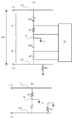
- FIG. 2A schematically shows a situation where a leakage occurs on the power transmission line in the leakage detection apparatus of FIG. (B) has shown the leak detection apparatus of the comparative example.
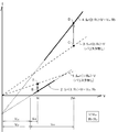
- FIG. 3 shows the VI characteristics showing the relationship between the voltage and current at one end of one resistance circuit during normal operation and electric leakage for each of the example of FIG. 2 (a) and the comparative example of FIG. 2 (b). It is a figure.
- FIG. 4 is a diagram showing another configuration example of the leakage detection apparatus of the present invention.
- FIG. 1 is a diagram showing an embodiment of the basic form of a leakage detection apparatus according to the present invention.
- the leakage detection device here means a circuit through which a bleeder current at normal time and a sensitivity current at the time of leakage flow. Circuits such as an earth leakage breaker that makes a leakage check using the sensitivity current and performs a power transmission interruption control are not included.
- the leakage detection device of the present invention is connected between a pair of power transmission lines L1 and L2 from a system power supply (not shown) which is an AC power supply, for example. In the case of three-phase alternating current, it is connected between each phase. Note that the present invention is not limited to an AC power supply and can also be applied to a DC power supply. In the case of a DC power supply, the positive and negative electrodes of the power transmission lines L1 and L2 can be arbitrarily set. Therefore, the leakage detection device of the present invention is connected in parallel to the power supply.
- the leakage detection device of the embodiment includes a first resistance circuit C1 and a second resistance circuit C2 connected in series between the power transmission lines L1 and L2.
- a varistor VR1 that is a constant voltage element and a resistance element R1 are connected in series.
- the resistance element R1 is a linear resistance element.
- the varistor VR2 which is a constant voltage element and the resistance element R2 are connected in series.
- the resistance element R2 is also a linear resistance element.
- the connection point N between the first resistor circuit C1 and the second resistor circuit C2 is grounded.
- the midpoint grounding method of the transmission line is known.
- the resistance values of the first resistor circuit C1 and the second resistor circuit C2 are preferably equal, but may not necessarily be equal if they are not significantly different.
- the relationship between the varistor VR1 and the varistor VR2 is the same, and the relationship between the resistance element R1 and the resistance element R2 is also the same.
- the varistor maintains a high resistance for a voltage below a certain varistor voltage and hardly passes current, but when a voltage exceeding the varistor voltage is applied, the resistance is reduced and the voltage at both ends is maintained at the varistor voltage.
- the varistor functions with respect to bidirectional current and is an element having a pressure resistance of several hundred volts, so it can be used for a high-voltage AC power supply.
- FIG. 2A shows a state where the potential of the power transmission line L1 is + Vi and the potential of the power transmission line L2 is ⁇ Vi on the power supply side in the embodiment of the leakage detection device of FIG. Therefore, the voltage between the power transmission line L1 and the power transmission line L2 is 2Vi.
- FIG. 2 (a) schematically shows a situation where a leakage occurs on the power transmission line L2 (the dotted line is the negative side where the leakage is present).
- the leakage point is indicated by the ground fault resistance Rs between the power transmission line L2 and the ground G.
- the resistance value of the ground fault resistance Rs is much smaller than the resistance values of the resistance circuits C1 and C2, or almost zero. In the following, it is set to zero for the sake of simplicity.
- the structure of the electrical leakage determination part 10 in a figure is arbitrary.
- the first resistance of the leakage detection device is obtained when the potentials of the transmission lines L1 and L2 are + Vi and ⁇ Vi.
- the voltage between both ends of the circuit C1 and the second resistance circuit C2 is Vi.
- FIG. 2B shows a leakage detection device of a comparative example.
- the comparative example there is no varistor between the power transmission lines L1 and L2, two linear resistance elements Ro are connected in series, and the connection point is grounded. Also in the comparative example, the voltage between both ends of each resistance element Ro at normal time is Vi.
- FIG. 3 shows the voltage V and the current I across the positive resistance circuit (first resistance circuit C1) during normal operation and electric leakage in each of the example of FIG. 2A and the comparative example of FIG.
- FIG. 6 is a diagram illustrating a VI characteristic indicating the relationship.
- the circuit of the embodiment functions when the voltage V across the first resistor circuit is larger than the varistor voltage Vvr (V> Vvr ).
- the set values are as follows. ⁇ Power supply voltage 2 Vi (Vi): 600 V (300 V) -Varistor voltage Vvr of varistor VR1: 200V -Resistance value R 1 of resistance element R 1 : 10 k ⁇ Resistance value of the resistor-element Ro R o: 20k ⁇
- the voltage across the first resistor circuit C1 is 2Vi during leakage, the voltage across V r1 of the resistor element R1 will 2Vi-V vr.
- the leakage detection device of the present invention in which the varistors VR1 and VR2 are inserted in series can reduce the resistance values of the resistance elements R1 and R2 and simultaneously the normal bleeder current as compared with the comparative example having no varistor. Can be reduced. Moreover, the sensitivity current at the time of electric leakage can be increased by reducing the resistance values of the resistance elements R1 and R2.
- FIG. 4 is a diagram illustrating an example of another embodiment of the leakage detection device of the present invention.
- the varistor of the first resistance circuit in the configuration of FIG. 1 is replaced with a pair of Zener diodes Z1 and Z2, and the varistor of the second resistance circuit is replaced with a pair of Zener diodes Z3 and Z4.
- each pair of Zener diodes is connected in series with opposite polarities. In the case of a DC power supply, it may be connected one by one in the opposite direction with respect to the polarity of the power supply voltage. Zener diodes are suitable for relatively low voltage power supplies.
- VR1 VR1, VR2 Constant voltage element (varistor) Z1, Z2, Z3, Z4 Constant voltage element (Zener diode) R1, R2 Resistance element C1, C2 Resistance circuit L1, L2 Power transmission line Rs Ground fault resistance G Grounding 10 Earth leakage determination unit
Landscapes
- Physics & Mathematics (AREA)
- General Physics & Mathematics (AREA)
- Engineering & Computer Science (AREA)
- Power Engineering (AREA)
- Testing Of Short-Circuits, Discontinuities, Leakage, Or Incorrect Line Connections (AREA)
- Emergency Protection Circuit Devices (AREA)
Abstract
Description
上記態様において、前記第1定電圧素子及び前記第2定電圧素子をそれぞれ、逆極性にて直列接続された2つのツェナーダイオードとすることができる。
上記態様において、前記第1定電圧素子及び前記第2定電圧素子をそれぞれツェナーダイオードとすることができる。
図1は、本発明による漏電検出装置の基本形態における一実施例を示した図である。ここでの漏電検出装置とは、正常時のブリーダ電流及び漏電時の感度電流が流れる回路を意味する。感度電流を用いて漏電判定を行ったり、送電の遮断制御を行ったりする漏電ブレーカ等の回路は含まないものとする。
次に、図2、図3を参照して図1の漏電検出装置の動作を説明する。
以下の動作説明は、交流電源の場合、各抵抗回路C1、C2に各バリスタのバリスタ電圧を超える所定の電圧が印加されている時点の状態と想定する。また、直流電源の場合も、電源電圧により各抵抗回路C1、C2に各バリスタのバリスタ電圧を超える所定の電圧が印加されていると想定する。すなわち、いずれの場合も、送電ラインL1、L2間には2つのバリスタのバリスタ電圧を加算した電圧を超える電圧が印加されていると想定する。これは、電源電圧に対して適切なバリスタ電圧を有するバリスタを選択することで実現できる。
正常時において、比較例の抵抗素子Roからなる正側の抵抗回路の両端電圧Vと電流Inoの関係は次のようになる。
Ino=(1/Ro)・V (1)
Ino:正常時の抵抗素子Roの電流
Ro :抵抗素子Roの抵抗値
式(1)は、図3のグラフでは直線1のように、傾き1/Roで原点を通る直線となる。V=Viのときの電流Inoは、点Aになる。
In=(1/R1)・V-Vvr/R1 (2)
In:正常時の抵抗素子R1の電流
R1:抵抗素子R1の抵抗値
Vvr:バリスタVR1のバリスタ電圧
式(2)は、図3のグラフでは直線2のようになる。
R1<Ro
とする。従って、直線2の傾き1/R1は、図示のように直線1の傾き1/Roよりも大きな傾きとなる。直線2は、バリスタ電圧Vvrに起因する定数項があるので、直線1のように原点を通る直線ではなく切片が負の直線となる。V=Viのときの電流Inは点Bになる。
Vr1=V-Vvr
の関係がある。正常時において第1抵抗回路C1の両端電圧がViのとき、抵抗素子R1の両端電圧Vr1は、Vi-Vvrになる。
・電源電圧2Vi(Vi) :600V(300V)
・バリスタVR1のバリスタ電圧Vvr :200V
・抵抗素子R1の抵抗値R1 :10kΩ
・抵抗素子Roの抵抗値Ro :20kΩ
この場合、正常時のブリーダ電流は、実施例ではIn=10mA、比較例ではIno=15mAとなり、実施例の方が小さくなる。
次に、図2(a)に示す漏電時においては、第2抵抗回路C2の両端電圧が零になるとすると、第1抵抗回路C1の両端電圧は2Viとなる。比較例についても同様に、正側の抵抗素子Roの両端電圧が2Viとなる。
Iso=(2/Ro)・V (3)
Iso:漏電時の抵抗素子Roの電流
Ro :抵抗素子Roの抵抗値
Is=(2/R1)・V-Vvr/R1 (4)
Is :漏電時の抵抗素子R1の電流
R1 :抵抗素子R1の抵抗値
Vvr:バリスタVR1のバリスタ電圧
Vr1=2V-Vvr
の関係がある。漏電時において第1抵抗回路C1の両端電圧が2Viのとき、抵抗素子R1の両端電圧Vr1は、2Vi-Vvrになる。
図4は、本発明の漏電検出装置の別の実施形態の例を示す図である。
図4に示す構成では、図1の構成における第1抵抗回路のバリスタが一対のツェナーダイオードZ1、Z2に置き換えられ、第2抵抗回路のバリスタが一対のツェナーダイオードZ3、Z4に置き換えられている。交流電源に対応するために、各対のツェナーダイオードは互いに逆極性で直列接続されている。なお、直流電源の場合は、電源電圧の極性に対して逆方向に1つずつ接続すればよい。ツェナーダイオードは比較的低電圧の電源の場合に適している。
Z1、Z2、Z3、Z4 定電圧素子(ツェナーダイオード)
R1、R2 抵抗素子
C1、C2 抵抗回路
L1、L2 送電ライン
Rs 地絡抵抗
G 接地
10 漏電判定部
Claims (4)
- 一対の送電ライン(L1、L2)間に接続される漏電検出装置において、
第1の線形抵抗素子(R1)と、所定の電圧を超える電圧印加に対して低抵抗化して両端間を定電圧に維持する第1の定電圧素子(VR1)とが直列接続された第1抵抗回路(C1)と、
第2の線形抵抗素子(R2)と、所定の電圧を超える電圧印加に対して低抵抗化して両端間を定電圧に維持する第2の定電圧素子(VR2)とが直列接続された第2抵抗回路(C2)と、を有し、
前記第1抵抗回路(C1)と前記第2抵抗回路(C2)が前記送電ライン(L1、L2)間に直列接続されており、かつ、前記第1抵抗回路(C1)と前記第2抵抗回路(C2)の接続点(N)が接地されていることを特徴とする漏電検出装置。 - 前記第1定電圧素子及び前記第2定電圧素子がそれぞれバリスタであることを特徴とする請求項1に記載の漏電検出装置。
- 前記第1定電圧素子及び前記第2定電圧素子がそれぞれ、逆極性にて直列接続された2つのツェナーダイオードであることを特徴とする請求項1に記載の漏電検出装置。
- 前記第1定電圧素子及び前記第2定電圧素子がそれぞれツェナーダイオードであることを特徴とする請求項1に記載の漏電検出装置。
Priority Applications (4)
| Application Number | Priority Date | Filing Date | Title |
|---|---|---|---|
| EP17766536.1A EP3432011B1 (en) | 2016-03-18 | 2017-03-09 | Electric leakage detection device |
| US16/086,237 US10746808B2 (en) | 2016-03-18 | 2017-03-09 | Electric leakage detection device |
| KR1020187022519A KR102325909B1 (ko) | 2016-03-18 | 2017-03-09 | 누전 검출 장치 |
| CN201780011994.9A CN109073696B (zh) | 2016-03-18 | 2017-03-09 | 漏电检测装置 |
Applications Claiming Priority (2)
| Application Number | Priority Date | Filing Date | Title |
|---|---|---|---|
| JP2016055920A JP6678051B2 (ja) | 2016-03-18 | 2016-03-18 | 漏電検出装置 |
| JP2016-055920 | 2016-03-18 |
Publications (1)
| Publication Number | Publication Date |
|---|---|
| WO2017159535A1 true WO2017159535A1 (ja) | 2017-09-21 |
Family
ID=59852245
Family Applications (1)
| Application Number | Title | Priority Date | Filing Date |
|---|---|---|---|
| PCT/JP2017/009474 Ceased WO2017159535A1 (ja) | 2016-03-18 | 2017-03-09 | 漏電検出装置 |
Country Status (6)
| Country | Link |
|---|---|
| US (1) | US10746808B2 (ja) |
| EP (1) | EP3432011B1 (ja) |
| JP (1) | JP6678051B2 (ja) |
| KR (1) | KR102325909B1 (ja) |
| CN (1) | CN109073696B (ja) |
| WO (1) | WO2017159535A1 (ja) |
Cited By (1)
| Publication number | Priority date | Publication date | Assignee | Title |
|---|---|---|---|---|
| JP7659789B1 (ja) | 2024-01-12 | 2025-04-10 | 株式会社ニプロン | 地絡検出器 |
Families Citing this family (5)
| Publication number | Priority date | Publication date | Assignee | Title |
|---|---|---|---|---|
| JP6678051B2 (ja) * | 2016-03-18 | 2020-04-08 | Ntn株式会社 | 漏電検出装置 |
| CN111366874B (zh) * | 2018-12-25 | 2025-04-08 | 兆易创新科技集团股份有限公司 | 漏电检测电路、闪存存储器漏电检测装置和漏电检测方法 |
| CN113820544B (zh) | 2021-10-11 | 2024-07-26 | 湖南小快智造电子科技有限公司 | 对地阻抗测量电路、对地阻抗测量方法 |
| DE102022002596A1 (de) * | 2022-07-18 | 2024-01-18 | Mercedes-Benz Group AG | Fahrzeug mit einem Hochvoltbordnetz und Verfahren zum Betrieb des Hochvoltbordnetzes |
| DE102023206991A1 (de) | 2023-07-24 | 2025-01-30 | Robert Bosch Gesellschaft mit beschränkter Haftung | Elektronische Schaltung zur Zustandsüberwachung spannungsabhängiger Widerstandsbauelemente |
Citations (6)
| Publication number | Priority date | Publication date | Assignee | Title |
|---|---|---|---|---|
| JPS50127630U (ja) * | 1974-04-02 | 1975-10-20 | ||
| JPS5649231Y2 (ja) * | 1975-07-25 | 1981-11-17 | ||
| JPH05275687A (ja) * | 1991-05-21 | 1993-10-22 | Shindengen Electric Mfg Co Ltd | プレ−ナ型二端子双方向性サイリスタ |
| JPH1188095A (ja) * | 1997-09-12 | 1999-03-30 | Jimbo Electric Co Ltd | ノイズ・フィルタ回路 |
| JP2013130536A (ja) * | 2011-12-22 | 2013-07-04 | Seiko Electric Co Ltd | 直流回路の地絡検出装置および方法 |
| JP2014522628A (ja) * | 2011-06-01 | 2014-09-04 | コミサリア ア レネルジ アトミク エ オウ エネルジ アルタナティヴ | 電力供給装置 |
Family Cites Families (18)
| Publication number | Priority date | Publication date | Assignee | Title |
|---|---|---|---|---|
| US3848159A (en) * | 1973-06-18 | 1974-11-12 | Airpax Electronics | Ground fault detector circuit with feedback to sensor |
| US3978400A (en) * | 1974-11-25 | 1976-08-31 | Square D Company | Ground fault detector with a nonlinear sensing means |
| JP3600211B2 (ja) * | 2000-02-22 | 2004-12-15 | 三洋電機株式会社 | 電源装置の漏電検出回路 |
| JP3594562B2 (ja) | 2001-03-30 | 2004-12-02 | 三洋電機株式会社 | 電源装置の漏電検出回路 |
| JP4053501B2 (ja) * | 2004-01-13 | 2008-02-27 | ファナック株式会社 | モータ駆動装置 |
| US7623329B2 (en) * | 2005-01-04 | 2009-11-24 | Technology Research Corporation | Leakage current detection and interruption circuit with improved shield |
| JP4994149B2 (ja) * | 2007-08-14 | 2012-08-08 | シチズンホールディングス株式会社 | 物理量センサ |
| US7791850B2 (en) * | 2008-01-16 | 2010-09-07 | Jingzheng Chen | Ground fault circuit interrupter control circuit |
| JP2009261039A (ja) | 2008-04-11 | 2009-11-05 | Ntt Data Intellilink Corp | 高圧直流給電接地回路及び高圧直流給電漏電遮断回路 |
| US8570181B2 (en) * | 2010-03-15 | 2013-10-29 | Siemens Industry, Inc. | Method and apparatus for supervisory circuit for ground fault circuit interrupt device |
| BRPI1003307A2 (pt) * | 2010-05-21 | 2012-02-07 | Furnas Centrais Elétricas S.A. | dispositivo, sistema e método para monitoramento de linhas de eletrodos de aterramento |
| US20120212864A1 (en) * | 2011-02-21 | 2012-08-23 | Elms Robert T | Fail-safe ground fault circuit interrupter |
| KR101247208B1 (ko) * | 2012-08-07 | 2013-03-26 | 엠티엔시 (주) | 누전 차단 장치 |
| US20140098446A1 (en) * | 2012-09-22 | 2014-04-10 | Victor V. Aromin | Universal Ground Fault Interrupter (GFCI) Device and Printed Circuit Board Package |
| ES2587785T3 (es) * | 2012-12-19 | 2016-10-26 | Littelfuse, Inc. | Interruptor de circuito de fallo de puesta a tierra |
| US9385489B2 (en) * | 2013-06-26 | 2016-07-05 | Calvin Wang | Adjustable electrical-power outlet strip |
| JP6678051B2 (ja) * | 2016-03-18 | 2020-04-08 | Ntn株式会社 | 漏電検出装置 |
| WO2018131797A1 (ko) * | 2017-01-11 | 2018-07-19 | 주식회사 나은에너지 | 배전계통 전원선로 고장시 실시간 탐지/복구시스템 및 그 공사방법 |
-
2016
- 2016-03-18 JP JP2016055920A patent/JP6678051B2/ja active Active
-
2017
- 2017-03-09 WO PCT/JP2017/009474 patent/WO2017159535A1/ja not_active Ceased
- 2017-03-09 KR KR1020187022519A patent/KR102325909B1/ko active Active
- 2017-03-09 CN CN201780011994.9A patent/CN109073696B/zh active Active
- 2017-03-09 EP EP17766536.1A patent/EP3432011B1/en active Active
- 2017-03-09 US US16/086,237 patent/US10746808B2/en active Active
Patent Citations (6)
| Publication number | Priority date | Publication date | Assignee | Title |
|---|---|---|---|---|
| JPS50127630U (ja) * | 1974-04-02 | 1975-10-20 | ||
| JPS5649231Y2 (ja) * | 1975-07-25 | 1981-11-17 | ||
| JPH05275687A (ja) * | 1991-05-21 | 1993-10-22 | Shindengen Electric Mfg Co Ltd | プレ−ナ型二端子双方向性サイリスタ |
| JPH1188095A (ja) * | 1997-09-12 | 1999-03-30 | Jimbo Electric Co Ltd | ノイズ・フィルタ回路 |
| JP2014522628A (ja) * | 2011-06-01 | 2014-09-04 | コミサリア ア レネルジ アトミク エ オウ エネルジ アルタナティヴ | 電力供給装置 |
| JP2013130536A (ja) * | 2011-12-22 | 2013-07-04 | Seiko Electric Co Ltd | 直流回路の地絡検出装置および方法 |
Non-Patent Citations (1)
| Title |
|---|
| See also references of EP3432011A4 * |
Cited By (2)
| Publication number | Priority date | Publication date | Assignee | Title |
|---|---|---|---|---|
| JP7659789B1 (ja) | 2024-01-12 | 2025-04-10 | 株式会社ニプロン | 地絡検出器 |
| JP2025109287A (ja) * | 2024-01-12 | 2025-07-25 | 株式会社ニプロン | 地絡検出器 |
Also Published As
| Publication number | Publication date |
|---|---|
| EP3432011A1 (en) | 2019-01-23 |
| CN109073696A (zh) | 2018-12-21 |
| US10746808B2 (en) | 2020-08-18 |
| EP3432011A4 (en) | 2019-12-04 |
| US20190162770A1 (en) | 2019-05-30 |
| CN109073696B (zh) | 2021-02-05 |
| KR102325909B1 (ko) | 2021-11-11 |
| KR20180122601A (ko) | 2018-11-13 |
| EP3432011B1 (en) | 2026-01-14 |
| JP6678051B2 (ja) | 2020-04-08 |
| JP2017172992A (ja) | 2017-09-28 |
Similar Documents
| Publication | Publication Date | Title |
|---|---|---|
| JP6678051B2 (ja) | 漏電検出装置 | |
| US6714393B2 (en) | Transient suppression apparatus for potentially explosive environments | |
| CN104515927B (zh) | 用于检测高电阻接地系统中的接地故障的检测器和方法 | |
| CN116540008A (zh) | 用于检测dc系统中的接地故障的系统和方法 | |
| JP2002296316A (ja) | 電源装置の漏電検出回路 | |
| US10508942B2 (en) | Thermal flow meter | |
| US10514307B2 (en) | Fault detection apparatus | |
| CN102057573B (zh) | 负载电路的过电流保护装置 | |
| US10345356B2 (en) | System and method for protection against electric shock | |
| JP7445894B2 (ja) | 漏電検出装置 | |
| CN108369252B (zh) | 电子设备 | |
| JP6862122B2 (ja) | 直流地絡検出器 | |
| JP5989171B1 (ja) | 電流検出回路、及びその回路を備えた車両用電子制御装置 | |
| WO2018092475A1 (ja) | 配線異常検出装置 | |
| JP2014202696A (ja) | 漏電検出方法 | |
| CN208797555U (zh) | 过电流保护电路 | |
| JP6239171B1 (ja) | 電力変換装置 | |
| JP7762902B2 (ja) | 直流電源の漏電検出装置 | |
| JP2021157929A (ja) | 異常検出装置 | |
| JP2009097914A (ja) | 漏電検出方法 | |
| JP2007218664A (ja) | 電流検出装置 | |
| KR101667218B1 (ko) | 이상 전압 보호장치, 발광 모듈 및 디스플레이 장치 | |
| JPH0225466B2 (ja) | ||
| JPH04347531A (ja) | 直流コンデンサの異常検出器 |
Legal Events
| Date | Code | Title | Description |
|---|---|---|---|
| ENP | Entry into the national phase |
Ref document number: 20187022519 Country of ref document: KR Kind code of ref document: A |
|
| NENP | Non-entry into the national phase |
Ref country code: DE |
|
| WWE | Wipo information: entry into national phase |
Ref document number: 2017766536 Country of ref document: EP |
|
| ENP | Entry into the national phase |
Ref document number: 2017766536 Country of ref document: EP Effective date: 20181018 |
|
| 121 | Ep: the epo has been informed by wipo that ep was designated in this application |
Ref document number: 17766536 Country of ref document: EP Kind code of ref document: A1 |
|
| WWG | Wipo information: grant in national office |
Ref document number: 2017766536 Country of ref document: EP |