WO2017159541A1 - Dispositif de support d'unité d'inspection et appareil d'inspection - Google Patents
Dispositif de support d'unité d'inspection et appareil d'inspection Download PDFInfo
- Publication number
- WO2017159541A1 WO2017159541A1 PCT/JP2017/009517 JP2017009517W WO2017159541A1 WO 2017159541 A1 WO2017159541 A1 WO 2017159541A1 JP 2017009517 W JP2017009517 W JP 2017009517W WO 2017159541 A1 WO2017159541 A1 WO 2017159541A1
- Authority
- WO
- WIPO (PCT)
- Prior art keywords
- inspection unit
- inspection
- unit
- support device
- packaging
- Prior art date
- Legal status (The legal status is an assumption and is not a legal conclusion. Google has not performed a legal analysis and makes no representation as to the accuracy of the status listed.)
- Ceased
Links
Images


Classifications
-
- B—PERFORMING OPERATIONS; TRANSPORTING
- B65—CONVEYING; PACKING; STORING; HANDLING THIN OR FILAMENTARY MATERIAL
- B65B—MACHINES, APPARATUS OR DEVICES FOR, OR METHODS OF, PACKAGING ARTICLES OR MATERIALS; UNPACKING
- B65B9/00—Enclosing successive articles, or quantities of material, e.g. liquids or semiliquids, in flat, folded, or tubular webs of flexible sheet material; Subdividing filled flexible tubes to form packages
- B65B9/10—Enclosing successive articles, or quantities of material, in preformed tubular webs, or in webs formed into tubes around filling nozzles, e.g. extruded tubular webs
- B65B9/20—Enclosing successive articles, or quantities of material, in preformed tubular webs, or in webs formed into tubes around filling nozzles, e.g. extruded tubular webs the webs being formed into tubes in situ around the filling nozzles
-
- B—PERFORMING OPERATIONS; TRANSPORTING
- B65—CONVEYING; PACKING; STORING; HANDLING THIN OR FILAMENTARY MATERIAL
- B65B—MACHINES, APPARATUS OR DEVICES FOR, OR METHODS OF, PACKAGING ARTICLES OR MATERIALS; UNPACKING
- B65B37/00—Supplying or feeding fluent-solid, plastic, or liquid material, or loose masses of small articles, to be packaged
- B65B37/16—Separating measured quantities from supply
- B65B37/18—Separating measured quantities from supply by weighing
-
- B—PERFORMING OPERATIONS; TRANSPORTING
- B65—CONVEYING; PACKING; STORING; HANDLING THIN OR FILAMENTARY MATERIAL
- B65B—MACHINES, APPARATUS OR DEVICES FOR, OR METHODS OF, PACKAGING ARTICLES OR MATERIALS; UNPACKING
- B65B5/00—Packaging individual articles in containers or receptacles, e.g. bags, sacks, boxes, cartons, cans, jars
- B65B5/06—Packaging groups of articles, the groups being treated as single articles
- B65B5/064—Potato chips
-
- B—PERFORMING OPERATIONS; TRANSPORTING
- B65—CONVEYING; PACKING; STORING; HANDLING THIN OR FILAMENTARY MATERIAL
- B65B—MACHINES, APPARATUS OR DEVICES FOR, OR METHODS OF, PACKAGING ARTICLES OR MATERIALS; UNPACKING
- B65B5/00—Packaging individual articles in containers or receptacles, e.g. bags, sacks, boxes, cartons, cans, jars
- B65B5/10—Filling containers or receptacles progressively or in stages by introducing successive articles, or layers of articles
- B65B5/101—Filling containers or receptacles progressively or in stages by introducing successive articles, or layers of articles by gravity
-
- B—PERFORMING OPERATIONS; TRANSPORTING
- B65—CONVEYING; PACKING; STORING; HANDLING THIN OR FILAMENTARY MATERIAL
- B65B—MACHINES, APPARATUS OR DEVICES FOR, OR METHODS OF, PACKAGING ARTICLES OR MATERIALS; UNPACKING
- B65B51/00—Devices for, or methods of, sealing or securing package folds or closures; Devices for gathering or twisting wrappers, or necks of bags
- B65B51/10—Applying or generating heat or pressure or combinations thereof
- B65B51/14—Applying or generating heat or pressure or combinations thereof by reciprocating or oscillating members
- B65B51/146—Closing bags
-
- B—PERFORMING OPERATIONS; TRANSPORTING
- B65—CONVEYING; PACKING; STORING; HANDLING THIN OR FILAMENTARY MATERIAL
- B65B—MACHINES, APPARATUS OR DEVICES FOR, OR METHODS OF, PACKAGING ARTICLES OR MATERIALS; UNPACKING
- B65B51/00—Devices for, or methods of, sealing or securing package folds or closures; Devices for gathering or twisting wrappers, or necks of bags
- B65B51/10—Applying or generating heat or pressure or combinations thereof
- B65B51/26—Devices specially adapted for producing transverse or longitudinal seams in webs or tubes
- B65B51/30—Devices, e.g. jaws, for applying pressure and heat, e.g. for subdividing filled tubes
-
- B—PERFORMING OPERATIONS; TRANSPORTING
- B65—CONVEYING; PACKING; STORING; HANDLING THIN OR FILAMENTARY MATERIAL
- B65B—MACHINES, APPARATUS OR DEVICES FOR, OR METHODS OF, PACKAGING ARTICLES OR MATERIALS; UNPACKING
- B65B57/00—Automatic control, checking, warning, or safety devices
- B65B57/005—Safety-devices
-
- B—PERFORMING OPERATIONS; TRANSPORTING
- B65—CONVEYING; PACKING; STORING; HANDLING THIN OR FILAMENTARY MATERIAL
- B65B—MACHINES, APPARATUS OR DEVICES FOR, OR METHODS OF, PACKAGING ARTICLES OR MATERIALS; UNPACKING
- B65B57/00—Automatic control, checking, warning, or safety devices
- B65B57/10—Automatic control, checking, warning, or safety devices responsive to absence, presence, abnormal feed, or misplacement of articles or materials to be packaged
- B65B57/16—Automatic control, checking, warning, or safety devices responsive to absence, presence, abnormal feed, or misplacement of articles or materials to be packaged and operating to stop, or to control the speed of, the machine as a whole
-
- B—PERFORMING OPERATIONS; TRANSPORTING
- B65—CONVEYING; PACKING; STORING; HANDLING THIN OR FILAMENTARY MATERIAL
- B65B—MACHINES, APPARATUS OR DEVICES FOR, OR METHODS OF, PACKAGING ARTICLES OR MATERIALS; UNPACKING
- B65B59/00—Arrangements to enable machines to handle articles of different sizes, to produce packages of different sizes, to vary the contents of packages, to handle different types of packaging material, or to give access for cleaning or maintenance purposes
- B65B59/04—Machines constructed with readily-detachable units or assemblies, e.g. to facilitate maintenance
-
- G—PHYSICS
- G01—MEASURING; TESTING
- G01G—WEIGHING
- G01G19/00—Weighing apparatus or methods adapted for special purposes not provided for in the preceding groups
- G01G19/387—Weighing apparatus or methods adapted for special purposes not provided for in the preceding groups for combinatorial weighing, i.e. selecting a combination of articles whose total weight or number is closest to a desired value
-
- G—PHYSICS
- G01—MEASURING; TESTING
- G01V—GEOPHYSICS; GRAVITATIONAL MEASUREMENTS; DETECTING MASSES OR OBJECTS; TAGS
- G01V3/00—Electric or magnetic prospecting or detecting; Measuring magnetic field characteristics of the earth, e.g. declination, deviation
- G01V3/08—Electric or magnetic prospecting or detecting; Measuring magnetic field characteristics of the earth, e.g. declination, deviation operating with magnetic or electric fields produced or modified by objects or geological structures or by detecting devices
- G01V3/10—Electric or magnetic prospecting or detecting; Measuring magnetic field characteristics of the earth, e.g. declination, deviation operating with magnetic or electric fields produced or modified by objects or geological structures or by detecting devices using induction coils
Definitions
- the present invention provides an inspection unit support device that supports an inspection unit having a cylindrical member that passes an article falling from above and guides the article downward, and an inspection unit that inspects the article that passes through the cylindrical member, and And an inspection apparatus including the same.
- a weighing and packaging system including a combination weighing device and a bag making and packaging device has been used.
- the combination weighing device subdivides the articles into a plurality of weighing hoppers, selects a combination of the weighing hoppers so that the total mass of the divided articles falls within a predetermined range, and discharges the articles downward from the weighing hoppers.
- the bag-making and packaging device performs horizontal sealing on the lower end of the tube-shaped packaging material, and then inserts the article discharged from the weighing hopper into the packaging material to horizontally seal the upper end of the packaging material.
- a bag in which the article is enclosed is manufactured.
- Patent Document 1 Japanese Patent Laid-Open No. Sho 63-148130
- Patent Document 2 Japanese Patent Publication No. 2014-511484
- a system is disclosed in which a metal detector for detecting metal foreign matter mixed in an article is disposed between a bag making and packaging apparatus and a combination weighing apparatus.
- a chute is disposed between the bag making and packaging device and the combination weighing device for passing the articles discharged from the combination weighing device to the input port of the bag making and packaging device.
- the chute is a resin-made and cylindrical member attached to the metal detector. The chute is removed from the metal detector and cleaned when the production of the article is finished and when the seasoning used for seasoning the article, which is a food, is changed.
- the chute attaching / detaching operation is often a dangerous operation using a step board or the like.
- the attaching / detaching operation of the chute requires the removal of the former (a member serving as an input port for the article) of the bag making and packaging apparatus disposed below the chute, which is often a complicated operation. Therefore, there is a need for a mechanism that allows the chute to be easily detached from the metal detector.
- An object of the present invention is to provide an inspection unit support device having a mechanism that allows a cylindrical member that guides an article from above to below to be easily detached from the inspection unit, and an inspection device including the same.
- the inspection unit support device supports the inspection unit.
- the inspection unit includes a cylindrical member and an inspection device.
- the cylindrical member passes the article falling from above and guides the article downward.
- the inspection device inspects an article passing through the cylindrical member.
- the inspection unit support device includes a first member and a second member.
- the first member is a member to which the inspection unit is fixed.
- the second member is a member that supports the first member so that the first member can move along the horizontal direction.
- This inspection unit support device is used, for example, in a weighing and packaging system including a combination weighing device and a bag making and packaging device.
- the inspection unit supported by the inspection unit support device includes a cylindrical member that guides an article discharged from the combination weighing device to the bag making and packaging apparatus, and an inspection device that inspects the article that passes through the cylindrical member.
- An operator can slide the inspection unit in the horizontal direction before removing the tube member from the inspection unit (inspector) in order to clean the tube member.
- the operator can easily access the inspection unit by bringing the inspection unit closer to him / her, so that the cylinder member can be easily detached from the inspection unit. Therefore, this inspection unit support device can improve the accessibility to the inspection unit.
- the second member is preferably configured such that at least a part of the inspection unit can move downward after the first member moves in the horizontal direction.
- this inspection unit support device the operator can lower a part of the inspection unit so that the inspection unit comes close to him after sliding the inspection unit in the horizontal direction. Therefore, this inspection unit support device can improve the accessibility and visibility to the inspection unit.
- the second member is configured such that the inspection unit is inclined after the first member moves in the horizontal direction.
- this inspection unit support device the operator can tilt the inspection unit with respect to the operator after sliding the inspection unit in the horizontal direction. Therefore, this inspection unit support device can improve the accessibility and visibility to the inspection unit.
- the second member supports the first member so that the first member can move downward while being inclined after the first member moves in the horizontal direction.
- this inspection unit support apparatus the operator can slide down the inspection unit in a horizontal direction and then lower a part of the inspection unit so as to approach the user while tilting the inspection unit. Therefore, this inspection unit support device can improve the accessibility and visibility to the inspection unit.
- the second member preferably has a pair of horizontal portions and an inclined portion.
- the pair of horizontal portions support the first member so as to be movable in the horizontal direction.
- the inclined portion is connected to one of the pair of horizontal portions and supports the first member together with the other of the pair of horizontal portions, thereby supporting the first member so as to be movable while being inclined.
- the first member fixes the inspection unit between the pair of horizontal portions.
- the inspection unit support device includes a second member for moving the inspection unit attached to the first member.
- the second member limits the movement of the inspection unit. Therefore, this inspection unit support device can ensure the safety of the operator accompanying the movement of the inspection unit.
- An inspection apparatus includes the above-described inspection unit support device and an inspection unit supported by the inspection unit support device.
- the inspection unit includes a cylindrical member and an inspection device.
- the cylindrical member passes the article falling from above and guides the article downward.
- the inspection device inspects an article passing through the cylindrical member.
- the cylinder member is detachable from the inspection device.
- the operator can easily clean the cylindrical member with the cylindrical member that is detachable from the inspection device.
- the inspection unit support device and the inspection device including the same have a mechanism that allows a cylindrical member that guides an article from above to below to be easily detached from the inspection unit.
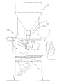
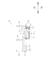
- FIG. 1 is a side view of a weighing packaging system 100.
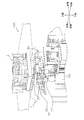
- FIG. 1 is a front view showing a schematic configuration of a weighing packaging system 100.
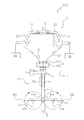
- FIG. 2 is a perspective view showing a schematic configuration of a bag making and packaging unit 3.
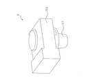
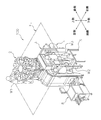
- FIG. 4 is a perspective view of an inspection unit 9.
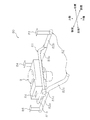
- FIG. It is a perspective view of the test
- FIG. 10 is a top view of the inspection unit support device 80 shown in FIG. 9.
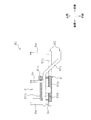
- FIG. 11 is a side view of the inspection unit support device 80 as viewed from the direction of arrow XI in FIG. 10.
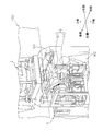
- 2 is a diagram illustrating an operator who performs maintenance work of the weighing and packaging system 100.
- FIG. It is a figure showing worker W2 who is carrying out the work which removes inspection chute 91 from inspection unit 9.
- FIG. 14 is a view of FIG. 13 viewed from another angle. 4 is a top view of an inspection chute 91.
- FIG. FIG. 16 is a side view of the inspection chute 91 as viewed from the arrow XVI in FIG. 15.
- FIG. 1 is a perspective view of a weighing and packaging system 100 that is an embodiment of the present invention.
- FIG. 2 is a side view of the weighing and packaging system 100.
- FIG. 3 is a front view showing a schematic configuration of the weighing and packaging system 100.
- the weighing and packaging system 100 mainly includes a combination weighing unit 2, a bag making and packaging unit 3, an inspection unit 9, a film supply unit 4, an operation switch 5, a liquid crystal display 6, and a control unit (not shown). Is provided.
- the combination weighing unit 2 measures a predetermined amount of the packaged item C by combination weighing.
- the package C is a light and brittle food such as potato chips.
- the combination weighing unit 2 discharges the measured packaging object C downward and supplies it to the bag making and packaging unit 3. The detailed configuration and operation of the combination weighing unit 2 will be described later.
- the bag making and packaging unit 3 is disposed below the combination weighing unit 2.
- the bag making and packaging unit 3 wraps the supplied packaging material C with the film F in accordance with the timing when the packaging material C is supplied from the combination weighing unit 2.
- the film F is a sheet-like thin packaging material.
- the bag making and packaging unit 3 manufactures the bag B in which the article to be packaged C is sealed. The detailed configuration and operation of the bag making and packaging unit 3 will be described later.
- the inspection unit 9 is disposed between the combination weighing unit 2 and the bag making and packaging unit 3. That is, the inspection unit 9 is located below the combination weighing unit 2 and above the bag making and packaging unit 3.
- the inspection unit 9 inspects whether foreign matter is mixed in the packaged goods C discharged from the combination weighing unit 2.
- the inspection unit 9 inspects the article C to be packaged discharged from the combination weighing unit 2 and dropping it in a non-contact manner.
- the article C to be packaged is discharged from the combination weighing unit 2, passes through the inspection unit 9, and is supplied to the bag making and packaging unit 3.
- the foreign matter is a metal object that is mixed into the package C for some reason.
- the detailed configuration and operation of the inspection unit 9 will be described later.
- the film supply unit 4 is installed adjacent to the bag making and packaging unit 3.
- the film supply unit 4 supplies the film F to the bag making and packaging unit 3.
- a film roll 4 a around which the film F is wound is set in the film supply unit 4.
- the film supply unit 4 unwinds the film F from the film roll 4 a and supplies it to the bag making and packaging unit 3.
- the operation switch 5 and the liquid crystal display 6 are attached to the front surface of the main body of the bag making and packaging unit 3.
- the liquid crystal display 6 is a touch panel display disposed at a position where the operator of the operation switch 5 can visually recognize.
- the operation switch 5 and the liquid crystal display 6 function as an input device that receives commands and settings for the combination weighing unit 2, the bag making and packaging unit 3, the inspection unit 9, and the film supply unit 4.
- the liquid crystal display 6 functions as an output device that displays information regarding the combination weighing unit 2, the bag making and packaging unit 3, the inspection unit 9, and the film supply unit 4.
- the control unit is a computer composed of a CPU, ROM, RAM, and the like.
- the control unit is built in the bag making and packaging unit 3, for example.
- the control unit is connected to the combination weighing unit 2, bag making and packaging unit 3, inspection unit 9, film supply unit 4, operation switch 5, and liquid crystal display 6.
- the control unit controls the combination weighing unit 2, the bag making and packaging unit 3, the inspection unit 9 and the film supply unit 4 based on inputs from the operation switch 5 and the liquid crystal display 6, and outputs various information to the liquid crystal display 6. To do.
- the combination weighing unit 2 is a weighing machine for measuring a predetermined amount of the object to be packaged C.
- the article to be packaged C weighed and discharged by the combination weighing unit 2 passes through the inspection unit 9 and is supplied to the bag making and packaging unit 3.
- the combination weighing unit 2 mainly includes a dispersion feeder 21, a plurality of troughs 22, a plurality of pool hoppers 23, a plurality of weighing hoppers 24, a collecting chute 25, and a plurality of mass sensors 26.
- the object to be packaged C to be weighed When the object to be packaged C to be weighed is supplied to the combination weighing unit 2, the object to be packaged C drops near the center of the dispersion feeder 21. As shown in FIG. 3, a plurality of troughs 22 are provided on the periphery of the dispersion feeder 21. The dispersion feeder 21 and the trough 22 are given vibrations from a vibrating device (not shown). Thereby, as shown by the arrows in FIG. 3, the articles to be packaged C supplied to the dispersion feeder 21 fall through the troughs 22 and are stored in the pool hoppers 23 corresponding to the troughs 22.
- Each pool hopper 23 is disposed above the corresponding weighing hopper 24.
- the pool hopper 23 temporarily stores the articles C to be supplied to the corresponding weighing hoppers 24.
- Each weighing hopper 24 has a mass sensor 26.
- the mass sensor 26 outputs a load signal corresponding to the mass of the article C to be packaged supplied to the corresponding weighing hopper 24.
- the mass sensor 26 is, for example, a load cell.
- the combination weighing of the article C to be packaged by the combination weighing unit 2 is performed according to the following procedure.
- the mass sensor 26 detects the mass of the articles to be packaged C stored in the weighing hoppers 24.
- the combination closest to the desired value is obtained by calculation.
- the desired value is the mass of a predetermined amount of the article to be packaged C supplied to the bag making and packaging unit 3.
- the article to be packaged C is discharged from the weighing hopper 24 corresponding to the obtained combination to the cylindrical collecting chute 25.
- the articles C to be packaged discharged to the collecting chute 25 fall inside the collecting chute 25, and then pass through the inspection unit 9 to be supplied to the bag making and packaging unit 3.
- the combination weighing is again performed in which a predetermined amount of the packaged object C is measured.
- FIG. 4 is a perspective view showing a schematic configuration of the bag making and packaging unit 3.
- six directions consisting of “front (front)”, “rear (back)”, “up”, “down”, “left” and “right” are defined as shown in FIG. .
- FIG. 3 is a view of the bag making and packaging unit 3 shown in FIG. 4 as viewed in the left-right direction.
- the bag making and packaging unit 3 mainly includes a forming mechanism 13, a pull-down belt mechanism 14, a vertical sealing mechanism 15, and a horizontal sealing mechanism 16.
- the forming mechanism 13 forms the sheet-like film F supplied from the film supply unit 4 into a cylindrical shape.
- the pull-down belt mechanism 14 conveys the film F formed into a cylindrical shape downward.
- the vertical sealing mechanism 15 seals the overlapping portion of both end portions of the film F formed into a cylindrical shape in the vertical direction parallel to the transport direction to form the cylindrical film Fc.
- the horizontal sealing mechanism 16 seals the cylindrical film Fc at two locations in the horizontal direction orthogonal to the transport direction, and forms a bag B in which the upper end and the lower end are horizontally sealed.
- the forming mechanism 13 includes a tube 13a and a former 13b.
- the tube 13a is a cylindrical member whose upper end and lower end are open.
- An article C to be packaged supplied from the combination weighing unit 2 is put into the opening at the upper end of the tube 13a.
- the former 13b is disposed so as to surround the tube 13a.
- the film F fed out from the film roll of the film supply unit 4 passes through the gap between the tube 13a and the former 13b, the film F is wound around the tube 13a and formed into a cylindrical shape.
- the tube 13a and the former 13b can be replaced according to the size of the bag B to be manufactured.
- the pull-down belt mechanism 14 conveys the film F wound around the tube 13a downward while adsorbing it.
- the pull-down belt mechanism 14 mainly includes a driving roller 14a, a driven roller 14b, and a pair of belts 14c. As shown in FIG. 4, the pair of belts 14c are arranged so as to sandwich the tube 13a on both the left and right sides of the tube 13a, and have a mechanism for adsorbing the film F formed into a cylindrical shape.
- the pull-down belt mechanism 14 conveys the film F formed into a cylindrical shape downward by rotating the pair of belts 14c by the driving roller 14a and the driven roller 14b.
- the vertical seal mechanism 15 seals the film F formed in a cylindrical shape in the vertical direction (vertical direction in FIG. 4).
- the vertical seal mechanism 15 is disposed on the front side of the tube 13a.
- the vertical seal mechanism 15 is moved in the front-rear direction so as to approach the tube 13a or away from the tube 13a by a drive mechanism (not shown).
- the vertical sealing mechanism 15 heats the overlapping portion of the film F in the vertical direction by heating the overlapping portion of the film F against the tube 13a with a constant pressure by the driving mechanism, thereby forming the tubular film Fc.
- the vertical sealing mechanism 15 includes a heater that heats the overlapping portion of the film F, a heater belt that contacts the overlapping portion of the film F, and the like.
- the horizontal sealing mechanism 16 is conveyed downward by a pair of sealing jaws 51 (sealing jaw 51a and sealing jaw 51b) or a pair of sealing jaws 52 (sealing jaw 52a and sealing jaw 52b). This is a mechanism for sandwiching a sealed portion of the tubular film Fc that is to be sealed along a direction (left-right direction in FIG. 4) intersecting the conveyance direction of the tubular film Fc and laterally sealing.
- Each of the sealing jaw 51a and the sealing jaw 51b has a sealing surface that comes into contact with the tubular film Fc when the tubular film Fc is sandwiched.
- the tubular film Fc conveyed downward is sandwiched between the sealing surface of the sealing jaw 51a and the sealing surface of the sealing jaw 51b and is pressurized.
- the seal jaw 51a and the seal jaw 51b have heaters inside.
- the sealing surfaces of the sealing jaws 51a and 51b are heated by this heater.
- the sealing surface is heated in a state where the tubular film Fc is sandwiched between the pair of sealing jaws 51a and 51b, the sealed portion of the tubular film Fc is heat sealed.
- the tubular film Fc conveyed downward is heat-sealed in order from the downstream side (front side in the conveyance direction) to the upstream side (rear side in the conveyance direction), and the bag B is continuously formed.
- a cutter (not shown) for separating the bag B from the tubular film Fc is attached to the seal jaw 51b near the center of the seal surface in the short direction (vertical direction in FIG. 4). This cutter is attached so that the blade edge protrudes toward the sealing jaw 51a side during the horizontal sealing operation by the pair of sealing jaws 51a and 51b.
- a groove (not shown) that engages with the cutter protruding from the seal jaw 51b is formed near the center of the seal surface in the short direction (vertical direction in FIG. 4).
- the cutter cuts the heat-sealed portion of the tubular film Fc from one end side to the other end side in the lateral sealing direction (left-right direction), and separates the bag B from the tubular film Fc.
- FIG. 5 is a perspective view of the inspection unit 9.
- the inspection unit 9 mainly includes an inspection chute 91 and a metal detector 92.
- the inspection unit 9 is supported by an inspection unit support device 80.
- the inspection chute 91 is a cylindrical member made of resin.
- the inspection chute 91 has a tapered shape whose diameter gradually decreases from the upper side to the lower side. As shown in FIG. 3, the articles C to be packaged discharged from the collective chute 25 of the combination weighing unit 2 pass through the inspection chute 91 while dropping, and enter the tube 13 a of the bag making and packaging unit 3. It is thrown.
- the metal detector 92 is a device that detects a metallic foreign matter mixed in the package C passing through the inspection chute 91. As shown in FIG. 5, the metal detector 92 has a hole through which the inspection chute 91 passes.
- the inspection chute 91 is detachable from the inspection unit 9 (metal detector 92). That is, an operator in charge of maintenance of the weighing and packaging system 100 can remove the inspection chute 91 from the metal detector 92 and attach the inspection chute 91 to the metal detector 92.
- FIG. 6 is a perspective view of the inspection unit support device 80.
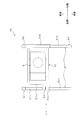
- FIG. 7 is a top view of the inspection unit support device 80 shown in FIG.
- FIG. 8 is a side view of the inspection unit support device 80 viewed from the direction of the arrow VIII in FIG. 6 to 8, the inspection unit 9 is in a position when the weighing and packaging system 100 is in operation (hereinafter referred to as “operation position”).
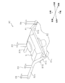
- FIG. 9 is a perspective view of the inspection unit support device 80.
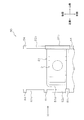
- FIG. 10 is a top view of the inspection unit support device 80 shown in FIG.
- FIG. 11 is a side view of the inspection unit support device 80 viewed from the direction of the arrow XI in FIG. 9 to 11, the inspection unit 9 is in a position where maintenance work of the weighing and packaging system 100 is being performed (hereinafter referred to as “work position”).
- the maintenance work of the weighing packaging system 100 is, for example, cleaning of the inspection chute 91 and replacement of the inspection chute 91.
- the inspection unit support device 80 mainly includes a fixed frame 81 and a guide frame 82.
- the fixed frame 81 is shown as a hatched area for easy understanding.
- the fixed frame 81 is a member to which the inspection unit 9 is fixed. Usually, the inspection unit 9 is not removed from the fixed frame 81. While the weighing packaging system 100 is operating, the inspection unit 9 is in the operating position, and the position of the fixed frame 81 is not changed. On the other hand, when performing maintenance work of the weighing and packaging system 100, the position of the fixed frame 81 is changed because the inspection unit 9 needs to be moved from the operating position to the working position. Therefore, the fixed frame 81 is movable in a predetermined direction. However, as will be described later, the movement of the fixed frame 81 is restricted by the guide frame 82.
- the guide frame 82 is a member that supports the fixed frame 81.
- the guide frame 82 is fixed to the main body of the bag making and packaging unit 3.
- the guide frame 82 supports the fixed frame 81 so that the fixed frame 81 can move along the horizontal direction. Further, the guide frame 82 is configured such that after the fixed frame 81 moves along the horizontal direction, the inspection unit 9 fixed to the fixed frame 81 is inclined so that at least a part of the inspection unit 9 can move downward. Further, the fixed frame 81 is supported.
- the guide frame 82 mainly includes a pair of horizontal rails 82a and 82b and an inclined rail 82c.
- the pair of horizontal rails 82a and 82b and the inclined rail 82c extend along the front-rear direction.
- the pair of horizontal rails 82a and 82b includes a first horizontal rail 82a located on the left side and a second horizontal rail 82b located on the right side.
- the pair of horizontal rails 82a and 82b are arranged in the horizontal direction and parallel to each other.
- the inclined rail 82c is connected to the front end of the first horizontal rail 82a.
- the inclined rail 82c has a portion that is inclined so as to descend from the rear side toward the front side.
- the front end of the inclined rail 82c is along the horizontal direction. As shown in FIGS. 7 and 10, when the guide frame 82 is viewed along the vertical direction, the inclined rail 82c is parallel to the pair of horizontal rails 82a and 82b.
- the pair of horizontal rails 82a and 82b support the fixed frame 81 so as to be movable in the front-rear direction.
- the inclined rail 82c supports the fixed frame 81 together with the second horizontal rail 82b.
- the inclined rail 82c supports the fixed frame 81 so as to be movable in the front-rear direction while inclining the fixed frame 81.
- a connecting portion 84 is connected in the vicinity of both end portions of the first horizontal rail 82a and the second horizontal rail 82b.
- the connecting portion 84 is a member that extends upward.
- the upper end portion of the connecting portion 84 is fixed to the main body of the bag making and packaging unit 3.
- the fixed frame 81 mainly includes a fixed portion 81a, a slide portion 81b, and a handle portion 81c.
- the fixing portion 81a is a member for fixing the inspection unit 9 between the pair of horizontal rails 82a and 82b.
- the slide part 81b is a tubular member connected to the right side of the fixed part 81a.
- the second horizontal rail 82b passes through the inside of the slide portion 81b.
- the slide part 81b is slidable with respect to the second horizontal rail 82b.
- the handle portion 81c is a member connected to the left side of the fixed portion 81a.
- the handle portion 81c is supported by the first horizontal rail 82a or the inclined rail 82c.
- the handle part 81c is located in front of the connecting part 84 connected to the first horizontal rail 82a.
- the slide part 81b is located between the pair of connecting parts 84 of the second horizontal rail 82b. Therefore, normally, the slide part 81b cannot be removed from the second horizontal rail 82b. That is, normally, the fixed frame 81 cannot be removed from the guide frame 82.
- the inspection unit 9 having the fixed frame 81 is movable in the front-rear direction.
- the movable range of the slide portion 81b is limited by the pair of connecting portions 84 of the second horizontal rail 82b. Therefore, the movement range of the inspection unit 9 is similarly limited.
- the operator can pull out the inspection unit 9 from the operating position to the front side as shown in FIGS. 9 to 11 when the weighing and packaging system 100 is not operating. Specifically, the operator can move the inspection unit 9 to the work position by holding the handle portion 81c of the fixed frame 81 to which the inspection unit 9 in the operating position is fixed and pulling it toward the front side. . On the contrary, the operator can move the inspection unit 9 to the operating position by holding the handle portion 81c of the fixed frame 81 of the inspection unit 9 in the working position and pushing it out toward the rear side.
- the inspection unit 9 is inclined so as to descend from the right side toward the left side.
- the fixed frame 81 moves in the horizontal direction (front-rear direction) while being supported by the pair of horizontal rails 82a and 82b.
- the fixed frame 81 moves in the horizontal direction (front-rear direction) while being supported by the inclined rail 82c and the second horizontal rail 82b.
- the handle portion 81c of the fixed frame 81 moves along the inclined rail 82c
- the fixed portion 81a of the fixed frame 81 is inclined. Therefore, the inspection unit 9 fixed to the fixing portion 81a is similarly inclined. Therefore, in the process in which the inspection unit 9 moves from the operating position to the work position, the inspection unit 9 moves downward while tilting. As the inspection unit 9 moves downward, the inclination angle of the inspection unit 9 gradually increases. On the contrary, in the process in which the inspection unit 9 moves from the working position to the operating position, the inclined inspection unit 9 gradually becomes horizontal.
- the control unit is connected to each component of the combination weighing unit 2 and constitutes a part of the combination weighing unit 2 as a control unit of the combination weighing unit 2.
- the control unit is connected to each component of the bag making and packaging unit 3 (mainly, the pull-down belt mechanism 14, the vertical seal mechanism 15, and the horizontal seal mechanism 16). Therefore, the control unit constitutes a part of the bag making and packaging unit 3 as a control unit of the bag making and packaging unit 3.
- the control unit controls the combination weighing unit 2 and the bag making and packaging unit 3 by executing the stored program. For example, the control unit controls the combination weighing unit 2 and the bag making and packaging unit 3 so that the combination weighing unit 2 and the bag making and packaging unit 3 perform the following operations.
- the mass of the article to be packaged C is weighed by the plurality of weighing hoppers 24 and combined so that the weighing value becomes a predetermined total mass. Discharged.
- the control unit controls the combination weighing unit 2 so that these series of operations are performed.
- the article C to be packaged discharged from the combination weighing unit 2 is dropped onto the upper opening end of the tube 13a of the bag making and packaging unit 3.
- the control unit controls the film supply unit 4 as a control unit for controlling the bag making and packaging unit 3 so that the film F is supplied to the forming mechanism 13.
- the control unit controls the pull-down belt mechanism 14 as a control unit for controlling the bag making and packaging unit 3 so that the film F (cylindrical film Fc) formed into a cylindrical shape by the forming mechanism 13 is conveyed downward.
- Control controls the vertical sealing mechanism 15 as a control unit for controlling the bag making and packaging unit 3 so that overlapping portions of both end portions of the tubular film Fc conveyed downward are sealed in the vertical direction. .
- a control unit is a control part which controls the bag making packaging unit 3, and goes below according to the timing to which the to-be-packaged goods C discharged
- the horizontal sealing mechanism 16 is controlled so that the transported tubular film Fc is sealed in the lateral direction and the sealed bag B is separated from the upstream tubular film Fc.
- the weighing packaging system 100 includes the inspection unit 9 supported by the inspection unit support device 80.
- the inspection unit 9 includes an inspection chute 91 and a metal detector 92.
- the inspection chute 91 is a resin cylindrical member that guides the article C to be packaged discharged from the combination weighing unit 2 to the bag making and packaging unit 3.
- the metal detector 92 is a device that detects metallic foreign matter mixed in the packaged article C that passes through the inspection chute 91.
- the inspection chute 91 is attached to the metal detector 92.
- the inspection chute 91 is removed from the metal detector 92 and cleaned when the production of the article C to be packaged is finished and when the seasoning used for seasoning the article C to be packaged is changed. .
- FIG. 12 is a diagram showing an operator who performs maintenance work of the weighing and packaging system 100.
- FIG. 12 shows a combination weighing unit 2, a bag making and packaging unit 3, a film supply unit 4, and a bag transport unit 8.
- the bag transport unit 8 is an apparatus independent of the weighing and packaging system 100.
- the bag transport unit 8 includes a belt conveyor for transporting the bag B manufactured by the weighing and packaging system 100 to a predetermined place.
- FIG. 12 shows workers W1, W2, and W3.
- the worker W1 is performing maintenance work on the combination weighing unit 2 on the work floor FL.
- the operator W2 is performing maintenance work on the inspection unit 9 inside the main body of the bag making and packaging unit 3.
- the worker W ⁇ b> 2 stands on the right side of the inspection unit 9 and performs maintenance work on the inspection unit 9.
- the operator W3 operates the operation panel of the weighing and packaging system 100 on the platform S.
- the inspection unit 9 is located between the combination weighing unit 2 and the bag making and packaging unit 3, and is usually arranged at a position higher than the worker W2.
- the worker W2 needs to remove the inspection chute 91 from the inspection unit 9 (metal detector 92) before cleaning the inspection chute 91.
- an operator has to remove the inspection chute from the metal detector by using a platform or the like in order to access the metal detector located higher than the worker. Therefore, the work of removing the inspection chute from the metal detector is an unstable and dangerous work at a high place.
- the bag transport unit 8 is installed on the front side (front side) of the bag making and packaging unit 3, it is difficult to install a step board or the like in the vicinity of the inspection unit 9.
- FIG. 13 is a diagram illustrating the worker W2 who is performing the work of removing the inspection chute 91 from the inspection unit 9.
- FIG. 14 is a view of FIG. 13 viewed from another angle. 13 and 14, the movement direction of the inspection unit 9 when the worker W2 pulls out the inspection unit 9 from the operating position to the work position is indicated by an arrow.
- the inspection unit support device 80 includes a fixed frame 81 to which the inspection unit 9 is fixed, and a guide frame 82 that guides the fixed frame 81.
- the operator W2 can bring the inspection unit 9 closer to himself / herself by grasping the handle portion 81c of the fixed frame 81 and pulling it out to the front side during maintenance work of the weighing packaging system 100. Further, as shown in FIGS. 9 to 11, in the process of pulling out the fixed frame 81, the left side of the inspection unit 9 moves downward, and the inspection unit 9 is inclined. As shown in FIG. 13 and FIG. 14, the worker W2 works on the right side of the inspection unit 9, so that the inspection unit 9 inclined so that the left side is lower than the right side can be easily accessed and visually recognized from the lower side. .
- the operator W2 can easily remove the inspection chute 91 from the metal detector 92 of the inspection unit 9 without using a step or the like, and easily attach the inspection chute 91 to the metal detector 92. Can do. Therefore, the inspection unit support device 80 can improve the accessibility and visibility to the inspection unit 9 during maintenance work.
- the movement of the fixed frame 81 in the front-rear direction is limited by the guide frame 82. Therefore, the fixed frame 81 is prevented from being detached from the guide frame 82 when the operator W2 pulls out the inspection unit 9. That is, even if the operator W2 pulls the fixed frame 81 to the front side strongly, the inspection unit 9 does not come off the inspection unit support device 80 and fall. Therefore, the inspection unit support device 80 can ensure the safety of the worker W2 accompanying the movement of the inspection unit 9.
- the worker W2 in charge of maintenance of the weighing packaging system 100 removes the inspection chute 91 from the inspection unit 9 (metal detector 92) in order to clean the inspection chute 91. Therefore, as described below, the inspection unit 9 preferably has a structure in which the inspection chute 91 can be easily attached to and detached from the metal detector 92.
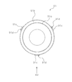
- FIG. 15 is a top view of the inspection chute 91.
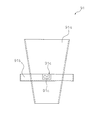
- FIG. 16 is a side view of the inspection chute 91 as viewed from the arrow XVI in FIG.
- the inspection chute 91 mainly includes a cylindrical portion 91a and an attachment portion 91b.
- the cylindrical part 91a is a member through which the article to be packaged C discharged from the combination weighing unit 2 passes.
- the cylindrical portion 91a has a tapered shape whose diameter gradually decreases from the upper side to the lower side.
- the attachment portion 91b is attached to the outer peripheral surface of the tubular portion 91a at the middle portion in the vertical direction of the tubular portion 91a.
- the attachment portion 91b has a shape like a circular tray.
- a plurality of hook portions 91c are attached to the outer peripheral surface of the attachment portion 91b.
- the plurality of hook portions 91c are attached at equal intervals along the circumferential direction of the attachment portion 91b.
- the attachment portion 91 b has three hook portions 91 c.
- the hook portion 91c protrudes further radially outward from the outer peripheral surface of the attachment portion 91b.
- the hook 91c has a hook-shaped hook groove 91d.
- the attachment portion 91b is a member for hooking and attaching the inspection chute 91 to the metal detector 92.
- the metal detector 92 has a protrusion for hooking on the hook groove 91d on the inner peripheral surface of the hole through which the inspection chute 91 passes. The operator can easily attach the inspection chute 91 to the metal detector 92 by slightly moving the inspection chute 91 in the vertical direction and the circumferential direction, and can easily remove the inspection chute 91 from the metal detector 92. it can.
- the inspection unit support device 80 is attached to the weighing packaging system 100.
- the inspection unit support device 80 may be used for other purposes.
- the inspection unit support device 80 can be used to support devices that need to be regularly accessed for maintenance work or the like.
- the inspection unit 9 includes an inspection chute 91 and a metal detector 92.
- the metal detector 92 is a device that detects metallic foreign matter mixed in the packaged article C that passes through the inspection chute 91.
- the inspection unit 9 may include a device other than the metal detector 92 instead of the metal detector 92, and further includes a device other than the metal detector 92 in addition to the metal detector 92. May be.
- the inspection unit 9 may further include an X-ray inspection machine as a device that detects foreign matter mixed in the article to be packaged C.
- Inspection Unit 80 Inspection Unit Support Device 81 Fixed Frame (First Member) 82 Guide frame (second member) 82a A pair of horizontal rails (a pair of horizontal sections) 82b A pair of horizontal rails (a pair of horizontal sections) 82c Inclined rail (inclined part) 91 Inspection chute (cylinder member) 92 Metal detector (inspector) C Package (article)
Landscapes
- Engineering & Computer Science (AREA)
- Mechanical Engineering (AREA)
- Physics & Mathematics (AREA)
- Life Sciences & Earth Sciences (AREA)
- Remote Sensing (AREA)
- General Physics & Mathematics (AREA)
- Electromagnetism (AREA)
- Environmental & Geological Engineering (AREA)
- Geology (AREA)
- General Life Sciences & Earth Sciences (AREA)
- Geophysics (AREA)
- Containers And Plastic Fillers For Packaging (AREA)
- Geophysics And Detection Of Objects (AREA)
Abstract
Priority Applications (3)
| Application Number | Priority Date | Filing Date | Title |
|---|---|---|---|
| AU2017232328A AU2017232328A1 (en) | 2016-03-16 | 2017-03-09 | Inspection unit support apparatus and inspection apparatus |
| EP17766542.9A EP3432038A4 (fr) | 2016-03-16 | 2017-03-09 | Dispositif de support d'unité d'inspection et appareil d'inspection |
| CN201780017071.4A CN108780160A (zh) | 2016-03-16 | 2017-03-09 | 检查单元支撑装置及检查装置 |
Applications Claiming Priority (2)
| Application Number | Priority Date | Filing Date | Title |
|---|---|---|---|
| JP2016052482A JP2017166976A (ja) | 2016-03-16 | 2016-03-16 | 検査ユニット支持装置、および、検査装置 |
| JP2016-052482 | 2016-03-16 |
Publications (1)
| Publication Number | Publication Date |
|---|---|
| WO2017159541A1 true WO2017159541A1 (fr) | 2017-09-21 |
Family
ID=59852087
Family Applications (1)
| Application Number | Title | Priority Date | Filing Date |
|---|---|---|---|
| PCT/JP2017/009517 Ceased WO2017159541A1 (fr) | 2016-03-16 | 2017-03-09 | Dispositif de support d'unité d'inspection et appareil d'inspection |
Country Status (5)
| Country | Link |
|---|---|
| EP (1) | EP3432038A4 (fr) |
| JP (1) | JP2017166976A (fr) |
| CN (1) | CN108780160A (fr) |
| AU (1) | AU2017232328A1 (fr) |
| WO (1) | WO2017159541A1 (fr) |
Cited By (1)
| Publication number | Priority date | Publication date | Assignee | Title |
|---|---|---|---|---|
| DE102024131245A1 (de) * | 2024-10-25 | 2026-04-30 | Syntegon Technology Gmbh | Dosiervorrichtung für eine Verpackungsmaschine, Verpackungsmaschine mit einer derartigen Dosiervorrichtung sowie Verfahren zu einem Betrieb einer Dosiervorrichtung |
Families Citing this family (3)
| Publication number | Priority date | Publication date | Assignee | Title |
|---|---|---|---|---|
| JP6804764B2 (ja) | 2017-03-17 | 2020-12-23 | 株式会社イシダ | 組合せ計量装置 |
| FR3093093B1 (fr) * | 2019-02-25 | 2021-03-05 | Acemma | Dispositif de dosage motorise a bande, systeme d’ensachage associe |
| JP7072953B1 (ja) * | 2021-11-11 | 2022-05-23 | 吉泉産業株式会社 | 計量異物検知包装装置 |
Citations (7)
| Publication number | Priority date | Publication date | Assignee | Title |
|---|---|---|---|---|
| JPS63148130A (ja) | 1986-12-10 | 1988-06-21 | Yamato Scale Co Ltd | 金属検出器付き計量包装装置 |
| JPH0127061Y2 (fr) * | 1981-09-22 | 1989-08-14 | ||
| JP2000206342A (ja) * | 1999-01-13 | 2000-07-28 | Hitachi Cable Ltd | 光接続部収納トレイの引出し構造 |
| JP2002156462A (ja) * | 2000-11-21 | 2002-05-31 | Ishida Co Ltd | 金属検出装置 |
| WO2007073900A2 (fr) * | 2005-12-23 | 2007-07-05 | Marani S.R.L. | Procede d'assaisonnement reposant sur l'utilisation d'un assaisonnement en poudre et appareil permettant la mise en oeuvre dudit procede |
| JP2011138910A (ja) * | 2009-12-28 | 2011-07-14 | Hitachi Kokusai Electric Inc | 機器収納用ラック |
| JP2014511484A (ja) | 2011-02-25 | 2014-05-15 | ティエヌエイ オーストラリア ピーティワイ リミテッド | 金属検出器 |
Family Cites Families (6)
| Publication number | Priority date | Publication date | Assignee | Title |
|---|---|---|---|---|
| JPH09315165A (ja) * | 1996-05-29 | 1997-12-09 | Toyota Autom Loom Works Ltd | ガスボンベ搭載装置 |
| JP2002296099A (ja) * | 2001-03-30 | 2002-10-09 | Anritsu Corp | 組合せ計量装置 |
| AU2003903509A0 (en) * | 2003-07-08 | 2003-07-24 | Tna Australia Pty Limited | A packaging machine former support |
| JP2008161581A (ja) * | 2006-12-28 | 2008-07-17 | Oaks Kk | 履物収納棚 |
| JP5030728B2 (ja) * | 2007-10-04 | 2012-09-19 | 大和製衡株式会社 | 組合せ秤の集合ホッパ着脱装置 |
| JP2013230842A (ja) * | 2012-04-27 | 2013-11-14 | Ishida Co Ltd | 製袋包装機 |
-
2016
- 2016-03-16 JP JP2016052482A patent/JP2017166976A/ja active Pending
-
2017
- 2017-03-09 AU AU2017232328A patent/AU2017232328A1/en not_active Abandoned
- 2017-03-09 EP EP17766542.9A patent/EP3432038A4/fr not_active Withdrawn
- 2017-03-09 WO PCT/JP2017/009517 patent/WO2017159541A1/fr not_active Ceased
- 2017-03-09 CN CN201780017071.4A patent/CN108780160A/zh active Pending
Patent Citations (7)
| Publication number | Priority date | Publication date | Assignee | Title |
|---|---|---|---|---|
| JPH0127061Y2 (fr) * | 1981-09-22 | 1989-08-14 | ||
| JPS63148130A (ja) | 1986-12-10 | 1988-06-21 | Yamato Scale Co Ltd | 金属検出器付き計量包装装置 |
| JP2000206342A (ja) * | 1999-01-13 | 2000-07-28 | Hitachi Cable Ltd | 光接続部収納トレイの引出し構造 |
| JP2002156462A (ja) * | 2000-11-21 | 2002-05-31 | Ishida Co Ltd | 金属検出装置 |
| WO2007073900A2 (fr) * | 2005-12-23 | 2007-07-05 | Marani S.R.L. | Procede d'assaisonnement reposant sur l'utilisation d'un assaisonnement en poudre et appareil permettant la mise en oeuvre dudit procede |
| JP2011138910A (ja) * | 2009-12-28 | 2011-07-14 | Hitachi Kokusai Electric Inc | 機器収納用ラック |
| JP2014511484A (ja) | 2011-02-25 | 2014-05-15 | ティエヌエイ オーストラリア ピーティワイ リミテッド | 金属検出器 |
Non-Patent Citations (1)
| Title |
|---|
| See also references of EP3432038A4 * |
Cited By (1)
| Publication number | Priority date | Publication date | Assignee | Title |
|---|---|---|---|---|
| DE102024131245A1 (de) * | 2024-10-25 | 2026-04-30 | Syntegon Technology Gmbh | Dosiervorrichtung für eine Verpackungsmaschine, Verpackungsmaschine mit einer derartigen Dosiervorrichtung sowie Verfahren zu einem Betrieb einer Dosiervorrichtung |
Also Published As
| Publication number | Publication date |
|---|---|
| JP2017166976A (ja) | 2017-09-21 |
| EP3432038A1 (fr) | 2019-01-23 |
| CN108780160A (zh) | 2018-11-09 |
| EP3432038A4 (fr) | 2019-01-23 |
| AU2017232328A1 (en) | 2018-11-08 |
Similar Documents
| Publication | Publication Date | Title |
|---|---|---|
| JP4169836B2 (ja) | 計量包装システム | |
| CN109689511B (zh) | 计量包装装置 | |
| JP2017166976A (ja) | 検査ユニット支持装置、および、検査装置 | |
| JP2001002013A (ja) | 計量及び製袋包装システム | |
| CN108290651B (zh) | 制袋包装机 | |
| JP2005335715A (ja) | 不良品検出装置およびこれを備えた製袋包装システム | |
| EP3428587B1 (fr) | Dispositif de pesage combiné | |
| JP2010230621A (ja) | 組合せ秤及びそれを備える計量包装システム | |
| JP6673685B2 (ja) | 計量包装システム | |
| WO2018169047A1 (fr) | Dispositif de pesage combiné | |
| JP2017132499A (ja) | 縦型包装機械の噛み込み判定装置 | |
| JP2000289717A (ja) | 計量包装検査システム | |
| CN112918810A (zh) | 改善判断系统 | |
| JP2021001010A (ja) | 縦型製袋包装機 | |
| JP7359749B2 (ja) | 搬送装置、物品検査装置および振分け装置 | |
| JP5188102B2 (ja) | 箱詰め装置 | |
| JP6073841B2 (ja) | 横形製袋充填機における物品判別装置 | |
| JP4027506B2 (ja) | 商品処理システム | |
| CN115703548A (zh) | 计量包装系统 | |
| JP2021001011A (ja) | 縦型製袋包装機 | |
| JP6883834B2 (ja) | タイミング調整可能な包装機 | |
| JP2008094445A (ja) | 商品処理システムにおける設定入力装置 | |
| JP6223928B2 (ja) | 横形製袋充填機における物品判別装置 | |
| JP6522472B2 (ja) | 計量装置 | |
| JP6556472B2 (ja) | 多段階選別システム |
Legal Events
| Date | Code | Title | Description |
|---|---|---|---|
| NENP | Non-entry into the national phase |
Ref country code: DE |
|
| WWE | Wipo information: entry into national phase |
Ref document number: 2017766542 Country of ref document: EP |
|
| ENP | Entry into the national phase |
Ref document number: 2017766542 Country of ref document: EP Effective date: 20181016 |
|
| ENP | Entry into the national phase |
Ref document number: 2017232328 Country of ref document: AU Date of ref document: 20170309 Kind code of ref document: A |
|
| 121 | Ep: the epo has been informed by wipo that ep was designated in this application |
Ref document number: 17766542 Country of ref document: EP Kind code of ref document: A1 |