WO2017159546A1 - Procédé de soudage par joints et dispositif de soudage par joints - Google Patents
Procédé de soudage par joints et dispositif de soudage par joints Download PDFInfo
- Publication number
- WO2017159546A1 WO2017159546A1 PCT/JP2017/009584 JP2017009584W WO2017159546A1 WO 2017159546 A1 WO2017159546 A1 WO 2017159546A1 JP 2017009584 W JP2017009584 W JP 2017009584W WO 2017159546 A1 WO2017159546 A1 WO 2017159546A1
- Authority
- WO
- WIPO (PCT)
- Prior art keywords
- seam welding
- laminate
- welding
- roller electrode
- seam
- Prior art date
- Legal status (The legal status is an assumption and is not a legal conclusion. Google has not performed a legal analysis and makes no representation as to the accuracy of the status listed.)
- Ceased
Links
Images

Classifications
-
- B—PERFORMING OPERATIONS; TRANSPORTING
- B23—MACHINE TOOLS; METAL-WORKING NOT OTHERWISE PROVIDED FOR
- B23K—SOLDERING OR UNSOLDERING; WELDING; CLADDING OR PLATING BY SOLDERING OR WELDING; CUTTING BY APPLYING HEAT LOCALLY, e.g. FLAME CUTTING; WORKING BY LASER BEAM
- B23K11/00—Resistance welding; Severing by resistance heating
- B23K11/06—Resistance welding; Severing by resistance heating using roller electrodes
- B23K11/061—Resistance welding; Severing by resistance heating using roller electrodes for welding rectilinear seams
- B23K11/062—Resistance welding; Severing by resistance heating using roller electrodes for welding rectilinear seams for welding longitudinal seams of tubes
-
- B—PERFORMING OPERATIONS; TRANSPORTING
- B23—MACHINE TOOLS; METAL-WORKING NOT OTHERWISE PROVIDED FOR
- B23K—SOLDERING OR UNSOLDERING; WELDING; CLADDING OR PLATING BY SOLDERING OR WELDING; CUTTING BY APPLYING HEAT LOCALLY, e.g. FLAME CUTTING; WORKING BY LASER BEAM
- B23K11/00—Resistance welding; Severing by resistance heating
- B23K11/06—Resistance welding; Severing by resistance heating using roller electrodes
-
- B—PERFORMING OPERATIONS; TRANSPORTING
- B23—MACHINE TOOLS; METAL-WORKING NOT OTHERWISE PROVIDED FOR
- B23K—SOLDERING OR UNSOLDERING; WELDING; CLADDING OR PLATING BY SOLDERING OR WELDING; CUTTING BY APPLYING HEAT LOCALLY, e.g. FLAME CUTTING; WORKING BY LASER BEAM
- B23K11/00—Resistance welding; Severing by resistance heating
- B23K11/10—Spot welding; Stitch welding
- B23K11/11—Spot welding
- B23K11/115—Spot welding by means of two electrodes placed opposite one another on both sides of the welded parts
-
- B—PERFORMING OPERATIONS; TRANSPORTING
- B23—MACHINE TOOLS; METAL-WORKING NOT OTHERWISE PROVIDED FOR
- B23K—SOLDERING OR UNSOLDERING; WELDING; CLADDING OR PLATING BY SOLDERING OR WELDING; CUTTING BY APPLYING HEAT LOCALLY, e.g. FLAME CUTTING; WORKING BY LASER BEAM
- B23K11/00—Resistance welding; Severing by resistance heating
- B23K11/24—Electric supply or control circuits therefor
- B23K11/25—Monitoring devices
- B23K11/252—Monitoring devices using digital means
- B23K11/253—Monitoring devices using digital means the measured parameter being a displacement or a position
-
- B—PERFORMING OPERATIONS; TRANSPORTING
- B23—MACHINE TOOLS; METAL-WORKING NOT OTHERWISE PROVIDED FOR
- B23K—SOLDERING OR UNSOLDERING; WELDING; CLADDING OR PLATING BY SOLDERING OR WELDING; CUTTING BY APPLYING HEAT LOCALLY, e.g. FLAME CUTTING; WORKING BY LASER BEAM
- B23K11/00—Resistance welding; Severing by resistance heating
- B23K11/30—Features relating to electrodes
- B23K11/31—Electrode holders and actuating devices therefor
- B23K11/318—Supporting devices for electrode holders
-
- B—PERFORMING OPERATIONS; TRANSPORTING
- B23—MACHINE TOOLS; METAL-WORKING NOT OTHERWISE PROVIDED FOR
- B23K—SOLDERING OR UNSOLDERING; WELDING; CLADDING OR PLATING BY SOLDERING OR WELDING; CUTTING BY APPLYING HEAT LOCALLY, e.g. FLAME CUTTING; WORKING BY LASER BEAM
- B23K2101/00—Articles made by soldering, welding or cutting
- B23K2101/006—Vehicles
-
- B—PERFORMING OPERATIONS; TRANSPORTING
- B23—MACHINE TOOLS; METAL-WORKING NOT OTHERWISE PROVIDED FOR
- B23K—SOLDERING OR UNSOLDERING; WELDING; CLADDING OR PLATING BY SOLDERING OR WELDING; CUTTING BY APPLYING HEAT LOCALLY, e.g. FLAME CUTTING; WORKING BY LASER BEAM
- B23K2101/00—Articles made by soldering, welding or cutting
- B23K2101/18—Sheet panels
Definitions
- the present invention relates to a seam welding method for performing seam welding of a laminate by energizing between the roller electrode pair while moving the laminate sandwiched between the roller electrode pair relative to the roller electrode pair, and
- the present invention relates to a seam welding apparatus.
- Seam welding is widely known as a technique for joining metal plates continuously in a linear fashion.
- the energized state between the roller electrode pair while relatively moving the laminated body and the roller electrode pair There is a method in which welding is performed by successively repeating the on / off operation (for example, Patent Document 1).
- Such seam welding is automatically performed by a seam welding apparatus, and therefore, it is useful because the joining work can be performed with high accuracy in a short time as compared with the case where the seam welding is performed manually.
- the present invention has been made in view of the above-described conventional problems, and even when a failure occurs in equipment such as a power outage and seam welding stops urgently, spot welding is performed in a separate process after the seam welding is completed. It is an object of the present invention to provide a seam welding method and a seam welding apparatus capable of performing seam welding without an unwelded portion.
- a laminated body formed by laminating a plurality of workpieces is sandwiched between roller electrode pairs, and the roller electrode pair is moved while moving the roller electrode pair relative to the laminated body.
- seam welding method of the present invention when seam welding is performed, a failure occurs in the facility such as a power failure, and the seam welding is stopped in an emergency state with the power supply to the roller electrode pair cut off.
- the electrode pair is moved by a predetermined distance in the direction opposite to the relative traveling direction of the roller electrode pair with respect to the laminated plate during seam welding, spot welding is executed at that position, and then seam welding is resumed. Therefore, even when seam welding stops urgently and an unwelded portion is generated, the bead continuity can be maintained by performing spot welding on the unwelded portion after returning by a predetermined distance. Therefore, it is not necessary to provide a separate spot welding process after seam welding.
- the position where spot welding is performed on the laminated body is a position separated from the end portion of the nugget formed by seam welding formed on the laminated body immediately before an emergency stop.
- the position at which spot welding is performed on the laminate is on a path along which the laminate moves relative to the roller electrode pair. This is because spot welding is performed on the seam welding path, so that the position can be easily set.
- the spot welding is performed such that a nugget formed by seam welding formed on the laminate immediately before an emergency stop overlaps with a nugget formed on the laminate by the spot welding. It is preferable. By doing in this way, since the terminal part of the nugget by seam welding and the nugget of spot welding are connected, a continuous nugget can be formed and sealability can be improved.
- the nugget formed on the laminate by the spot welding overlaps with the nugget formed on the laminate by the seam welding. It is preferable to carry out. By doing in this way, since the nugget of spot welding and the starting end part of the nugget by seam welding are connected, a continuous nugget can be formed and the sealing performance can be improved.
- the welding position by seam welding of the laminate is stored in the storage means as needed, and the roller electrode pair is set when the seam welding is stopped. It is preferable that the predetermined distance that moves in the direction opposite to the relative movement direction at the time is determined based on the welding position stored in the storage means when stopped. As described above, the predetermined distance is determined based on the welding position information stored in the storage means, and the spot welding position can be accurately set by setting the predetermined distance.
- the relative moving speed of the roller electrode pair with respect to the laminated body is stored in a storage means as needed, and is set when the seam welding is stopped.
- the predetermined distance by which the body moves in the direction opposite to the relative movement direction during seam welding is obtained based on the movement speed stored at the time of stop in the storage means, and the distance by which the laminate is relatively moved immediately after the stop is determined. It is preferable to determine based on the distance. If the movement speed when seam welding is stopped is known, the distance until the relative movement of the roller electrode pair with respect to the laminate stops can be calculated.
- the said moving speed can be memorize
- the seam welding apparatus of the present invention is characterized by performing seam welding of the laminate using the above seam welding method.
- the seam welding device of the present invention enables spot welding to be performed on unwelded parts even when equipment failure such as a power failure occurs and seam welding stops, and spot welding in a separate process is performed after seam welding is completed. There is no need to do.
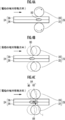
- FIG. 4A is a schematic explanatory diagram at a first point in time of an energized state and a welded state of the laminate.
- FIG. 4B is a schematic explanatory diagram at a second time point of the energized state and the welded state of the laminated body.
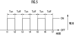
- FIG. 4C is a schematic explanatory diagram at a third time point of the energized state and the welded state of the laminated body. 2 is a timing chart of on / off operation of the switch shown in FIG. 1.
- FIG. 4A is a schematic explanatory diagram at a first point in time of an energized state and a welded state of the laminate.
- FIG. 4B is a schematic explanatory diagram at a second time point of the energized state and the welded state of the laminated body.
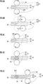
- FIG. 6A is a schematic diagram illustrating a first operation of the roller electrode pair from when the seam welding is stopped to when the seam welding is resumed.
- FIG. 6B is a schematic diagram illustrating a second operation of the roller electrode pair from when the seam welding is stopped to when the seam welding is resumed.
- FIG. 6C is a schematic diagram illustrating a third operation of the roller electrode pair from when the seam welding is stopped to when the seam welding is resumed.
- FIG. 6D is a schematic diagram illustrating a fourth operation of the roller electrode pair from when the seam welding is stopped to when the seam welding is resumed.
- FIG. 6E is a schematic diagram illustrating a fifth operation of the roller electrode pair from when the seam welding is stopped to when the seam welding is resumed.
- FIG. 6A is a schematic diagram illustrating a first operation of the roller electrode pair from when the seam welding is stopped to when the seam welding is resumed.
- FIG. 6B is a schematic diagram illustrating a second operation of the roller electrode pair from when the seam welding is
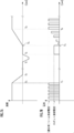
- FIG. 7A is a schematic explanatory diagram showing a change in moving speed of the roller electrode pair with respect to elapsed time in time series.
- FIG. 7B is a schematic explanatory diagram showing changes in energization state of the roller electrode pair 23 with respect to elapsed time in time series.
- FIG. 1 is a side view showing an outline of a seam welding apparatus 10 according to the present embodiment.
- the seam welding apparatus 10 includes an articulated robot 12 and a seam welder 16 supported by a tip arm 14 of the articulated robot 12.
- the seam welding apparatus 10 configured by combining the articulated robot 12 and the seam welder 16 in this way is known as described in, for example, Japanese Patent Application Laid-Open No. 2007-167896 and Utility Model Registration No. 3124033. It is. Therefore, the detailed description about the said structure is abbreviate
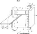
- the seam welder 16 includes a first roller electrode 20 and a second roller electrode 22 supported on the tip arm 14 via a mount 18 (see FIG. 1).
- the first roller electrode 20 and the second roller electrode 22 may be collectively referred to as a roller electrode pair 23.
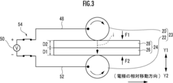
- the first roller electrode 20 is disposed above the stacked body 24, and the second roller electrode 22 is disposed below the stacked body 24. That is, the seam welder 16 sandwiches the laminate 24 with the roller electrode pair 23.
- the laminate 24 to be welded is configured by laminating two metal plates 26 and 28 in this order from below.
- the metal plates 26 and 28 are not particularly limited, and are made of, for example, JAC590, JAC780, or JAC980 (all of which are high-performance high-tensile steel plates defined in the Japan Iron and Steel Federation standard, so-called high-tensile materials).
- the thicknesses of the metal plates 26 and 28 are set to D1 and D2 (for example, about 1 mm to about 2 mm), respectively.
- the number of metal plates to be laminated is not limited to two shown in this example, and may be three or more.
- the guide 18 is laid on the mount 18.
- the guide rail 30 includes a first cylinder (not shown) for moving the first roller electrode 20 supported by the first moving table 32 in a direction toward or away from the second roller electrode 22, and a second movement.
- a second cylinder (not shown) for displacing the second roller electrode 22 supported by the table 34 in a direction approaching or separating from the first roller electrode 20 is supported.
- the first moving table 32 supports a first rotation motor (not shown) for energizing the first roller electrode 20, and the second moving table 34 rotates the second roller electrode 22.
- a second rotating motor (not shown) for energizing is supported. Since such a configuration is known, illustration and detailed description are omitted.
- a servo motor or the like may be employed instead of the first cylinder and the second cylinder.
- a concave portion 38 of the first moving table 32 that supports the first roller electrode 20 and a concave portion 40 of the second moving table 34 that supports the second roller electrode 22 are slidable on the convex portion 36 of the guide rail 30. Engaged.
- the first moving table 32 is connected to a first rod (not shown) of the first cylinder
- the second moving table 34 is connected to a second rod (not shown) of the second cylinder.
- first roller electrode 20 is displaced in a direction (arrow Y2, Y1 direction) approaching or separating from the second roller electrode 22 as the first rod of the first cylinder moves back and forth.
- second roller electrode 22 is displaced in a direction (arrow Y1, Y2 direction) approaching or separating from the first roller electrode 20 as the second rod of the second cylinder moves back and forth.
- a first shaft 42 is interposed between the first roller electrode 20 and the first moving table 32. As the first shaft 42 rotates under the action of the first rotation motor, the first roller electrode 20 rotates. Similarly, the second roller electrode 22 rotates as the second shaft 44 rotates under the action of the second rotation motor. The first roller electrode 20 and the second roller electrode 22 can be rotated not only in the normal direction but also in the reverse direction.
- a speed sensor 46 capable of detecting an actual moving speed of the first roller electrode 20 (hereinafter also referred to as an actual speed va) is embedded in the first shaft 42.
- the sensor system and / or arrangement position of the speed sensor 46 may be arbitrarily changed within a range in which the relative actual speed va between the roller electrode pair 23 and the laminate 24 can be accurately measured.
- the first roller electrode 20 is electrically connected to the positive electrode (so-called hot side, also referred to as a positive electrode for convenience) of the AC power supply 50 via a first lead wire (power line) 48. Is done.
- the second roller electrode 22 is electrically connected to the negative electrode (so-called cold side, also referred to as a minus electrode for convenience) of the AC power supply 50 via a second lead wire (power line) 52.
- two-pole switches 54 are interposed between the first lead wires 48 and the second lead wires 52, respectively.
- an electronic switch using a power element can be adopted as the switch 54.
- the ON / OFF operation of the switch 54 is sequentially repeated at a relatively short time interval.
- an encode on state a state in which a current is temporarily supplied between the roller electrode pair 23 in the process of performing seam welding
- a state in which the current supply between the roller electrode pair 23 is temporarily stopped is referred to as an “energization off state”.
- the first and second cylinders, the first and second rotating motors, the speed sensor 46, the AC power supply 50, and the switch 54 are electrically connected to the control unit 56 (see FIG. 1) as control means. Are connected to each other.
- the control unit 56 includes a drive control unit 58 that drives and controls the first and second cylinders based on previously acquired teaching data, an energization control unit 60 that controls the energization state between the roller electrode pair 23, and an energization control unit 60.
- the drive control unit 58 includes a memory (storage means) that stores a welding position in the laminate 24 during seam welding and / or a relative moving speed of the laminate 24 with respect to the roller electrode pair 23 as needed.
- the seam welding apparatus 10 basically includes the seam welding machine 16 configured as described above. Next, the function and effect will be described in relation to the seam welding method according to this embodiment.
- the articulated robot 12 moves the tip arm 14, that is, the seam welder 16 so that the laminate 24 is disposed between the first roller electrode 20 and the second roller electrode 22.
- the first cylinder and the second cylinder are urged under the action of the control unit 56 (drive control unit 58), and accordingly, the first rod and the second rod start moving forward. That is, the second roller electrode 22 is displaced in the direction of the arrow Y1 so as to approach the first roller electrode 20, and the arrow Y2 so that the first roller electrode 20 approaches the second roller electrode 22. Displaces in the direction. As a result, the laminate 24 is sandwiched between the first roller electrode 20 and the second roller electrode 22.
- the drive control unit 58 determines that the pressure (F1) of the first roller electrode 20 against the metal plate 28 is balanced with the pressure (F2) of the second roller electrode 22 against the metal plate 26.
- the driving force of the first rod and the second rod of the cylinder and the second cylinder and the driving force of the second rod of the second cylinder are controlled.
- the drive control unit 58 moves the roller electrode pair 23 in the moving direction at a predetermined speed by rotating the first and second rotation motors at a predetermined rotation speed. Then, the energization control unit 60 turns on the switch 54 and starts energization from the AC power supply 50 to the stacked body 24.
- first roller electrode 20 is connected to the positive electrode of the AC power source 50 and the second roller electrode 22 is connected to the negative electrode of the AC power source 50, as shown in FIG.
- Current i flows from the first to the second roller electrode 22.
- FIG. 4A to 4C are schematic explanatory diagrams showing the energized state and the welded state of the laminate 24 in time series.
- FIG. 5 is a timing chart of the on / off operation of the switch 54 shown in FIG.
- the switch 54 since the switch 54 is in the ON state from time t1 to time t2, the current i flows from the AC power supply 50 to the second roller electrode 22 through the first roller electrode 20. Then, resistance heat is generated in the vicinity of the contact surface between the metal plate 26 and the metal plate 28, and heating / melting is started by Joule heat based on the current i. Thereby, a nugget 80 is formed at a position between the first roller electrode 20 and the second roller electrode 22.
- the energization control unit 60 turns off the switch 54 (off state) and stops energization from the AC power supply 50 to the stacked body 24.
- a new position is formed between the first roller electrode 20 and the second roller electrode 22 as described above.
- a nugget 82 is formed.
- the roller electrode pair 23 is moved along the movement direction, the nugget 82 is formed at a position on the right side (movement direction side) of the position of the nugget 80.
- a continuous nugget 84 in which the nuggets 80 and 82 are connected is formed.
- the nuggets 80 and 82 which adjoin each other via the duplication part 86 are mutually connected, and the continuity of a nugget is maintained.
- the off state (time t4 to t5), the on state (time t5 to t6), and the off state (time t6 to t7) are repeated according to the on / off operation of the switch 54.
- seam welding is performed as described above.
- FIG. 6 and FIG. 7 for the processing when a failure occurs in a facility such as a power failure and seam welding is stopped in a state where the power supply to the roller electrode pair is cut off and then recovered from the stop. explain.
- FIGS. 6A to 6E are diagrams schematically showing the operation and welding state of the roller electrode pair 23 and the laminate 24 from the time when seam welding is stopped to the time when seam welding is resumed.
- FIG. 7B shows a change in the energization state of the roller electrode pair 23 with respect to the elapsed time.
- FIG. 6A shows a state at the time when seam welding is stopped (time T 1 in FIG. 7). At this time, energization to the roller electrode pair 23 is stopped, but the movement of the roller electrode pair 23 is suddenly stopped. Stop after moving a certain distance due to inertia.
- FIG. 6B shows a state where the roller electrode pair 23 is completely stopped (time T 2 in FIG. 7), and the position of the roller electrode pair 23 corresponding to FIG. 6A is indicated by a broken line. From FIG. 6B, the roller electrode pair 23 has been moved and stopped by the distance d from the time when the seam welding is stopped.
- the nugget 80 formed by the roller electrode pair 23 is not formed after the energization of the roller electrode pair 23 is stopped, and therefore reaches the end 80E. At the distance d, since the energization to the roller electrode pair 23 is stopped, no nugget is formed.
- the roller electrode pair 23 is rotated in the opposite direction to that during the seam welding, and is moved and stopped in the opposite direction by a predetermined distance (time points T 3 to T 4 in FIG. 7).
- the predetermined distance is separated from the end portion of the nugget formed by seam welding formed in the laminate 24 immediately before the seam welding is stopped in order to suppress the current splitting of spot welding and to improve the nugget formed by spot welding. It is preferable that the position is the same. In other words, the distance is preferably less than the distance d.
- the predetermined distance by which the roller electrode pair 23 is moved in the reverse direction is a welding position in the laminate 24 during seam welding, which is stored in the memory of the drive control unit 58, and is stored when seam welding is stopped. It can be determined based on the welding position. That is, when seam welding is resumed after seam welding is stopped, the distance (distance d in FIG. 6B) from the welding position at the time of stopping stored in the memory to the position (current position) in the stopped state can be obtained.
- the predetermined distance may be set to be less than the obtained distance d.
- the distance d can be obtained based on the relative moving speed of the laminated body 24 with respect to the roller electrode pair 23 during seam welding stored in the memory of the drive control unit 58. Since the distance d is substantially proportional to the relative moving speed of the laminated body 24 with respect to the roller electrode pair 23 immediately before the seam welding is stopped, the distance d can be obtained based on the moving speed.
- the predetermined distance may be set to be less than the obtained distance d.
- the position where spot welding is performed is preferably on a path along which the laminate 24 moves relative to the roller electrode pair 23 in order to easily set the position.
- the state of sandwiching the laminated body 24 of the roller electrode pair 23 may be released, and the roller electrodes 20 and 21 may be moved away from the laminated body 24 in the opposite direction.
- spot welding is performed (time points T 4 to T 5 in FIG. 7). This spot welding is performed at a lower current and direct current than seam welding. And the nugget 86 is formed by the said spot welding as shown in FIG.
- spot welding is performed so that a nugget formed by seam welding formed on the laminate 24 immediately before the seam welding is stopped overlaps with a nugget 86 formed on the laminate 24 by spot welding. It is preferable to do. By doing in this way, since the terminal part of the nugget by seam welding and the nugget of spot welding are connected, a continuous nugget can be formed and sealability can be improved.
- seam welding is resumed, and seam welding is performed without any unwelded portions as shown in FIG. 6E.
- the seam welding is performed such that the nugget 86 formed on the laminated body 24 by spot welding and the nugget 80 formed on the laminated body 24 by resuming seam welding overlap each other. It is preferable to do. Since the nugget 86 by spot welding and the start end portion 80B of the nugget 80 by seam welding are connected, a continuous nugget can be formed and the sealing performance can be improved.
- the energization of the roller electrode pair 23 is preferably performed by gradually increasing the current until the moving speed of the laminate 24 with respect to the roller electrode pair 23 reaches a constant speed (time points T 5 to T 6 in FIG. 7). This is because if a current is suddenly applied in a state where the moving speed is low, heat is generated more locally than necessary, and defects such as perforations may occur.
- the current is not gradually increased with respect to the roller electrode pair 23, but immediately before the moving speed of the laminate 24 with respect to the roller electrode pair 23 becomes a constant speed (FIG. 7).
- current may be supplied so that the current value in the case of performing normal seam welding is reached instantaneously. This is because if the moving speed is equal to or higher than a certain speed, local heat generation is mitigated and problems such as perforation are not generated.
- the present invention is not limited to the above-described embodiment, and can of course be freely changed without departing from the gist of the present invention.
- the present embodiment only the roller electrode pair 23 is moved, but at least one of the roller electrode pair 23 and the laminate 24 may be moved. This is because the present invention can be applied as long as both are relatively moved.
- spot welding is performed by stopping the rotation of the roller electrode pair 23. However, if it is extremely small, it may not be completely stopped. Further, in spot welding, a constant current is applied for a long time, but the voltage may be changed or a pulse waveform may be used as long as it is somewhat.
Landscapes
- Engineering & Computer Science (AREA)
- Mechanical Engineering (AREA)
- Resistance Welding (AREA)
Abstract
Priority Applications (4)
| Application Number | Priority Date | Filing Date | Title |
|---|---|---|---|
| US16/084,716 US20190070690A1 (en) | 2016-03-14 | 2017-03-09 | Seam welding method and seam welding device |
| CN201780017291.7A CN108778599B (zh) | 2016-03-14 | 2017-03-09 | 缝焊方法及缝焊装置 |
| JP2018505884A JP6542979B2 (ja) | 2016-03-14 | 2017-03-09 | シーム溶接方法及びシーム溶接装置 |
| CA3017303A CA3017303C (fr) | 2016-03-14 | 2017-03-09 | Procede de soudage par joints et dispositif de soudage par joints |
Applications Claiming Priority (2)
| Application Number | Priority Date | Filing Date | Title |
|---|---|---|---|
| JP2016-049649 | 2016-03-14 | ||
| JP2016049649 | 2016-03-14 |
Publications (1)
| Publication Number | Publication Date |
|---|---|
| WO2017159546A1 true WO2017159546A1 (fr) | 2017-09-21 |
Family
ID=59850317
Family Applications (1)
| Application Number | Title | Priority Date | Filing Date |
|---|---|---|---|
| PCT/JP2017/009584 Ceased WO2017159546A1 (fr) | 2016-03-14 | 2017-03-09 | Procédé de soudage par joints et dispositif de soudage par joints |
Country Status (5)
| Country | Link |
|---|---|
| US (1) | US20190070690A1 (fr) |
| JP (1) | JP6542979B2 (fr) |
| CN (1) | CN108778599B (fr) |
| CA (1) | CA3017303C (fr) |
| WO (1) | WO2017159546A1 (fr) |
Families Citing this family (2)
| Publication number | Priority date | Publication date | Assignee | Title |
|---|---|---|---|---|
| JP6767523B2 (ja) * | 2019-01-09 | 2020-10-14 | 本田技研工業株式会社 | 電極姿勢確認装置及び電極姿勢確認方法 |
| CN110587095B (zh) * | 2019-08-16 | 2022-05-10 | 广州微点焊设备有限公司 | 显微电阻焊点焊机 |
Citations (6)
| Publication number | Priority date | Publication date | Assignee | Title |
|---|---|---|---|---|
| JPH1158026A (ja) * | 1997-08-21 | 1999-03-02 | Toyota Motor Corp | シーム溶接方法 |
| JPH1177326A (ja) * | 1997-08-28 | 1999-03-23 | Dengensha Mfg Co Ltd | 抵抗シーム溶接方法とその溶接機 |
| JP2000343229A (ja) * | 1999-06-04 | 2000-12-12 | Toyota Auto Body Co Ltd | シーム溶接装置 |
| WO2014007145A1 (fr) * | 2012-07-02 | 2014-01-09 | 本田技研工業株式会社 | Structure soudée pour panneau de carrosserie de véhicule |
| WO2015033460A1 (fr) * | 2013-09-09 | 2015-03-12 | 本田技研工業株式会社 | Procédé de soudage par joints et dispositif de soudage par joints |
| WO2016009530A1 (fr) * | 2014-07-17 | 2016-01-21 | 本田技研工業株式会社 | Procédé de soudage à la molette et dispositif à cet effet |
Family Cites Families (3)
| Publication number | Priority date | Publication date | Assignee | Title |
|---|---|---|---|---|
| JP2011253683A (ja) * | 2010-06-01 | 2011-12-15 | Nippon Avionics Co Ltd | 組電池用接続部材の接続方法 |
| US10335890B2 (en) * | 2013-06-25 | 2019-07-02 | Honda Motor Co., Ltd. | Seam welding method and vehicle body |
| CN204209273U (zh) * | 2014-08-29 | 2015-03-18 | 应城骏腾发自动焊接装备有限公司 | 机器人缝焊机 |
-
2017
- 2017-03-09 JP JP2018505884A patent/JP6542979B2/ja not_active Expired - Fee Related
- 2017-03-09 US US16/084,716 patent/US20190070690A1/en not_active Abandoned
- 2017-03-09 WO PCT/JP2017/009584 patent/WO2017159546A1/fr not_active Ceased
- 2017-03-09 CN CN201780017291.7A patent/CN108778599B/zh not_active Expired - Fee Related
- 2017-03-09 CA CA3017303A patent/CA3017303C/fr active Active
Patent Citations (6)
| Publication number | Priority date | Publication date | Assignee | Title |
|---|---|---|---|---|
| JPH1158026A (ja) * | 1997-08-21 | 1999-03-02 | Toyota Motor Corp | シーム溶接方法 |
| JPH1177326A (ja) * | 1997-08-28 | 1999-03-23 | Dengensha Mfg Co Ltd | 抵抗シーム溶接方法とその溶接機 |
| JP2000343229A (ja) * | 1999-06-04 | 2000-12-12 | Toyota Auto Body Co Ltd | シーム溶接装置 |
| WO2014007145A1 (fr) * | 2012-07-02 | 2014-01-09 | 本田技研工業株式会社 | Structure soudée pour panneau de carrosserie de véhicule |
| WO2015033460A1 (fr) * | 2013-09-09 | 2015-03-12 | 本田技研工業株式会社 | Procédé de soudage par joints et dispositif de soudage par joints |
| WO2016009530A1 (fr) * | 2014-07-17 | 2016-01-21 | 本田技研工業株式会社 | Procédé de soudage à la molette et dispositif à cet effet |
Also Published As
| Publication number | Publication date |
|---|---|
| CA3017303A1 (fr) | 2017-09-21 |
| CN108778599B (zh) | 2020-10-23 |
| CN108778599A (zh) | 2018-11-09 |
| JPWO2017159546A1 (ja) | 2018-12-20 |
| CA3017303C (fr) | 2020-12-08 |
| US20190070690A1 (en) | 2019-03-07 |
| JP6542979B2 (ja) | 2019-07-10 |
Similar Documents
| Publication | Publication Date | Title |
|---|---|---|
| JP2011194453A (ja) | シーム溶接方法及びその装置 | |
| JP2000288743A (ja) | 抵抗溶接機用制御装置 | |
| US9868175B2 (en) | Seam welding method and seam welding device | |
| JP6339292B2 (ja) | スポット溶接方法及びその装置 | |
| JP6542979B2 (ja) | シーム溶接方法及びシーム溶接装置 | |
| JP2005211934A (ja) | スポット溶接装置 | |
| JPH115175A (ja) | 抵抗溶接方法及び該方法に用いる装置 | |
| JP5930839B2 (ja) | 抵抗溶接装置及び抵抗溶接方法 | |
| JP5865132B2 (ja) | シーム溶接方法及びシーム溶接装置 | |
| JP6104013B2 (ja) | スポット溶接方法及びスポット溶接装置 | |
| JP2001300738A (ja) | 電動サーボ式抵抗溶接装置の制御方法および制御装置 | |
| JP6254279B2 (ja) | シーム溶接方法及びその装置 | |
| JP6164862B2 (ja) | シーム溶接方法及びシステム | |
| JP5877717B2 (ja) | シーム溶接方法及びシーム溶接装置 | |
| JP5479514B2 (ja) | シーム溶接方法及びシーム溶接装置 | |
| JP5787681B2 (ja) | シーム溶接システム及びシーム溶接方法 | |
| JP5864363B2 (ja) | 抵抗溶接装置及び抵抗溶接方法 | |
| JPH05212542A (ja) | 狭開先片面自動反復溶接装置 | |
| CN111421213B (zh) | 电极姿势确认装置和电极姿势确认方法 | |
| JPH0957459A (ja) | 積層制振板の抵抗溶接方法 | |
| KR20050035320A (ko) | 점용접 및 시임용접 겸용 용접장치 | |
| JP2006142307A (ja) | エキスパンドメタルのプロジェクション溶接方法 | |
| JP2014076491A (ja) | スポット溶接方法及びその装置 | |
| JP2012206139A (ja) | シーム溶接装置 | |
| JPS5964182A (ja) | アプセツト溶接方法 |
Legal Events
| Date | Code | Title | Description |
|---|---|---|---|
| WWE | Wipo information: entry into national phase |
Ref document number: 2018505884 Country of ref document: JP |
|
| ENP | Entry into the national phase |
Ref document number: 3017303 Country of ref document: CA |
|
| NENP | Non-entry into the national phase |
Ref country code: DE |
|
| 121 | Ep: the epo has been informed by wipo that ep was designated in this application |
Ref document number: 17766547 Country of ref document: EP Kind code of ref document: A1 |
|
| 122 | Ep: pct application non-entry in european phase |
Ref document number: 17766547 Country of ref document: EP Kind code of ref document: A1 |