WO2017159683A1 - Système de gestion de perfusion - Google Patents
Système de gestion de perfusion Download PDFInfo
- Publication number
- WO2017159683A1 WO2017159683A1 PCT/JP2017/010211 JP2017010211W WO2017159683A1 WO 2017159683 A1 WO2017159683 A1 WO 2017159683A1 JP 2017010211 W JP2017010211 W JP 2017010211W WO 2017159683 A1 WO2017159683 A1 WO 2017159683A1
- Authority
- WO
- WIPO (PCT)
- Prior art keywords
- infusion
- interval
- drip
- management system
- display
- Prior art date
- Legal status (The legal status is an assumption and is not a legal conclusion. Google has not performed a legal analysis and makes no representation as to the accuracy of the status listed.)
- Ceased
Links
Images


Classifications
-
- A—HUMAN NECESSITIES
- A61—MEDICAL OR VETERINARY SCIENCE; HYGIENE
- A61M—DEVICES FOR INTRODUCING MEDIA INTO, OR ONTO, THE BODY; DEVICES FOR TRANSDUCING BODY MEDIA OR FOR TAKING MEDIA FROM THE BODY; DEVICES FOR PRODUCING OR ENDING SLEEP OR STUPOR
- A61M5/00—Devices for bringing media into the body in a subcutaneous, intra-vascular or intramuscular way; Accessories therefor, e.g. filling or cleaning devices, arm-rests
- A61M5/14—Infusion devices, e.g. infusing by gravity; Blood infusion; Accessories therefor
- A61M5/168—Means for controlling media flow to the body or for metering media to the body, e.g. drip meters, counters ; Monitoring media flow to the body
Definitions
- the present invention relates to an infusion management system that can be used not only for the initial adjustment of the infusion state of an infusion at the start of infusion, but also for confirmation and correction of the infusion state of the infusion during the infusion.
- the nurse calculates in advance the number of drops per minute based on the dose and administration time instructed by the doctor. The number is counted and matched to the calculated number of drops, but this adjustment is greatly affected by the skill level of the nurse, and this is particularly burdensome for new nurses.
- Patent Document 1 is a drip counter for infusions that was previously proposed by the present applicant and is used by being attached to an infusion tube. This includes a detection unit that detects the infusion of an infusion solution and a display unit that displays the detected drip interval as a relative analog amount with respect to the target drip interval, and features a display as an analog amount, and a user interface It is ingenuity.
- the present invention can reduce the labor of the nurse throughout the above-mentioned infusion operation while taking advantage of the ease of infusion matching by the drip counter for infusions proposed previously, in accordance with the actual requirements at the site described above. It is an object of the present invention to provide a new and useful infusion management system.
- the first aspect of the present invention provides a detection unit that is mounted on an infusion tube and detects the infusion of an infusion, and the result of the detection unit is used for data acquisition.
- the main body is equipped with an infusion status monitoring unit, and the measured infusion interval time is set as the actual infusion interval, and this infusion interval is relative to the target infusion interval.
- It is composed of a screen control processing unit for creating a screen to be displayed as an analog quantity, and a mobile device having a display unit for displaying the screen, and the main body responds to a request from the mobile device using a communication function.
- the screen control processing unit sets a target drip interval after initial setting, Measured Corrected based on the number of drips counted and infusion elapsed time, a drip management system characterized in that it comprises an intermediate correction function.
- the drip management system according to the first aspect has a non-detectable function for pseudo-counting the number of drip when the drip situation monitoring unit determines that the actual drip of infusion cannot be detected. It is a featured drip management system.
- the orbit line and the orbit line are superimposed and drawn, and drawing starts from the start position by dropping.
- an infusion interval display band that ends in the next drip is displayed, and the total length of the trajectory line corresponds to the target infusion interval, and the infusion interval detected by the total length of the infusion interval display band, respectively.
- the drip management system is characterized in that the extension speed of the drip interval display band changes when the correction result by the midway correction function is reflected.
- the screen control processing unit has a determination function for determining whether the actual drip interval is appropriate, too early, or too late.
- the drip management system is characterized in that different display modes are set according to each range.
- a fifth invention is an infusion management system according to the fourth invention, wherein the portable device includes a forced disconnection unit that disconnects communication with the main body when it is determined that the infusion matching is successful. is there.
- a sixth invention is an infusion management system according to any one of the first to fifth inventions, wherein the main body includes a state display control unit and a state display unit, and the state display control unit can communicate with a portable device.
- the drip management system is characterized in that when a state is reached, the state display unit displays the state.
- the state display control unit takes the measured value of the infusion interval time as an actual infusion interval and responds to the difference from the infusion interval to the target infusion interval.
- the drip management system is characterized by determining whether the actual drip interval is appropriate, too early, or too late, and instructing the display color of the status display unit based on the determination result.
- infusion can be easily performed not only during preparation of drip but also in the middle.
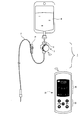
- FIG. 1 shows a state in which the infusion bag B is suspended from an infusion stand (not shown).
- the main body 3 (first embodiment) is attached to an infusion tube S connected to the infusion bag B.
- the size of the main body 3 is compact and lightweight, can be easily attached to the drip tube S, and does not add a significant weight to the drip tube S.
- the main body 3 is provided with a holding portion 5 attached to the drip tube S. Moreover, the main body 3 has a housing specification, and is composed of a holding part 5 side and a container part 7 side.
- Reference numerals 9 and 9 are a light projecting part and a light receiving part which constitute the drip detection part, which are inserted into the embedding part 5 side and arranged opposite to each other. In the above-described holding state, the light projecting unit 9 and the light receiving unit 9 are opposed to each other with the drip tube S interposed therebetween, and when there is a drip, the droplet passes therethrough. . Since the light changes depending on whether or not it passes through the droplet, the drop of the infusion solution is detected using the change.
- Reference numeral 11 denotes a battery
- reference numeral 13 denotes a substrate. The battery 11 and the substrate 13 are accommodated in the container portion 7.
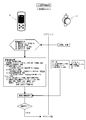
- the electrical configuration of the main body 3 is as shown in FIG. 3, and a microcomputer including a CPU, a memory, a timer, and the like is mounted on the substrate 13. The whole is controlled by the CPU.
- the CPU is connected to an infusion detection unit 9, a lighting circuit 12, and a shake detection sensor (three-axis acceleration sensor) 15, and receives information from the infusion detection unit 9 and the shake detection sensor 15, and also controls state display.
- the state display LED 14 can be blinked by controlling the lighting circuit 12.
- the status display LED 14 is a three-color LED composed of a red LED, a green LED, and a blue LED, and can be lit in each color. In FIG. 2, the status display LED 14 is not shown.
- Bluetooth (registered trademark) 17 is used as a wireless communication function.
- the power supply (power supply) 19 is composed of a lithium ion battery, and supplies power to each part under battery control.
- the communication partner of the main body 3 is a dedicated portable device 21.
- the portable device 21 is provided with a CPU, a memory, and the like, and the CPU controls the whole.
- the CPU includes an operation button (operation unit) 23 (a dose increment button ( ⁇ ) and a decrement button ( ⁇ ), a time increment button ( ⁇ ) and a decrement button ( ⁇ ), A center confirmation button) and an LCD (display) 25 as a display unit are connected to receive input information through the operation of the operation buttons 23 and display the screen on the LCD 25.
- Bluetooth (registered trademark) 27 is provided as a wireless communication function.
- a power supply (power supply) 29 is externally charged via a USB terminal, and supplies power to each unit under battery control.
- the main body 3 side and the portable device 21 side have the above-described hardware configuration, and various functional units are realized by the CPUs executing dedicated programs stored in the memory through communication.
- an “infusion state monitoring unit” is realized on the main body 3 side.
- the “drip condition monitoring unit” starts counting the number of drip and starts an addition timer to start the drip elapsed time (in other words, the first drip status). Start the measurement of the time that has passed since then. Furthermore, for each drip count, the drip interval time (in other words, the time elapsed from the last drop to the next drop) is measured.
- the infusion elapsed time and the number of infusions are data stored in the memory and increase with the passage of time, so the data is incrementally updated.
- the drip interval time is basically a content for sequential display, and when the next drip is detected, the data is overwritten and updated.
- a “screen control processing unit” is realized on the mobile device 21 side.
- This “screen control processing unit” creates a screen to be displayed on the LCD 25, and has a midway correction function.
- the screen created by the “screen control processing unit” is displayed on the LCD 25.
- a “forced cutting part” in the case of successful infusion is realized.
- the operation of the drip management system 1 having the above-described configuration will be described according to the drip procedure.
- the operation in ⁇ initial alignment> in the drip preparation stage will be described with reference to FIG. ⁇ ⁇ Initial alignment> at the drip preparation stage ⁇ ⁇ Nurse>
- the infusion bag B is suspended from an infusion stand and the patient is inserted. Further, the main body 3 is attached to the drip tube S. The main body 3 is always turned on. Thereafter, the nurse turns on the portable device 21 to bring it closer to the main body 3.
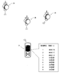
- ⁇ Mobile device-> Main unit> The portable device 21 searches for a pairing partner (via Bluetooth (registered trademark)). The main body 3 always sends an ID except when the pairing is established.
- a registration list is created as a pairing partner candidate as shown in FIG. To do.
- the registration order is set so that the one with the higher radio field strength comes up. Therefore, when a plurality of main bodies 3A, 3B, 3C are in the search range, any main body 3A, 3B, 3C is listed, but the order depends on the distance between the mobile device 21 and the main bodies 3A, 3B, 3C. It will be decided.
- the partner determination unit causes the status display LED 14 of the main body 3 to blink in yellow from the one with the highest registration order every time the confirmation button 23 is confirmed to be pressed. Then, pairing with the main body 3 is (temporarily) established.
- pairing with the main body 3B is (provisionally) established, and if it is twice (when there is a second press within 3 seconds from the first time), pairing with the main body 3C (temporary) ) If it is established 3 times (when there is a second press within 3 seconds from the first time and a third press within 3 seconds from the second time), pairing with the main body 3A is (provisionally) established. It will be. If the next press of the confirm button 23 cannot be confirmed within 3 seconds, the (provisional) establishment is set to (real) establishment. When the long press of the confirm button 23 is confirmed, the registration list is deleted, and the search for a pairing partner is started again.
- ⁇ Nurse> The nurse operates the confirm button 23 so as to blink the status display LED 14 of the main body 3 for the intended patient.
- the partner determining unit establishes pairing according to the determination procedure described above. It is often the case that infusion is performed on multiple patients simultaneously in one room, but by using the registration list format of this partner determination unit, pairing with the correct partner in a short time is possible. It is possible.
- the screen control processing unit on the portable device 21 side operates to request the main body 3 to confirm the state. If the state on the main body 3 side is [initial] (a state in which various data is reset), the operation button 23 is in a setting input enabled state, and a screen for prompting input on the LCD 25 is displayed.
- the nurse operates the operation button 23 based on an instruction from the doctor, and for initial setting, (1) infusion set ( ⁇ drops / ml), (2) dose ( ⁇ ml), (3) Enter the administration time (Oh00m), (4) drop size (standard or large). For (1) infusion set ( ⁇ drops / ml) and (4) drop size (standard or large), there is no dedicated button, and either button is substituted.
- the infusion interval time data is sequentially received from the main unit 3 side for display. Are created each time and displayed on the LCD 25.
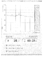
- the moving image screen is shown in FIG. 6 and is actually a color image, but will be described based on a diagram for the sake of visual recognition.
- the background is black.
- dots (white) of the dot row 31 are displayed so as to draw a circular trajectory line. This dot row 31 shows a time axis of one loop, and one loop, that is, one round, is the target drip interval.
- the dot row in the upper arc-shaped portion is a dot row 31 G in an appropriate range, and the dots are displayed in green and distinguished.
- This appropriate range is obtained by adding or subtracting a predetermined range to the target drip interval to give a width.
- One dot 31F is displayed in blue as a previous display dot to be described later.
- a thick drip interval display band (line) 33 is superimposed and drawn from the upper center to the right side of the dot row 31.
- the start point 33A of the drip interval display band 33 overlaps the dot that is the center of the dot row 31G in the appropriate range.
- the remaining end point is the end point (red) 33B.
- the total length of the drip interval display band 33 indicates the drip interval, and the end point 33B side overlaps the dot row 31 and is displayed as a moving image extending clockwise according to the loop speed described above.
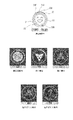
- the screen control processing unit also has a determination function, and classifies the immediately preceding infusion interval into three types (fast, appropriate, and slow). This classification result is reflected on the screen by the human face and the face color of the face image 35. This face image 35 is displayed as a status display mark.
- the drip interval display band 33 is similarly color-coded. Colors are used properly: early (yellow), appropriate (green), and slow (purple).
- a line (green) 37 indicating the target value range is displayed on the upper side of the dot row 31G indicating the appropriate range, and the drip interval display band 33 is superimposed on the dot row 31G in the appropriate range. , It can always be confirmed by the line display.
- FIGS. 6A and 6B shows the middle of the drip interval display band 33 extending, but (within an appropriate range) means the immediately preceding result, and the previous display dot 31F is a dot in the appropriate range.
- the face image 35 is also smiling (appropriate).
- the drip interval display band 33 is also displayed in green (appropriate color). (In the case of early) means the immediately preceding result, the previous display dot 31F is in front of the dot row 31G in the appropriate range, and the face image 35 is also a confused face (early).
- the drip interval display band 33 is also displayed in yellow (fast).
- the screen control processing unit sequentially receives the data from the main body 3 and creates a screen. Will transition. ⁇ Nurse> The nurse can make the next adjustment with reference to the extension speed of the drip interval display band 33 indicating the current result as well as the position of the face image 35 and the previous display dot 31F indicating the previous result, It is easy to adjust to the appropriate range.
- pairing is established in the same manner.
- the screen control processing unit on the portable device 21 side operates and requests the main body 3 to confirm the state.
- the loop speed condition that is, looping around the loop at a speed of 2.9 s / lap
- the change to this condition means that the infusion interval was later than the initial expectation due to the change in the patient's body position on the way. On the way, by changing to this condition, the infusion can be terminated using the entire prescribed administration time while minimizing fluctuations in the infusion interval.
- the screen of FIG. 6 is displayed on the LCD 25 of the portable device 21, but is displayed based on the corrected content. Therefore, when the drip interval is 3.0 s, this time, a slow display is made.
- ⁇ Nurse> The nurse's matching work is the same as the initial matching stage.
- Mobile device> The mobile device 21 side also forcibly disconnects the pairing when the midway alignment is completed, as in the initial alignment stage.
- the portable device 21 automatically responds to the changed situation, so the nurse can set the drip interval in the same operation as the initial setting stage. Can be matched.
- the data stored in the memory on the main body 3 side is reset and the timer is reset to return to [initial] by a reset request from the portable device 21 side. . This reset operation enables the next use for another patient.
- the drip status monitoring unit of the main body 3 is provided with a function that prevents detection. Even if there is dripping, the drip detection unit 9 may not be able to detect it. For example, when a patient moves to a toilet or the like, he / she walks up from a bed or transfers to a wheelchair, and in that case, the drip tube S may be shaken and become oblique. In that case, the infusion solution drops along the wall of the cylinder, so that the droplet does not pass between the light projecting unit and the light receiving unit, and cannot be detected by the drip detection unit 9 even if it actually drops.
- the drip condition monitoring unit starts counting the number of infusions when the drip detection unit 9 notifies the detection of the first drip. This is a “normal count”.
- the addition by the “normal count” is ignored during the period, and the addition by the “pseudo count” is replaced.
- the transition from the “normal count” mode to the “pseudo count” mode and the (return) transition from the “pseudo count” mode to the “normal count” mode are in accordance with the shake detection routine shown in FIG. That is, when the shaking detection sensor 15 detects shaking, the “pseudo count” is started.
- This “pseudo-count” uses the drip interval time stored immediately before. As described above, the drip interval time is content for sequential display, and when the next drip is detected, the data is overwritten and updated, but the data of the drip interval time immediately before this is used.
- the subtraction timer (set for 5 minutes) is turned ON for warning and subtraction is started.
- the subtraction timer times out, it is determined that the patient's action period has exceeded the action period with normal shaking, that is, an abnormal situation has occurred, and the status display LED 14 blinks red to issue a warning to the surroundings. .
- This subtraction timer is reset when shaking can no longer be detected.
- the portable device 21 is a dedicated device, a smartphone can also be used as shown in FIG.
- the operation unit is a touch panel type.
- a smartphone is a small personal computer, and history processing using the function is possible. For example, if the number of infusions per minute is recorded in chronological order on the main body 3 side, the smartphone side requests transfer of the data, and a graph showing the change in flow rate is displayed as shown in FIG. It is also possible to make it. Since the infusion history of the patient can be confirmed from this graph, the infusion situation of the patient can be grasped in detail in time series. It is also easy to update and display the remaining dose and the remaining administration time sequentially.
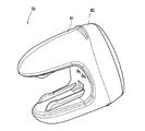
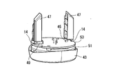
- FIG. 11 and 12 show a main body 39 (second embodiment) different from that shown in FIG.
- the housing of the main body 39 is composed of a holding part 41 side and a container part 43 side.
- a point light source 45, reflecting mirrors 47 and 47, and a light receiving element 49 are provided inside.
- a substrate 53 is provided on the upper side of the battery case 51, and a pair of status display LEDs 14 and 14 are disposed on the upper surface of the substrate 53. These LEDs 14 and 14 are on the back side of the reflecting mirrors 47 and 47, and even if they blink, they do not interfere with detection.
- the measurement value of the infusion interval time is set as the actual infusion interval, and the actual infusion interval is appropriate and too early depending on the difference from the infusion interval to the target infusion interval.
- a determination function for determining too late is also provided. This determination function is the same as the determination function provided in the screen control processing unit on the portable device 21 side, and classifies the immediately preceding drip interval into three types (fast, appropriate, and slow). This classification result is reflected in the lighting color of the status display LEDs 14 and 14. The colors are used appropriately for early (blue), proper (green), and slow (purple).
- the lighting time is a short time of about 60 msec.
- the lighting of the status display LED 14 can be confirmed from the outside.
- the point that the status display LED 14 of the main body 39 blinks from the higher registration order every time the partner determining unit on the mobile device 21 side confirms the pressing of the confirmation button 23 based on the registration list is the same as the main body 3.
- the lighting colors are different as described above, and the state of the drip can be easily visually confirmed simply by looking at the lighting colors of the status display LEDs 14 and 14 of the main body 39. Therefore, from the vicinity of the entrance of the hospital room, etc., the lighting color is confirmed, and only when the color is blue (early) or purple (slow), the patient moves closer to the patient and the status is displayed on the portable device 21 to make the adjustment work as described above. It is enough to do. Therefore, the labor of the nurse can be reduced. Moreover, since the state of infusion can be easily confirmed, the safety of infusion can be improved.
- the specific configuration of the present invention is not limited to the above-described embodiments, and even if there is a design change within a scope not departing from the gist of the present invention.
- the shapes of the main bodies 3 and 39 and the portable device 21 are not particularly limited, and the size and design of various images on the display screen may be any as long as they can perform the required functions.
Landscapes
- Health & Medical Sciences (AREA)
- Vascular Medicine (AREA)
- Engineering & Computer Science (AREA)
- Anesthesiology (AREA)
- Biomedical Technology (AREA)
- Heart & Thoracic Surgery (AREA)
- Hematology (AREA)
- Life Sciences & Earth Sciences (AREA)
- Animal Behavior & Ethology (AREA)
- General Health & Medical Sciences (AREA)
- Public Health (AREA)
- Veterinary Medicine (AREA)
- Infusion, Injection, And Reservoir Apparatuses (AREA)
Abstract
Priority Applications (1)
| Application Number | Priority Date | Filing Date | Title |
|---|---|---|---|
| JP2018505952A JP6893035B2 (ja) | 2016-03-16 | 2017-03-14 | 点滴管理システム |
Applications Claiming Priority (2)
| Application Number | Priority Date | Filing Date | Title |
|---|---|---|---|
| JP2016052888 | 2016-03-16 | ||
| JP2016-052888 | 2016-03-16 |
Publications (1)
| Publication Number | Publication Date |
|---|---|
| WO2017159683A1 true WO2017159683A1 (fr) | 2017-09-21 |
Family
ID=59851045
Family Applications (1)
| Application Number | Title | Priority Date | Filing Date |
|---|---|---|---|
| PCT/JP2017/010211 Ceased WO2017159683A1 (fr) | 2016-03-16 | 2017-03-14 | Système de gestion de perfusion |
Country Status (2)
| Country | Link |
|---|---|
| JP (1) | JP6893035B2 (fr) |
| WO (1) | WO2017159683A1 (fr) |
Cited By (4)
| Publication number | Priority date | Publication date | Assignee | Title |
|---|---|---|---|---|
| JP2019177131A (ja) * | 2018-03-30 | 2019-10-17 | 株式会社ジェイ・エム・エス | 流量監視装置、輸液装置及び異常報知方法 |
| KR20200105096A (ko) * | 2019-02-28 | 2020-09-07 | 안동과학대학교 산학협력단 | 수액주사를 맞는 도중에 수액주머니를 휴대하는 장치 및 그 구성방법 |
| CN111936181A (zh) * | 2018-03-20 | 2020-11-13 | 贝克顿·迪金森公司 | 用于输送流体的医疗输注泵 |
| JP2024166270A (ja) * | 2018-12-31 | 2024-11-28 | ベクトン・ディキンソン・アンド・カンパニー | ウェアラブル医療デバイスのユーザへの通知を強化するための、システム、装置、および方法 |
Citations (5)
| Publication number | Priority date | Publication date | Assignee | Title |
|---|---|---|---|---|
| JPH08191891A (ja) * | 1995-01-18 | 1996-07-30 | Seitetsuku Kk | 点滴量制御方法及び点滴量制御装置 |
| US6083206A (en) * | 1994-12-07 | 2000-07-04 | Midex Marketing Limited | Intravenous infusion flow rate monitoring device |
| JP2009240428A (ja) * | 2008-03-28 | 2009-10-22 | Shizuoka Prefecture | 点滴計測システム |
| JP3194008U (ja) * | 2014-08-20 | 2014-10-30 | 株式会社トライテック | 携帯型点滴用ドリップカウンタ |
| JP2015534838A (ja) * | 2012-10-15 | 2015-12-07 | エイス メディカル カンパニー,リミテッド | 落下方式による注入量の自動調節方法及びこのための装置 |
Family Cites Families (2)
| Publication number | Priority date | Publication date | Assignee | Title |
|---|---|---|---|---|
| US4718896A (en) * | 1986-01-10 | 1988-01-12 | Abbott Laboratories | Apparatus and method for controlling the flow of fluid through an administration set |
| KR20150125484A (ko) * | 2014-04-30 | 2015-11-09 | 주식회사한빛엠디 | 수액유량 자동 조절장치 및 수액유량 자동 조절방법 |
-
2017
- 2017-03-14 JP JP2018505952A patent/JP6893035B2/ja active Active
- 2017-03-14 WO PCT/JP2017/010211 patent/WO2017159683A1/fr not_active Ceased
Patent Citations (5)
| Publication number | Priority date | Publication date | Assignee | Title |
|---|---|---|---|---|
| US6083206A (en) * | 1994-12-07 | 2000-07-04 | Midex Marketing Limited | Intravenous infusion flow rate monitoring device |
| JPH08191891A (ja) * | 1995-01-18 | 1996-07-30 | Seitetsuku Kk | 点滴量制御方法及び点滴量制御装置 |
| JP2009240428A (ja) * | 2008-03-28 | 2009-10-22 | Shizuoka Prefecture | 点滴計測システム |
| JP2015534838A (ja) * | 2012-10-15 | 2015-12-07 | エイス メディカル カンパニー,リミテッド | 落下方式による注入量の自動調節方法及びこのための装置 |
| JP3194008U (ja) * | 2014-08-20 | 2014-10-30 | 株式会社トライテック | 携帯型点滴用ドリップカウンタ |
Cited By (9)
| Publication number | Priority date | Publication date | Assignee | Title |
|---|---|---|---|---|
| CN111936181A (zh) * | 2018-03-20 | 2020-11-13 | 贝克顿·迪金森公司 | 用于输送流体的医疗输注泵 |
| JP2021517017A (ja) * | 2018-03-20 | 2021-07-15 | ベクトン・ディキンソン・アンド・カンパニーBecton, Dickinson And Company | 流体の送達のための医療用注入ポンプ |
| US11642461B2 (en) | 2018-03-20 | 2023-05-09 | Becton, Dickinson And Company | Medical infusion pump for delivery of a fluid |
| JP7599337B2 (ja) | 2018-03-20 | 2024-12-13 | ベクトン・ディキンソン・アンド・カンパニー | 流体の送達のための医療用注入ポンプ |
| JP2019177131A (ja) * | 2018-03-30 | 2019-10-17 | 株式会社ジェイ・エム・エス | 流量監視装置、輸液装置及び異常報知方法 |
| JP2024166270A (ja) * | 2018-12-31 | 2024-11-28 | ベクトン・ディキンソン・アンド・カンパニー | ウェアラブル医療デバイスのユーザへの通知を強化するための、システム、装置、および方法 |
| JP7809177B2 (ja) | 2018-12-31 | 2026-01-30 | ベクトン・ディキンソン・アンド・カンパニー | ウェアラブル医療デバイスのユーザへの通知を強化するための、システム、装置、および方法 |
| KR20200105096A (ko) * | 2019-02-28 | 2020-09-07 | 안동과학대학교 산학협력단 | 수액주사를 맞는 도중에 수액주머니를 휴대하는 장치 및 그 구성방법 |
| KR102207495B1 (ko) * | 2019-02-28 | 2021-01-25 | 안동과학대학교 산학협력단 | 수액주사를 맞는 도중에 수액주머니를 휴대하는 장치 및 그 구성방법 |
Also Published As
| Publication number | Publication date |
|---|---|
| JP6893035B2 (ja) | 2021-06-23 |
| JPWO2017159683A1 (ja) | 2019-01-24 |
Similar Documents
| Publication | Publication Date | Title |
|---|---|---|
| US12064591B2 (en) | Infusion pump system and method | |
| EP1924307B1 (fr) | Dispositif de commande manuel pour pompe a perfusion | |
| US8663201B2 (en) | Infusion device | |
| WO2017159683A1 (fr) | Système de gestion de perfusion | |
| US9375569B2 (en) | Controller unit for a functional electrical stimulation (FES) orthotic system | |
| US20170136297A1 (en) | Fitness monitoring device | |
| CN204819530U (zh) | 仿生家政服务机器人 | |
| US20070060870A1 (en) | Controller device for an infusion pump | |
| US20070093786A1 (en) | Watch controller for a medical device | |
| KR20090102264A (ko) | 웨어러블 측정 장치 | |
| DK178729B1 (en) | Positioning device for determining and recording an injection site | |
| CN204976639U (zh) | 家政服务机器人 | |
| JP3194008U (ja) | 携帯型点滴用ドリップカウンタ | |
| KR101337332B1 (ko) | 무선 충전하는 모바일 감성 센싱장치 및 충전방법 | |
| CN204637551U (zh) | 具有提醒功能的玩具 | |
| US12508365B2 (en) | Site tracking based on connectivity in infusion pump systems | |
| JP3784048B2 (ja) | セパレート型光通信生体計測装置 | |
| EP4473542A1 (fr) | Dispositif de livraison interrogeable et module d'état associé | |
| CN116612616A (zh) | 一种防止患者呛咳的吞咽训练系统及方法 | |
| TWM515793U (zh) | 健康管理鞋 | |
| HK1224611B (en) | Infusion pump system and method |
Legal Events
| Date | Code | Title | Description |
|---|---|---|---|
| DPE1 | Request for preliminary examination filed after expiration of 19th month from priority date (pct application filed from 20040101) | ||
| ENP | Entry into the national phase |
Ref document number: 2018505952 Country of ref document: JP Kind code of ref document: A |
|
| NENP | Non-entry into the national phase |
Ref country code: DE |
|
| 121 | Ep: the epo has been informed by wipo that ep was designated in this application |
Ref document number: 17766681 Country of ref document: EP Kind code of ref document: A1 |
|
| 32PN | Ep: public notification in the ep bulletin as address of the adressee cannot be established |
Free format text: NOTING OF LOSS OF RIGHTS PURSUANT TO RULE 112(1) EPC (EPO FORM 1205A DATED 12/12/2018) |
|
| 122 | Ep: pct application non-entry in european phase |
Ref document number: 17766681 Country of ref document: EP Kind code of ref document: A1 |