WO2017159811A1 - 回転電機及び回転電機の製造方法 - Google Patents
回転電機及び回転電機の製造方法 Download PDFInfo
- Publication number
- WO2017159811A1 WO2017159811A1 PCT/JP2017/010748 JP2017010748W WO2017159811A1 WO 2017159811 A1 WO2017159811 A1 WO 2017159811A1 JP 2017010748 W JP2017010748 W JP 2017010748W WO 2017159811 A1 WO2017159811 A1 WO 2017159811A1
- Authority
- WO
- WIPO (PCT)
- Prior art keywords
- protrusion
- inclined surface
- radial direction
- contact surface
- contact
- Prior art date
- Legal status (The legal status is an assumption and is not a legal conclusion. Google has not performed a legal analysis and makes no representation as to the accuracy of the status listed.)
- Ceased
Links
Images




Classifications
-
- H—ELECTRICITY
- H02—GENERATION; CONVERSION OR DISTRIBUTION OF ELECTRIC POWER
- H02K—DYNAMO-ELECTRIC MACHINES
- H02K1/00—Details of the magnetic circuit
- H02K1/06—Details of the magnetic circuit characterised by the shape, form or construction
- H02K1/12—Stationary parts of the magnetic circuit
- H02K1/14—Stator cores with salient poles
- H02K1/146—Stator cores with salient poles consisting of a generally annular yoke with salient poles
- H02K1/148—Sectional cores
-
- H—ELECTRICITY
- H02—GENERATION; CONVERSION OR DISTRIBUTION OF ELECTRIC POWER
- H02K—DYNAMO-ELECTRIC MACHINES
- H02K1/00—Details of the magnetic circuit
- H02K1/06—Details of the magnetic circuit characterised by the shape, form or construction
- H02K1/12—Stationary parts of the magnetic circuit
- H02K1/18—Means for mounting or fastening magnetic stationary parts on to, or to, the stator structures
-
- H—ELECTRICITY
- H02—GENERATION; CONVERSION OR DISTRIBUTION OF ELECTRIC POWER
- H02K—DYNAMO-ELECTRIC MACHINES
- H02K15/00—Processes or apparatus specially adapted for manufacturing, assembling, maintaining or repairing of dynamo-electric machines
- H02K15/02—Processes or apparatus specially adapted for manufacturing, assembling, maintaining or repairing of dynamo-electric machines of stator or rotor bodies
- H02K15/021—Magnetic cores
-
- H—ELECTRICITY
- H02—GENERATION; CONVERSION OR DISTRIBUTION OF ELECTRIC POWER
- H02K—DYNAMO-ELECTRIC MACHINES
- H02K2201/00—Specific aspects not provided for in the other groups of this subclass relating to the magnetic circuits
- H02K2201/15—Sectional machines
-
- H—ELECTRICITY
- H02—GENERATION; CONVERSION OR DISTRIBUTION OF ELECTRIC POWER
- H02K—DYNAMO-ELECTRIC MACHINES
- H02K2213/00—Specific aspects, not otherwise provided for and not covered by codes H02K2201/00 - H02K2211/00
- H02K2213/03—Machines characterised by numerical values, ranges, mathematical expressions or similar information
Definitions
- the disclosed embodiment relates to a rotating electrical machine and a method for manufacturing the rotating electrical machine.
- Patent Document 1 describes a stator of a rotating electrical machine in which irregularities that engage with each other in contact portions of adjacent laminated iron cores are formed.
- This invention is made in view of such a problem, and it aims at providing the manufacturing method of the rotary electric machine which can make it difficult to produce a clearance gap between the contact surfaces of an iron core piece, and a rotary electric machine.
- a contact surface along a radial direction with respect to the rotation axis is provided at one end and the other end in the circumferential direction around the rotation axis.
- a recessed portion that is provided on the contact surface of the side end portion includes a second inclined surface that contacts the first inclined surface on the outer side and the inner side in the radial direction, and accommodates the protruding portion of the adjacent iron core piece;
- the cross-sectional shape of the protrusion perpendicular to the rotation axis is centered on a first end of the contact surface in the radial direction and is opposite to the first end of the protrusion.
- the distance between the second end portion on the distal end side of the first inclined surface located at the first end portion is a radius.
- said first end rotary electric machine at least a portion of said first inclined surface has a shape in contact with the second inclined surface positioned on the opposite side is applied.
- the one end and the other end in the circumferential direction around the rotation axis are provided with contact surfaces along the radial direction with respect to the rotation axis, and the stator core is provided.
- a concave portion that is provided on the contact surface includes a second inclined surface that contacts the first inclined surface on the outer side and the inner side in the radial direction, and accommodates the protruding portion of the adjacent iron core piece, and the protrusion
- the cross-sectional shape perpendicular to the rotation axis of the portion is such that the radial dimension of the proximal end portion of the protruding portion is L1, and the first end portion on one side in the radial direction of the contact surface and the protruding portion The distance in the radial direction is L2, the contact surface of the protru
- L3 (L1 + L2) sin2 ⁇ , where L3 is the protrusion dimension of L, and the inclination angle of the first inclined surface located on the side opposite to the first end of the protrusion is ⁇ .
- a rotating electric machine having a shape is applied.
- a method for manufacturing the rotating electric machine wherein a plurality of core pieces are connected in a ring shape to form a stator core, and a frame is formed outside the stator core. A method of manufacturing a rotating electric machine is applied.
- the one end and the other end in the circumferential direction around the rotation axis are provided with contact surfaces along the radial direction with respect to the rotation axis, and the stator core A plurality of iron core pieces, a tapered projecting portion provided on the contact surface of the one side end portion and having a first inclined surface on the outer side and the inner side in the radial direction, and the other side end portion A concave portion that is provided on the contact surface, includes a second inclined surface that contacts the first inclined surface on the outer side and the inner side in the radial direction, and accommodates the protruding portion of the adjacent iron core piece;
- a rotating electrical machine having a means for preventing rotation of the protruding portion with respect to the recess with the first end portion on the outer side or the inner side in the radial direction as the rotation center is applied.
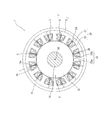
- FIG. 2 is a cross-sectional view taken along the line II-II in FIG. 1 illustrating an example of the overall configuration of the rotating electrical machine according to the first embodiment.
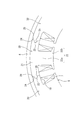
- It is explanatory drawing which extracts and represents a part of stator iron core.
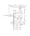
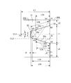
- It is explanatory drawing showing an example of the cross-sectional shape perpendicular
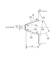
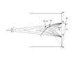
- It is explanatory drawing showing that the 1st inclined surface of a protrusion part hits the 2nd inclined surface of a recessed part inside the circle centering on a 1st edge part when a bending stress acts.
- FIGS. 1 and 2 are axial sectional views showing an example of the overall configuration of the rotating electrical machine 1
- FIG. 2 is a transverse sectional view taken along the line II-II of FIG.
- the rotating electrical machine 1 includes a stator 2, a rotor 3, a frame 4, a load side bracket 11, and an anti-load side bracket 13.
- the rotating electrical machine 1 is used as a motor or a generator.
- the rotor 3 includes a shaft 10, a rotor core 15 provided on the outer periphery of the shaft 10, and a plurality of permanent magnets (not shown) disposed on the rotor core 15.
- the rotor core 15 is configured by laminating a plurality of electromagnetic steel plates in the axial direction, and is disposed so as to face the stator 2 in the radial direction.
- the load side bracket 11 is fixed to the load side (right side in FIG. 1) of the frame 4, and the anti-load side bracket 13 is fixed to the anti-load side (left side in FIG. 1) of the frame 4.
- the shaft 10 is rotatably supported around the rotation axis AX by a load side bearing 12 provided on the load side bracket 11 and an antiload side bearing 14 provided on the antiload side bracket 13.
- the “load side” refers to the direction in which a load is attached to the rotating electrical machine 1, that is, the direction in which the shaft 10 protrudes (right side in FIG. 1) in this example. It points in the opposite direction to the load side (left side in FIG. 1).
- axial direction refers to the direction along the rotational axis AX of the shaft 10 (rotor 3)
- circumferential direction refers to the circumferential direction around the rotational axis AX
- diameter refers to a radial direction around the rotation axis AX.
- the stator 2 is disposed on the inner peripheral side of the frame 4 so as to face the rotor 3 in the radial direction.
- the stator 2 includes a stator core 5 provided on an inner peripheral surface of the frame 4, a bobbin 6 attached to the stator core 5, a winding 7 wound around the bobbin 6, and a resin portion 8.
- the bobbin 6 is made of an insulating material in order to electrically insulate the stator core 5 and the winding 7 from each other.
- the bobbin 6 may be a sheet-like insulator.
- the stator core 5 is configured by combining a plurality (12 pieces in the illustrated example) of core pieces 20 (also referred to as divided cores) in the circumferential direction.
- Each iron core piece 20 is configured by, for example, a plurality of electromagnetic steel plates formed in a predetermined shape by press punching and stacked in the axial direction.
- the iron core piece 20 has a substantially arc-shaped yoke portion 21 and a teeth portion 22 provided integrally with the yoke portion 21.
- the teeth part 22 is provided with a main body part 22a provided so as to protrude radially inward from the yoke part 21, and a widened part 22b provided at the front end on the inner peripheral side of the main body part 22a and having an increased circumferential width. And have. In the example shown in FIG. 2, the tips of adjacent widened portions 22b are separated in the circumferential direction, but may be in contact with each other.
- Each core piece 20 is connected in the circumferential direction after the bobbin 6 and the winding 7 are mounted on the tooth portion 22 to form the stator core 5. Then, after the stator core 5 is fixed to the inner peripheral surface of the frame 4 by press fitting or shrink fitting, it is molded with resin. As a result, as shown in FIG. 1, the stator core 5 (iron core piece 20), the bobbin 6 and the winding 7 are integrally fixed by a resin portion 8 made of resin.
- the windings 7 attached to the respective tooth portions 22 are accommodated in the slot portions 19 between the teeth portions 22 adjacent in the circumferential direction, and the opposite sides of the winding layers of the windings 7.
- the parts are arranged with a gap 19a therebetween. Resin is pressed into the gap 19a at the time of molding, and the resin portion 8 is filled.
- substantially annular projecting portions 8a and 8b are formed on the load side end portion and the anti-load side end portion of the resin portion 8, respectively. These protrusions 8a and 8b are inlay-fitted to the load side bracket 11 and the anti-load side bracket 13, respectively.
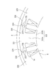
- FIG. 3 is an explanatory view showing a part of the stator core 5 extracted.
- illustration of the bobbin 6 and the resin part 8 is abbreviate
- the iron core piece 20 has an arcuate yoke portion 21 and a teeth portion 22.
- the teeth part 22 has a main body part 22a and a widened part 22b.
- Each iron core piece 20 has contact surfaces 24 and 26 along the radial direction in contact with adjacent iron core pieces 20 at both ends in the circumferential direction.
- a protrusion 23 is provided on the contact surface 24 at the end on one side (left side in FIG. 3) in the circumferential direction, and a recess is formed on the contact surface 26 on the other end (right side in FIG. 3) in the circumferential direction. 25 is provided.
- the core pieces 20 adjacent to each other in the circumferential direction are connected in a state where the protruding portions 23 of the core pieces 20 adjacent to the recesses 25 are accommodated and the contact surfaces 24 and 26 are in contact with each other.
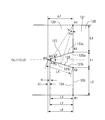
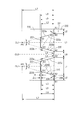
- FIG. 4 is an explanatory diagram illustrating an example of a cross-sectional shape perpendicular to the axial direction of the protruding portion 23 and the recessed portion 25 of the iron core piece 20.
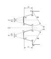
- FIG. 5 is an explanatory diagram showing that the first inclined surface of the protrusion hits the second inclined surface of the recess when bending stress is applied.
- the protruding portion 23 and the recessed portion 25 are provided at the center position in the radial direction of the yoke portion 21. That is, the combined center line CL1 of the protruding portion 23 and the recessed portion 25 substantially coincides with the yoke center line CL0 that is the center line in the radial direction of the yoke portion 21.
- the combination center line CL1 passes through a reference position P0 where an extension line of first inclined surfaces 23a and 23b (second inclined surfaces 25a and 25b), which will be described later, is parallel, and is parallel to the normal direction of the contact surfaces 24 and 26. Is a line.
- the protrusion 23 is formed in a tapered shape in which the radial width decreases toward the tip, in this example, isosceles trapezoidal shape, and includes first inclined surfaces 23 a and 23 b on the outer side and the inner side in the radial direction. .
- the first inclined surfaces 23a and 23b are inclined by a contact angle ⁇ with respect to the combination center line CL1.
- the recess 25 is an isosceles trapezoidal recess that is substantially the same shape as the protrusion 23, and includes second inclined surfaces 25a and 25b on the outer side and the inner side in the radial direction.
- the second inclined surfaces 25a and 25b are inclined by a contact angle ⁇ with respect to the combination center line CL1.
- the concave portion 25 of the iron core piece 20 accommodates the protruding portion 23 of the adjacent iron core piece 20 in a state where the second inclined surfaces 25a and 25b are in contact with the first inclined surfaces 23a and 23b of the protruding portion 23, respectively.
- the cross-sectional shape perpendicular to the axial direction of the protruding portion 23 is set as follows. That is, as shown in FIGS. 4 and 5, the projecting portion 23 is positioned on the opposite side of the projecting portion 23 from the first end A ⁇ b> 1 around the first end A ⁇ b> 1 on the outer side in the radial direction of the contact surface 24.
- the first inclined surface 23b has a shape in contact with the second inclined surface 25b on the inner side of a circle CA having a radius RA with the distance RA between the first inclined surface 23b and the second end A3 on the distal end side.
- the protrusion 23 is centered on the first end B1 on the inner side in the radial direction of the contact surface 24, and is located on the tip side of the first inclined surface 23a located on the opposite side of the first end B1 of the protrusion 23.
- the first inclined surface 23a has a shape in contact with the second inclined surface 25a inside the circle CB whose radius is the distance RB between the second end B3 and the first end B1.
- the third end A2 on the base end side of the first inclined surface 23b of the protrusion 23 is located on the circumference of the circle CA. Further, the third end B2 on the base end side of the first inclined surface 23a of the protrusion 23 is located on the circumference of the circle CB.
- the projecting portion 23 has the above-described cross-sectional shape and the projecting portion 23 and the recessed portion 25 are connected, even when a bending force with the first end A1 or the first end B1 as a fulcrum acts, It has a structure in which a gap is hardly generated between the contact surfaces 24 and 26 of the adjacent iron core pieces 20.
- the cross-sectional shape will be described more specifically.
- the fulcrum when the contact surfaces 24 and 26 of the adjacent core pieces 20 are to be opened is the first end A1 or the first end B1. Considering the case of opening the first end A1 as a fulcrum, the following condition may be satisfied to prevent the opening.
- the radial dimension (dimension between the third end portions B2 and A2) of the base end portion of the projecting portion 23 is L1
- the radial distance between the first end portions A1 and B1 and the projecting portion 23 is L2.
- L1 + 2L2 is the thickness of the yoke portion 21 in the radial direction.
- L1 and L2 are arbitrary lengths.
- This protrusion dimension L3 is the basis of the height of the protrusion 23.
- the actual height of the protrusion 23 is a dimension obtained by adding the radius R of the corner to the L3. It becomes.
- the coefficient ⁇ takes into account the dimensional variation due to the lamination of the steel sheets of the core pieces 20, and it is preferable that the radius R is added by several% to about 30% (for example, ⁇ ⁇ 1.3).
- the “projection dimension from the contact surface of the projecting portion” substantially includes not only the projecting dimension L3 but also the projecting dimension L5.
- the first inclined surfaces 23 a and 23 b and the second inclined surfaces 25 a and 25 b, and the contact surface 24 and the contact surface 26 are reliably in contact between the tip portion of the protruding portion 23 and the bottom portion of the recess 25.
- a minute gap for example, about 10 ⁇ m
- the depth L6 from the contact surfaces 24 and 26 of the recess 25 is defined as ⁇ L as the gap.
- L6 L5 + ⁇ L It becomes.
- the combination center line CL1 of the protrusion 23 and the recess 25 is located on the yoke center line CL0. Therefore, the same applies to the bending stress with the first end B1 as a fulcrum.
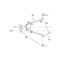
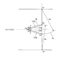
- FIG. 6 shows a circle CB having a radius RB with the first end B1 as a fulcrum.
- the contact angle ⁇ intersecting with the circle CB is 7 °, 10 °, 15 °, 17 °, and 20 °, and the contact angle ⁇ of the first inclined surface 23a is within this angle range 7.
- an isosceles triangle B1B2B3 can be formed.
- FIG. 6 shows a case where the intersection with the circle CB when the contact angle ⁇ is set to 15 ° is set at the second end B3, for example.
- the isosceles triangle A1A2A3 can be configured by setting the contact angle ⁇ of the first inclined surface 23b within this angle range of 7 ° to 20 °.
- the iron core piece 20 is configured by laminating steel plates formed into a predetermined shape by, for example, press punching.
- the contact angle ⁇ is more preferably set based on the friction coefficient of the steel plate.
- the inventors of the present application have friction in a direction (plane direction) perpendicular to the lamination direction of the silicon steel plate.
- a friction coefficient in the range of 0.167 to 0.308 was obtained.
- the coefficient of friction is less than the actual value 0.167 (tan 9.5 °) of the coefficient of friction ⁇ .
- the contact angle ⁇ is preferably set in the range of 10 ° to 17 ° (10 °, 15 °, 17 °).
- the frame 4 is shrink-fitted onto the annularly connected iron core pieces 20.
- the fitting portion of the protrusion 23 and the recess 25 difficult to move due to, for example, magnetic vibration or impact.
- the rotating electrical machine 1 of this embodiment is assembled as follows.
- the iron core pieces 20 are connected to each other in an annular shape after the bobbin 6 and the winding 7 are mounted on the tooth portion 22 to form the stator iron core 5.
- the frame 4 is fixed to the outside of the stator core 5 by press-fitting or shrink fitting.
- the stator core 5 and the plurality of windings 7 and the like attached to the stator core 5 are integrated by the resin portion 8. In this way, the stator 2 is assembled.
- the load side bracket 11 on which the shaft 10 is installed is fixed to the load side of the frame 4 while the shaft 10 and the rotor 3 are inserted inside the stator 2.
- the anti-load side bracket 13 is fixed to the anti-load side of the frame 4 while pressing the shaft 10 into the anti-load side bearing 14.
- the rotating electrical machine 1 is assembled.
- the order in which the load side bracket 11 and the anti-load side bracket 13 are assembled may be opposite to the above.
- protrusion 23 and the recess 25 having the shapes described above are examples of means for preventing the protrusion from rotating relative to the recess with the first end on the outer side or the inner side in the radial direction of the contact surface as the rotation center. Equivalent to.
- the protrusions 23 and the recesses 25 of each iron core piece 20 have the above-described cross-sectional shape, so that the first end portions A1 and B1 serve as fulcrums in a state where the protrusions 23 and the recesses 25 are connected. Even when a bending force is applied, at least a part of the first inclined surfaces 23b, 23a opposite to the first end portions A1, B1 of the projecting portion 23 abuts on the second inclined surfaces 25b, 25a of the recess 25. Become. Therefore, it can be set as the structure where a clearance gap does not produce easily between the contact surfaces 24 and 26 of the adjacent iron core piece 20. FIG. As a result, the contact of the contact surfaces 24 and 26 can be maintained, and the magnetic path of the stator core 5 can be secured.
- the rigidity of the stator core 5 is improved, it is possible to set the frame 4 and the stator core 5 to an appropriate size without increasing the tightening allowance more than necessary. As a result, the contact surfaces 24 and 26 of the iron core piece 20 do not bend greatly, the gap between the stator 2 and the rotor 3 can be maintained with high accuracy, and cogging and magnetic noise can be reduced. It is also possible to eliminate the molding process for reinforcing the stator 2. Furthermore, since the connection area of the yoke part 21 between the adjacent iron core pieces 20 can be increased, iron loss can be reduced. As a result, the heat generation of the rotating electrical machine can be reduced.
- the cross-sectional shape perpendicular to the axial direction of the protrusion 23 has a base end side of the first inclined surfaces 23b and 23a located on the opposite side of the first end A1 and B1 of the protrusion 23.
- the third end portions A2 and B2 are in a shape located on the circumference of the circles CA and CB.
- the iron core piece 20 is configured by laminating a plurality of steel plates, and the cross-sectional shape perpendicular to the axial direction of the protruding portion 23 is the first in the normal direction of the contact surfaces 24 and 26.
- the contact angle ⁇ between the inclined surfaces 23a and 23b is a shape set based on the friction coefficient ⁇ of the steel plate.
- the frictional force between the first inclined surfaces 23a, 23b of the protruding portion 23 and the second inclined surfaces 25a, 25b of the recessed portion 25 can be increased, so that the protrusion 23 and the recessed portion 25 move further from the connected state.
- a difficult structure can be obtained. Therefore, it can be set as the structure which is hard to produce the clearance gap between the contact surfaces 24 and 26 of the adjacent iron core piece 20 further.
- the second embodiment is an embodiment in which the protruding portion and the concave portion are arranged on the outer side in the radial direction from the yoke center line CL0.
- the iron core piece 20 ⁇ / b> A in the present embodiment includes a protruding portion 33 on the contact surface 34 along the radial direction of the one end portion in the circumferential direction, and the other end portion in the circumferential direction.
- the contact surface 36 along the radial direction is provided with a recess 35 that accommodates the protrusion 33 of the adjacent iron core piece 20A.
- the protruding portion 33 is formed in an isosceles trapezoidal shape as in the first embodiment, and has first inclined surfaces 33a and 33b on the outer side and the inner side in the radial direction.
- the first inclined surfaces 33a and 33b are inclined by a contact angle ⁇ with respect to the combination center line CL1.
- the combination center line CL1 in the present embodiment passes through the reference position P0 where the extension lines of the first inclined surfaces 33a and 33b (second inclined surfaces 35a and 35b) have tolerances, and is in the normal direction of the contact surfaces 34 and 36. Parallel lines.
- the recess 35 is an isosceles trapezoidal recess that is substantially the same shape as the protrusion 33, and includes second inclined surfaces 35a and 35b on the outer side and the inner side in the radial direction.
- the second inclined surfaces 35a and 35b are inclined by a contact angle ⁇ with respect to the combination center line CL1.
- the concave portion 35 of the iron core piece 20A accommodates the protruding portion 33 of the adjacent iron core piece 20A in a state where the second inclined surfaces 35a and 35b are in contact with the first inclined surfaces 33a and 33b of the protruding portion 33, respectively.
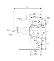
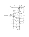
- the protruding portion 33 and the recessed portion 35 in the present embodiment are disposed on the radially outer side of the contact surfaces 34 and 36, and the combined center line CL1 of the protruding portion 33 and the recessed portion 35 is more radial than the yoke center line CL0. Located on the outside.
- the cross-sectional shape perpendicular to the axial direction of the projecting portion 33 is the base end side of the first inclined surface 33 a located outside the projecting portion 33 in the radial direction.
- the shape is located on the circumference of a circle CB having a radius RB.
- the fulcrum when the contact surfaces 34 and 36 of the adjacent iron core pieces 20A are about to open is either the first end A1 or the first end B1 of the other. Considering the case of opening the first end A1 as a fulcrum, the following condition may be satisfied to prevent the opening.
- the radial dimension (dimension between the third end portions B2 and A2) of the base end portion of the protruding portion 33 is L1
- the radial interval between the first end portion A1 and the protruding portion 33 is L2
- the first end portion B1 is L2
- the distance in the radial direction between the protrusion 33 and the protrusion 33 is L8 (L8> L2). That is, L1 + L2 + L8 is the thickness of the yoke portion 21 in the radial direction. Note that L1, L2, and L8 are arbitrary lengths.
- L2 since L2 ⁇ L8, L3a ⁇ L3b (L5a ⁇ L5b). Accordingly, as shown in FIG. 8, a circle CB having a radius RB having the first end B1 as a fulcrum has a radius radiated from a circle CB having the radius RB having the first end B1 as a fulcrum. Is long.
- the protrusion height L3b (or L5b) of the protrusion 33 that can maintain the dimension of the distance RB is the protrusion dimension of the protrusion 33. If the projecting height L3a (or L5a) is the projecting dimension, the entire first inclined surface 33b is placed inside a circle CA having a radius RA from the first end A1.
- the first inclined surface 33a enters the inside of a circle (not shown) whose radius is a line segment B1B3 ′ centered on the first end B1.
- the protrusion height L3b or L5b
- the first slope is inside the circle (not shown) whose radius is the line segment A1A3 ′ centered on the first end A1.
- All of the surface 33b enters, and all of the first inclined surface 33a enters the inside of a circle CB whose radius is the distance RB centered on the first end B1.
- first inclined surfaces 33a and 33b and the second inclined surfaces 35a and 35b, and the contact surface 34 and the contact surface are applied to bending stress with the first end A1 and the first end B1 as a fulcrum. 36 is difficult to open.
- the contact angle ⁇ is 45 °, 40 °, 30 °, 27 °, 20 °, 17 °, 15 °, 10 °, 7 ° in order from the right side of the drawing, as in FIG.
- an isosceles triangle A1A2A3 having one side L1 + L2 and an isosceles triangle B1B2B3 having one side L1 + L8 can be formed.
- the circle CA and the circle CB intersect at 7 °, 10 °, 15 °, 17 °, and 20 °.
- the isosceles triangle A1A2A3 and the isosceles triangle B1B2B3 can be configured by setting the contact angle ⁇ of the first inclined surfaces 33a and 33b within this angle range of 7 ° to 20 °.
- the position of the second end portion B ⁇ b> 3 is a reference for the protruding dimension of the protruding portion 33.
- the other configuration of the iron core piece 20A is the same as that of the iron core piece 20 described above. Moreover, although the case where the protrusion part 33 and the recessed part 35 were arrange
- the radius of the circle CB centering on the first end B1 on the radially inner side is larger than the circle CA centering on the first end A1 on the radially outer side of the contact surface 34.
- the protruding portion 33 since the protruding portion 33 has the cross-sectional shape, the shape corresponds to the circle CB having the larger radius.
- All of the surfaces 33b and 33a are concave on the inside of a circle (a circle having a line segment A1A3 ′ centered on the first end A1 and a radius RB having a radius RB centered on the first end B1). It can be set as the structure which hits the 35 2nd inclined surfaces 35b and 35a. Therefore, it can be set as the structure which is hard to produce the clearance gap between the contact surfaces 34 and 36 of 20 A of adjacent iron core pieces. As a result, the contact of the contact surfaces 34 and 36 can be maintained, and the magnetic path of the stator core 5 can be secured.
- the third embodiment is an embodiment in which the protruding portion and the recessed portion are arranged closer to the outer side in the radial direction than the yoke center line CL0, and the protruding dimension of the protruding portion is reduced as compared with the second embodiment described above.
- the core piece 20 ⁇ / b> B in the present embodiment includes a protruding portion 43 on the contact surface 44 along the radial direction of the one end portion in the circumferential direction, and the other end portion in the circumferential direction.
- the contact surface 46 along the radial direction is provided with a recess 45 that accommodates the protrusion 43 of the adjacent iron core piece 20B.
- the protrusion 43 is formed in a trapezoidal shape and has first inclined surfaces 43a and 43b on the outer side and the inner side in the radial direction.
- the first inclined surface 43a is inclined by the contact angle ⁇ c with respect to the combination center line CL1
- the first inclined surface 43b is inclined by the contact angle ⁇ with respect to the combination center line CL1.
- the combination center line CL1 in the present embodiment passes through the reference position P0 where the extension lines of the first inclined surfaces 43a and 43b (second inclined surfaces 45a and 45b) have tolerances, and is in the normal direction of the contact surfaces 44 and 46. Parallel lines.
- the recess 45 is a trapezoidal recess substantially the same shape as the protrusion 43, and has second inclined surfaces 45a and 45b on the outer side and the inner side in the radial direction.
- the second inclined surface 45a is inclined by the contact angle ⁇ c with respect to the combination center line CL1
- the second inclined surface 45b is inclined by the contact angle ⁇ with respect to the combination center line CL1.
- the concave portion 45 of the iron core piece 20B accommodates the protruding portion 43 of the adjacent iron core piece 20B in a state where the second inclined surfaces 45a and 45b are in contact with the first inclined surfaces 43a and 43b of the protruding portion 43, respectively.
- the protrusion 43 and the recess 45 in the present embodiment are disposed on the radially outer side of the contact surfaces 44 and 46, and the combined center line CL1 of the protrusion 43 and the recess 45 is more radial than the yoke center line CL0. Located on the outside.
- the cross-sectional shape perpendicular to the axial direction of the protruding portion 43 is such that the contact angle ⁇ c of the first inclined surface 43 a located outside the radial direction of the protruding portion 43 is the same.
- the shape is smaller than the contact angle ⁇ of the first inclined surface 43b located inside the protrusion 43 in the radial direction.
- the fulcrum when the contact surfaces 44 and 46 of the adjacent iron core pieces 20B are to be opened is either the first end A1 or the first end B1 of the other.
- L3a and L5a calculated from the isosceles triangle A1A2A3 are the same as those in FIG.
- the dimensions L1 and L8 are the same as in FIG. 7, and the contact angle is ⁇ c ⁇ .
- the protrusion dimension L3c (L5c) of the protrusion 43 is L3c ⁇ L3b (L5c ⁇ L5b) as compared with the protrusion dimension L3b (L5b) of the protrusion 33 of FIG. That is, the protrusion dimension of the protrusion part 43 can be made smaller than the case of the protrusion part 33 of FIG. In this manner, the position of the tip of the protrusion 43 can be adjusted by changing the contact angle ⁇ c of the first inclined surface 43a. Therefore, for example, ⁇ c may be set so that the protruding dimension L3c (L5c) is equal to the protruding dimension L3a (L5a).
- L7c L1 / (tan ⁇ + tan ⁇ c) It becomes.
- the second end B3 is located on the tip side from the contact surfaces 44 and 46 with respect to the second end A3. This shows the state of FIG.
- a configuration like the iron core piece 20 ⁇ / b> B in FIG. 10 may be used.
- the protrusion dimension L3c (L5c) can be made substantially equal to the protrusion dimension L3a (L5a) by setting the contact angle ⁇ c to about 10 °.
- the other configuration of the iron core piece 20B is the same as that of the iron core piece 20A described above.
- the projecting dimension of the projecting part 43 from the contact surfaces 44 and 46 is within a predetermined dimension due to the structural convenience of the iron core piece 20B (for example, the ratio with the dimension of the yoke part 21 in the radial direction of the iron core piece 20B). You may want to limit to
- the projecting portion 43 since the projecting portion 43 has the above-described cross-sectional shape, a bending force with the radially outer first end A1 acting as a fulcrum acts, and the radially inner first end B1.
- all of the first inclined surfaces 43b and 43a are circles (a circle CA having a radius RA from the first end A1 and a center at the first end B1). It is possible to adopt a structure that hits the second inclined surfaces 45b and 45a of the recess 45 inside the circle CB) having a radius of the distance RB. Therefore, it can be set as the structure where a clearance gap hardly arises between the contact surfaces 44 and 46 of adjacent iron core piece 20B.
- the contact of the contact surfaces 44 and 46 can be maintained, and the magnetic path of the stator core 5 can be secured.
- the position (protrusion dimension) of the tip of the protrusion 43 can be adjusted by adjusting the contact angle ⁇ c, the protrusion dimension of the protrusion 43 from the contact surfaces 44 and 46 can be reduced. . Therefore, the above needs can be met.
- the iron core piece 120 in the present modification includes a protruding portion 123 on the contact surface 124 along the radial direction of the one side end portion in the circumferential direction, and extends in the radial direction of the other side end portion in the circumferential direction.
- the recessed part 125 which accommodates the protrusion part 123 of the adjacent iron core piece 120 is provided.
- the protrusion 123 and the recess 125 are provided at the center position in the radial direction of the yoke 121. That is, the combination center line CL1 and the yoke center line CL0 substantially coincide.
- the projecting portion 123 is formed in a substantially isosceles triangle shape, and has first inclined surfaces 123a and 123b on the outer side and the inner side in the radial direction.
- the first inclined surfaces 123a and 123b are inclined by a contact angle ⁇ with respect to the combination center line CL1.
- the recess 125 is an isosceles triangular recess that is substantially the same shape as the protrusion 123, and includes second inclined surfaces 125a and 125b on the outer side and the inner side in the radial direction.
- the second inclined surfaces 125a and 125b are inclined by the contact angle ⁇ with respect to the combination center line CL1, respectively.
- the concave portion 125 of the iron core piece 120 accommodates the protruding portion 123 of the adjacent iron core piece 120 in a state where the second inclined surfaces 125a and 125b are in contact with the first inclined surfaces 123a and 123b of the protruding portion 123, respectively.
- the cross-sectional shape perpendicular to the axial direction of the protruding portion 123 is set as follows. That is, as shown in FIGS. 12 and 13, the protruding portion 123 is centered on the first outer end A ⁇ b> 1 in the radial direction of the contact surface 124, and is located on the opposite side of the first end A ⁇ b> 1 of the protruding portion 123.
- the first inclined surface 123b is in contact with the second inclined surface 125b on the inner side of a circle CA whose radius is the distance RA between the first inclined surface 123b and the second end portion A3 on the distal end side.
- the protrusion 123 is centered on the inner first end B1 in the radial direction of the contact surface 124, and is on the tip side of the first inclined surface 123a located on the opposite side of the protrusion 123 from the first end B1.
- the first inclined surface 123a has a shape in contact with the second inclined surface 125a inside a circle CB having a radius RB between the second end B3 and the first end B1.
- the third end portion A2 on the proximal end side of the first inclined surface 123b of the protruding portion 123 is located on the circumference of the circle CA. Further, the third end B2 on the base end side of the first inclined surface 123a of the protruding portion 123 is located on the circumference of the circle CB.
- the protrusion 123 has the above-described cross-sectional shape, so that the protrusion 123 and the recess 125 are connected to each other even when a bending force with the first end A1 or the first end B1 as a fulcrum acts. It is possible to make a structure in which a gap is unlikely to be generated between the contact surfaces 124 and 126 of the iron core piece 120.
- the protruding portion 123 and the recessed portion 125 may be disposed closer to the radially outer side or the inner side than the yoke center line CL0.
- the gap ⁇ L (the same applies to ⁇ L shown in FIG. 4 and the like) is the size of the interference when the frame 4 is shrink-fitted to the annularly connected iron core pieces 20C, and the perfect circle of the inner diameter of the frame 4 It is preferable to set an appropriate value depending on the tip shape of the tooth portion 22 and the like.
- the contact angle ⁇ is set so as to form the isosceles triangle A1A2A3 and the isosceles triangle B1B2B3 has been described above, the shapes of the protrusions and the recesses are not limited thereto. Even when such an isosceles triangle is not formed, at least a part of the first inclined surface 23b has a cross-sectional shape of the projecting portion 23 inside the circle CA having the first end A1 as a center and a distance RA as a radius.
- the cross-sectional shape of the protruding portion 23 is such that at least a part of the first inclined surface 23a is in contact with the second inclined surface 25a inside the circle CB having the first end B1 as the center and the distance RB as the radius. If it exists, it can be set as the structure where a clearance gap is hard to produce between the contact surfaces 24 and 26 of the adjacent iron core piece 20 with respect to the bending force which makes 1st edge part B1 a fulcrum.
- the fourth embodiment is an embodiment in which a contact area between each core piece is increased by providing a plurality of protrusions and recesses on each core piece.
- 5-1. Schematic structure of iron core piece An example of a schematic configuration of the iron core piece 220 of the present embodiment will be described with reference to FIG.
- FIG. 15 is an explanatory view showing a part of the stator core 5 extracted.
- illustration of the bobbin 6 and the resin part 8 is abbreviate
- the iron core piece 220 includes an arc-shaped yoke portion 221 and a teeth portion 222.
- the teeth part 222 has a main body part 222a and a widened part 222b.
- Each iron core piece 220 has contact surfaces 224 and 226 along the radial direction in contact with the adjacent iron core pieces 220 at both ends in the circumferential direction.
- Two protrusions 223 are provided on the contact surface 224 on one end (left side in FIG. 15) in the circumferential direction, and on the contact surface 226 on the other end (right side in FIG. 15) in the circumferential direction.
- Two recesses 225 are provided.
- the core pieces 220 adjacent to each other in the circumferential direction are connected in a state where the two protruding portions 223 of the core pieces 220 adjacent to the two recesses 225 are accommodated and the contact surfaces 224 and 226 are in contact with each other.
- the two protrusions 223 have the same shape and the same size, and are arranged symmetrically in the radial direction about the yoke center line CL0.
- the two recesses 225 have the same shape and the same size, respectively, and are symmetrically arranged in the radial direction around the yoke center line CL0.
- the protrusions 223 and the recesses 225 located on the radially outer side are referred to as “outer protrusions 223” and “outer recesses 225”, and the protrusions 223 and the recesses 225 located on the radially inner side are referred to as “inner protrusions”.
- Part 223 "and" inner recess 225 ".
- the radial dimensions (dimensions between the third end portions B2 and A2) of the base end portions of the outer protruding portion 223 and the inner protruding portion 223 are L1, the first end portions A1 and B1, and the protruding portions 223, respectively.
- L2 in the radial direction (the distance between the first end A1 and the third end B2 of the outer protrusion 223, the distance between the first end B1 and the third end A2 of the inner protrusion 223) is L2.
- the radial distance between the outer protrusion 223 and the inner protrusion 223 is L8. That is, 2 (L1 + L2) + L8 is the thickness of the yoke portion 221 in the radial direction.
- L1 and L2 are arbitrary lengths.
- the outer protruding portion 223 and the inner protruding portion 223 have the same shape and the same size, and are arranged radially symmetrically about the yoke center line CL0. However, they have different shapes and different sizes, and the yoke center line CL0. You may arrange
- This protrusion dimension L3 is the basis of the height of the outer protrusion 223. In fact, since the corner of the outer protrusion 223 is rounded by a press die, the actual height of the outer protrusion 223 is added to the radius R of the corner. Dimensions.
- the coefficient ⁇ takes into account the dimensional variation due to the lamination of the steel sheets of the iron core piece 220, and it is preferable that the radius R is added several percent to about 30% (for example, ⁇ ⁇ 1.3).
- the cross-sectional shape of the inner protrusion 223 will be described.
- the inner protrusion 223 and the outer protrusion 223 have the same shape and the same size. For this reason, when considering the isosceles triangle B1B2B3 whose one side is L1 + L2 with the first end B1 as a vertex, the dimensional relationship of the inner protrusion 223 is the same as that of the upper protrusion 223. That is, as shown in FIG.
- the isosceles triangle A1A2A3 and the isosceles triangle B1B2B3 are configured so that the combination of the outer protrusion 223 and the outer recess 225 and the combination of the inner protrusion 223 and the inner recess 225 does not come off due to bending stress.
- the contact angle ⁇ is preferably set.
- FIG. 6 shows a circle CB having a radius RB with the first end B1 as a fulcrum.
- the contact angle ⁇ intersecting with the circle CB is 7 °, 10 °, 15 °, 17 °, and 20 °, and the contact angle ⁇ of the first inclined surface 223a is within this angle range 7.
- an isosceles triangle B1B2B3 can be formed.
- FIG. 6 shows a case where the intersection with the circle CB when the contact angle ⁇ is set to 15 ° is set at the second end B3, for example.
- the isosceles triangle A1A2A3 can be configured by setting the contact angle ⁇ of the first inclined surface 223b within this angle range of 7 ° to 20 °.
- the contact angle ⁇ is set in the range of 9.5 ° to 17.2 ° corresponding to the friction coefficient of the laminated silicon steel sheet, so that an annular shape is obtained.
- each of the core pieces 220 can be provided with two protrusions 223 and two recesses 225 to increase the contact area, so that the magnetic path of the stator core 5 can be expanded.
- the configuration of the present embodiment is effective for a small-sized (small capacity) rotating electrical machine.
- the yoke of the stator core 5 is provided.
- the portion 221 preferably has a certain thickness, and is particularly suitable for a middle-sized to large-sized (medium capacity to large capacity) rotating electrical machine.
- each of the core pieces 220 is provided with two protrusions 223 and two recesses 225, but may be provided with three or more. In that case, the magnetic path expansion effect can be further enhanced.
- a minute gap (for example, about several tens of ⁇ m) is provided between the contact surface 224 and the contact surface 226 of the adjacent iron core pieces 220.
- the front ends of the two protrusions 223 and the bottoms of the two recesses 225 are in contact with each other.
- the gap ⁇ L depends on the size of the interference when the frame 4 is shrink-fitted onto the annularly connected iron core pieces 220, the roundness of the inner diameter of the frame 4, the tip shape of the tooth portion 222, and the like. It is preferable to set to an appropriate value.
- each core piece 220 has one tooth portion 222 has been described as an example. However, for example, when each winding piece is distributedly wound, each core piece 220 may have two or more teeth portions 222. Good. By applying the connection shape described above to such an iron core piece, the same effects as those of the embodiments can be obtained.
Landscapes
- Engineering & Computer Science (AREA)
- Power Engineering (AREA)
- Iron Core Of Rotating Electric Machines (AREA)
Abstract
Description
第1実施形態の回転電機について説明する。
図1及び図2を用いて、本実施形態に係る回転電機1の全体構成の一例について説明する。図1は回転電機1の全体構成の一例を表す軸方向断面図、図2は回転電機1の全体構成の一例を表す図1のII-II断面における横断面図である。
次に、図3を用いて、鉄心片20の概略構成の一例について説明する。図3は固定子鉄心5の一部分を抽出して表す説明図である。なお、図3ではボビン6や樹脂部8の図示を省略している。
次に、図4及び図5を用いて、鉄心片20の突出部23及び凹部25の形状の一例について説明する。図4は鉄心片20の突出部23及び凹部25の軸方向に垂直な断面形状の一例を表す説明図である。図5は曲げ応力が作用したときに突出部の第1傾斜面が凹部の第2傾斜面に当たることを表す説明図である。
L4=2(L1+L2)sinθ
となる。
L3=L4cosθ=2(L1+L2)sinθcosθ
=(L1+L2)sin2θ
となる。
L5=L3+αR=(L1+L2)sin2θ+αR
となる。
L6=L5+ΔL
となる。
L7=(L1/2)/tanθ
である。
次に、図6を用いて、接触角度θの設定条件の一例について説明する。前述のように、突出部23と凹部25の組み合わせが曲げ応力によって外れないためには、二等辺三角形A1A2A3と二等辺三角形B1B2B3が構成されるように、接触角度θが設定されるのが好ましい。
前述のように、鉄心片20は、例えばプレス抜き加工により所定の形状に形成された鋼板を積層して構成されている。接触角度θは、上記鋼板の摩擦係数に基づいて設定されるのがより好ましい。
摩擦係数μ=tanθo
と表わされる。この式に、摩擦係数μの実測値0.167~0.308を代入すると、
μ=0.167~0.308=tan9.5°~tan17.2°
となることから、最大摩擦角度θo=9.5°~17.2°となる。すなわち、第1傾斜面23a,23b及び第2傾斜面25a,25bの接触角度θが9.5°~17.2°の範囲の場合に、第1傾斜面23a,23bと第2傾斜面25a,25bとの間で最大摩擦力が得られることとなる。
本実施形態の回転電機1は、概略次のようにして組み立てられる。各鉄心片20は、ティース部22にボビン6及び巻線7が装着された後、環状に連結されて固定子鉄心5が形成される。そして、当該固定子鉄心5の外側にフレーム4が圧入又は焼きばめ等により固定される。その後、固定子鉄心5と固定子鉄心5に装着された複数の巻線7等とが樹脂部8で一体化される。このようにして、固定子2が組み立てられる。
以上説明した本実施形態の回転電機1によれば、次の効果を奏する。すなわち、複数の鉄心片20が円環状に連結されて構成された固定子鉄心5がフレーム4の内側に焼きばめ等により固定された回転電機1では、フレーム4の内径や肉厚のばらつき、鉄心片20の外径のばらつき等に起因して、鉄心片20の外周面や接触面に不均等な圧縮力が作用する場合がある。この圧縮力の強弱により、固定子鉄心5の円環形状に折れ曲がりが生じて鉄心片20の接触面24,26間に隙間が生じた場合には、固定子鉄心5を通る磁束の妨げとなる。
次に、第2実施形態について説明する。第2実施形態は、突出部及び凹部をヨーク中心線CL0よりも径方向外側寄りに配置した実施形態である。
図7及び図8を用いて、本実施形態の鉄心片20Aの突出部33及び凹部35の形状の一例について説明する。図7及び図8に示すように、本実施形態における鉄心片20Aは、周方向における一方側端部の径方向に沿った接触面34に突出部33を備え、周方向における他方側端部の径方向に沿った接触面36に、隣接した鉄心片20Aの突出部33を収容する凹部35を備える。
L4a=2(L1+L2)sinθ
L3a=L4a×cosθ=2(L1+L2)sinθcosθ
=(L1+L2)sin2θ
L5a=L3a+αR=(L1+L2)sin2θ+αR
となる。
L4b=2(L1+L8)sinθ
L3b=(L1+L8)sin2θ
L5b=(L1+L8)sin2θ+αR
となる。
である。
次に、図9を用いて、接触角度θの設定条件の一例について説明する。図9に示す例では、前述の図6と同様に、接触角度θが図の右側から順に45°,40°,30°,27°,20°,17°,15°、10°,7°となる線が、第3端部B2,A2のそれぞれから引かれている。これらの接触角度の線に対し、第1端部A1を支点とした半径RA(=L1+L2)の円CAと、第1端部B1を支点とした半径RB(=L1+L8)の円CBが交わるならば、1辺がL1+L2の二等辺三角形A1A2A3、1辺がL1+L8の二等辺三角形B1B2B3を構成することができる。図9に示す例では、円CA及び円CBともに、7°,10°,15°,17°,20°で交差している。つまり、第1傾斜面33a,33bの接触角度θをこの角度範囲7°~20°に設定することで、二等辺三角形A1A2A3及び二等辺三角形B1B2B3を構成することができる。なお、図9では、例えば接触角度θを15°に設定した場合の、円CAとの交点が第2端部A3、円CBとの交点が第2端部B3として示されている。本実施形態では、上述のように、第2端部B3位置が突出部33の突出寸法の基準となる。
以上説明した第2実施形態によれば、次の効果を奏する。すなわち、一般に、鉄心片20Aのヨーク部21を通る磁束の密度は、径方向内側の方が径方向外側よりも高い。したがって、突出部33及び凹部35を接触面34,36における径方向の外側寄りに配置することで、磁路を拡大でき、鉄損の低減効果を高めることができる。
次に、第3実施形態について説明する。第3実施形態は、突出部及び凹部をヨーク中心線CL0よりも径方向外側寄りに配置しつつ、上述の第2実施形態よりも突出部の突出寸法を低減させた実施形態である。
図10及び図11を用いて、本実施形態の鉄心片20Bの突出部43及び凹部45の形状の一例について説明する。図10及び図11に示すように、本実施形態における鉄心片20Bは、周方向における一方側端部の径方向に沿った接触面44に突出部43を備え、周方向における他方側端部の径方向に沿った接触面46に、隣接した鉄心片20Bの突出部43を収容する凹部45を備える。
L4c=2(L1+L8)sinθc
L3c=L4c×cosθ=2(L1+L8)sinθc×cosθc
=(L1+L8)sin2θc
L5c=(L1+L8)sin2θc+αR
となる。
L7c=L1/(tanθ+tanθc)
となる。この場合の距離L7cは、図7の場合のL7=(L1/2)/tanθより大きくなる。
次に、前述の図9を用いて、接触角度θの設定条件の一例について説明する。先の図9に示すように、第2端部B3は、接触面44,46から第2端部A3よりも先端側に位置している。これは、図7の状態を示している。図7の突出部33よりも突出寸法を小さくしたい場合、図10の鉄心片20Bのような構成とすればよい。上記図9に示す例では、接触角度15°の線と円CAとの交点である第2端部A3とほぼ同じ突出位置で円CBと交わるのは接触角度10°の線である。したがって、接触角度θcを約10°前後に設定することにより、突出寸法L3c(L5c)を突出寸法L3a(L5a)と略等しくすることができる。
以上説明した第3実施形態によれば、次の効果を奏する。すなわち、突出部43の接触面44,46からの突出寸法は、鉄心片20Bの構造上の都合(例えば鉄心片20Bのヨーク部21の径方向の寸法との割合等)により、所定の寸法以内に制限したい場合がある。
なお、開示の実施形態は、上記に限られるものではなく、その趣旨及び技術的思想を逸脱しない範囲内で種々の変形が可能である。以下、そのような変形例を説明する。
以上では、突出部及び凹部が略台形状である場合を一例として説明したが、突出部及び凹部の形状を略三角形状としてもよい。図12及び図13を用いて、本変形例における鉄心片の突出部及び凹部の形状の一例について説明する。
以上では、隣接する鉄心片20の接触面24と接触面26とが接触する場合を一例として説明したが、接触面に作用する圧縮力を緩和するために、接触面24と接触面26との間に微小な隙間を設ける構成としてもよい。図14を用いて、本変形例における鉄心片の突出部及び凹部の形状の一例について説明する。
L6=L5-ΔL
となる。
以上では、二等辺三角形A1A2A3や二等辺三角形B1B2B3が構成されるように接触角度θが設定される場合について説明したが、突出部及び凹部の形状はこれに限定されるものではない。そのような二等辺三角形が構成されない場合でも、突出部23の断面形状が、第1端部A1を中心とし距離RAを半径とする円CAの内側において、第1傾斜面23bの少なくとも一部が第2傾斜面25bと接触する形状であれば、第1端部A1を支点とする曲げ力に対して隣接する鉄心片20の接触面24,26間に隙間が生じにくい構造とすることができる。また、突出部23の断面形状が、第1端部B1を中心とし距離RBを半径とする円CBの内側において、第1傾斜面23aの少なくとも一部が第2傾斜面25aと接触する形状であれば、第1端部B1を支点とする曲げ力に対して隣接する鉄心片20の接触面24,26間に隙間が生じにくい構造とすることができる。
次に、第4実施形態について説明する。第4実施形態は、各鉄心片に突出部及び凹部を複数設けることにより、各鉄心片間の接触面積を増大させた実施形態である。
(5-1.鉄心片の概略構成)
図15を用いて、本実施形態の鉄心片220の概略構成の一例について説明する。図15は固定子鉄心5の一部分を抽出して表す説明図である。なお、図15ではボビン6や樹脂部8の図示を省略している。
次に、図16及び図17を用いて、鉄心片220の突出部223及び凹部225の形状の一例について説明する。
L4=2(L1+L2)sinθ
となる。
L3=L4cosθ=2(L1+L2)sinθcosθ
=(L1+L2)sin2θ
となる。
L5=L3+αR=(L1+L2)sin2θ+αR
となる。
L6=L5+ΔL
となる。
L7=(L1/2)/tanθ
である。
次に、前述の図6を用いて、接触角度θの設定条件の一例について説明する。前述のように、外側突出部223と外側凹部225及び内側突出部223と内側凹部225の組み合わせが曲げ応力によって外れないためには、二等辺三角形A1A2A3と二等辺三角形B1B2B3が構成されるように、接触角度θが設定されるのが好ましい。
以上説明した第4実施形態によれば、次の効果を奏する。すなわち、回転電機の小型化が進み、固定子鉄心5のヨーク部221が薄くなると、隣接する鉄心片220同士の接触面積が減少するので、磁路の減少を招く可能性がある。本実施形態によれば、各鉄心片220に2つの突出部223及び2つの凹部225をそれぞれ設けて接触面積を増大することができるので、固定子鉄心5の磁路を拡大できる。その上で、第1端部A1,B1を支点とする曲げ力が作用した場合でも、隣接する鉄心片220の接触面224,226間の隙間を生じにくい構造とすることができる。以上のように、本実施形態の構成は、小型(小容量)の回転電機に有効であるが、径方向に2つの突出部223及び2つの凹部225を設ける構造上、固定子鉄心5のヨーク部221にある程度の厚みがある場合が好ましく、中型から大型(中容量から大容量)の回転電機に対して特に好適である。
なお、開示の実施形態は、上記に限られるものではなく、その趣旨及び技術的思想を逸脱しない範囲内で種々の変形が可能である。以下、そのような変形例を説明する。
以上では、隣接する鉄心片220の接触面224と接触面226とが接触する場合を一例として説明したが、接触面に作用する圧縮力を緩和するために、接触面224と接触面226との間に微小な隙間を設ける構成としてもよい。図18を用いて、本変形例における鉄心片の突出部及び凹部の形状の一例について説明する。
L6=L5-ΔL
となる。
以上では、各鉄心片220が1つのティース部222を有する場合を一例として説明したが、例えば巻線を分布巻きする場合等、各鉄心片220が2つ以上のティース部222を有する構成としてもよい。このような鉄心片に対しても以上説明した接続形状を適用することで、各実施形態等と同様の効果を得ることができる。
4 フレーム
5 固定子鉄心
20 鉄心片
20A 鉄心片
20B 鉄心片
20C 鉄心片
23 突出部
23a,23b 第1傾斜面
24 接触面
25 凹部
25a,25b 第2傾斜面
26 接触面
33 突出部
33a,33b 第1傾斜面
34 接触面
35 凹部
35a,35b 第2傾斜面
36 接触面
43 突出部
43a,43b 第1傾斜面
44 接触面
45 凹部
45a,45b 第2傾斜面
46 接触面
120 鉄心片
123 突出部
123a,123b 第1傾斜面
124 接触面
125 凹部
125a,125b 第2傾斜面
126 接触面
220 鉄心片
223 突出部
223a,223b 第1傾斜面
224 接触面
225 凹部
225a,225b 第2傾斜面
226 接触面
A1,B1 第1端部
AX 回転軸心
A2,B2 第3端部
A3,B3 第2端部
CA,CB 円
RA,RB 距離
μ 摩擦係数
θ 接触角度(傾斜角度)
θc 接触角度(傾斜角度)
Claims (8)
- 回転軸心周りの周方向における一方側端部及び他方側端部に、前記回転軸心に対する径方向に沿った接触面を備え、固定子鉄心を構成する複数の鉄心片と、
前記一方側端部の前記接触面に設けられ、前記径方向の外側及び内側に第1傾斜面を備えた先細り形状の突出部と、
前記他方側端部の前記接触面に設けられ、前記径方向の外側及び内側に前記第1傾斜面と接触する第2傾斜面を備え、隣接する前記鉄心片の前記突出部を収容する凹部と、を有し、
前記突出部の前記回転軸心に垂直な断面形状は、
前記接触面の前記径方向における一方側の第1端部を中心とし、前記突出部の前記第1端部とは反対側に位置する前記第1傾斜面の先端側の第2端部と前記第1端部との距離を半径とする円の内側において、前記第1端部とは反対側に位置する前記第1傾斜面の少なくとも一部が前記第2傾斜面と接触する形状である
ことを特徴とする回転電機。 - 前記突出部の前記断面形状は、
前記突出部の前記第1端部とは反対側に位置する前記第1傾斜面の基端側の第3端部が、前記円の円周上に位置する形状である
ことを特徴とする請求項1に記載の回転電機。 - 前記突出部及び前記凹部は、
前記接触面における前記径方向の外側寄りに配置されており、
前記突出部の前記断面形状は、
前記突出部の前記径方向の外側に位置する前記第1傾斜面の基端側の前記第3端部が、前記接触面の前記径方向における内側の前記第1端部を中心とし、前記突出部の前記径方向の外側に位置する前記第1傾斜面の先端側の前記第2端部と前記第1端部との距離を半径とする前記円の円周上に位置する形状である
ことを特徴とする請求項2に記載の回転電機。 - 前記突出部及び前記凹部は、
前記接触面における前記径方向の外側寄りに配置されており、
前記突出部の前記断面形状は、
前記突出部の前記径方向の外側に位置する前記第1傾斜面の前記接触面の法線方向に対する傾斜角度が、前記突出部の前記径方向の内側に位置する前記第1傾斜面の前記法線方向に対する傾斜角度よりも小さい形状である
ことを特徴とする請求項2又は3に記載の回転電機。 - 前記鉄心片は、
複数の鋼板が積層されて構成されており、
前記突出部の前記断面形状は、
前記接触面の法線方向に対する前記第1傾斜面の傾斜角度が、前記鋼板の摩擦係数に基づいて設定された形状である
ことを特徴とする請求項1乃至4のいずれか1項に記載の回転電機。 - 回転軸心周りの周方向における一方側端部及び他方側端部に、前記回転軸心に対する径方向に沿った接触面を備え、固定子鉄心を構成する複数の鉄心片と、
前記一方側端部の前記接触面に設けられ、前記径方向の外側及び内側に第1傾斜面を備えた先細り形状の突出部と、
前記他方側端部の前記接触面に設けられ、前記径方向の外側及び内側に前記第1傾斜面と接触する第2傾斜面を備え、隣接する前記鉄心片の前記突出部を収容する凹部と、を有し、
前記突出部の前記回転軸心に垂直な断面形状は、
前記突出部の基端部の前記径方向の寸法をL1、前記接触面の前記径方向における一方側の第1端部と前記突出部との前記径方向の間隔をL2、前記接触面の法線方向における前記突出部の前記接触面からの突出寸法をL3、前記突出部の前記第1端部とは反対側に位置する前記第1傾斜面の前記法線方向に対する傾斜角度をθとした場合に、
L3=(L1+L2)sin2θ
を満たす形状である
ことを特徴とする回転電機。 - 前記一方側端部の前記接触面に、2以上の前記突出部が設けられ、
前記他方側端部の前記接触面に、隣接する前記鉄心片の前記2以上の突出部をそれぞれ収容する2以上の前記凹部が設けられている
ことを特徴とする請求項1乃至6のいずれか1項に記載の回転電機。 - 請求項1乃至7のいずれか1項に記載の回転電機の製造方法であって、
複数の鉄心片を環状に連結して固定子鉄心を形成することと、
前記固定子鉄心の外側にフレームを焼きばめにより固定することと、
を有することを特徴とする回転電機の製造方法。
Priority Applications (4)
| Application Number | Priority Date | Filing Date | Title |
|---|---|---|---|
| JP2018506018A JP6771745B2 (ja) | 2016-03-18 | 2017-03-16 | 回転電機及び回転電機の製造方法 |
| EP17766806.8A EP3432447B1 (en) | 2016-03-18 | 2017-03-16 | Dynamo-electric machine and method for manufacturing dynamo-electric machine |
| CN201780017912.1A CN109075627B (zh) | 2016-03-18 | 2017-03-16 | 旋转电机和旋转电机的制造方法 |
| US16/131,037 US10855123B2 (en) | 2016-03-18 | 2018-09-14 | Rotating electrical machine and producing method of rotating electrical machine |
Applications Claiming Priority (2)
| Application Number | Priority Date | Filing Date | Title |
|---|---|---|---|
| PCT/JP2016/058849 WO2017158847A1 (ja) | 2016-03-18 | 2016-03-18 | 回転電機及び回転電機の製造方法 |
| JPPCT/JP2016/058849 | 2016-03-18 |
Related Child Applications (1)
| Application Number | Title | Priority Date | Filing Date |
|---|---|---|---|
| US16/131,037 Continuation US10855123B2 (en) | 2016-03-18 | 2018-09-14 | Rotating electrical machine and producing method of rotating electrical machine |
Publications (1)
| Publication Number | Publication Date |
|---|---|
| WO2017159811A1 true WO2017159811A1 (ja) | 2017-09-21 |
Family
ID=59850468
Family Applications (2)
| Application Number | Title | Priority Date | Filing Date |
|---|---|---|---|
| PCT/JP2016/058849 Ceased WO2017158847A1 (ja) | 2016-03-18 | 2016-03-18 | 回転電機及び回転電機の製造方法 |
| PCT/JP2017/010748 Ceased WO2017159811A1 (ja) | 2016-03-18 | 2017-03-16 | 回転電機及び回転電機の製造方法 |
Family Applications Before (1)
| Application Number | Title | Priority Date | Filing Date |
|---|---|---|---|
| PCT/JP2016/058849 Ceased WO2017158847A1 (ja) | 2016-03-18 | 2016-03-18 | 回転電機及び回転電機の製造方法 |
Country Status (5)
| Country | Link |
|---|---|
| US (1) | US10855123B2 (ja) |
| EP (1) | EP3432447B1 (ja) |
| JP (1) | JP6771745B2 (ja) |
| CN (1) | CN109075627B (ja) |
| WO (2) | WO2017158847A1 (ja) |
Cited By (1)
| Publication number | Priority date | Publication date | Assignee | Title |
|---|---|---|---|---|
| JP2019176665A (ja) * | 2018-03-29 | 2019-10-10 | 日本製鉄株式会社 | 分割型固定子および回転電機 |
Families Citing this family (4)
| Publication number | Priority date | Publication date | Assignee | Title |
|---|---|---|---|---|
| EP3614529A1 (de) * | 2018-08-23 | 2020-02-26 | Siemens Aktiengesellschaft | Einzelzahnsegment |
| JP6676133B1 (ja) * | 2018-11-26 | 2020-04-08 | 山洋電気株式会社 | 電機子モールド構造 |
| DE102019107136A1 (de) * | 2019-03-20 | 2020-09-24 | Gkn Sinter Metals Engineering Gmbh | Klauenpol-Stator für eine Transversalflussmaschine |
| DE102022103713A1 (de) | 2022-02-17 | 2023-08-17 | Voith Patent Gmbh | Polbaugruppe zum Aufbau eines Polrings für eine elektrische Maschine |
Citations (8)
| Publication number | Priority date | Publication date | Assignee | Title |
|---|---|---|---|---|
| JPH11289695A (ja) * | 1998-03-31 | 1999-10-19 | Toshiba Corp | 電動機鉄心 |
| JPH11341716A (ja) * | 1998-05-29 | 1999-12-10 | Nippon Seiko Kk | 分割磁極型電動モータ |
| JP2001045684A (ja) * | 1999-07-30 | 2001-02-16 | Hitachi Ltd | 電動機固定子鉄心の製造方法 |
| JP3430521B2 (ja) | 1992-09-24 | 2003-07-28 | 松下電器産業株式会社 | 回転電機の固定子 |
| WO2006120975A1 (ja) * | 2005-05-06 | 2006-11-16 | Mitsuba Corporation | 電動機、回転電機及びそのステータ、並びにこのステータの製造方法 |
| WO2008047942A1 (en) * | 2006-10-20 | 2008-04-24 | Toyota Jidosha Kabushiki Kaisha | Stator core and rotating electrical machine |
| JP2011135634A (ja) * | 2009-12-22 | 2011-07-07 | Toyota Motor Corp | ステータおよびこのステータを備えるモータ |
| JP2014180090A (ja) * | 2013-03-14 | 2014-09-25 | Mitsubishi Electric Corp | 回転電機の固定子、回転電機の固定子の製造方法及び回転電機 |
Family Cites Families (10)
| Publication number | Priority date | Publication date | Assignee | Title |
|---|---|---|---|---|
| US6744166B2 (en) * | 2001-01-04 | 2004-06-01 | Emerson Electric Co. | End cap assembly for a switched reluctance electric machine |
| US7012350B2 (en) | 2001-01-04 | 2006-03-14 | Emerson Electric Co. | Segmented stator switched reluctance machine |
| US20020093269A1 (en) | 2001-01-16 | 2002-07-18 | Harter Bernard G. | Slot area undercut for segmented stators |
| US6897591B2 (en) | 2001-03-26 | 2005-05-24 | Emerson Electric Co. | Sensorless switched reluctance electric machine with segmented stator |
| US6700284B2 (en) | 2001-03-26 | 2004-03-02 | Emerson Electric Co. | Fan assembly including a segmented stator switched reluctance fan motor |
| US20020139606A1 (en) * | 2001-04-03 | 2002-10-03 | Williams Donald J. | Electric power steering system including a segmented stator switched reluctance motor |
| US6584813B2 (en) | 2001-03-26 | 2003-07-01 | Emerson Electric Co. | Washing machine including a segmented stator switched reluctance motor |
| US7659570B2 (en) | 2005-05-09 | 2010-02-09 | Alpha & Omega Semiconductor Ltd. | Power MOSFET device structure for high frequency applications |
| DE102010028509A1 (de) * | 2009-12-30 | 2011-07-07 | Robert Bosch GmbH, 70469 | Stator in einem Elektromotor |
| DE102010007885A1 (de) * | 2010-02-13 | 2011-08-18 | Daimler AG, 70327 | Stator einer elektrischen Maschine |
-
2016
- 2016-03-18 WO PCT/JP2016/058849 patent/WO2017158847A1/ja not_active Ceased
-
2017
- 2017-03-16 CN CN201780017912.1A patent/CN109075627B/zh active Active
- 2017-03-16 JP JP2018506018A patent/JP6771745B2/ja active Active
- 2017-03-16 EP EP17766806.8A patent/EP3432447B1/en active Active
- 2017-03-16 WO PCT/JP2017/010748 patent/WO2017159811A1/ja not_active Ceased
-
2018
- 2018-09-14 US US16/131,037 patent/US10855123B2/en active Active
Patent Citations (8)
| Publication number | Priority date | Publication date | Assignee | Title |
|---|---|---|---|---|
| JP3430521B2 (ja) | 1992-09-24 | 2003-07-28 | 松下電器産業株式会社 | 回転電機の固定子 |
| JPH11289695A (ja) * | 1998-03-31 | 1999-10-19 | Toshiba Corp | 電動機鉄心 |
| JPH11341716A (ja) * | 1998-05-29 | 1999-12-10 | Nippon Seiko Kk | 分割磁極型電動モータ |
| JP2001045684A (ja) * | 1999-07-30 | 2001-02-16 | Hitachi Ltd | 電動機固定子鉄心の製造方法 |
| WO2006120975A1 (ja) * | 2005-05-06 | 2006-11-16 | Mitsuba Corporation | 電動機、回転電機及びそのステータ、並びにこのステータの製造方法 |
| WO2008047942A1 (en) * | 2006-10-20 | 2008-04-24 | Toyota Jidosha Kabushiki Kaisha | Stator core and rotating electrical machine |
| JP2011135634A (ja) * | 2009-12-22 | 2011-07-07 | Toyota Motor Corp | ステータおよびこのステータを備えるモータ |
| JP2014180090A (ja) * | 2013-03-14 | 2014-09-25 | Mitsubishi Electric Corp | 回転電機の固定子、回転電機の固定子の製造方法及び回転電機 |
Non-Patent Citations (1)
| Title |
|---|
| See also references of EP3432447A4 |
Cited By (2)
| Publication number | Priority date | Publication date | Assignee | Title |
|---|---|---|---|---|
| JP2019176665A (ja) * | 2018-03-29 | 2019-10-10 | 日本製鉄株式会社 | 分割型固定子および回転電機 |
| JP7047533B2 (ja) | 2018-03-29 | 2022-04-05 | 日本製鉄株式会社 | 分割型固定子および回転電機 |
Also Published As
| Publication number | Publication date |
|---|---|
| JP6771745B2 (ja) | 2020-10-21 |
| US10855123B2 (en) | 2020-12-01 |
| CN109075627A (zh) | 2018-12-21 |
| EP3432447A1 (en) | 2019-01-23 |
| WO2017158847A1 (ja) | 2017-09-21 |
| EP3432447B1 (en) | 2021-05-05 |
| JPWO2017159811A1 (ja) | 2019-01-10 |
| US20190013706A1 (en) | 2019-01-10 |
| EP3432447A4 (en) | 2019-11-13 |
| CN109075627B (zh) | 2020-10-02 |
Similar Documents
| Publication | Publication Date | Title |
|---|---|---|
| CN104702003B (zh) | 转子和具有该转子的电动发电机 | |
| JP6771745B2 (ja) | 回転電機及び回転電機の製造方法 | |
| JP6026021B2 (ja) | 磁気誘導子型電動機およびその製造方法 | |
| JP6385588B2 (ja) | 回転子および回転電機 | |
| JP6120991B2 (ja) | 永久磁石埋込型電動機 | |
| JP5660058B2 (ja) | コアブロック、固定子、回転電機およびコアブロックの製造方法 | |
| CN106067703A (zh) | 绝缘体 | |
| WO2018116738A1 (ja) | 回転電機の回転子、及び回転電機 | |
| WO2018180692A1 (ja) | ロータ、及びモータ | |
| WO2019171099A1 (ja) | 回転電機のロータおよび回転電機の口一タコア支持構造 | |
| CN108496293A (zh) | 具有印刷的连接片的电工钢片 | |
| WO2017195498A1 (ja) | 回転子および回転電機 | |
| JP2010288338A (ja) | 電機における固定子 | |
| CN113169596B (zh) | 转子及包括该转子的旋转电机 | |
| CN108702043A (zh) | 旋转电机和旋转电机的制造方法 | |
| JP5900180B2 (ja) | 回転電機の回転子鉄心 | |
| CN106612024A (zh) | 转子以及用于制造转子的方法 | |
| JP2020108275A (ja) | 回転電機のロータ | |
| JP2014225935A (ja) | 永久磁石式回転電機 | |
| JP2012044789A (ja) | 回転電機およびその製造方法 | |
| CN118575392A (zh) | 定子和电动机 | |
| JP2023023370A (ja) | 分割型固定子および回転電機 | |
| JP5271991B2 (ja) | 回転電機の固定子 | |
| JP6176379B2 (ja) | 永久磁石式回転電機 | |
| JP5729090B2 (ja) | ロータ及び回転電気機械 |
Legal Events
| Date | Code | Title | Description |
|---|---|---|---|
| WWE | Wipo information: entry into national phase |
Ref document number: 2018506018 Country of ref document: JP |
|
| NENP | Non-entry into the national phase |
Ref country code: DE |
|
| WWE | Wipo information: entry into national phase |
Ref document number: 2017766806 Country of ref document: EP |
|
| ENP | Entry into the national phase |
Ref document number: 2017766806 Country of ref document: EP Effective date: 20181018 |
|
| 121 | Ep: the epo has been informed by wipo that ep was designated in this application |
Ref document number: 17766806 Country of ref document: EP Kind code of ref document: A1 |