WO2017159874A1 - Dispositif de traitement au laser, dispositif de mise en forme tridimensionnelle et procédé de traitement au laser - Google Patents
Dispositif de traitement au laser, dispositif de mise en forme tridimensionnelle et procédé de traitement au laser Download PDFInfo
- Publication number
- WO2017159874A1 WO2017159874A1 PCT/JP2017/011017 JP2017011017W WO2017159874A1 WO 2017159874 A1 WO2017159874 A1 WO 2017159874A1 JP 2017011017 W JP2017011017 W JP 2017011017W WO 2017159874 A1 WO2017159874 A1 WO 2017159874A1
- Authority
- WO
- WIPO (PCT)
- Prior art keywords
- laser
- laser processing
- processing device
- focus points
- spot
- Prior art date
- Legal status (The legal status is an assumption and is not a legal conclusion. Google has not performed a legal analysis and makes no representation as to the accuracy of the status listed.)
- Ceased
Links
Images



Classifications
-
- B—PERFORMING OPERATIONS; TRANSPORTING
- B23—MACHINE TOOLS; METAL-WORKING NOT OTHERWISE PROVIDED FOR
- B23K—SOLDERING OR UNSOLDERING; WELDING; CLADDING OR PLATING BY SOLDERING OR WELDING; CUTTING BY APPLYING HEAT LOCALLY, e.g. FLAME CUTTING; WORKING BY LASER BEAM
- B23K26/00—Working by laser beam, e.g. welding, cutting or boring
- B23K26/34—Laser welding for purposes other than joining
- B23K26/342—Build-up welding
-
- B—PERFORMING OPERATIONS; TRANSPORTING
- B22—CASTING; POWDER METALLURGY
- B22F—WORKING METALLIC POWDER; MANUFACTURE OF ARTICLES FROM METALLIC POWDER; MAKING METALLIC POWDER; APPARATUS OR DEVICES SPECIALLY ADAPTED FOR METALLIC POWDER
- B22F10/00—Additive manufacturing of workpieces or articles from metallic powder
- B22F10/30—Process control
- B22F10/36—Process control of energy beam parameters
- B22F10/368—Temperature or temperature gradient, e.g. temperature of the melt pool
-
- B—PERFORMING OPERATIONS; TRANSPORTING
- B22—CASTING; POWDER METALLURGY
- B22F—WORKING METALLIC POWDER; MANUFACTURE OF ARTICLES FROM METALLIC POWDER; MAKING METALLIC POWDER; APPARATUS OR DEVICES SPECIALLY ADAPTED FOR METALLIC POWDER
- B22F12/00—Apparatus or devices specially adapted for additive manufacturing; Auxiliary means for additive manufacturing; Combinations of additive manufacturing apparatus or devices with other processing apparatus or devices
- B22F12/40—Radiation means
- B22F12/44—Radiation means characterised by the configuration of the radiation means
-
- B—PERFORMING OPERATIONS; TRANSPORTING
- B22—CASTING; POWDER METALLURGY
- B22F—WORKING METALLIC POWDER; MANUFACTURE OF ARTICLES FROM METALLIC POWDER; MAKING METALLIC POWDER; APPARATUS OR DEVICES SPECIALLY ADAPTED FOR METALLIC POWDER
- B22F12/00—Apparatus or devices specially adapted for additive manufacturing; Auxiliary means for additive manufacturing; Combinations of additive manufacturing apparatus or devices with other processing apparatus or devices
- B22F12/40—Radiation means
- B22F12/44—Radiation means characterised by the configuration of the radiation means
- B22F12/45—Two or more
-
- B—PERFORMING OPERATIONS; TRANSPORTING
- B23—MACHINE TOOLS; METAL-WORKING NOT OTHERWISE PROVIDED FOR
- B23K—SOLDERING OR UNSOLDERING; WELDING; CLADDING OR PLATING BY SOLDERING OR WELDING; CUTTING BY APPLYING HEAT LOCALLY, e.g. FLAME CUTTING; WORKING BY LASER BEAM
- B23K26/00—Working by laser beam, e.g. welding, cutting or boring
- B23K26/02—Positioning or observing the workpiece, e.g. with respect to the point of impact; Aligning, aiming or focusing the laser beam
- B23K26/06—Shaping the laser beam, e.g. by masks or multi-focusing
- B23K26/0604—Shaping the laser beam, e.g. by masks or multi-focusing by a combination of beams
- B23K26/0608—Shaping the laser beam, e.g. by masks or multi-focusing by a combination of beams in the same heat affected zone [HAZ]
-
- B—PERFORMING OPERATIONS; TRANSPORTING
- B23—MACHINE TOOLS; METAL-WORKING NOT OTHERWISE PROVIDED FOR
- B23K—SOLDERING OR UNSOLDERING; WELDING; CLADDING OR PLATING BY SOLDERING OR WELDING; CUTTING BY APPLYING HEAT LOCALLY, e.g. FLAME CUTTING; WORKING BY LASER BEAM
- B23K26/00—Working by laser beam, e.g. welding, cutting or boring
- B23K26/02—Positioning or observing the workpiece, e.g. with respect to the point of impact; Aligning, aiming or focusing the laser beam
- B23K26/06—Shaping the laser beam, e.g. by masks or multi-focusing
- B23K26/0604—Shaping the laser beam, e.g. by masks or multi-focusing by a combination of beams
- B23K26/0613—Shaping the laser beam, e.g. by masks or multi-focusing by a combination of beams having a common axis
- B23K26/0617—Shaping the laser beam, e.g. by masks or multi-focusing by a combination of beams having a common axis and with spots spaced along the common axis
-
- B—PERFORMING OPERATIONS; TRANSPORTING
- B23—MACHINE TOOLS; METAL-WORKING NOT OTHERWISE PROVIDED FOR
- B23K—SOLDERING OR UNSOLDERING; WELDING; CLADDING OR PLATING BY SOLDERING OR WELDING; CUTTING BY APPLYING HEAT LOCALLY, e.g. FLAME CUTTING; WORKING BY LASER BEAM
- B23K26/00—Working by laser beam, e.g. welding, cutting or boring
- B23K26/02—Positioning or observing the workpiece, e.g. with respect to the point of impact; Aligning, aiming or focusing the laser beam
- B23K26/06—Shaping the laser beam, e.g. by masks or multi-focusing
- B23K26/062—Shaping the laser beam, e.g. by masks or multi-focusing by direct control of the laser beam
- B23K26/0622—Shaping the laser beam, e.g. by masks or multi-focusing by direct control of the laser beam by shaping pulses
-
- B—PERFORMING OPERATIONS; TRANSPORTING
- B23—MACHINE TOOLS; METAL-WORKING NOT OTHERWISE PROVIDED FOR
- B23K—SOLDERING OR UNSOLDERING; WELDING; CLADDING OR PLATING BY SOLDERING OR WELDING; CUTTING BY APPLYING HEAT LOCALLY, e.g. FLAME CUTTING; WORKING BY LASER BEAM
- B23K26/00—Working by laser beam, e.g. welding, cutting or boring
- B23K26/02—Positioning or observing the workpiece, e.g. with respect to the point of impact; Aligning, aiming or focusing the laser beam
- B23K26/06—Shaping the laser beam, e.g. by masks or multi-focusing
- B23K26/062—Shaping the laser beam, e.g. by masks or multi-focusing by direct control of the laser beam
- B23K26/0626—Energy control of the laser beam
-
- B—PERFORMING OPERATIONS; TRANSPORTING
- B23—MACHINE TOOLS; METAL-WORKING NOT OTHERWISE PROVIDED FOR
- B23K—SOLDERING OR UNSOLDERING; WELDING; CLADDING OR PLATING BY SOLDERING OR WELDING; CUTTING BY APPLYING HEAT LOCALLY, e.g. FLAME CUTTING; WORKING BY LASER BEAM
- B23K26/00—Working by laser beam, e.g. welding, cutting or boring
- B23K26/02—Positioning or observing the workpiece, e.g. with respect to the point of impact; Aligning, aiming or focusing the laser beam
- B23K26/06—Shaping the laser beam, e.g. by masks or multi-focusing
- B23K26/064—Shaping the laser beam, e.g. by masks or multi-focusing by means of optical elements, e.g. lenses, mirrors or prisms
- B23K26/0648—Shaping the laser beam, e.g. by masks or multi-focusing by means of optical elements, e.g. lenses, mirrors or prisms comprising lenses
-
- B—PERFORMING OPERATIONS; TRANSPORTING
- B23—MACHINE TOOLS; METAL-WORKING NOT OTHERWISE PROVIDED FOR
- B23K—SOLDERING OR UNSOLDERING; WELDING; CLADDING OR PLATING BY SOLDERING OR WELDING; CUTTING BY APPLYING HEAT LOCALLY, e.g. FLAME CUTTING; WORKING BY LASER BEAM
- B23K26/00—Working by laser beam, e.g. welding, cutting or boring
- B23K26/02—Positioning or observing the workpiece, e.g. with respect to the point of impact; Aligning, aiming or focusing the laser beam
- B23K26/06—Shaping the laser beam, e.g. by masks or multi-focusing
- B23K26/067—Dividing the beam into multiple beams, e.g. multi-focusing
-
- B—PERFORMING OPERATIONS; TRANSPORTING
- B23—MACHINE TOOLS; METAL-WORKING NOT OTHERWISE PROVIDED FOR
- B23K—SOLDERING OR UNSOLDERING; WELDING; CLADDING OR PLATING BY SOLDERING OR WELDING; CUTTING BY APPLYING HEAT LOCALLY, e.g. FLAME CUTTING; WORKING BY LASER BEAM
- B23K26/00—Working by laser beam, e.g. welding, cutting or boring
- B23K26/14—Working by laser beam, e.g. welding, cutting or boring using a fluid stream, e.g. a jet of gas, in conjunction with the laser beam; Nozzles therefor
- B23K26/144—Working by laser beam, e.g. welding, cutting or boring using a fluid stream, e.g. a jet of gas, in conjunction with the laser beam; Nozzles therefor the fluid stream containing particles, e.g. powder
-
- B—PERFORMING OPERATIONS; TRANSPORTING
- B33—ADDITIVE MANUFACTURING TECHNOLOGY
- B33Y—ADDITIVE MANUFACTURING, i.e. MANUFACTURING OF THREE-DIMENSIONAL [3D] OBJECTS BY ADDITIVE DEPOSITION, ADDITIVE AGGLOMERATION OR ADDITIVE LAYERING, e.g. BY 3D PRINTING, STEREOLITHOGRAPHY OR SELECTIVE LASER SINTERING
- B33Y10/00—Processes of additive manufacturing
-
- B—PERFORMING OPERATIONS; TRANSPORTING
- B33—ADDITIVE MANUFACTURING TECHNOLOGY
- B33Y—ADDITIVE MANUFACTURING, i.e. MANUFACTURING OF THREE-DIMENSIONAL [3D] OBJECTS BY ADDITIVE DEPOSITION, ADDITIVE AGGLOMERATION OR ADDITIVE LAYERING, e.g. BY 3D PRINTING, STEREOLITHOGRAPHY OR SELECTIVE LASER SINTERING
- B33Y30/00—Apparatus for additive manufacturing; Details thereof or accessories therefor
-
- B—PERFORMING OPERATIONS; TRANSPORTING
- B33—ADDITIVE MANUFACTURING TECHNOLOGY
- B33Y—ADDITIVE MANUFACTURING, i.e. MANUFACTURING OF THREE-DIMENSIONAL [3D] OBJECTS BY ADDITIVE DEPOSITION, ADDITIVE AGGLOMERATION OR ADDITIVE LAYERING, e.g. BY 3D PRINTING, STEREOLITHOGRAPHY OR SELECTIVE LASER SINTERING
- B33Y50/00—Data acquisition or data processing for additive manufacturing
- B33Y50/02—Data acquisition or data processing for additive manufacturing for controlling or regulating additive manufacturing processes
-
- B—PERFORMING OPERATIONS; TRANSPORTING
- B22—CASTING; POWDER METALLURGY
- B22F—WORKING METALLIC POWDER; MANUFACTURE OF ARTICLES FROM METALLIC POWDER; MAKING METALLIC POWDER; APPARATUS OR DEVICES SPECIALLY ADAPTED FOR METALLIC POWDER
- B22F10/00—Additive manufacturing of workpieces or articles from metallic powder
- B22F10/10—Formation of a green body
-
- B—PERFORMING OPERATIONS; TRANSPORTING
- B22—CASTING; POWDER METALLURGY
- B22F—WORKING METALLIC POWDER; MANUFACTURE OF ARTICLES FROM METALLIC POWDER; MAKING METALLIC POWDER; APPARATUS OR DEVICES SPECIALLY ADAPTED FOR METALLIC POWDER
- B22F10/00—Additive manufacturing of workpieces or articles from metallic powder
- B22F10/20—Direct sintering or melting
- B22F10/25—Direct deposition of metal particles, e.g. direct metal deposition [DMD] or laser engineered net shaping [LENS]
-
- B—PERFORMING OPERATIONS; TRANSPORTING
- B22—CASTING; POWDER METALLURGY
- B22F—WORKING METALLIC POWDER; MANUFACTURE OF ARTICLES FROM METALLIC POWDER; MAKING METALLIC POWDER; APPARATUS OR DEVICES SPECIALLY ADAPTED FOR METALLIC POWDER
- B22F10/00—Additive manufacturing of workpieces or articles from metallic powder
- B22F10/30—Process control
- B22F10/32—Process control of the atmosphere, e.g. composition or pressure in a building chamber
-
- B—PERFORMING OPERATIONS; TRANSPORTING
- B22—CASTING; POWDER METALLURGY
- B22F—WORKING METALLIC POWDER; MANUFACTURE OF ARTICLES FROM METALLIC POWDER; MAKING METALLIC POWDER; APPARATUS OR DEVICES SPECIALLY ADAPTED FOR METALLIC POWDER
- B22F10/00—Additive manufacturing of workpieces or articles from metallic powder
- B22F10/30—Process control
- B22F10/32—Process control of the atmosphere, e.g. composition or pressure in a building chamber
- B22F10/322—Process control of the atmosphere, e.g. composition or pressure in a building chamber of the gas flow, e.g. rate or direction
-
- B—PERFORMING OPERATIONS; TRANSPORTING
- B22—CASTING; POWDER METALLURGY
- B22F—WORKING METALLIC POWDER; MANUFACTURE OF ARTICLES FROM METALLIC POWDER; MAKING METALLIC POWDER; APPARATUS OR DEVICES SPECIALLY ADAPTED FOR METALLIC POWDER
- B22F12/00—Apparatus or devices specially adapted for additive manufacturing; Auxiliary means for additive manufacturing; Combinations of additive manufacturing apparatus or devices with other processing apparatus or devices
- B22F12/50—Means for feeding of material, e.g. heads
- B22F12/53—Nozzles
-
- Y—GENERAL TAGGING OF NEW TECHNOLOGICAL DEVELOPMENTS; GENERAL TAGGING OF CROSS-SECTIONAL TECHNOLOGIES SPANNING OVER SEVERAL SECTIONS OF THE IPC; TECHNICAL SUBJECTS COVERED BY FORMER USPC CROSS-REFERENCE ART COLLECTIONS [XRACs] AND DIGESTS
- Y02—TECHNOLOGIES OR APPLICATIONS FOR MITIGATION OR ADAPTATION AGAINST CLIMATE CHANGE
- Y02P—CLIMATE CHANGE MITIGATION TECHNOLOGIES IN THE PRODUCTION OR PROCESSING OF GOODS
- Y02P10/00—Technologies related to metal processing
- Y02P10/25—Process efficiency
Definitions
- Technology of the present disclosure relates to a laser processing device, a three-dimensional shaping device, and a laser processing method.
- Non-Patent Document 1 describes a known example of such an investigation.
- the laser processing device described in Non-Patent Document 1 attempts to control input heat distribution and improve processing characteristics by spatially splitting a beam of a laser source. Namely, plural optical systems (focusing lenses) having different focal point positions are employed for a single beam to control input heat, and processing such as cutting or welding is performed.
- input heat refers to the amount of heat applied from the exterior to the processing point and the vicinity thereof during processing.
- Non-Patent Document 2 describes another example of a laser processing device in which improving energy efficiency was investigated.
- the laser processing device described in Non-Patent Document 2 employs light sources of plural wavelengths, and emits light from a semiconductor laser and light from a YAG laser onto the same focus point using a single multimode fiber.
- the laser processing device described by Non-Patent Document 2 utilizes the fact that a wavelength of light from a single semiconductor laser is absorbed by Al (aluminum) highly efficiently.
- the mere presence of plural beam spots is not expected to give rise to synergistic effects between plural beam spots in optical systems, such as the laser processing device described by Non-Patent Document 1, which is implemented by splitting a single-wavelength laser beam.
- the laser processing device described by Non-Patent Document 1 for example, phenomena such as heterodyne effects caused by interference do not occur since two beams having the same wavelength are merely overlapped at the focus point. Accordingly, absorption characteristics are not expected to be improved by beam superimposition.
- Non-Patent Document 2 Although laser light from different laser sources is employed in the laser processing device described by Non-Patent Document 2, interactions such as heterodyne effects do not occur after delivery through a multimode fiber. Further, controlling input heat profiles at the focus point is difficult in cases in which plural laser beams obtained from the same emitting end are focused by the same lens.
- the processing characteristics of a laser processing device are generally determined by the wavelength of the laser light (namely, independent absorption characteristics) and the absorption characteristics of the workpiece, and the accompanying input heat distribution is mainly defined by an emission profile.
- Technology disclosed herein provides a laser processing device, a three-dimensional shaping device, and a laser processing method that enable a profile of heat input to a workpiece to be controlled with high precision, and that achieve processing with high energy efficiency.
- a laser processing device includes plural laser sources and a focusing section that focuses respective light beams of the plural laser sources to form plural focus points on a workpiece, such that respective portions of at least some of the plural focus points are overlapping.
- a laser processing device is the laser processing device according to the first aspect, wherein respective lights of the plural laser sources have identical wavelengths, sizes of the plural focus points differ from one another, and one of the focus points internally encompasses another of the focus points.
- a laser processing device is the laser processing device according to the second aspect, wherein the plural respective laser sources have been split from a single laser source.
- a laser processing device is the laser processing device according to any one of the first aspect to the third aspect, further including a controller that, when performing laser processing, after melting the workpiece at a region where two of the focus points are overlapped, controls an input heat profile at a region where the two focus points do not overlap.
- a laser processing device is the laser processing device according to the first aspect, wherein respective lights of the plural laser sources have different wavelengths, sizes of the plural focus points differ from one another, and one of the focus points internally encompasses another of the focus points.
- a laser processing device is the laser processing device according to the first aspect or the fifth aspect, wherein the plural laser sources is two laser sources having mutually different wavelengths, and the laser processing device further includes a controller that, when performing laser processing, after melting the workpiece at a region where two of the focus points are overlapped, controls an input heat profile at a region where the two focus points do not overlap.
- a laser processing device is the laser processing device according to any one of the first aspect of the sixth aspect, wherein the focusing section includes an optical system that focuses each of the respective light beams.
- a three-dimensional shaping device includes a laminating section including a material supply section that supplies a material for performing lamination to form a laminated object, and the laser processing device according to any one of the first aspect to the seventh aspect, wherein the laminating section performs lamination by supplying the material onto the laminated object from the material supply section while moving the laminated object relative to the material supply section and the light beams, and by emitting the light beams onto the supplied material.
- a laser processing method is performed by a laser processing device that includes a plural laser sources and a focusing section that focuses respective light beams of the plural laser sources to form plural focus points on a workpiece, the laser processing method includes focusing using the focusing section such that respective portions of at least some of the plural focus points are overlapping.
- a laser processing method is the laser processing method according to the ninth aspect, wherein the plural laser sources is two laser sources having mutually different wavelengths, and the laser processing method further includes melting the workpiece in a region where two of the focus points are overlapped, and controlling an input heat profile at a region where the two focus points are not overlapping.
- One exemplary embodiment of technology disclosed herein has an advantageous effect of enabling a laser processing device, a three-dimensional shaping device, and a laser processing method to be provided that enable a profile of heat input to a workpiece to be controlled with higher precision, and that achieve processing with higher energy efficiency.
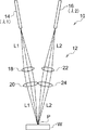
- Fig. 1A is a diagram illustrating an example of a configuration of a laser processing device according to a first exemplary embodiment, and a beam spot of the laser processing device.
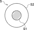
- Fig. 1B is an enlarged view of a superimposition spot.
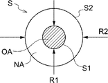
- Fig. 1C is an enlarged view of a superimposition spot.
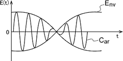
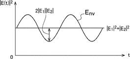
- Fig. 2A is a graph for explaining principles of a laser processing device according to an exemplary embodiment, and is a graph illustrating an example of a mode of time-wise changes in a carrier component and an envelope component.
- Fig. 2B is a graph for explaining principles of a laser processing device according to an exemplary embodiment, and is a graph illustrating an example of intensity modulation components for processing frequencies.
- Fig. 1A is a diagram illustrating an example of a configuration of a laser processing device according to a first exemplary embodiment, and a beam spot of the laser processing device.
- Fig. 1B is an enlarged view of a superimposition spot.
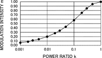
- FIG. 2C is a graph for explaining principles of a laser processing device according to an exemplary embodiment, and is a graph illustrating an example of a mode of change to modulation intensity with respect to changes in power ratio.
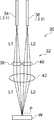
- Fig. 3 is a graph illustrating an example of a configuration of a laser processing device according to a second exemplary embodiment.
- Fig. 4 is a graph illustrating an example of a configuration of a laser processing device according to a third exemplary embodiment.
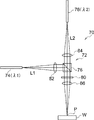
- Fig. 5A is a diagram illustrating an example of a configuration of a laser processing device according to a fourth exemplary embodiment.
- Fig. 5B is a diagram illustrating a modified example of a configuration of a laser processing device according to the fourth exemplary embodiment.
- FIG. 6A is a diagram illustrating an example of a configuration of a 3D printer according to a fifth exemplary embodiment.
- Fig. 6B is a diagram illustrating an example of a mode of a metal powder/conveyance gas channel with a shielding gas channel in cases in which a nozzle is viewed from a leading end.
- Fig. 7 is a block diagram illustrating an example of a hardware configuration of an electrical system of a laser processing device according to an exemplary embodiment.
- Fig. 8 is a conceptual diagram illustrating an example of a mode in which a program is installed to a laser processing device from a storage medium stored with the program.
- the laser processing device 10 includes an optical system 12, a laser source 14, and a laser source 16.
- the laser processing device 10 includes an optical system 12, a laser source 14, and a laser source 16.
- the laser source 14 and the laser source 16 are heat sources that supply heat during processing.
- a solid-state laser, a fiber laser, or the like may be employed therefor in the present exemplary embodiment, but there are no particular limitations thereto.
- the wavelength of the laser source 14 is ⁇ 1, the wavelength of the laser source 16 is ⁇ 2, and both of these wavelengths are different ( ⁇ 1 ⁇ ⁇ 2).
- wavelengths within a 1.00 ⁇ m band may be set as the wavelengths ⁇ 1 and ⁇ 2.
- the laser sources 14 and 16 are typically continuous wave (CW) types, pulsed light may be employed.
- the polarization state of the laser lights of the laser sources 14 and 16 according to the present exemplary embodiment is one of linear polarization.
- circularly polarized light may be employed, or one laser source may be a source of circularly polarized light and the other laser source may be a source of linearly polarized light.
- the optical system 12 is a section where light emitted from the laser source 14 and light emitted from the laser source 16 are each independently focused. As illustrated as an example in Fig. 1A, the optical system 12 is configured including: a lens 18 and a lens 20 that focus a light beam L1 emitted from the laser source 14; and a lens 22 and a lens 24 that focus a light beam L2 emitted from the laser source 16.
- the light beam L1 emitted from the laser source 14 and the light beam L2 emitted from the laser source 16 are each focused on the surface of a workpiece W after having been focused by the optical system 12, thereby forming a spot S, which is a spot where a laser beam spot (focus point) of each laser beam is superimposed on a processing point P (a region where processing is carried out on the workpiece W).
- a spot S which is a spot where a laser beam spot (focus point) of each laser beam is superimposed on a processing point P (a region where processing is carried out on the workpiece W).
- the formation position of the superimposition spot S on the workpiece W is not necessarily limited to the surface of the workpiece W, and the superimposition spot S may be formed inside the workpiece W in accordance with the material and the like of the workpiece W.
- Fig. 1B illustrates an enlarged view of a superimposition spot S.
- the superimposition spot S according to the present exemplary embodiment is formed by superimposing the spot S1 from the laser source 14 (the light beam L1) with the spot S2 from the laser source 16 (the light beam L2).
- the energy density in the region where the spot S1 is superimposed with the spot S2 is higher than the energy density of regions where the spot S1 is not superimposed with the spot S2.
- the superimposition spot S is formed such that the spot S2 encompasses the spot S1 as illustrated as an example in Fig. 1B, the superimposition state of the spot S1 with the spot S2 is not limited thereto.
- the shapes of the spots S, S1, and S2 are circular shapes, there is no limitation thereto.
- an appropriate shape such as a straight line shape or a rectangular shape may be selected, and the shapes of the spots may differ from one another. Note that the superimposition state of the spot S1 with the spot S2 is described in detail later.
- a region in which a spot S1 and a spot S2 are superimposed (the region of spot S1 in the example illustrated in Fig. 1C) is referred to as a "superimposition region OA", and a region in which the spot S1 and the spot S2 are not superimposed is referred to as a "no-superimposition region NA" (the region having only spot S2 in the example illustrated in Fig. 1C).
- a focus diameter (spot size) R1 of the spot S1 and a focus diameter (spot size) R2 of the spot S2 are defined as illustrated as an example in Fig. 1C.
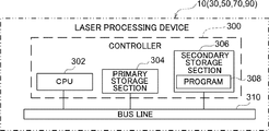
- the laser processing device 10 includes a controller 300.
- the controller 300 includes a CPU 302 serving as a central processing unit, a primary storage section 304, and a secondary storage section 306.
- Examples of the primary storage section 304 include RAM serving as random access memory.
- Examples of the secondary storage section 306 include ROM serving as read-only memory. Note that other examples of the secondary storage section 306 include non-volatile memory such as electrically erasable programmable read only memory (EEPROM) or flash memory.
- EEPROM electrically erasable programmable read only memory
- the secondary storage section 306 stores various programs including a program 308, various profiles such as a beam profile and an input heat profile, various parameters, and the like.
- the CPU 302, the primary storage section 304, and the secondary storage section 306 are connected to one another through a bus line 308. Accordingly, the CPU 302 reads the various programs from the secondary storage section 306, expands the various programs into the primary storage section 304, and executes each of the various programs.
- the CPU 302 operates as a controller according to technology disclosed herein by executing the program 308. Namely, when performing laser processing, the CPU 302 controls the input heat profile at a region where there are not two overlapping focus points, after having caused melting of the workpiece in the region where the two focus points have been overlapped.
- the absorption efficiency of the laser light can be raised by initially melting a portion of the surface of the workpiece using laser light emission.
- the superimposition spot S where the two spots S1 and S2 are superimposed is focused on a processing point P, so as to first cause slight melting in the highly focused (high energy density) superimposition region OA.
- the highly focused (high energy density) superimposition region OA one laser beam is focused, the surface of the workpiece W is melted by the focused laser beam, and processing characteristics are improved compared to performing cutting processing or welding processing with the same laser beam profile as-is.
- the CPU 302 can independently control suitable beam profiles typical for executing cutting processing and welding processing, enabling processing to be performed with high energy efficiency.
- the superimposition region OA which is a region where the spots of two laser lights having different wavelengths are superimposed, heterodyne interference occurs due to interference between the two laser lights, and the heterodyne interference is used in the laser processing.
- heterodyne interference is caused by superimposing the laser beams having the wavelengths ⁇ 1 and ⁇ 2 (in other words, optical frequencies of ⁇ 1 and ⁇ 2). This then generates a superimposition beam of a carrier component expressed by frequency ( ⁇ 1 + ⁇ 2)/2 and an envelope component expressed by ( ⁇ 1 - ⁇ 2)/2.
- the frequencies ⁇ 1 and ⁇ 2 in accordance with the processing conditions, the frequency ( ⁇ 1 + ⁇ 2)/2 of the carrier component acts like a third wavelength ⁇ 3 that influences the absorption characteristics of the workpiece W, and the CPU 302 controls the processing characteristics using the frequency ( ⁇ 1 - ⁇ 2)/2 of the envelope component.
- the absorption characteristics of the superimposition region OA are determined by the carrier frequency and the absorption characteristics of the workpiece, and the absorption characteristics in the superimposition region OA can be raised by appropriately selecting the carrier frequency. Further, the carrier frequency could also be set such that such that the reflection ratio is raised at the superimposition region OA, if necessary. In such a case, the combination of the wavelengths ⁇ 1 and ⁇ 2 can be appropriately selected by considering the absorption wavelength characteristics of the workpiece W.
- Fig. 2A illustrates the carrier component Car and the envelope component Env on a plot having time on the horizontal axis and electric field E on the vertical axis.
- the frequency (processing frequency) employed in the processing of the laser processing device 10 is ⁇ c
- the intensity of the processing frequency ⁇ c can be described as being rapidly modulated by the frequency ⁇ e of the envelope component.
- the reflection ratio characteristics or the absorption characteristics for a material are similar to the characteristics for the laser light having frequency ⁇ c, and the laser light having frequency ⁇ c behaves as if intensity modulated by the frequency ⁇ e.
- Equation 4 the optical intensity
- a plot of Equation 4 yields, for example, Fig. 2B.
- Fig. 2B is a plot obtained from the above, of the intensity modulation component for the processing frequency ⁇ c.
- Fig. 2C illustrates an amplitude magnitude (modulation intensity or brightness) of an interference signal generated by laser light from the laser source 14 and the laser source 16, which are two laser sources having different wavelengths.
- Fig. 2C has power ratio k on the horizontal axis, and change in the modulation intensity m is plotted against the power ratio k.
- k 1, namely, in cases in which the power of the laser lights from the two laser sources are equal, this means that the amplitude 2
- the polarization of laser light from the laser source 14 and the laser source 16 is preferably linear polarization for both laser lights. It is most efficient to employ the characteristics of light beams produced by interference between linearly polarized light beams. However, interference between linearly polarized light and circularly polarized light (or randomly polarized light or unpolarized light), or interference between circularly polarized light beams can be employed. Although laser light sent using an optical fiber can be employed, for interference effects to be expected, it is preferable to employ laser light that has propagated through a single-mode optical fiber or low-dimension mode laser light delivered through an optical fiber capable of high-mode delivery.
- Randomly polarized light is polarized light in which the linear polarization direction of the light is aperiodically changed.
- Unpolarized light is light for which the linear polarization direction of the light is evenly mixed over a 360° range.
- the number of spots is three or more in some cases since three or more laser sources can be employed in technology disclosed herein.
- three or more spots for example, three spots S3, S4, and S5 using three laser sources
- a mode in which the spot S3 and the spot S4 are contained within the spot S5 is conceivable as an example.
- modes in which the spot S3 and the spot S4 do not overlap at all, modes in which the spot S3 is contained within the spot S4, and the like are conceivable inside the spot S5.
- a mode in which a portion of at least one out of the spot S3 or the spot S4 falls outside of the spot S5 is also conceivable.
- Employing three or more spots enables the CPU 302 to control the input heat profile with high precision.
- the present example case is an example case in which a metal sheet is cut by both laser processing devices and the quality of the processing is compared.
- Comparative Example In the laser processing device according to related technology that employs a single laser source, mild steel having a plate thickness of 1.5 mm was cut using a laser light of a 900W laser source constrained to a spot having a 300 ⁇ m focus diameter (diameter). It was found that a cut could be made with excellent product quality as a result. A cuff width needs to be controlled as a cutting margin (a width needed to blow away the melted metal), and an optimum width was 300 ⁇ m.
- the laser processing device and the laser processing method according to the present exemplary embodiment achieve a laser processing device and a laser processing method having excellent energy efficiency by superimposing emitted light from plural laser sources having different wavelengths (in other words, optical frequencies) as described above at the processing point and forming the superimposition spot S as illustrated in Fig. 1B. Further, a laser processing device and a laser processing method are achieved in which the CPU 302 can control the input heat (energy density) input to the workpiece by controlling the overlap distribution of the beam.
- the CPU 302 controls the beam profile (the shape of the superimposition spot S) at the focus point of the plural beams (having different wavelengths and a focus characteristics), and input heat characteristics and absorption characteristics of the workpiece can be independently controlled by employing interference effects between the laser lights caused by the superimposition, thus achieving cutting or welding processing having high energy efficiency.
- the laser processing device 30 includes a laser source 34, a laser source 36, and an optical system 32.
- the wavelength of the laser source 34 is ⁇ 1
- the wavelength of the laser source 36 is ⁇ 2 ( ⁇ ⁇ 1).
- the optical system 32 is configured including lenses 38, 40, and 42.
- the lens 38 focuses a light beam L1 from the laser source 34.
- the lens 40 focuses a light beam L2 from the laser source 36.
- the light beam L1 focused by the lens 38 and the light beam L2 focused by the lens 40 are each further focused by the lens 42, and a superimposition spot S (see Fig. 1B) are formed at the processing point P of the workpiece W as a result.
- the laser processing device enables the optical system to be configured more simply than in the exemplary embodiment above since the number of lenses is reduced by making some of the lenses common.
- the laser processing device 50 includes a laser source having a wavelength ⁇ 1, a laser source having a wavelength ⁇ 2 (these are omitted from the drawings), and an optical system 52.
- the optical system 52 is configured including mirrors 54 and 56, and a lens 58.
- a light beam L1 from the laser source having the wavelength ⁇ 1 is reflected at substantially a right angle by the mirror 54 and aimed toward the lens 58, and is focused at the processing point P of the workpiece W.
- a light beam L2 from the laser source having the wavelength ⁇ 2 is reflected at substantially a right angle by the mirror 56 and aimed toward the lens 58, and is focused at the processing point P of the workpiece W.
- the superimposition spot S is formed at the processing point as a result.
- the laser processing device enables the optical system to be configured more simply than in the exemplary embodiment above since the number of lenses is further reduced by applying mirrors to the optical system.
- Fig. 5A illustrates a laser processing device 70 according to the present exemplary embodiment.
- Fig. 5B illustrates a laser processing device 90, which is a modified example of the laser processing device 70.
- the laser processing device 70 includes a laser source 74, a laser source 76, and an optical system 72.
- the wavelength of the laser source 74 is ⁇ 1
- the wavelength of the laser source 76 is ⁇ 2 ( ⁇ ⁇ 1).
- Laser light of the laser source 74 and laser light of the laser source 76 are both linearly polarized and polarized wave directions are orthogonal to each other.
- the optical system 72 includes a polarizing prism 78, a 1/4 waveplate 80, and lenses 82, 84, and 86.
- the polarizing prism 78 is an optical element that multiplexes two linearly polarized light beams having orthogonal wave polarization directions.
- the polarizing prism 78 multiplexes the laser light (light beam L1) from the laser source 74 with the laser light (light beam L2) from the laser source 76 and transmits the multiplexed laser light toward the 1/4 waveplate 80.
- the 1/4 waveplate 80 is an element that converts incident linearly polarized light into circularly polarized light.
- the 1/4 waveplate 80 converts, into circularly polarized light, the laser light from the laser source 74 and the laser light from the laser source 76 that have been multiplexed by the polarizing prism 78, and forms the superimposition spot S at the processing point P of the workpiece W.
- the laser processing device has an advantageous effect of enabling heterodyne interference to be stabilized by using a 1/4 waveplate when employing the above described heterodyne interference between mutually orthogonally linearly polarized light beams respectively having a wavelength ⁇ 1 and a wavelength ⁇ 2, which are similar wavelengths.
- the laser processing device enables dependency on polarization of the processing light to be reduced when, for example, cutting metal, since the laser light at the processing point P is circularly polarized light.
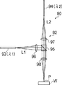
- the laser processing device 90 includes a laser source 93, a laser source 94, and an optical system 92.
- the wavelength of the laser source 93 is ⁇ 1
- the wavelength of the laser source 94 is ⁇ 2.
- the polarization state of the laser light of each laser source is one of circular polarization.
- the optical system 92 is configured including a dichroic mirror 95 and lenses 96, 97, and 98.
- the dichroic mirror 95 is an optical element that multiplexes two laser light beams having different wavelengths by reflecting one light beam and passing the other light beam. As illustrated as an example in Fig. 5B, multiplexing is performed by reflecting the light beam L1 from the laser source 93 and passing the light beam L2 from the laser source 94. The multiplexed light beam L1 and the light beam L2 are focused by the lens 98 and the superimposition spot S is formed at the processing point P of the workpiece W.
- the laser processing device has an advantageous effect of enabling the optical system to be simplified since employing a dichroic mirror according to the present exemplary embodiment eliminates the need to employ a 1/4 waveplate, particularly when applying, as the wavelength ⁇ 1 and the wavelength ⁇ 2, a combination of wavelengths having frequencies separated by a predetermined wavelength (for example, a combination of an infrared region wavelength and a visible wavelength in a 1 ⁇ m band). Further, the laser processing device according to the present exemplary embodiment is able to achieve a less expensive laser processing device, since a dichroic mirror is less expensive than a polarizing prism and there is no need to employ a 1/4 waveplate.
- the 3D printer is apparatus that shapes solid objects (three-dimensional objects) based on 3D CAD data or 3D CG data.
- the 3D printer employs, for example, a laminated shaping method as the shaping method. Minute focus diameter laser spots, namely, melted spots, are requested for the 3D printer to form a laminated object in some cases.
- the laser processing device according to the exemplary embodiments above is also suitable for achieving small melted spots such as those needed in the 3D printer.
- laminated object production can be achieved with small melted spots by the CPU 302 independently controlling a region of strongest absorption and melting due to the superimposition region OA of the superimposition spot S, and a region that adjusts the amount of heat introduced to the entire object by the no-superimposition region NA, at the processing point P of the workpiece W.
- the 3D printer includes a processing light generator 100 and a metal powder supplying mechanism 200.
- the processing light generator 100 is a section having a similar function to the laser processing device described above.
- the processing light generator 100 includes a laser source 102 that outputs laser light beams having plural wavelengths (a case of two wavelengths is illustrated in the example illustrated in Fig. 6A) and a lens 104.
- a light beam L1 having a wavelength ⁇ 1 and a light beam L2 having a wavelength ⁇ 2 output from the laser source 102 are focused by the lens 104 and the superimposition spot S is formed at the processing point P for forming the laminated shape.
- the metal powder supplying mechanism 200 is configured including a nozzle 202; a metal powder source and a conveyance section therefor, which are omitted from the drawings; a conveyance gas and a conveyance section therefor; and a shielding gas and a conveyance section therefor.
- the powder is not limited to a metal; a ceramic, a resin, or the like may be employed.
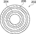
- the nozzle 202 includes a metal powder/conveyance gas channel 204 for supplying the metal powder serving as a laminating material (a material for performing lamination) together with a conveyance gas (for example, nitrogen gas) as a powder-mixed gas PG, and a shielding gas channel 206 for supplying a shielding gas SG (for example, nitrogen gas) for shielding the processing point P from the exterior during lamination.
- a conveyance gas for example, nitrogen gas
- SG for example, nitrogen gas
- the nozzle 202 is configured such that the metal powder/conveyance gas channel 204 and the shielding gas channel 206 are disposed in a concentric circle arrangement as viewed from the leading end of the nozzle 202.
- the processing light generator 100 laminating is performed by ejecting metal powder from the nozzle 202 while the light beams L1 and L2 are emitted on the processing point.
- the processing point P where laminating is being performed is shielded by the shielding gas SG and an atmosphere of the conveyance gas is maintained around the processing point P.
- the powder-mixed gas PG is discharged from the nozzle 202 and the light beams L1 and L2 from the laser source 102 are emitted onto the metal powder included in the powder-mixed gas PG.
- the energy of the spot S is received at the processing point P, the heated metal powder melts, and a laminated portion of solidified metal is formed.
- the CPU 302 controls the processing characteristics by causing the energy of the no-superimposition region NA, which has a lower energy density than the superimposition region OA, to be absorbed, thereby employing the superimposition spot S to achieve an advantageous effect, namely, an advantageous effect of improved energy efficiency.
- a mode may be configured such that laser light from a single laser source is split to form the superimposition spot S.
- configuration may be made such that, for example, laser light from a single laser source is split into plural laser light beams by a beam splitter or the like and the split plural laser light beams have the characteristics described above (energy density, encompassing relationship, and the like) so as to form the superimposition spot S.
- the advantageous effects of the superimposition spot S according to technology disclosed herein can be achieved using a laser processing device having a simpler configuration.
- the program 308 does not necessarily need to be pre-stored on the secondary storage section 306.
- the program 308 may be first stored on an arbitrarily selected portable storage medium 400, such as an SSD, USB memory, or a CD-ROM.
- the program 308 of the storage medium 400 is installed to the laser processing device 10 (30, 50, 70, 90), and the installed program 308 is executed by the CPU 302.
- the program 308 may be stored in a storage section such as another computer or a server device connected to the laser processing device 10 (30, 50, 70, 90) through a communication network (not illustrated in the drawings), and the program 308 may be downloaded by the laser processing device 10 (30, 50, 70, 90) when needed. In such cases, the downloaded program 308 is executed by the CPU 302.
- controller according to technology disclosed herein is implemented by a software configuration that employs a computer
- technology disclosed herein is not limited thereto.
- the controller according to technology disclosed herein may be implemented using a hardware configuration alone, such as a field-programmable gate array (FPGA) or an application specific integrated circuit (ASIC).
- the controller according to technology disclosed herein may be implemented by a combination of software configuration and hardware configuration.
- laser processing device 12 optical system 14, 16 laser source 18, 20, 22, 24 lens 30 laser processing device 32 optical system 34, 36 laser source 38, 40, 42 lens 50 laser processing device 52 optical system 54, 56 mirror 58 lens 70 laser processing device 72 optical system 74, 76 laser source 78 polarizing prism 80 1/4 waveplate 82, 84, 86 lens 90 laser processing device 92 optical system 93, 94 laser source 95 dichroic mirror 96, 97, 98 lens 100 processing light generator 102 laser source 104 lens 200 metal powder supplying mechanism 202 nozzle 204 metal powder/conveyance gas channel 206 shielding gas channel Car carrier component Env envelope component L1, L1 light beam PG powder-mixed gas SG shielding gas P processing point R1, R2 focus diameter S superimposition spot S1 to S5 spot OA superimposition region NA no-superimposition region W workpiece
Landscapes
- Engineering & Computer Science (AREA)
- Physics & Mathematics (AREA)
- Optics & Photonics (AREA)
- Mechanical Engineering (AREA)
- Plasma & Fusion (AREA)
- Manufacturing & Machinery (AREA)
- Materials Engineering (AREA)
- Chemical & Material Sciences (AREA)
- General Health & Medical Sciences (AREA)
- Toxicology (AREA)
- Health & Medical Sciences (AREA)
- Automation & Control Theory (AREA)
- Laser Beam Processing (AREA)
- Powder Metallurgy (AREA)
Abstract
Un dispositif de traitement au laser comprend plusieurs sources laser et une section de focalisation qui focalise des faisceaux lumineux respectifs desdites plusieurs sources laser de façon à former plusieurs points de focalisation sur une pièce à usiner et qui focalise de telle sorte que des parties respectives d'au moins certains desdits plusieurs points de focalisation se chevauchent.
Priority Applications (1)
| Application Number | Priority Date | Filing Date | Title |
|---|---|---|---|
| US15/772,469 US20180333807A1 (en) | 2016-03-18 | 2017-03-17 | Laser processing device, three-dimensional shaping device, and laser processing method |
Applications Claiming Priority (2)
| Application Number | Priority Date | Filing Date | Title |
|---|---|---|---|
| JP2016056211A JP6551275B2 (ja) | 2016-03-18 | 2016-03-18 | レーザ加工装置、三次元造形装置、及びレーザ加工方法 |
| JP2016-056211 | 2016-03-18 |
Publications (1)
| Publication Number | Publication Date |
|---|---|
| WO2017159874A1 true WO2017159874A1 (fr) | 2017-09-21 |
Family
ID=59850770
Family Applications (1)
| Application Number | Title | Priority Date | Filing Date |
|---|---|---|---|
| PCT/JP2017/011017 Ceased WO2017159874A1 (fr) | 2016-03-18 | 2017-03-17 | Dispositif de traitement au laser, dispositif de mise en forme tridimensionnelle et procédé de traitement au laser |
Country Status (3)
| Country | Link |
|---|---|
| US (1) | US20180333807A1 (fr) |
| JP (1) | JP6551275B2 (fr) |
| WO (1) | WO2017159874A1 (fr) |
Cited By (5)
| Publication number | Priority date | Publication date | Assignee | Title |
|---|---|---|---|---|
| CN109663915A (zh) * | 2018-12-28 | 2019-04-23 | 淮阴工学院 | 一种激光增材制造防裂装置 |
| EP3597406A1 (fr) * | 2018-07-18 | 2020-01-22 | Concept Laser GmbH | Appareil de fabrication additive d'objets tridimensionnels |
| EP3597404A1 (fr) * | 2018-07-18 | 2020-01-22 | Concept Laser GmbH | Procédé de fonctionnement d'un appareil de fabrication additive d'objets tridimensionnels |
| WO2020016726A1 (fr) * | 2018-07-18 | 2020-01-23 | Cl Schutzrechtsverwaltungs Gmbh | Procédé de fonctionnement d'un appareil de fabrication additive d'objets tridimensionnels |
| CN116685425A (zh) * | 2020-11-30 | 2023-09-01 | 株式会社斯库林集团 | 光学装置及三维造型装置 |
Families Citing this family (14)
| Publication number | Priority date | Publication date | Assignee | Title |
|---|---|---|---|---|
| JP6600278B2 (ja) * | 2016-06-07 | 2019-10-30 | 三菱重工業株式会社 | 選択型ビーム積層造形装置及び選択型ビーム積層造形方法 |
| JP6495989B1 (ja) * | 2017-10-02 | 2019-04-03 | 株式会社アマダホールディングス | プログラム作成装置、溶接システム、及びプログラム作成方法 |
| US20190210151A1 (en) * | 2018-01-08 | 2019-07-11 | General Electric Company | Systems and methods for additive manufacturing using pressurized consolidation devices |
| JP6534470B1 (ja) * | 2018-03-30 | 2019-06-26 | 株式会社フジクラ | 照射装置、金属造形装置、金属造形システム、照射方法、及び金属造形物の製造方法 |
| EP3760348A4 (fr) | 2018-04-20 | 2021-12-01 | Taiyo Nippon Sanso Corporation | Procédé pour la fabrication d'un objet modelé métallique |
| KR102129322B1 (ko) * | 2018-05-09 | 2020-07-03 | 중앙대학교 산학협력단 | 레이저를 이용한 3차원 금속 프린팅 장치 및 방법 |
| KR102228433B1 (ko) * | 2019-05-08 | 2021-03-16 | 레이저쎌 주식회사 | 레이저 리플로우 장치의 레이저 가압 헤드 모듈 |
| JP7041238B1 (ja) | 2020-12-07 | 2022-03-23 | 株式会社ソディック | 積層造形装置の較正方法及び積層造形装置 |
| CN114762918B (zh) * | 2021-01-15 | 2023-07-25 | 中国科学院上海光学精密机械研究所 | 一种高强度钢激光拼焊部件制造方法 |
| CN113477948B (zh) * | 2021-06-29 | 2022-05-24 | 华南理工大学 | 一种激光选区熔化的控制系统、方法及装置 |
| EP4403362A4 (fr) * | 2021-09-16 | 2025-08-13 | Nikon Corp | Système de fabrication |
| JP2023173780A (ja) * | 2022-05-26 | 2023-12-07 | 住友重機械工業株式会社 | レーザ加工装置およびレーザ加工方法 |
| CN117505890A (zh) * | 2023-12-05 | 2024-02-06 | 苏州工业职业技术学院 | 一种激光金属3d打印装置及其闭环控制系统和方法 |
| CN120421693A (zh) * | 2025-06-19 | 2025-08-05 | 苏州菲镭泰克激光技术有限公司 | 复合材料或不同体位加工的多光束、多光斑一体式振镜 |
Citations (5)
| Publication number | Priority date | Publication date | Assignee | Title |
|---|---|---|---|---|
| JPS63299883A (ja) * | 1987-05-29 | 1988-12-07 | Mitsubishi Electric Corp | レ−ザ加工装置 |
| JP2002067171A (ja) * | 2000-08-25 | 2002-03-05 | Canon Inc | 目的物生成装置、目的物生成方法、及び記憶媒体 |
| US20060237402A1 (en) * | 2005-04-22 | 2006-10-26 | Takahiro Nagashima | Laser welding method and laser welding apparatus |
| JP2008212998A (ja) * | 2007-03-06 | 2008-09-18 | Seiko Epson Corp | レーザ加工装置、レーザ加工方法、基板の分割方法、及び電気光学装置の製造方法 |
| JP2015199110A (ja) * | 2014-04-10 | 2015-11-12 | アイシン精機株式会社 | レーザ溶接方法 |
Family Cites Families (3)
| Publication number | Priority date | Publication date | Assignee | Title |
|---|---|---|---|---|
| US5393482A (en) * | 1993-10-20 | 1995-02-28 | United Technologies Corporation | Method for performing multiple beam laser sintering employing focussed and defocussed laser beams |
| JP2007301980A (ja) * | 2006-04-10 | 2007-11-22 | Matsushita Electric Ind Co Ltd | レーザ積層方法およびレーザ積層装置 |
| CN104190928A (zh) * | 2014-08-18 | 2014-12-10 | 中国科学院重庆绿色智能技术研究院 | 一种多波长激光选区快速成形系统及方法 |
-
2016
- 2016-03-18 JP JP2016056211A patent/JP6551275B2/ja not_active Expired - Fee Related
-
2017
- 2017-03-17 US US15/772,469 patent/US20180333807A1/en not_active Abandoned
- 2017-03-17 WO PCT/JP2017/011017 patent/WO2017159874A1/fr not_active Ceased
Patent Citations (5)
| Publication number | Priority date | Publication date | Assignee | Title |
|---|---|---|---|---|
| JPS63299883A (ja) * | 1987-05-29 | 1988-12-07 | Mitsubishi Electric Corp | レ−ザ加工装置 |
| JP2002067171A (ja) * | 2000-08-25 | 2002-03-05 | Canon Inc | 目的物生成装置、目的物生成方法、及び記憶媒体 |
| US20060237402A1 (en) * | 2005-04-22 | 2006-10-26 | Takahiro Nagashima | Laser welding method and laser welding apparatus |
| JP2008212998A (ja) * | 2007-03-06 | 2008-09-18 | Seiko Epson Corp | レーザ加工装置、レーザ加工方法、基板の分割方法、及び電気光学装置の製造方法 |
| JP2015199110A (ja) * | 2014-04-10 | 2015-11-12 | アイシン精機株式会社 | レーザ溶接方法 |
Cited By (7)
| Publication number | Priority date | Publication date | Assignee | Title |
|---|---|---|---|---|
| EP3597406A1 (fr) * | 2018-07-18 | 2020-01-22 | Concept Laser GmbH | Appareil de fabrication additive d'objets tridimensionnels |
| EP3597404A1 (fr) * | 2018-07-18 | 2020-01-22 | Concept Laser GmbH | Procédé de fonctionnement d'un appareil de fabrication additive d'objets tridimensionnels |
| WO2020016722A1 (fr) * | 2018-07-18 | 2020-01-23 | Cl Schutzrechtsverwaltungs Gmbh | Appareil de fabrication additive d'objets tridimensionnels |
| WO2020016726A1 (fr) * | 2018-07-18 | 2020-01-23 | Cl Schutzrechtsverwaltungs Gmbh | Procédé de fonctionnement d'un appareil de fabrication additive d'objets tridimensionnels |
| CN109663915A (zh) * | 2018-12-28 | 2019-04-23 | 淮阴工学院 | 一种激光增材制造防裂装置 |
| CN109663915B (zh) * | 2018-12-28 | 2024-03-26 | 淮阴工学院 | 一种激光增材制造防裂的方法 |
| CN116685425A (zh) * | 2020-11-30 | 2023-09-01 | 株式会社斯库林集团 | 光学装置及三维造型装置 |
Also Published As
| Publication number | Publication date |
|---|---|
| JP6551275B2 (ja) | 2019-07-31 |
| US20180333807A1 (en) | 2018-11-22 |
| JP2017170454A (ja) | 2017-09-28 |
Similar Documents
| Publication | Publication Date | Title |
|---|---|---|
| WO2017159874A1 (fr) | Dispositif de traitement au laser, dispositif de mise en forme tridimensionnelle et procédé de traitement au laser | |
| JP7013413B2 (ja) | レーザ加工装置及びレーザ加工方法 | |
| JP7075274B2 (ja) | 三次元プリンティングのための装置、システムおよび方法 | |
| US10418774B2 (en) | Spectrally multiplexing diode pump modules to improve brightness | |
| US9917416B2 (en) | Semiconductor laser oscillator | |
| US9636775B2 (en) | Composite beam generator and powder melting or sintering method using the same | |
| US10283934B2 (en) | Semiconductor laser oscillator | |
| US20150260985A1 (en) | Laser processing apparatus and laser processing method | |
| US9129717B2 (en) | EUV excitation light source with a laser beam source and a beam guide device for manipulating the laser beam | |
| JP2011523723A (ja) | ビーム形成装置およびビーム形成方法 | |
| US10300558B2 (en) | Laser processing machine and laser cutting method | |
| KR20140065547A (ko) | 레이저 가공 장치 및 방법 | |
| CN203956324U (zh) | 用于激光切割镀膜板或涂层板的激光切割机 | |
| JP2018528081A (ja) | Dcb構造体の重ね溶接のためのレーザー加工機および方法 | |
| KR101987192B1 (ko) | 가공물 절단 장치 | |
| JP6043773B2 (ja) | ダイレクトダイオードレーザ光による板金の加工方法及びこれを実行するダイレクトダイオードレーザ加工装置 | |
| CN111799655A (zh) | 高功率半导体激光器 | |
| KR20140008102A (ko) | 파이버 레이저 가공 장치 | |
| CN113618231A (zh) | 激光加工装置 | |
| KR20160140212A (ko) | 레이저 가공장치 및 레이저 가공방법 | |
| EP3641080B1 (fr) | Dispositif et système d'irradiation à faisceau laser | |
| JP6568716B2 (ja) | レーザ加工装置及びレーザ加工方法 | |
| KR101098259B1 (ko) | 레이저 스크라이브 방법 및 장치 | |
| CN101486128B (zh) | 具有电子遮蔽系统的激光装置 | |
| JP2016078046A (ja) | ダイレクトダイオードレーザ加工装置及びこれを用いた金属板の加工方法 |
Legal Events
| Date | Code | Title | Description |
|---|---|---|---|
| WWE | Wipo information: entry into national phase |
Ref document number: 15772469 Country of ref document: US |
|
| NENP | Non-entry into the national phase |
Ref country code: DE |
|
| 121 | Ep: the epo has been informed by wipo that ep was designated in this application |
Ref document number: 17766869 Country of ref document: EP Kind code of ref document: A1 |
|
| 122 | Ep: pct application non-entry in european phase |
Ref document number: 17766869 Country of ref document: EP Kind code of ref document: A1 |