WO2017161488A1 - Module de grossissement optique à courte distance, lunettes, casque et système de réalité virtuelle (vr) - Google Patents
Module de grossissement optique à courte distance, lunettes, casque et système de réalité virtuelle (vr) Download PDFInfo
- Publication number
- WO2017161488A1 WO2017161488A1 PCT/CN2016/076937 CN2016076937W WO2017161488A1 WO 2017161488 A1 WO2017161488 A1 WO 2017161488A1 CN 2016076937 W CN2016076937 W CN 2016076937W WO 2017161488 A1 WO2017161488 A1 WO 2017161488A1
- Authority
- WO
- WIPO (PCT)
- Prior art keywords
- lens
- short
- optical
- focal length
- amplifying module
- Prior art date
- Legal status (The legal status is an assumption and is not a legal conclusion. Google has not performed a legal analysis and makes no representation as to the accuracy of the status listed.)
- Ceased
Links
Images




Classifications
-
- G—PHYSICS
- G02—OPTICS
- G02B—OPTICAL ELEMENTS, SYSTEMS OR APPARATUS
- G02B27/00—Optical systems or apparatus not provided for by any of the groups G02B1/00 - G02B26/00, G02B30/00
- G02B27/01—Head-up displays
- G02B27/017—Head mounted
- G02B27/0172—Head mounted characterised by optical features
-
- G—PHYSICS
- G02—OPTICS
- G02B—OPTICAL ELEMENTS, SYSTEMS OR APPARATUS
- G02B27/00—Optical systems or apparatus not provided for by any of the groups G02B1/00 - G02B26/00, G02B30/00
- G02B27/0012—Optical design, e.g. procedures, algorithms, optimisation routines
-
- G—PHYSICS
- G02—OPTICS
- G02B—OPTICAL ELEMENTS, SYSTEMS OR APPARATUS
- G02B27/00—Optical systems or apparatus not provided for by any of the groups G02B1/00 - G02B26/00, G02B30/00
- G02B27/0025—Optical systems or apparatus not provided for by any of the groups G02B1/00 - G02B26/00, G02B30/00 for optical correction, e.g. distorsion, aberration
-
- G—PHYSICS
- G02—OPTICS
- G02B—OPTICAL ELEMENTS, SYSTEMS OR APPARATUS
- G02B27/00—Optical systems or apparatus not provided for by any of the groups G02B1/00 - G02B26/00, G02B30/00
- G02B27/01—Head-up displays
-
- G—PHYSICS
- G02—OPTICS
- G02B—OPTICAL ELEMENTS, SYSTEMS OR APPARATUS
- G02B27/00—Optical systems or apparatus not provided for by any of the groups G02B1/00 - G02B26/00, G02B30/00
- G02B27/09—Beam shaping, e.g. changing the cross-sectional area, not otherwise provided for
- G02B27/0938—Using specific optical elements
- G02B27/0977—Reflective elements
-
- G—PHYSICS
- G02—OPTICS
- G02B—OPTICAL ELEMENTS, SYSTEMS OR APPARATUS
- G02B27/00—Optical systems or apparatus not provided for by any of the groups G02B1/00 - G02B26/00, G02B30/00
- G02B27/10—Beam splitting or combining systems
-
- G—PHYSICS
- G02—OPTICS
- G02B—OPTICAL ELEMENTS, SYSTEMS OR APPARATUS
- G02B27/00—Optical systems or apparatus not provided for by any of the groups G02B1/00 - G02B26/00, G02B30/00
- G02B27/28—Optical systems or apparatus not provided for by any of the groups G02B1/00 - G02B26/00, G02B30/00 for polarising
-
- G—PHYSICS
- G02—OPTICS
- G02B—OPTICAL ELEMENTS, SYSTEMS OR APPARATUS
- G02B27/00—Optical systems or apparatus not provided for by any of the groups G02B1/00 - G02B26/00, G02B30/00
- G02B27/28—Optical systems or apparatus not provided for by any of the groups G02B1/00 - G02B26/00, G02B30/00 for polarising
- G02B27/286—Optical systems or apparatus not provided for by any of the groups G02B1/00 - G02B26/00, G02B30/00 for polarising for controlling or changing the state of polarisation, e.g. transforming one polarisation state into another
-
- G—PHYSICS
- G02—OPTICS
- G02B—OPTICAL ELEMENTS, SYSTEMS OR APPARATUS
- G02B5/00—Optical elements other than lenses
- G02B5/30—Polarising elements
-
- G—PHYSICS
- G02—OPTICS
- G02B—OPTICAL ELEMENTS, SYSTEMS OR APPARATUS
- G02B5/00—Optical elements other than lenses
- G02B5/30—Polarising elements
- G02B5/3083—Birefringent or phase retarding elements
-
- G—PHYSICS
- G02—OPTICS
- G02F—OPTICAL DEVICES OR ARRANGEMENTS FOR THE CONTROL OF LIGHT BY MODIFICATION OF THE OPTICAL PROPERTIES OF THE MEDIA OF THE ELEMENTS INVOLVED THEREIN; NON-LINEAR OPTICS; FREQUENCY-CHANGING OF LIGHT; OPTICAL LOGIC ELEMENTS; OPTICAL ANALOGUE/DIGITAL CONVERTERS
- G02F1/00—Devices or arrangements for the control of the intensity, colour, phase, polarisation or direction of light arriving from an independent light source, e.g. switching, gating or modulating; Non-linear optics
- G02F1/01—Devices or arrangements for the control of the intensity, colour, phase, polarisation or direction of light arriving from an independent light source, e.g. switching, gating or modulating; Non-linear optics for the control of the intensity, phase, polarisation or colour
-
- G—PHYSICS
- G06—COMPUTING OR CALCULATING; COUNTING
- G06T—IMAGE DATA PROCESSING OR GENERATION, IN GENERAL
- G06T19/00—Manipulating three-dimensional [3D] models or images for computer graphics
- G06T19/006—Mixed reality
-
- G—PHYSICS
- G06—COMPUTING OR CALCULATING; COUNTING
- G06T—IMAGE DATA PROCESSING OR GENERATION, IN GENERAL
- G06T3/00—Geometric image transformations in the plane of the image
- G06T3/04—Context-preserving transformations, e.g. by using an importance map
- G06T3/047—Fisheye or wide-angle transformations
-
- G—PHYSICS
- G06—COMPUTING OR CALCULATING; COUNTING
- G06T—IMAGE DATA PROCESSING OR GENERATION, IN GENERAL
- G06T3/00—Geometric image transformations in the plane of the image
- G06T3/40—Scaling of whole images or parts thereof, e.g. expanding or contracting
- G06T3/4053—Scaling of whole images or parts thereof, e.g. expanding or contracting based on super-resolution, i.e. the output image resolution being higher than the sensor resolution
-
- G—PHYSICS
- G02—OPTICS
- G02B—OPTICAL ELEMENTS, SYSTEMS OR APPARATUS
- G02B27/00—Optical systems or apparatus not provided for by any of the groups G02B1/00 - G02B26/00, G02B30/00
- G02B27/01—Head-up displays
- G02B27/0101—Head-up displays characterised by optical features
- G02B2027/0123—Head-up displays characterised by optical features comprising devices increasing the field of view
Definitions
- the invention relates to the technical field of optical instruments, in particular to short-distance optical amplifying modules, glasses, helmets and VR systems.
- the module In order to meet the imaging quality of the optical amplifying module, the module usually includes a plurality of optical devices. As shown in FIG. 1 , the reflective polarizing plate 01 is sequentially included from the image side to the object side.
- the first phase retarder 02, the lens unit 03, and the second phase retarder 04, in the lens unit 03, the optical surface close to the second phase retarder 04 is a transflective optical surface.
- the optical image on the object side is transmitted and amplified by the lens unit 03, then reflected on the reflective polarizing plate 01, and then subjected to secondary amplification by the lens unit 03, and finally through the reflective polarization.
- the sheet 01 enters the line of sight of the human eye, wherein the core component that affects the magnifying effect of the optical image is the lens unit.
- an optical amplifying module composed of a plurality of optical components is often large in size and volume, and in particular, cannot meet the requirements of a smart VR (Virtual Reality) wearable device. Structural requirements. That is, it is necessary to design a short-distance optics that still has a high magnification in a small space for the VR device.
- VR devices are also more focused on providing a good sense of user experience, which in turn requires VR devices to achieve a better field of view, a larger range of eye movements, high-quality imaging effects and other technical purposes. These technical purposes are directly related to the optical properties of the lens group described above.
- a short-distance optical amplifying module is provided to meet the requirements of being able to be used in a small-sized VR device, and the VR device has a better viewing angle, a larger eye movement range, and a high quality.
- the purpose of the imaging effect is also provided.
- a short-distance optical amplifying module comprising a reflective polarizing plate, a first phase retarder, a third lens and a second phase retarder arranged in sequence, wherein the reflective polarizer, the first phase retarder, and the third lens And a first lens disposed at either position on either side of any one of the second phase retarders, and any one of the reflective polarizer, the first phase retarder, the third lens, and the second phase retarder a second lens is disposed at any position on both sides of the device, wherein: an optical surface of the third lens adjacent to the second phase retarder is a transflective optical surface; and a first focal length of the third lens F3 satisfies the following condition: 1F ⁇ f3 ⁇ 2F, where F is the system focal length of the short-distance optical amplifying module.
- the first focal length f3 of the third lens satisfies the following condition: 1.5F ⁇ f3 ⁇ 2F.
- the focal length fS6 of the transflective optical surface satisfies the following condition: 1.5F ⁇ fS6 ⁇ 5F.
- the focal length fS5 of the optical surface close to the second lens among the third lenses satisfies the following condition:
- the system focal length F of the short-distance optical amplifying module satisfies the following condition: 10 mm ⁇ F ⁇ 32 mm.
- the focal length f2 of the second lens satisfies the following condition: 2F ⁇ -f2.
- the focal length fS3 of the optical surface close to the first lens in the second lens satisfies the following condition:
- the focal length fS4 of the optical surface of the second lens close to the third lens satisfies the following condition:
- the focal length f1 of the first lens satisfies the following condition: 4F ⁇ f1.
- a focal length fS2 of the optical surface of the first lens close to the second lens is equal to a focal length f1 of the first lens.
- the optical amplifying module has a thickness of 8 mm to 30 mm.
- the aperture D through which the light beam that the first lens, the second lens, and the third lens participate in imaging satisfies the following condition: 0.3F ⁇ D ⁇ 0.6F.
- the short-distance optical amplifying module has a connecting distance of 5 to 10 mm.
- the present invention also provides a pair of glasses, comprising the short-distance optical amplifying module according to any one of the preceding claims, wherein the glasses further comprise a display screen, the display screen is coaxial with the short-distance optical amplifying module Or non-coaxial settings.
- the present invention provides a helmet, the helmet of the short-distance optical amplifying module of any of the above, further comprising a display screen, the display screen being the same as the short-distance optical amplifying module Axis or non-coaxial settings.
- the present invention also provides a VR system comprising the glasses or the helmet.
- the short-distance optical amplifying module provided by the present invention refines the effective focal length of the reflecting surface of the third component that affects the optical amplifying effect, so that the module obtains a larger
- the optical amplification effect can also keep the overall thickness small, so that the module can be applied to a small-sized VR device, and the VR device can achieve a better field of view, a larger eye movement range, and a higher quality.
- the imaging effect gives the user a better experience.
- FIG. 1 is a schematic structural view of a short-distance optical amplifying module in the prior art
- FIG. 2A and FIG. 2B are schematic diagrams showing the structure of a short-distance optical amplifying module according to Embodiment 1 of the present invention.
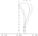
- FIG. 3 is a distortion diagram of a short-distance optical amplifying module according to Embodiment 1 of the present invention.
- FIG. 4 is a field curvature diagram of a short-distance optical amplifying module according to Embodiment 1 of the present invention.
- FIG. 5 is a MTF diagram of a short-distance optical amplifying module according to Embodiment 1 of the present invention.
- FIG. 6 is a schematic structural diagram of a short-distance optical amplifying module according to Embodiment 2 of the present invention.
- FIG. 7 is a distortion diagram of a short-distance optical amplifying module according to Embodiment 2 of the present invention.
- FIG. 8 is a field curvature diagram of a short-distance optical amplifying module according to Embodiment 2 of the present invention.
- FIG. 9 is an MTF diagram of a short-distance optical amplifying module according to Embodiment 3 of the present invention.
- FIG. 10 is a schematic structural diagram of a short-distance optical amplifying module according to Embodiment 3 of the present invention.
- FIG. 11 is a distortion diagram of a short-distance optical amplifying module according to Embodiment 3 of the present invention.
- FIG. 12 is a field curvature diagram of a short-distance optical amplifying module according to Embodiment 3 of the present invention.
- FIG. 13 is a MTF diagram of a short-distance optical amplifying module according to Embodiment 3 of the present invention.
- FIG. 14 is a schematic structural diagram of a short-distance optical amplifying module according to Embodiment 4 of the present invention.
- FIG. 16 is a field curvature diagram of a short-distance optical amplifying module according to Embodiment 4 of the present invention.
- FIG. 17 is a MTF diagram of a short-distance optical amplifying module according to Embodiment 4 of the present invention.
- FIG. 2A, FIG. 2B, FIG. 6, FIG. 10 and FIG. 14 are schematic diagrams showing the structure of a short-distance optical amplifying module according to an embodiment of the present invention.
- the short-distance optical amplifying module comprises a reflective polarizer, a first phase retarder, a third lens 30 and a second phase retarder arranged in sequence, wherein the reflective polarizer, the first phase retarder, and the third lens Any one of the two sides of any one of the 30 and the second phase retarder is further provided with a first lens, and any of the reflective polarizer, the first phase retarder, the third lens 30, and the second phase retarder A second lens is further disposed at any position on both sides of an optical device, wherein the reflective polarizer and the first phase retarder are shown as 50 in FIGS.
- the display screen is 40 and the second phase retarder is not shown.
- the first lens 10, the second lens 20, and the second lens 30 are core components that affect the optical amplification effect, and the system focal length F is formed.
- the first lens 10, the second lens 20, and the third lens 30 may be disposed to be attached to each other at a distance of 10 to 28 mm, or may have a certain pitch.
- the first optical lens E1 in the first lens 10 is adjacent to the first phase retarder, and the second lens 20 is in the second optical surface E2.
- a third optical surface E3 adjacent to the first lens 10 is adjacent to the first lens 10
- a fourth optical surface E4 adjacent to the second phase retarder is adjacent to the second lens 20 in the third lens 30 E5.
- the second phase retarder is adjacent to the second optical retardation sheet E6.
- An optical image on the object side reaches the reflective polarizer via the second phase retarder, the third lens 30, the second lens 20, the first lens 10, and the first phase retarder.
- the first reflection is generated at the reflective polarizer
- the first lens 10, the second lens 20, and the fifth optical surface E5 the sixth optical surface is reached.
- E6 after the second reflection is generated at the sixth optical surface E6, and then sequentially passes through the second lens 20, the first lens 10, the first phase retarder, and the reflective polarizer to enter the human eye. Sight line, such that the optical image can be twice reflected and amplified in the optical amplifying module to achieve the optical magnification requirement.
- the third lens is the main source of the system power.
- the first lens 10 and the second lens 20 are disposed, and the two lenses cooperate with each other to share the focal length of the system and balance each other to improve imaging. quality.
- the third lens The first focal length f 3 (in the third lens, the focal length of the reflective optical surface) satisfies the following conditions:
- F is the focal length of the optical system of the first lens, the second negative lens, and the third lens.
- the incident light is transmitted through the fifth optical surface E5, and the focal length measured by the sixth optical surface E6 is defined as the third lens including the reflective surface focal length f 3 .
- the third lens (the effective focal length including the reflecting surface) is the main source of the system power. If the power is too large, such as close to the total power of the system (f 3 ⁇ F), the aberration is difficult to correct; If the power is too small (f 3 ⁇ 2F), the power of the other lens is too large, and it is necessary to increase the lens to correct the aberration, which is disadvantageous for system miniaturization and weight reduction.
- the power is inversely proportional to the focal length.
- the first focal length f 3 of the third lens satisfies the following conditions:
- the system focal length F formed by the first lens 10, the second negative lens 20, and the third lens 30 is 10 mm to 32 mm, and the three lenses may be disposed to be attached to each other or may have a certain pitch.
- the shape and positional relationship of the three lenses are not limited as long as the system focal length is 10 mm to 32 mm.
- the focal length f 3 of the third lens including the reflecting surface is limited.
- Such a lens is matched with a screen having a screen size of 0.9 to 3 inches, and the entire optical system can be set to obtain a larger The field of view and the allowable large screen resolution, wherein the available field of view V is 90° to 100°, and the allowable screen resolution is 800*800-4000*4000.
- focal length f of the sixth optical surface S6 i.e., focal length f of the semi-transmissive semi-reflective surface S6 of the following:
- F S6 represents the effective focal length reflected by the sixth optical surface
- the reflective surface of the sixth optical surface E6 is the main source of the system power
- the power is too large, such as approaching the total power of the system (f S6 ⁇ F)
- the aberration is difficult to correct; at the same time, the mirror surface is too curved, the lens thickness is large, which will lead to an increase in the thickness of the system, which is not conducive to the requirements of VR wearing equipment.
- the power is too small (f S6 ⁇ 5F)
- the power of the other lens is too large, and it is necessary to increase the lens to correct the aberration, which is disadvantageous for the system miniaturization and weight reduction.
- the focal length f S5 of the fifth optical surface satisfies the following conditions:
- the focal length f S5 is too small, the shape of the third lens 30 is too curved, which is disadvantageous for aberration correction; at the same time, when compared with the second lens 20 and the third lens 10, the surface shape is too curved. Larger, it will lead to an increase in the thickness of the optical system, which is not conducive to the requirements of VR wearable devices.
- the focal length f 2 of the second negative lens satisfies the following conditions:
- the focal length f 2 is too small (
- the shape of the second lens 20 is too curved, and the introduced aberration is large, resulting in an aberration of the entire system;
- the thickness of the second lens 20 is increased, which is disadvantageous for the requirement of slimming and thinning of the VR wearing device.
- the focal length f S3 of the third optical surface satisfies the following conditions based on the optimization objective of achieving miniaturization and weight reduction:
- the second lens 20 is too curved, which is disadvantageous for aberration correction; and is integrated with the first lens 10 and the third lens 30 at the same time. Seeing that the shape of the face is too thick, the thickness of the lens is large, which will lead to an increase in the thickness of the optical system, which is not conducive to the requirement of light and thin VR wearing equipment.
- the focal length f S4 of the fourth optical surface satisfies the following conditions based on the optimization objective of achieving miniaturization and weight reduction:
- the second lens 20 is too curved, which is disadvantageous for aberration correction; and is integrated with the first lens 10 and the third lens 30 at the same time. Seeing that the thickness of the face-type curved lens is too large will lead to an increase in the thickness of the optical system, which is not conducive to the requirement of light and thin VR wearing equipment.
- the focal length f 1 of the first lens satisfies the following conditions:
- the focal length f 1 is too small (
- the face shape of the first lens 10 is too curved, and the introduced aberration is large, resulting in a large difference in the entire system;
- Increasing the thickness of the first lens 10 is not conducive to the requirement of slimming and thinning of the VR wearing device.
- the optical amplifying module has a thickness of 8 mm to 30 mm.
- the image quality of the short-distance optical amplifying module is designed to be 5 mm to 10 mm.
- the adjustable range of the aperture on the object side is designed to be 1.7F to 3.5F, that is, after the first lens,
- the aperture D through which the second lens and the third lens participate in the imaging of the light beam satisfy the following conditions:
- the eye movement range A can be 5 mm to 9 mm.
- the optimized short-range optical amplifying module can be applied to a VR glasses, the glasses further comprising a display screen, and the display screen and the short-distance optical amplification Module coaxial or non-coaxial settings.
- 2A shows the case of coaxial arrangement
- FIG. 2B shows the case of non-coaxial setting, whether or not the coaxial arrangement does not affect the optical magnification effect of the module, the extreme field of view and the eye movement range.
- the optimized short-range optical amplifying module can also be applied to a helmet, the helmet further includes a display screen, and the display screen and the short-distance optical amplification mode Group coaxial or non-coaxial settings.
- the short-distance amplifying module provided by the present invention can also be applied to a VR system, which can include the above-mentioned glasses or helmets, or other wearable devices suitable for user experience.
- the short-distance optical amplifying module of the present embodiment will be further described below in conjunction with the attached table.
- OBJ represents an object in an optical system
- IMA represents an image in an optical system
- STO represents an optical system.
- i denotes the order of the optical surface from the object side (i0)+1
- the first lens 10 on the left side of the light is first directed to the second lens 20 on the right side, and then to the third lens 30.
- MIRROR the reflection goes in the opposite direction
- the reflection to the second MIRROR is reversed again, and then goes from left to right, and finally reaches the image plane.
- the focal length f 3 of the reflective surface of the third lens 30 is designed to be equal to the focal length F of the system.
- the specific design parameters of the first lens 10, the second lens 20 and the third lens 30 are as shown in Table 1:
- the first row OBJ represents the relevant design parameters of the object surface
- the third row STO represents the aperture in the optical system, the aperture is 9 mm
- the fourth row and the fifth row represent the reflective polarization in the optical module a film formed by a sheet and a first phase retarder, the type of the film being a STANDARD standard surface, a material BK7, a diameter of 30.18156 mm, and an aspheric coefficient of 0
- the sixth row and the seventh row respectively representing the first Data corresponding to the first optical surface E1 and the second optical surface E2 of the lens 10, the radius of curvature of the first optical surface E and the second optical surface E2 are both Infinity planes, and the thickness of the first lens 10 is 2 mm ( That is, the pitch from the first optical surface E1 to the second optical surface E2, the thickness value in the sixth line data, the material is H-LAK5A
- the eighth row and the ninth row respectively represent the second lens Data corresponding to the third optical surface E3 of the second optical surface E3
- the tenth row and the eleventh row respectively represent the fifth optical surface E5 of the third lens 30
- the data corresponding to the sixth optical surface E6, the radius of curvature of the fifth optical surface E5 is -68 and -66.19397, respectively, and the thickness of the third lens 30 is 2 mm (ie, from the fifth optical surface E5 to the first
- the distance between the six optical surfaces E6 and the thickness value in the tenth line data) is H-LAK10.
- the twelfth to twenty-fifth rows represent relevant parameters in the reflection and transmission of light between the diaphragm, the first lens 10, the second lens 20, and the third lens 30.
- the twenty-sixth row represents a glass film in the liquid crystal layer of the display screen, the glass film having a thickness of 0.3 mm and a material of BK7.
- the twenty-seventh line IMA represents an image in the optical system.
- the resolution of the viewing angle of the short-distance optical amplifying module can be supported to support a resolution of 400*400, that is, when The three-lens reflective surface has a focal length of 1F, and the f S6 focal length is 1F, which can achieve a large optical amplification effect while maintaining a small overall thickness, so that the module can be applied to a small-sized VR device, and
- the VR device can achieve a better viewing angle of 100°, a large eye movement range of 9mm, high-quality imaging effects, and a screen resolution of 800*800, which gives users a better experience.
- the focal length f 3 of the reflective surface of the third lens 30 is designed to be equal to the system focal length of 1.37F.
- the first row OBJ represents the relevant design parameters of the object surface
- the third row STO represents the aperture in the optical system, the aperture is 9 mm
- the fourth row and the fifth row represent the reflective polarization in the optical module a film formed by a sheet and a first phase retarder, the type of the film being a STANDARD standard surface, a material of BK7, a diameter of 26.09264 mm, and an aspheric coefficient of 0
- the sixth row and the seventh row respectively representing the first
- the data corresponding to the first optical surface E1 and the second optical surface E2 of the lens 10 are respectively Infinity plane and -89.75873, and the thickness of the first lens 10 2 mm (ie, the distance from the first optical surface E1 to the second optical surface E2, the thickness value in the sixth line of data), the material is H-K9L
- the eighth row and the ninth row respectively represent the Data corresponding to the third optical surface E3 of the second lens
- the tenth row and the eleventh row respectively represent data corresponding to the fifth optical surface E5 and the sixth optical surface E6 of the third lens 30, and the radius of curvature of the fifth optical surface E5 is 160.6342 and -54.28037, respectively.
- the thickness of the third lens 30 is 4 mm (that is, the pitch from the fifth optical surface E5 to the sixth optical surface E6, the thickness value in the tenth row data), and the material is D-LAK70.
- the twelfth to twenty-fifth rows represent relevant parameters in the reflection and transmission of light between the diaphragm, the first lens 10, the second lens 20, and the third lens.
- the twenty-sixth row represents a glass film in the liquid crystal layer of the display screen, the glass film having a thickness of 1 mm and a material of BK7.
- the twenty-seventh line IMA represents an image in the optical system.
- the abscissa (space frequency per mm) value of the average ordinate (modulation transfer function) of each field of view is higher than 0.18, and the distortion rate in Fig. 7 is controlled at (-30.5%, 0).
- the resolution of the short-range optical amplifying module can support a resolution of 400*400, that is, It is said that when the focal length of the third lens including the reflecting surface is 1.37F and the focal length of the f S6 is 2F, the larger optical magnification effect can be obtained while keeping the overall thickness small, so that the module can be applied to a small-sized VR device.
- the VR device can achieve a better viewing angle of 96°, a larger eye movement range of 7 mm, and a high-quality imaging effect of 1800*1800, giving the user a better experience.
- the focal length f 3 of the reflective surface of the third lens 30 is designed to be equal to the system focal length of 1.5F.
- the specific design parameters of the first lens 10, the second lens 20 and the third lens 30 are as shown in Table 5:
- the first row OBJ represents the relevant design parameters of the object surface
- the third row STO represents the aperture in the optical system, the aperture is 9 mm
- the fourth row and the fifth row represent the reflective polarization in the optical module a film formed by a sheet and a first phase retarder, the type of the film being a STANDARD standard surface, a material BK7, a diameter of 30.18156 mm, and an aspheric coefficient of 0
- the sixth row and the seventh row respectively representing the first
- the data corresponding to the first optical surface E1 and the second optical surface E2 of the lens 10 are respectively Infinity plane and -126.3604, and the thickness of the first lens 10 4 mm (ie, the distance from the first optical surface E1 to the second optical surface E2, the thickness value in the sixth line of data), the material is H-LAK5A
- the eighth and ninth rows respectively represent the Data corresponding to the third optical surface E3 of the second lens 20 and
- the tenth row and the eleventh row respectively represent data corresponding to the fifth optical surface E5 and the sixth optical surface E6 of the third lens 30, and the radius of curvature of the fifth optical surface E5 is 269.2846 and -101.0977, respectively.
- the thickness of the third lens 30 is 5.5 mm (that is, the pitch from the fifth optical surface E5 to the sixth optical surface E6, the thickness value in the tenth row data), and the material is H-LAK10.
- the twelfth to twenty-fifth rows represent relevant parameters in the reflection and transmission of light between the diaphragm, the first lens 10, the second lens 20, and the third lens.
- the twenty-sixth row represents a glass film in the liquid crystal layer of the display screen, the glass film having a thickness of 0.3 mm and a material of BK7.
- the twenty-seventh line IMA represents an image in the optical system.
- the abscissa (space frequency per mm) value of the average ordinate (modulation transfer function) of each field of view is higher than 0.18, and the distortion rate in Fig. 11 is controlled at (-34%, 0).
- the field curvature control in FIG. 12 is in the range of (-0.2 mm, 0.2 mm), and it is concluded that the resolution of the short-range optical amplifying module can support a resolution of 400*400. That is to say, when the focal length of the third lens including the reflecting surface is 1.5F and the focal length of the f S6 is 2.1F, the larger optical amplification effect can be obtained while keeping the overall thickness small, so that the module can be applied to a small size.
- the VR device can achieve a better viewing angle of 100°, a larger eye movement range of 9 mm, and a high-quality imaging effect of 4000*4000, giving the user a better experience.
- the focal length f 3 of the reflective surface of the third lens 30 is designed to be equal to the focal length 2F of the system.
- the specific design parameters of the first lens 10, the second lens 20 and the third lens 30 are as shown in Table 7:
- the first row OBJ represents the relevant design parameters of the object surface
- the third row STO represents the aperture in the optical system, the aperture is 9 mm
- the fourth row and the fifth row represent the reflective polarization in the optical module a film formed by a sheet and a first phase retarder, the type of the film being a STANDARD standard surface, a material BK7, a diameter of 30.18156 mm, and an aspheric coefficient of 0
- the sixth row and the seventh row respectively representing the first
- the data corresponding to the first optical surface E1 and the second optical surface E2 of the lens 10 are an Infinity plane and -90.62525, respectively, and the thickness of the first lens 10 6 mm (ie, the distance from the first optical surface E1 to the second optical surface E2, the thickness value in the sixth line of data), the material is H-LAK5A
- the eighth and ninth rows respectively represent the Data corresponding to the third optical surface E3 of the second lens 20
- the tenth row and the eleventh row respectively represent data corresponding to the fifth optical surface E5 and the sixth optical surface E6 of the third lens 30, and the radius of curvature of the fifth optical surface E5 is In and 160, respectively.
- the thickness of the third lens 30 is 4 mm (i.e., the pitch from the fifth optical surface E5 to the sixth optical surface E6, the thickness value in the tenth row data), and the material is H-LAK10.
- the twelfth to twenty-fifth rows represent relevant parameters in the reflection and transmission of light between the diaphragm, the first lens 10, the second lens 20, and the third lens.
- the twenty-sixth row represents a glass film in the liquid crystal layer of the display screen, the glass film having a thickness of 0.3 mm and a material of BK7.
- the twenty-seventh line IMA represents an image in the optical system.
- the abscissa (space frequency per mm) value of the average ordinate (modulation transfer function) of each field of view is higher than 0.18, and the distortion rate in Fig. 15 is controlled at (-33.6%, 0).
- the field curvature control in FIG. 16 is in the range of (-2 mm, 2 mm), and it is concluded that the viewing angle resolution of the short-distance optical amplifying module can support a resolution of 400*400.
- the focal length of the third lens including the reflecting surface is 2F and the focal length of the f S6 is 2.67F, the larger optical amplification effect can be obtained while keeping the overall thickness small, so that the module can be applied to a small-sized VR.
- the VR device can achieve a better viewing angle of 100°, a larger eye movement range of 9 mm, and a high-quality imaging effect of 1200*1200, which brings a better experience to the user.
- the focal length of the f S6 may not be set to 2.67F, as long as the focal length of the first lens and/or the second lens is adjusted, f S6 is at 1F-5F.
Landscapes
- Physics & Mathematics (AREA)
- General Physics & Mathematics (AREA)
- Optics & Photonics (AREA)
- Engineering & Computer Science (AREA)
- Theoretical Computer Science (AREA)
- Nonlinear Science (AREA)
- Computer Graphics (AREA)
- Computer Hardware Design (AREA)
- General Engineering & Computer Science (AREA)
- Software Systems (AREA)
- Lenses (AREA)
Abstract
Priority Applications (8)
| Application Number | Priority Date | Filing Date | Title |
|---|---|---|---|
| ES16777519T ES2995758T3 (en) | 2016-03-21 | 2016-03-21 | Short-distance optical magnification module, glasses, helmet and vr system |
| US15/300,391 US10185148B2 (en) | 2016-03-21 | 2016-03-21 | Short-range optical amplification module, spectacles, helmet and VR system |
| PCT/CN2016/076937 WO2017161488A1 (fr) | 2016-03-21 | 2016-03-21 | Module de grossissement optique à courte distance, lunettes, casque et système de réalité virtuelle (vr) |
| PT167775196T PT3249446T (pt) | 2016-03-21 | 2016-03-21 | Módulo de ampliação ótica a curta distância, óculos, capacete e sistema de realidade virtual (vr) |
| FIEP16777519.6T FI3249446T3 (fi) | 2016-03-21 | 2016-03-21 | Lyhyen kantaman optinen vahvistusmoduuli, lasit, kypärä ja vr-järjestelmä |
| KR1020187030469A KR102254565B1 (ko) | 2016-03-21 | 2016-03-21 | 근거리 광 증폭 모듈, 안경, 헬멧 및 vr 시스템 |
| JP2016563161A JP6441383B2 (ja) | 2016-03-21 | 2016-03-21 | 短距離光増幅モジュール、眼鏡、ヘルメット、および、vrシステム |
| EP16777519.6A EP3249446B1 (fr) | 2016-03-21 | 2016-03-21 | Module de grossissement optique à courte distance, lunettes, casque et système de réalité virtuelle (vr) |
Applications Claiming Priority (1)
| Application Number | Priority Date | Filing Date | Title |
|---|---|---|---|
| PCT/CN2016/076937 WO2017161488A1 (fr) | 2016-03-21 | 2016-03-21 | Module de grossissement optique à courte distance, lunettes, casque et système de réalité virtuelle (vr) |
Publications (1)
| Publication Number | Publication Date |
|---|---|
| WO2017161488A1 true WO2017161488A1 (fr) | 2017-09-28 |
Family
ID=59900912
Family Applications (1)
| Application Number | Title | Priority Date | Filing Date |
|---|---|---|---|
| PCT/CN2016/076937 Ceased WO2017161488A1 (fr) | 2016-03-21 | 2016-03-21 | Module de grossissement optique à courte distance, lunettes, casque et système de réalité virtuelle (vr) |
Country Status (8)
| Country | Link |
|---|---|
| US (1) | US10185148B2 (fr) |
| EP (1) | EP3249446B1 (fr) |
| JP (1) | JP6441383B2 (fr) |
| KR (1) | KR102254565B1 (fr) |
| ES (1) | ES2995758T3 (fr) |
| FI (1) | FI3249446T3 (fr) |
| PT (1) | PT3249446T (fr) |
| WO (1) | WO2017161488A1 (fr) |
Cited By (3)
| Publication number | Priority date | Publication date | Assignee | Title |
|---|---|---|---|---|
| CN112558287A (zh) * | 2020-12-30 | 2021-03-26 | 深圳纳德光学有限公司 | 一种折反射式目镜光学系统及头戴显示装置 |
| CN114415381A (zh) * | 2022-03-30 | 2022-04-29 | 南昌龙旗信息技术有限公司 | 光学成像模组及虚拟现实设备 |
| CN117631285A (zh) * | 2022-08-19 | 2024-03-01 | 大根光学工业股份有限公司 | 光学系统与头戴装置 |
Families Citing this family (12)
| Publication number | Priority date | Publication date | Assignee | Title |
|---|---|---|---|---|
| US10324292B2 (en) * | 2016-03-21 | 2019-06-18 | Shenzhen Dlodlo New Technology Co., Ltd. | Short range optical amplification module, spectacles, helmet and VR system |
| CN207181829U (zh) * | 2017-09-25 | 2018-04-03 | 京东方科技集团股份有限公司 | 虚拟现实头盔 |
| EP3874303A4 (fr) * | 2018-11-02 | 2022-12-28 | Gary Sharp Innovations, Inc. | Architectures optiques multipassages compactes reposant sur une polarisation |
| CN114280783B (zh) * | 2021-12-22 | 2022-12-06 | 上海摩软通讯技术有限公司 | 光学模组及vr设备 |
| TWI844025B (zh) | 2022-05-27 | 2024-06-01 | 大立光電股份有限公司 | 光學系統與頭戴裝置 |
| CN115079331A (zh) * | 2022-07-26 | 2022-09-20 | 歌尔光学科技有限公司 | 一种光学模组以及头戴显示设备 |
| CN114942489A (zh) * | 2022-07-26 | 2022-08-26 | 歌尔光学科技有限公司 | 一种光学模组以及头戴显示设备 |
| TWI838140B (zh) * | 2023-02-24 | 2024-04-01 | 新鉅科技股份有限公司 | 光學透鏡組及頭戴式電子裝置 |
| CN116400481A (zh) * | 2023-04-10 | 2023-07-07 | 常州市瑞泰光电有限公司 | 光学模组及vr设备 |
| TWI856640B (zh) * | 2023-05-04 | 2024-09-21 | 新鉅科技股份有限公司 | 光學透鏡組和頭戴式電子裝置 |
| TWI852539B (zh) * | 2023-05-08 | 2024-08-11 | 新鉅科技股份有限公司 | 光學透鏡組和頭戴式電子裝置 |
| CN121889717A (zh) * | 2023-09-19 | 2026-04-17 | 3M创新有限公司 | 折叠式光学透镜组件和光学系统 |
Citations (5)
| Publication number | Priority date | Publication date | Assignee | Title |
|---|---|---|---|---|
| EP0718645A2 (fr) * | 1994-12-19 | 1996-06-26 | Sharp Kabushiki Kaisha | Système optique et afficheur monté sur tête utilisant ledit système optique |
| CN1930511A (zh) * | 2003-11-26 | 2007-03-14 | 吕勒公司 | 用于真实世界模拟的改进的准直光学元件 |
| CN104414747A (zh) * | 2013-09-11 | 2015-03-18 | 财团法人工业技术研究院 | 虚像显示装置 |
| CN105093555A (zh) * | 2015-07-13 | 2015-11-25 | 深圳多新哆技术有限责任公司 | 短距离光学放大模组及使用其的近眼显示光学模组 |
| CN205562977U (zh) * | 2016-03-21 | 2016-09-07 | 深圳多哚新技术有限责任公司 | 短距离光学放大模组、眼镜、头盔及vr系统 |
Family Cites Families (17)
| Publication number | Priority date | Publication date | Assignee | Title |
|---|---|---|---|---|
| US3480875A (en) * | 1965-12-06 | 1969-11-25 | Ibm | Laser scanning device having two lens systems with a common focal plane |
| US6767594B1 (en) * | 1997-12-16 | 2004-07-27 | Gosudarstvenny Nauchny Tsentr Rossiiskoi | Polarizer and liquid crystal display element |
| US6208463B1 (en) * | 1998-05-14 | 2001-03-27 | Moxtek | Polarizer apparatus for producing a generally polarized beam of light |
| US6108131A (en) * | 1998-05-14 | 2000-08-22 | Moxtek | Polarizer apparatus for producing a generally polarized beam of light |
| US6271969B1 (en) * | 1998-12-11 | 2001-08-07 | Agilent Technolgoies, Inc. | Folded optical system having improved image isolation |
| US6075651A (en) | 1999-01-28 | 2000-06-13 | Kaiser Electro-Optics, Inc. | Compact collimating apparatus |
| JP2003529795A (ja) * | 2000-03-31 | 2003-10-07 | コーニンクレッカ フィリップス エレクトロニクス エヌ ヴィ | ヘッドマウントディスプレイ |
| EP1277073B1 (fr) * | 2000-04-25 | 2006-11-15 | ASML Holding N.V. | Systeme de reduction optique avec commande de polarisation d'eclairage |
| JP2005148655A (ja) * | 2003-11-19 | 2005-06-09 | Sony Corp | 画像表示装置 |
| US20090052838A1 (en) * | 2004-03-22 | 2009-02-26 | Mcdowall Ian | Electrically controlled optical elements and method |
| MX2009012113A (es) * | 2007-05-09 | 2010-03-15 | Real D | Sistema de conversion de polarizacion y método para proyección estereoscópica. |
| US8425041B2 (en) * | 2008-12-01 | 2013-04-23 | Reald Inc. | Stereoscopic projection systems for employing spatial multiplexing at an intermediate image plane |
| EP2449419B1 (fr) * | 2009-06-29 | 2017-09-20 | RealD Inc. | Système de projection stéréoscopique employant un multiplexage spatial au niveau d'un plan d'image intermédiaire |
| US9933627B2 (en) | 2013-02-25 | 2018-04-03 | Nikon Corporation | Optical system, optical member, micromirror array, display device, and image- capturing device |
| KR102257641B1 (ko) * | 2016-03-21 | 2021-06-01 | 쉔젠 들로들로 뉴 테크놀로지 컴퍼니 리미티드 | 근거리 광 증폭 모듈, 안경, 헬멧 및 가상현실 시스템 |
| US10324292B2 (en) * | 2016-03-21 | 2019-06-18 | Shenzhen Dlodlo New Technology Co., Ltd. | Short range optical amplification module, spectacles, helmet and VR system |
| EP3260908B8 (fr) * | 2016-03-21 | 2021-08-04 | Shenzhen Dlodlo New Technology Co., Ltd. | Module de grossissement optique à courte distance, lunettes, casque et système de réalité virtuelle (vr) |
-
2016
- 2016-03-21 FI FIEP16777519.6T patent/FI3249446T3/fi active
- 2016-03-21 JP JP2016563161A patent/JP6441383B2/ja active Active
- 2016-03-21 WO PCT/CN2016/076937 patent/WO2017161488A1/fr not_active Ceased
- 2016-03-21 PT PT167775196T patent/PT3249446T/pt unknown
- 2016-03-21 KR KR1020187030469A patent/KR102254565B1/ko active Active
- 2016-03-21 US US15/300,391 patent/US10185148B2/en active Active
- 2016-03-21 EP EP16777519.6A patent/EP3249446B1/fr active Active
- 2016-03-21 ES ES16777519T patent/ES2995758T3/es active Active
Patent Citations (5)
| Publication number | Priority date | Publication date | Assignee | Title |
|---|---|---|---|---|
| EP0718645A2 (fr) * | 1994-12-19 | 1996-06-26 | Sharp Kabushiki Kaisha | Système optique et afficheur monté sur tête utilisant ledit système optique |
| CN1930511A (zh) * | 2003-11-26 | 2007-03-14 | 吕勒公司 | 用于真实世界模拟的改进的准直光学元件 |
| CN104414747A (zh) * | 2013-09-11 | 2015-03-18 | 财团法人工业技术研究院 | 虚像显示装置 |
| CN105093555A (zh) * | 2015-07-13 | 2015-11-25 | 深圳多新哆技术有限责任公司 | 短距离光学放大模组及使用其的近眼显示光学模组 |
| CN205562977U (zh) * | 2016-03-21 | 2016-09-07 | 深圳多哚新技术有限责任公司 | 短距离光学放大模组、眼镜、头盔及vr系统 |
Non-Patent Citations (1)
| Title |
|---|
| See also references of EP3249446A4 * |
Cited By (5)
| Publication number | Priority date | Publication date | Assignee | Title |
|---|---|---|---|---|
| CN112558287A (zh) * | 2020-12-30 | 2021-03-26 | 深圳纳德光学有限公司 | 一种折反射式目镜光学系统及头戴显示装置 |
| CN112558287B (zh) * | 2020-12-30 | 2024-06-04 | 深圳纳德光学有限公司 | 一种折反射式目镜光学系统及头戴显示装置 |
| CN114415381A (zh) * | 2022-03-30 | 2022-04-29 | 南昌龙旗信息技术有限公司 | 光学成像模组及虚拟现实设备 |
| CN114415381B (zh) * | 2022-03-30 | 2022-07-22 | 南昌龙旗信息技术有限公司 | 光学成像模组及虚拟现实设备 |
| CN117631285A (zh) * | 2022-08-19 | 2024-03-01 | 大根光学工业股份有限公司 | 光学系统与头戴装置 |
Also Published As
| Publication number | Publication date |
|---|---|
| US20180088333A1 (en) | 2018-03-29 |
| PT3249446T (pt) | 2024-11-28 |
| KR20180129846A (ko) | 2018-12-05 |
| JP2018513393A (ja) | 2018-05-24 |
| EP3249446B1 (fr) | 2024-09-18 |
| EP3249446A4 (fr) | 2018-04-25 |
| JP6441383B2 (ja) | 2018-12-19 |
| KR102254565B1 (ko) | 2021-05-21 |
| ES2995758T3 (en) | 2025-02-11 |
| FI3249446T3 (fi) | 2024-11-19 |
| US10185148B2 (en) | 2019-01-22 |
| EP3249446A1 (fr) | 2017-11-29 |
Similar Documents
| Publication | Publication Date | Title |
|---|---|---|
| WO2017161488A1 (fr) | Module de grossissement optique à courte distance, lunettes, casque et système de réalité virtuelle (vr) | |
| CN205562977U (zh) | 短距离光学放大模组、眼镜、头盔及vr系统 | |
| CN107219637B (zh) | 短距离光学放大模组、眼镜、头盔及vr系统 | |
| KR102162951B1 (ko) | 근거리 광 증폭 모듈, 안경, 헬멧 및 vr 시스템 | |
| KR102257641B1 (ko) | 근거리 광 증폭 모듈, 안경, 헬멧 및 가상현실 시스템 | |
| WO2017161486A1 (fr) | Module de grossissement optique à courte distance, lunettes, casque et système de réalité virtuelle (vr) | |
| CN105629494B (zh) | 一种短距离光学放大模组、眼镜、头盔以及vr系统 | |
| CN105676477B (zh) | 短距离光学放大模组、眼镜、头盔及vr系统 | |
| CN213690113U (zh) | 成像结构和头戴显示设备 | |
| CN205562978U (zh) | 短距离光学放大模组、眼镜、头盔及vr系统 | |
| CN105652460B (zh) | 短距离光学放大模组、眼镜、头盔及vr系统 | |
| CN205562979U (zh) | 短距离光学放大模组、眼镜、头盔及vr系统 | |
| CN205562976U (zh) | 一种短距离光学放大模组、眼镜、头盔以及vr系统 | |
| CN213934432U (zh) | 光学模组及vr设备 | |
| CN113325565B (zh) | 一种反射式目镜光学系统及头戴近眼显示装置 | |
| CN114624879B (zh) | 头戴型显示器的光学系统 | |
| CN113341557A (zh) | 一种反射式目镜光学系统及头戴近眼显示装置 | |
| CN113325566B (zh) | 一种反射式目镜光学系统及头戴近眼显示装置 | |
| CN113341559A (zh) | 一种反射式目镜光学系统及头戴近眼显示装置 |
Legal Events
| Date | Code | Title | Description |
|---|---|---|---|
| WWE | Wipo information: entry into national phase |
Ref document number: 15300391 Country of ref document: US |
|
| ENP | Entry into the national phase |
Ref document number: 2016563161 Country of ref document: JP Kind code of ref document: A |
|
| REEP | Request for entry into the european phase |
Ref document number: 2016777519 Country of ref document: EP |
|
| WWE | Wipo information: entry into national phase |
Ref document number: 2016777519 Country of ref document: EP |
|
| NENP | Non-entry into the national phase |
Ref country code: DE |
|
| ENP | Entry into the national phase |
Ref document number: 20187030469 Country of ref document: KR Kind code of ref document: A |