WO2017163276A1 - Station de base radio, système de radiocommunication, et procédé de planification de radiocommunication - Google Patents
Station de base radio, système de radiocommunication, et procédé de planification de radiocommunication Download PDFInfo
- Publication number
- WO2017163276A1 WO2017163276A1 PCT/JP2016/001725 JP2016001725W WO2017163276A1 WO 2017163276 A1 WO2017163276 A1 WO 2017163276A1 JP 2016001725 W JP2016001725 W JP 2016001725W WO 2017163276 A1 WO2017163276 A1 WO 2017163276A1
- Authority
- WO
- WIPO (PCT)
- Prior art keywords
- radio
- wireless
- terminals
- base station
- predetermined value
- Prior art date
- Legal status (The legal status is an assumption and is not a legal conclusion. Google has not performed a legal analysis and makes no representation as to the accuracy of the status listed.)
- Ceased
Links
Images





Classifications
-
- H—ELECTRICITY
- H04—ELECTRIC COMMUNICATION TECHNIQUE
- H04W—WIRELESS COMMUNICATION NETWORKS
- H04W16/00—Network planning, e.g. coverage or traffic planning tools; Network deployment, e.g. resource partitioning or cells structures
- H04W16/24—Cell structures
- H04W16/28—Cell structures using beam steering
-
- H—ELECTRICITY
- H04—ELECTRIC COMMUNICATION TECHNIQUE
- H04W—WIRELESS COMMUNICATION NETWORKS
- H04W72/00—Local resource management
- H04W72/04—Wireless resource allocation
Definitions
- the present invention relates to a radio base station, a radio communication system, and a radio communication scheduling method.
- next-generation wireless communication technologies have been discussed in order to further increase the speed and capacity of wireless communication in wireless communication systems such as cellular phone systems (cellular systems).
- 3GPP 3rd Generation Partnership Project
- LTE Long Term Evolution
- LTE-A LTE-Advanced
- the disclosed technology has been made in view of the above, and provides a radio base station, a radio communication system, and a radio communication scheduling method capable of efficiently allocating radio resources to a large number of radio terminals. With the goal.
- the disclosed radio base station has a difference between directions of a plurality of radio terminals from the radio base station in a first case where the difference is equal to or greater than a first predetermined value.
- Radio communication using multi-user MIMO is performed for a plurality of radio terminals, and a difference in direction from the radio base station of the plurality of radio terminals is less than the first predetermined value,
- a second case in which the distance between the wireless terminals is equal to or greater than a second predetermined value and the wireless terminal closer to the wireless base station is equipped with a successive interference canceller, and the wireless base stations of the wireless terminals
- a difference in direction from the first predetermined value is less than the first predetermined value, a distance between the plurality of wireless terminals is less than the second predetermined value, and at least one of the plurality of wireless terminals is a successive interference canceller.
- a control unit configured to perform wireless communication using different time-frequency resources for the terminal, and in the fourth case, the control unit has a relative speed of the plurality of wireless terminals equal to or greater than a third predetermined value; In some cases, wireless communication using multi-user MIMO is performed on the plurality of wireless terminals without performing wireless communication using different time-frequency resources.
- wireless base station the wireless communication system, and the wireless communication scheduling method disclosed in this case, there is an effect that wireless resources can be efficiently allocated to a large number of wireless terminals.
- FIG. 1A and 1B are diagrams for explaining the technical significance of the first embodiment.
- FIG. 2 is a diagram illustrating a processing flow of the radio base station according to the third embodiment.
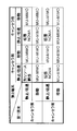
- FIG. 3 is a diagram illustrating a first table regarding scheduling by the radio base station according to the third embodiment.
- FIG. 4 is a diagram illustrating a second table regarding scheduling by the radio base station according to the third embodiment.
- FIG. 5 is a diagram illustrating an example of a table defining wireless terminal category information.
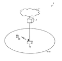
- FIG. 6 is a diagram illustrating an example of a network configuration of the wireless communication system according to each embodiment.
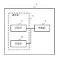
- FIG. 7 is an example of a functional configuration diagram of a radio base station in the radio communication system of each embodiment.
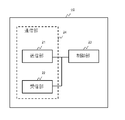
- FIG. 8 is an example of a functional configuration diagram of a wireless terminal in the wireless communication system of each embodiment.
- FIG. 9 is an example of a hardware configuration diagram of a radio base station in the radio communication system of each embodiment.
- FIG. 10 is an example of a hardware configuration diagram of a wireless terminal in the wireless communication system of each embodiment.
- radio resources including time and frequency are limited, it can be easily imagined that when radio resources are individually allocated to a large number of radio terminals, the radio resources are exhausted. For this reason, it is considered important that the radio base station allocates the same radio resource to a plurality of radio terminals so that the radio resource is efficiently used and exhaustion is avoided.
- the same radio resource assigned to a plurality of radio terminals refers to radio resources having the same time and frequency unless otherwise specified.
- the same resource block corresponding to the same frequency
- the same subframe corresponding to the same time
- MU-MIMO Multi User-Multi Input Multi Output: Multiuser MIMO
- NOMA Non-Orthogonal Multiple Access: Non-orthogonal multiple access
- MU-MIMO is an extension of conventional MIMO (Multi-Input Multi-Output).
- Conventional MIMO is applied between one radio base station and one radio terminal, whereas MU-MIMO is 1 It is applied between one radio base station and a plurality of radio terminals.
- MU-MIMO a plurality of radio communications for a radio base station and a plurality of radio terminals are spatially separated and so-called spatial multiplexing is performed.
- the radio base station performs directional radio communication using the same radio resource for each of a plurality of radio terminals having different directions. By this directivity, interference between a plurality of radio communications based on the same radio resource is suppressed, and so-called spatial multiplexing is realized.
- MU-MIMO in order to realize MU-MIMO, it is necessary in principle that the directions of a plurality of wireless terminals from the wireless base station are sufficiently separated.
- the directions of multiple wireless terminals are the same or close, even if wireless communication is performed from the wireless base station to each wireless terminal using the same wireless resource, they interfere with each other and cannot correctly decode data on the wireless terminal side Because.
- MI-MIMO a plurality of antennas are required on the radio base station side, but a single antenna may be used on the radio terminal side. Therefore, MU-MIMO has an advantage that it can be easily applied to a wireless terminal having a relatively low performance such as a sensor device.
- MU-MIMO has the advantage that the processing load on the wireless terminal side is relatively small and the power consumption is relatively small because no special processing is required on the wireless terminal side.
- NOMA multiplexes multiple wireless terminals non-orthogonally in the power axis direction.
- NOMA is applied to a plurality of wireless terminals having different distances from a wireless base station.
- wireless communication is performed with a difference in transmission power, using the same wireless resource, to a plurality of wireless terminals having different distances from the wireless base station. That is, the radio base station transmits a radio signal to which a large transmission power is allocated to a radio terminal (cell edge radio terminal) far from the radio base station using the same radio resource, and a radio signal close to the radio base station.
- the terminal nearby wireless terminal transmits a radio signal to which a small transmission power is assigned.
- the radio signal addressed to the nearby radio terminal becomes an interference signal.
- the radio signal addressed to the nearby radio terminal is assumed to have weak transmission power, the interference signal reaching the cell edge radio terminal is Relatively very small. Therefore, the cell edge radio terminal can correctly decode the radio signal addressed to itself.
- the nearby radio terminal the radio signal addressed to the cell edge radio terminal becomes an interference signal, but the radio signal addressed to the cell edge radio terminal has a relatively strong transmission power. Is very large. Therefore, the neighboring wireless terminal first decodes the signal for the cell edge wireless terminal (that is, the interference signal), and then uses the decoding result to separate the signal for the neighboring wireless terminal. Therefore, even in the nearby wireless terminal, the wireless signal addressed to itself can be correctly decoded.
- Such stepwise interference cancellation processing is called Successive Interference Cancellation (SIC: Sequential Interference Cancellation), and the hardware or function for performing SIC is called a successive interference canceller. Since the successive interference canceller is required to have high processing performance, it has been difficult to realize in the past. However, with the recent improvement in performance of wireless terminals, there is a possibility of practical use particularly in high-performance wireless terminals. However, compared to MU-MIMO, which does not require special processing on the wireless terminal side, NOMA also has a relatively large processing load on the wireless terminal side and relatively large power consumption.
- NOMA is a technology that is inherently applied to a plurality of wireless terminals with different distances from a wireless base station, but the same technology is applied to wireless terminals with the same or close distance from the wireless base station. It is also possible in principle to apply to this.
- the transmission power corresponding to the distance from the radio base station is assigned to the radio terminal that performs SIC, and the transmission power that is larger than the distance from the radio base station is allocated to the radio terminal that does not perform SIC.
- any wireless terminal can correctly decode a signal addressed to itself based on the same principle as NOMA.
- such a technique may be referred to as an extended NOMA for convenience.
- the extended NOMA When applying the extended NOMA, since excessive transmission power is allocated to a wireless terminal that does not perform SIC, the communication efficiency from the viewpoint of transmission power decreases. However, according to the extended NOMA, since the same radio resource can be allocated to a plurality of radio terminals, it is considered effective from the viewpoint of radio resource utilization efficiency.
- NOMA is a concept including extended NOMA unless otherwise specified. That is, NOMA in the present application is a concept including original NOMA and extended NOMA.
- MU-MIMO and NOMA original NOMA or extended NOMA
- NOMA original NOMA or extended NOMA
- MU-MIMO consumes less power, so when radio base stations schedule radio resources, MU-MIMO priority should be set relatively high it is conceivable that.
- MU-MIMO requires a condition that directions from a radio base station of a plurality of radio terminals are different.
- the original NOMA can be applied if the distance between multiple wireless terminals is long, and the extended NOMA can be applied if the distance is short.
- the condition that a nearby wireless terminal can perform SIC that is, relatively high performance
- NOMA at least one of multiple wireless terminals that are close to each other can perform SIC. Conditions are needed. Therefore, NOMA cannot cover all cases where MU-MIMO cannot be applied.
- MU-MIMO should be preferentially applied from the viewpoint of power consumption.
- MU-MIMO requires a condition that directions from a radio base station of a plurality of radio terminals are different, there are not a few scenes that cannot be applied, and it is desirable that this point be improved.
- the inventor of the present invention has come up with the present invention by examining the problems of the comparative examples described above.
- the first embodiment is a radio base station, and in the first case where the difference in direction from a plurality of radio terminals from the radio base station is equal to or greater than a first predetermined value, Wireless communication is performed using user MIMO, a difference in direction of the plurality of wireless terminals from the wireless base station is less than the first predetermined value, and a distance between the plurality of wireless terminals is a second predetermined value.
- the difference between the second case in which the one closer to the radio base station of the plurality of radio terminals includes a successive interference canceller and the difference in direction from the radio base station of the plurality of radio terminals A third case in which the distance between the plurality of wireless terminals is less than the second predetermined value, and at least one of the plurality of wireless terminals includes a successive interference canceller; In either case, N for the plurality of wireless terminals In a fourth case in which MA is applied and wireless communication is performed and none of the first case, the second case, and the third case is performed, different time-frequency resources are assigned to the plurality of wireless terminals.
- a control unit that performs the used wireless communication and in the fourth case, the control unit, when the relative speed of the plurality of wireless terminals is equal to or greater than a third predetermined value, On the other hand, it is based on a radio base station that performs radio communication using multiuser MIMO without performing radio communication using different time-frequency resources.
- the direction of two radio terminals from the radio base station is close, one is located in the vicinity of the radio base station and the other is located at the cell edge, and the neighboring radio terminal performs SIC
- the difference between the directions of the two wireless terminals from the wireless base station is less than the first predetermined value, and the distance between the two wireless terminals is greater than or equal to the second predetermined value,
- the one closer to the wireless base station is not equipped with a successive interference canceller.
- FIG. 1A is a diagram showing such a situation.
- the radio base station 10 is going to perform radio communication with two radio terminals 20 that are close to each other from the radio base station.
- the two wireless terminals 20 include a nearby wireless terminal 20a closer to the wireless base station 10 and a cell edge wireless terminal 20b farther away.
- FIG. 1B illustrates such a situation.
- the functions of the two radio terminals 20 from the radio base station 10 are close, one is located in the vicinity and the other is located at the cell edge, and the neighboring radio terminal 20a performs SIC.
- the two wireless terminals 20 are close to each other from the wireless base station 10, the two wireless terminals 20 are also close to each other from the wireless base station 10, and at least one of the wireless terminals 20 is connected to the wireless base station 10. The same can be said in a situation where the terminal 20 has a function of performing SIC.
- the magnitude of the relative speed of the two wireless terminals 20 is small. If it is equal to or greater than the predetermined value, in other words, when at least one of the two wireless terminals 20 is moving, MU-MIMO is applied to the two wireless terminals 20. As a result, in the comparative example described above, MU-MIMO can be applied in the first embodiment in some cases where neither MU-MIMO nor NOMA can be applied.
- the second embodiment is the radio base station 10 of the first embodiment, and in the second case or the third case, the control unit further determines the relative speed of the plurality of radio terminals 20. Is greater than or equal to the third predetermined value, based on the radio base station 10 that performs radio communication applying multi-user MIMO without performing radio communication applying NOMA to the plurality of radio terminals 20.
- NOMA original NOMA or extended NOMA
- the directions of the two radio terminals 20 from the radio base station 10 are close, one is located in the vicinity and the other is located at the cell edge, and the neighboring radio terminal 20a performs SIC
- MU-MIMO cannot be applied at that time, and NOMA must be applied.
- NOMA must be applied.
- the directions of the two radio terminals 20 from the radio base station 10 may be shifted, and MU-MIMO may be applicable. . That is, even if MU-MIMO cannot be applied at a certain point in time, MU-MIMO may be applicable (after a relatively short time).
- the directions of the two radio terminals 20 from the radio base station 10 are close, the positions of the two radio terminals 20 from the radio base station 10 are also close, and at least one radio terminal 20 performs SIC.
- the magnitude of the relative speed of the two wireless terminals 20 is equal to or greater than a predetermined value.
- MU-MIMO is applied to the two wireless terminals 20.
- MU-MIMO has an advantage that power consumption on the wireless terminal 20 side is small compared to NOMA. Therefore, according to the second embodiment, there is a remarkable effect that the power consumption of the wireless terminal 20 can be reduced as compared with the comparative example described above.
- FIG. 2 is a diagram illustrating a processing flow of the radio base station 10 according to the third embodiment.
- This processing flow assumes a case where the radio base station 10 performs scheduling for two specific radio terminals 20 (scheduling targets), that is, radio resource allocation.
- the radio base station 10 can select two specific units from all the subordinate radio terminals 20 in each transmission time interval (TTI) and execute the process flow of FIG. 2 (that is, the process flow of FIG. 2 is This is performed for each combination of two specific wireless terminals 20).
- TTI corresponds to a subframe (1 millisecond).
- the radio base station 10 acquires information about the radio terminal 20 (hereinafter referred to as terminal information) for each specific two radio terminals 20 in S101.
- the terminal information includes at least information about the direction of the radio terminal 20 from the radio base station 10 (hereinafter referred to as direction information) and information about the distance of the radio terminal 20 from the radio base station 10 (hereinafter distance information). ), Information on the presence / absence of the canceller in the wireless terminal 20 (hereinafter referred to as canceller information), and information on the moving speed of the wireless terminal 20 (hereinafter referred to as speed information).
- the direction information is information regarding the distance of the wireless terminal 20 from the wireless base station 10.
- the direction information may be information itself indicating the direction of the radio terminal 20 from the radio base station 10, or information for estimating the direction of the radio terminal 20 from the radio base station 10 (information for estimating the direction). ).
- various information can be used as shown below. That is, the radio base station 10 can obtain direction information by various means.
- the radio base station 10 determines the direction of the radio terminal 20 based on the feedback signal. Can be estimated.
- this feedback signal for example, PMI (Precoding Matrix Indicator) in LTE can be used.
- the radio base station 10 may estimate the direction of the radio terminal 20 by measuring the uplink reference signal (uplink pilot signal) transmitted from each radio terminal 20 (in this case, however, Note that the wireless communication system needs to employ TDD (Time Division Division Duplex) from the viewpoint of the symmetry of the communication path).
- the wireless terminal 20 includes a GPS (Global Positioning System) or the like, the wireless base station 10 can also estimate the direction (position) of the wireless terminal 20 based on the positioning information.
- the distance information is information related to the distance of the wireless terminal 20 from the wireless base station 10.
- the distance information may be information indicating the distance from the radio base station 10 of the radio terminal 20 or information for estimating the distance of the radio terminal 20 from the radio base station 10 (information that can estimate the distance). ).
- various information can be used as shown below. In other words, the radio base station 10 can acquire the distance information by various means.
- the radio base station 10 determines the distance of the radio terminal 20 based on the feedback signal. Can be estimated. As this feedback signal, for example, a measurement report in LTE can be used. Further, the radio base station 10 may estimate the direction of the radio terminal 20 by the radio base station 10 measuring the reception power of the uplink signal transmitted from each radio terminal 20. Further, when the wireless terminal 20 includes a GPS (Global Positioning System) or the like, the wireless base station 10 can also estimate the distance (position) of the wireless terminal 20 from the base station based on the positioning information. .
- GPS Global Positioning System
- Canceller information is information indicating whether or not the wireless terminal 20 has a successive interference canceller (whether or not the wireless terminal 20 has a function (capability) to perform SIC).
- the radio base station 10 can acquire the canceller information by, for example, some uplink control message from the radio terminal 20. Further, the radio base station 10 receives, for example, a control message indicating whether the radio terminal 20 is a machine type or a normal type (other than the machine type) from each radio terminal 20, and when the radio terminal 20 is a machine type, the radio terminal 20 May be regarded as having no canceller.
- an RRCConnectionRequest message that is a connection request from the radio terminal 20 to the radio base station 10
- an RRCConnectionSetupComplete message that is a connection setup completion notification
- the radio terminal 20 to the radio base station 10 are radio terminals.
- a UECapabilityInformation message for notifying 20 capabilities can be used.
- canceller information and the identifier of the radio terminal 20 are stored in association with each other, and the radio base station 10 inquires about the canceller information based on the identifier of the radio terminal 20 as necessary. It is also possible.
- IMSI International Mobile Subscriber Identity
- TMSI Temporary Mobile Subscriber Identity
- C-RANTI Cell Radio Network Temporary Identifier
- Speed information is information regarding the moving speed of the wireless terminal 20.
- the speed information may be information indicating the moving speed of the radio terminal 20, or information for estimating the moving speed of the radio terminal 20 (information that can estimate the moving speed).
- speed information various information can be used as shown below. In other words, the radio base station 10 can acquire speed information by various means.
- the radio base station 10 can acquire speed information by receiving from each radio terminal 20 a control message indicating whether it is a fixed radio terminal 20 or a mobile radio terminal 20.
- the wireless terminal 20 needs to recognize whether it is the mobile wireless terminal 20 or the fixed wireless terminal 20, but this may be stored in advance as information by the wireless terminal 20, or the wireless terminal 20. However, it may be determined based on an actual speed estimated based on an inertial sensor or GPS.
- the radio base station 10 receives, for example, a control message indicating whether the radio terminal 20 is a machine type or a normal type (other than a machine type) from each radio terminal 20, and when the radio terminal 20 is a normal type, the radio terminal 20 May be considered as moving.
- the radio base station 10 may receive a control message indicating the actual speed itself estimated by the radio terminal 20 based on an inertial sensor or GPS from the radio terminal 20.
- the above-described RRCConnectionRequest message, RRCConnectionSetupComplete message, UECapabilityInformation message, or the like can be used as a control message for notifying speed information from the radio terminal 20 to the radio base station 10, and PUCCH (Physical Uplink) It is also possible to use an uplink control signal on (Control Channel: physical uplink control channel).
- the radio base station 10 acquires each terminal information (direction information, distance information, canceller information, speed information), but even if these are acquired collectively (in one message or signal). It may be obtained at different timings (in different messages or signals). These messages or signals may be transmitted spontaneously by the wireless terminal 20 or may be transmitted by the wireless terminal 20 in response to a request signal from the wireless base station 10.
- the wireless terminal 20 when transmitting the terminal information, the wireless terminal 20 also transmits the identifier of the wireless terminal 20 itself to the wireless base station 10.
- the radio base station 10 can handle each radio terminal 20 in association with each terminal information corresponding thereto.
- an identifier of the radio terminal 20 for example, IMSI, TMSI, C-RANTI, etc. described above can be used.
- step S102 the radio base station 10 determines whether or not the directions of the specific two radio terminals 20 from the radio base station 10 are sufficiently separated (whether the direction is far). This determination is performed based on the direction information acquired by the radio base station 10 in S101. At this time, the radio base station 10 determines whether or not the difference between the directions (estimated values) of the two radio terminals 20 is less than the first predetermined value, thereby sufficiently separating the directions of the two radio terminals 20. It can be determined whether or not.
- the direction of the wireless terminal 20 may be one-dimensional, or may be determined in two dimensions, for example, a horizontal direction and a vertical direction.
- the radio base station 10 determines to apply MU-MIMO to the two radio terminals 20 that have been determined in S102 if the direction from the radio base station 10 is sufficiently far away. . Since these radio terminals 20 are far away from the radio base station 10, MU-MIMO with high priority can be applied among the means for allocating the same radio resources to a plurality of radio terminals 20 (because of low power consumption). That's why.
- the radio base station 10 has two radio terminals for the two radio terminals 20 that have been determined in S102 that the direction from the radio base station 10 is not sufficiently separated. It is determined whether the distance between 20 is sufficiently large (whether the distance is far). This determination is performed based on the distance information acquired by the radio base station 10 in S101. At this time, the radio base station 10 determines whether or not the distance between the two radio terminals 20 is sufficiently long by determining whether or not the difference in distance between the two radio terminals 20 is less than a second predetermined value. It can be determined whether or not.
- the radio base station 10 determines whether the difference between the received power (dbm) of the two radio terminals 20 is less than a second predetermined value. By doing so, it can be determined whether or not the distance between the two wireless terminals 20 is sufficiently large.
- the wireless base station 10 performs further determination based on the canceller information and speed information acquired in S101 for the two wireless terminals 20 that have been determined in S104 if the distance is sufficiently long.
- FIG. 3 is a diagram showing a first table regarding scheduling by the radio base station 10 in the third embodiment.
- the first table shown in FIG. 3 is a case where the directions of the two radio terminals 20 from the radio base station 10 are not sufficiently separated, and the distance between the two radio terminals 20 is A scheduling mode (radio resource allocation method) for the two radio terminals 20 when the two radio terminals 20 are sufficiently separated is shown for each classification (condition) of the two radio terminals 20.
- the vertical axis corresponds to the first wireless terminal 20 (neighboring wireless terminal 20 a) that is close to the wireless base station 10 among the two wireless terminals 20, and the horizontal axis is wireless among the two wireless terminals 20.
- Presence / absence of canceller in FIG. 3 is a parameter indicating whether or not the wireless terminal 20 has a successive interference canceller (whether or not the wireless terminal 20 has a function (capability) to perform SIC).
- Corresponding to the canceller information acquired in S101. 3 is a parameter indicating the movement speed of the wireless terminal 20, and can be obtained from the speed information acquired in S101.
- the moving speed is classified into “stationary / low speed” and “moving”.
- the speed information acquired in S101 indicates that the moving speed is less than 5 km / h, it is assumed that the “moving speed” in FIG.
- the “moving speed” may be “moving”.
- S105 is a case where the directions of the two radio terminals 20 from the radio base station 10 are not sufficiently separated, and the distance between the two radio terminals 20 is sufficient. It corresponds to the case where it is far away.
- the radio base station 10 determines the scheduling mode of the two radio terminals 20 based on the first table shown in FIG. 3 for the two radio terminals 20 that satisfy such conditions.
- the radio base station 10 has two radio terminals 20 that are both “stationary / low speed” and the radio terminal 20a closer to the radio base station 10 is “canceller present”. The process proceeds to S107.
- the radio base station 10 allocates the same radio resource to the two radio terminals 20, and applies the original NOMA.
- the radio base station 10 has two radio terminals 20 that are both “stationary / low speed” and the radio terminal 20a that is closer to the radio base station 10 is “no canceller”. The process proceeds to S108. In S108, the radio base station 10 determines that another radio resource is allocated to the two radio terminals 20 (that is, neither MU-MIMO nor NOMA is performed).
- the radio base station 10 proceeds to S109 in cases other than the above.
- the radio base station 10 allocates the same radio resource to the two radio terminals 20, and determines to apply MU-MIMO. In other words, the radio base station 10 allocates the same radio resource to the two radio terminals 20 when at least one of the two radio terminals 20 is moving. , Decide to apply MU-MIMO.
- the radio base station 10 makes further determination based on the canceller information and the speed information acquired in S101 to the two radio terminals 20 that have been determined in S104 that the distance is not sufficiently long. Do.
- FIG. 4 is a diagram showing a second table regarding scheduling by the radio base station 10 in the third embodiment.
- the second table shown in FIG. 4 is a case where the directions of the two wireless terminals 20 from the wireless base station 10 are not sufficiently separated, and the distance between the two wireless terminals 20 is also The scheduling mode (how to allocate radio resources) of the two radio terminals 20 when they are not sufficiently separated is shown for each classification (condition) of the two radio terminals 20.
- the vertical axis and the horizontal axis correspond to the two wireless terminals 20, respectively, and they are classified by “presence / absence of canceller” and “moving speed”. ing.
- S106 is a case where the directions of the two wireless terminals 20 from the wireless base station 10 are not sufficiently separated, and the distance between the two wireless terminals 20 is also sufficiently separated. It corresponds to the case where it is not.
- the radio base station 10 determines the scheduling mode of the two radio terminals 20 based on the second table shown in FIG. 4 for the two radio terminals 20 that satisfy such a condition.
- step S106 the radio base station 10 determines that if the two radio terminals 20 are both “stationary / low speed” and at least one of the two radio terminals 20 is “canceller present”, Proceed to In S110, the radio base station 10 assigns the same radio resource to the two radio terminals 20, and applies the extended NOMA.
- the radio base station 10 determines that the two radio terminals 20 are “stationary / low speed” and the two radio terminals 20 are “no canceller”. Proceed to In S111, the radio base station 10 determines that another radio resource is allocated to the two radio terminals 20 (that is, neither MU-MIMO nor NOMA is performed).
- the radio base station 10 proceeds to S112 in cases other than the above.
- the radio base station 10 allocates the same radio resource to the two radio terminals 20, and determines to apply MU-MIMO.
- the radio base station 10 allocates the same radio resource to the two radio terminals 20 when at least one of the two radio terminals 20 is moving. , Decide to apply MU-MIMO.
- the reason for applying MU-MIMO when at least one of the two wireless terminals 20 is moving is as described in the first embodiment or the like. Even if the directions of the two wireless terminals 20 from the wireless base station 10 are not sufficiently separated, if the relative speed of the two wireless terminals 20 is equal to or higher than a predetermined value, the two wireless terminals 20 This is because the direction of the wireless terminal 20 from the wireless base station 10 is considered to be shifted (after a predetermined time has elapsed), and MU-MIMO can be applied. Therefore, it should be noted that it is desirable to allocate radio resources after a predetermined time or more to the MU-MIMO determined in S109 and S112 (as opposed to the MU-MIMO determined in S103). There is no such restriction).
- the scheduling mode is determined based on the combination of the absolute movement speeds of the two wireless terminals 20.
- the combination of the absolute moving speeds of the two wireless terminals 20 as described above can be considered to represent the relative speeds of the two wireless terminals 20 approximately.
- the scheduling mode can be determined after actually obtaining the relative speeds of the two wireless terminals 20.
- MU-MIMO is not performed when the moving speeds of the two wireless terminals 20 are both “stationary / low speed”.
- the moving speed may be further classified into “stationary” and “low speed”, and MU-MIMO may be performed when both of the two wireless terminals 20 are low speed. This is because when the two wireless terminals 20 are moving at low speed, the relative speed between the wireless terminals 20 is such that one wireless terminal 20 is stationary and the other wireless terminal 20 is moving at high speed.
- FIG. 5 shows an example of a table defining such terminal category information.
- the categories of the wireless terminals 20 are indexed, and each wireless terminal 20 corresponds to one of 15 categories.
- the column of “multiple access” in FIG. 5 corresponds to canceller information, “orthogonal” indicates no sequential interference canceller (that is, always performs orthogonal multiple access), and “non-orthogonal” indicates that there is a sequential interference canceller (but orthogonal multiple access). "Orthogonal / non-orthogonal” means that there is a successive interference canceller (but orthogonal multiple access is also possible).
- the columns of “wireless terminal 20 type” and “movement speed” correspond to speed information.
- the radio terminal 20 type is information indicating whether the radio terminal 20 is a machine type (MTC: “Machine” Type “Communication”) or a normal type (Normal).
- the moving speed is information that is set only for the machine type wireless terminal 20 and indicates the moving speed of the wireless terminal 20. Note that the table as shown in FIG. 5 may be held (that is, shared) by both the radio terminal 20 and the radio base station 10, or may be held only by the radio base station 10. .
- the radio base station 10 applies the original NOMA to the two radio terminals 20, and in this case, the transmission power allocated to the two radio terminals 20 is determined by a general method ( (Closed loop control based on feedback of received power in the radio terminal 20). However, in the present embodiment, the transmission power allocated to the two wireless terminals 20 may be corrected as follows when the original NOMA is applied.
- the difference (absolute value) of the transmission power is equal to or greater than a predetermined value.
- the predetermined value here can be appropriately determined as long as it is larger than the above-described second predetermined value (used in S104), and can be set to 3db, for example.
- the difference in transmission power is less than a predetermined value
- the transmission power of the radio terminal 20 (cell edge radio terminal 20) far from the radio base station 10 is corrected so as to be amplified by the predetermined value.
- the transmission power difference is less than the predetermined value, it means that there is a margin in the transmission power of the radio base station 10, so by amplifying the transmission power of the cell edge radio terminal 20, The effect of improving the communication gain can be expected.
- the fourth embodiment is an embodiment corresponding to the superordinate concept of the first embodiment and the second embodiment. More specifically, the fourth embodiment is the radio base station 10, and in the first case where the difference in direction from the radio base station 10 of the plurality of radio terminals 20 is greater than or equal to a first predetermined value, Wireless communication using multi-user MIMO is performed with respect to the plurality of wireless terminals 20, and a difference in direction of the plurality of wireless terminals 20 from the wireless base station 10 is less than the first predetermined value, In the second case where the magnitude of the relative speed of the wireless terminal 20 is greater than or equal to the second predetermined value, wireless communication using multi-user MIMO is performed with respect to the plurality of wireless terminals 20, and the plurality of wireless terminals In a third case where the difference in direction of 20 from the radio base station 10 is less than the first predetermined value and the magnitude of the relative speed of the plurality of radio terminals 20 is less than a second predetermined value, Multi-user MIMO is applied to the plurality of radio terminal
- the wireless base station 10 When the MU-MIMO cannot be applied to the two wireless terminals 20, the wireless base station 10 according to the first embodiment or the second embodiment first determines whether NOMA (original NOMA or extended NOMA) is applicable. Yes. When NOMA cannot be applied to the two wireless terminals 20, MU-MIMO is applied to the two wireless terminals 20 without assigning another resource under a predetermined condition. On the other hand, when the MU-MIMO cannot be applied to the two wireless terminals 20, the wireless base station 10 according to the fourth embodiment does not determine whether NOMA can be applied or not under the predetermined condition. MU-MIMO is applied without assigning another resource to one wireless terminal 20.
- NOMA original NOMA or extended NOMA
- speed information related to the moving speed of the wireless terminal 20 is handled.
- the speed information may be set according to the nature of application software that the wireless terminal 20 operates. For example, when the application software controls communication and movement with an automatic robot or drone, if the movement state (movement speed or presence / absence of movement stoppage) is clear, the speed set based on it The information may be notified to the radio base station.
- the radio base station 10 acquires all or part of the terminal information from the radio terminal 20, which is based on the contract information of the radio terminal 20 in the network control device on the network side. It is also good to get it.
- an HSS Home Subscriber Server
- the LTE system can be operated as such a network control device.
- the wireless terminal 20 when transmitting the terminal information, the wireless terminal 20 also transmits the identifier of the wireless terminal 20 itself to the wireless base station 10. At this time, the radio base station 10 can newly generate the identifier of the radio terminal 20 and notify the radio terminal 20 to update the identifier of the radio terminal 20.
- the type of terminal information of each radio terminal 20 and a set of “time zone” and “use frequency” are stored in association with each other.
- the “time zone” is, for example, either daytime or nighttime.
- the “use frequency” is, for example, one of a first frequency (for example, 2 GHz) used in the LTE system or the like and a second frequency (for example, 30 GHz) that is a millimeter wave band.
- the first frequency band is easy to diffract and reflect, so it is suitable for non-line-of-sight (NLOS: Non Line Of Sight) communication, while the second frequency band is highly visible (LOS: Line Of Sight) Suitable for communication. Therefore, by using the association as described above on the wireless base station 10 side, for example, wireless communication is performed using the first frequency in the daytime when there are many people and cars, and the wireless terminal is used at night when there are few people and cars. Control that performs wireless communication using the second frequency when the moving speed of 20 is below a predetermined value, and performs wireless communication using the first frequency even when the moving speed of the wireless terminal 20 is equal to or higher than a predetermined value at night Can be performed.
- the radio base station 10 can also switch the use frequency as described above when the radio quality (propagation environment) with the radio terminal 20 is deteriorated.
- index values for detecting radio quality degradation for example, received field strength (RRSI: Received Signal Strength Indicator), reference signal received power (RSRP: Reference Signal Received Power), reference signal received quality (RSRQ: Reference Signal Received Quality) can be used.
- RTSI Received Signal Strength Indicator
- RSRP Reference Signal Received Power
- RSRQ Reference Signal Received Quality
- the radio terminal 20 reports these index values for each frequency to be measured to the radio base station 10, so that the radio base station 10 communicates with the radio terminal 20. You can understand the quality.
- the wireless terminal 20 measures the number of drops (per unit time) of these index values for each frequency to be measured, and the wireless terminal 20 reports the measured number of drops to the wireless base station 10,
- the radio base station 10 may grasp the radio quality with the radio terminal 20.
- the wireless communication system 1 includes a wireless base station 10 and a wireless terminal 20.
- the radio base station 10 forms a cell C10.
- the radio terminal 20 exists in the cell C10. Note that in this application, the radio base station 10 may be referred to as a “transmitting station” and the radio terminal 20 may be referred to as a “receiving station”.
- the wireless base station 10 is connected to the network device 3 via a wired connection, and the network device 3 is connected to the network 2 via a wired connection.
- the radio base station 10 is provided so as to be able to transmit and receive data and control information to and from other radio base stations via the network device 3 and the network 2.
- the radio base station 10 may separate the radio communication function with the radio terminal 20 and the digital signal processing and control function to be a separate device.
- a device having a wireless communication function is referred to as RRH (Remote Radio Head)
- BBU Base Band Unit
- the RRH may be installed overhanging from the BBU, and may be wired with an optical fiber between them.
- the radio base station 10 is a radio base station of various scales besides a small radio base station (including a micro radio base station, a femto radio base station, etc.) such as a macro radio base station and a pico radio base station. Good.
- the relay station transmission / reception with the wireless terminal 20 and its control
- the wireless base station 10 of the present application It is good.
- the wireless terminal 20 communicates with the wireless base station 10 by wireless communication.
- the wireless terminal 20 may be a wireless terminal such as a mobile phone, a smartphone, a PDA (Personal Digital Assistant), a personal computer (Personal Computer), various devices or devices (such as sensor devices) having a wireless communication function.
- a relay station that relays wireless communication between the wireless base station 10 and the wireless terminal is used, the relay station (transmission / reception with the wireless base station 10 and its control) is also included in the wireless terminal 20 of the present application. Also good.
- the network device 3 includes, for example, a communication unit and a control unit, and these components are connected so that signals and data can be input and output in one direction or in both directions.
- the network device 3 is realized by a gateway, for example.
- the communication unit is realized by an interface circuit
- the control unit is realized by a processor and a memory.
- each component of the wireless base station and the wireless terminal is not limited to the aspect of the first embodiment, and all or a part thereof may depend on various loads, usage conditions, and the like. Also, it can be configured to be functionally or physically distributed and integrated in arbitrary units.
- the memory may be connected via a network or a cable as an external device of a wireless base station or a wireless terminal.
- FIG. 7 is a functional block diagram showing the configuration of the radio base station 10. As illustrated in FIG. 7, the radio base station 10 includes a transmission unit 11, a reception unit 12, and a control unit 13. Each of these components is connected so that signals and data can be input and output in one direction or in both directions.
- the transmission unit 11 and the reception unit 12 are collectively referred to as a communication unit 14.
- the transmission unit 11 transmits a data signal and a control signal by wireless communication via an antenna.
- the antenna may be common for transmission and reception.
- the transmitter 11 transmits a downlink signal via, for example, a downlink data channel or a control channel.
- the downlink data channel includes, for example, a physical downlink shared channel PDSCH (Physical Downlink Shared Channel).
- the downlink control channel includes, for example, a physical downlink control channel PDCCH (Physical Downlink Control Channel).
- the signal to be transmitted is, for example, an L1 / L2 control signal transmitted on the control channel to the connected wireless terminal 20, a user data signal transmitted on the data channel to the connected wireless terminal 20, or RRC (Radio Resource Control). ) Contains control signals.
- the signal to be transmitted includes, for example, a reference signal used for channel estimation and demodulation.
- the signal transmitted by the transmission unit 11 includes all signals transmitted by the radio base station 10 in the above-described embodiments and modifications.
- the receiving unit 12 receives the data signal and the control signal transmitted from the wireless terminal 20 through the first wireless communication via the antenna.
- the receiving unit 12 receives an uplink signal via, for example, an uplink data channel or a control channel.
- the uplink data channel includes, for example, a physical uplink shared channel PUSCH (Physical Uplink Shared Channel).
- the uplink control channel includes, for example, a physical uplink control channel PUCCH (Physical Uplink Control Channel).
- the received signal is, for example, an L1 / L2 control signal transmitted on the control channel from the connected wireless terminal 20, a user data signal transmitted on the data channel from the connected wireless terminal 20, or RRC (Radio Resource Control). ) Contains control signals.
- the received signal includes, for example, a reference signal used for channel estimation and demodulation.
- the signals received by the receiving unit 12 include all signals received by the radio base station 10 in the above-described embodiments and modifications.
- the control unit 13 outputs data to be transmitted and control information to the transmission unit 11.
- the control unit 13 inputs received data and control information from the reception unit 12.
- the control unit 13 acquires data and control information from the network device 3 and other wireless base stations via a wired connection or a wireless connection. In addition to these, the control unit performs various controls related to various transmission signals transmitted by the transmission unit 11 and various reception signals received by the reception unit 12.
- the process controlled by the control unit 13 includes all processes executed by the radio base station 10 in the above-described embodiments and modifications.
- FIG. 8 is a functional block diagram showing the configuration of the wireless terminal 20.
- the wireless terminal 20 includes a transmission unit 21, a reception unit 22, and a control unit 23. Each of these components is connected so that signals and data can be input and output in one direction or in both directions.
- the transmitter 21 and the receiver 22 are collectively referred to as a communication unit 24.
- the transmission unit 21 transmits a data signal and a control signal by wireless communication via an antenna.
- the antenna may be common for transmission and reception.
- the transmission unit 21 transmits an uplink signal via, for example, an uplink data channel or a control channel.
- the uplink data channel includes, for example, a physical uplink shared channel PUSCH (Physical Uplink Shared Channel).
- the uplink control channel includes, for example, a physical uplink control channel PUCCH (Physical Uplink Control Channel).
- the signal to be transmitted is, for example, an L1 / L2 control signal transmitted on the control channel to the radio base station 10 to be connected, a user data signal transmitted on the data channel to the radio base station 10 to be connected, or RRC (Radio Resource Control). ) Contains control signals.
- the signal to be transmitted includes, for example, a reference signal used for channel estimation and demodulation.
- the signal transmitted by the transmission unit 21 includes all signals transmitted by the wireless terminal 20 in each of the above embodiments and modifications.
- the receiving unit 22 receives a data signal and a control signal transmitted from the radio base station 10 by radio communication via an antenna.
- the receiving unit 22 receives a downlink signal via, for example, a downlink data channel or a control channel.
- the downlink data channel includes, for example, a physical downlink shared channel PDSCH (Physical Downlink Shared Channel).
- the downlink control channel includes, for example, a physical downlink control channel PDCCH (Physical Downlink Control Channel).
- the received signal is, for example, an L1 / L2 control signal transmitted from the connected radio base station 10 on the control channel, a user data signal transmitted from the connected radio base station 10 on the data channel, or RRC (Radio Resource Control). ) Contains control signals.
- the received signal includes, for example, a reference signal used for channel estimation and demodulation.
- Signals received by the receiving unit 22 include all signals received by the wireless terminal 20 in the above embodiments and modifications.
- the control unit 23 outputs data to be transmitted and control information to the transmission unit 21.
- the control unit 23 inputs received data and control information from the reception unit 22.
- the control unit 23 acquires data and control information from the network device 3 and other wireless base stations via a wired connection or a wireless connection. In addition to these, the control unit performs various controls related to various transmission signals transmitted by the transmission unit 21 and various reception signals received by the reception unit 22.
- the process controlled by the control unit 23 includes all processes executed by the wireless terminal 20 in the above-described embodiments and modifications.
- FIG. 9 is a diagram illustrating a hardware configuration of the radio base station 10.
- the radio base station 10 includes, as hardware components, an RF (Radio Frequency) circuit 32 including an antenna 31, a CPU (Central Processing Unit) 33, and a DSP (Digital Signal Processor) 34, for example. And a memory 35 and a network IF (Interface) 36.
- the CPU is connected so that various signals and data can be input / output via the bus.
- the memory 35 includes at least one of RAM (Random Access Memory) such as SDRAM (Synchronous Dynamic Random Access Memory), ROM (Read Only Memory), and flash memory, and stores programs, control information, and data.
- RAM Random Access Memory
- SDRAM Synchronous Dynamic Random Access Memory
- ROM Read Only Memory
- flash memory stores programs, control information, and data.
- the transmission unit 11 and the reception unit 12 are realized by the RF circuit 32 or the antenna 31 and the RF circuit 32, for example.
- the control unit 13 is realized by, for example, a CPU 33, a DSP 34, a memory 35, a digital electronic circuit (not shown), and the like. Examples of digital electronic circuits include ASIC (Application Specific Integrated Circuit), FPGA (Field-Programming Gate Array), and LSI (Large Scale Integration).
- FIG. 10 is a diagram illustrating a hardware configuration of the wireless terminal 20.
- the wireless terminal 20 includes, for example, an RF circuit 42 including an antenna 41, a CPU 43, and a memory 44 as hardware components. Further, the wireless terminal 20 may have a display device such as an LCD (Liquid Crystal Display) connected to the CPU 43.
- the memory 44 includes at least one of RAM such as SDRAM, ROM, and flash memory, for example, and stores programs, control information, and data.
- the transmission unit 21 and the reception unit 22 are realized by, for example, the RF circuit 42 or the antenna 41 and the RF circuit 42.
- the control unit 23 is realized by, for example, the CPU 43, the memory 44, a digital electronic circuit (not shown), and the like. Examples of digital electronic circuits include ASIC, FPGA, LSI, and the like.
- wireless communication system 1 wireless communication system 2 network 3 network device 10 wireless base station C10 cell 20 wireless terminal
Landscapes
- Engineering & Computer Science (AREA)
- Computer Networks & Wireless Communication (AREA)
- Signal Processing (AREA)
- Mobile Radio Communication Systems (AREA)
Abstract
L'objectif de la technique décrite par la présente invention est de proposer une station de base radio et analogues capables d'attribuer de manière efficace des ressources radio à un grand nombre de terminaux radio. Afin d'atteindre l'objectif ci-dessus, la station de base décrite comprend une unité de commande. L'unité de commande applique un système MU-MIMO à une pluralité de terminaux dans un cas où la différence entre les directions de la pluralité de terminaux à partir de la station de base est égale ou supérieure à une première valeur prédéterminée. L'unité de commande applique un NOMA à la pluralité de terminaux dans un cas où, par exemple, la différence entre les directions de la pluralité de terminaux à partir de la station de base est inférieure à la première valeur prédéterminée, la distance entre la pluralité de terminaux est égale ou supérieure à une deuxième valeur prédéterminée, et un terminal plus proche de la station de base parmi la pluralité de terminaux comprend un dispositif d'annulation de brouillage successif. L'unité de commande attribue différentes ressources temps/fréquence à la pluralité de terminaux dans un cas prédéterminé différent de l'un quelconque des cas mentionnés ci-dessus. Dans le cas prédéterminé, l'unité de commande applique un système MU-MIMO à la pluralité de terminaux sans leur attribuer de ressources temps/fréquence différentes si l'amplitude d'une vitesse relative entre la pluralité de terminaux est égale ou supérieure à une troisième valeur prédéterminée.
Priority Applications (1)
| Application Number | Priority Date | Filing Date | Title |
|---|---|---|---|
| PCT/JP2016/001725 WO2017163276A1 (fr) | 2016-03-24 | 2016-03-24 | Station de base radio, système de radiocommunication, et procédé de planification de radiocommunication |
Applications Claiming Priority (1)
| Application Number | Priority Date | Filing Date | Title |
|---|---|---|---|
| PCT/JP2016/001725 WO2017163276A1 (fr) | 2016-03-24 | 2016-03-24 | Station de base radio, système de radiocommunication, et procédé de planification de radiocommunication |
Publications (1)
| Publication Number | Publication Date |
|---|---|
| WO2017163276A1 true WO2017163276A1 (fr) | 2017-09-28 |
Family
ID=59900021
Family Applications (1)
| Application Number | Title | Priority Date | Filing Date |
|---|---|---|---|
| PCT/JP2016/001725 Ceased WO2017163276A1 (fr) | 2016-03-24 | 2016-03-24 | Station de base radio, système de radiocommunication, et procédé de planification de radiocommunication |
Country Status (1)
| Country | Link |
|---|---|
| WO (1) | WO2017163276A1 (fr) |
Cited By (1)
| Publication number | Priority date | Publication date | Assignee | Title |
|---|---|---|---|---|
| CN114666920A (zh) * | 2020-12-03 | 2022-06-24 | 大唐移动通信设备有限公司 | 一种终端配对方法、装置及存储介质 |
Citations (2)
| Publication number | Priority date | Publication date | Assignee | Title |
|---|---|---|---|---|
| JP2001169344A (ja) * | 1999-12-06 | 2001-06-22 | Nippon Telegr & Teleph Corp <Ntt> | 無線通信におけるチャネル切り替え方式 |
| JP2015033098A (ja) * | 2013-08-06 | 2015-02-16 | 株式会社Nttドコモ | 無線基地局装置、およびスケジューリング方法 |
-
2016
- 2016-03-24 WO PCT/JP2016/001725 patent/WO2017163276A1/fr not_active Ceased
Patent Citations (2)
| Publication number | Priority date | Publication date | Assignee | Title |
|---|---|---|---|---|
| JP2001169344A (ja) * | 1999-12-06 | 2001-06-22 | Nippon Telegr & Teleph Corp <Ntt> | 無線通信におけるチャネル切り替え方式 |
| JP2015033098A (ja) * | 2013-08-06 | 2015-02-16 | 株式会社Nttドコモ | 無線基地局装置、およびスケジューリング方法 |
Non-Patent Citations (1)
| Title |
|---|
| CHTTL: "Discussion on target deployment scenarios for DL Multiuser Superposition Transmission for LTE", 3GPP TSG RAN WG1 MEETING #80BIS R1-151570, 20 April 2015 (2015-04-20), XP050934441 * |
Cited By (1)
| Publication number | Priority date | Publication date | Assignee | Title |
|---|---|---|---|---|
| CN114666920A (zh) * | 2020-12-03 | 2022-06-24 | 大唐移动通信设备有限公司 | 一种终端配对方法、装置及存储介质 |
Similar Documents
| Publication | Publication Date | Title |
|---|---|---|
| CN114287150B (zh) | 下行链路定位期间的波束选择 | |
| US12328166B2 (en) | Beamformed transmissions in wireless communication networks | |
| US10966110B2 (en) | Terminal apparatus, base station, method and recording medium | |
| CN112740571A (zh) | 针对远程干扰的ssb到ro映射 | |
| EP3456017B1 (fr) | Hypothèses de colocalisation d'antennes et de récepteurs | |
| EP3455948A1 (fr) | Procédé, système et appareil de sélection de faisceau | |
| EP3266145B1 (fr) | Notification de la puissance disponible pour la communication duplex intégrale | |
| CN113597001B (zh) | 一种信号接收方法、发送方法及对应装置 | |
| US10206201B2 (en) | Method and apparatus for transmitting and/or receiving reference signals | |
| CN113906793B (zh) | 在观察到达时间差定位中纠正离开时间的方法 | |
| KR20150027056A (ko) | 무선기지국, 유저단말, 무선통신시스템 및 간섭 추정 방법 | |
| JP2024526309A (ja) | 端末装置及びネットワーク装置 | |
| US12369142B2 (en) | Beam management in cellular communication networks | |
| US20150103778A1 (en) | Cooperation multi-input multi-output transmitting or receiving method | |
| EP3837773B1 (fr) | Procédé et système de gestion des interférences dans des systèmes multi trp | |
| WO2020069740A1 (fr) | Sélection de faisceau pour communications sur un canal partagé de liaison montante | |
| KR101465245B1 (ko) | 신호 처리 시스템, 디지털 신호 처리 장치 및 그 시스템에서의 송신 전력 제어 방법 | |
| WO2021204250A1 (fr) | Procédé et dispositif de réseau pour amélioration de couverture | |
| US20260121805A1 (en) | System and methods for tci indication for multiple trp transmission | |
| WO2017163276A1 (fr) | Station de base radio, système de radiocommunication, et procédé de planification de radiocommunication | |
| US9819461B2 (en) | Method for receiving coordinated signal on basis of terminal-to-terminal direct communication and apparatus therefor | |
| CN110708700B (zh) | 终端覆盖方法、通信装置及计算机可读存储介质 | |
| CN116250187B (en) | Mobility-based beam configuration for positioning reference signals | |
| CN120752946A (zh) | 用于联合通信和感测的设备、方法和装置 | |
| CN116250187A (zh) | 用于定位参考信号的基于移动性的波束配置 |
Legal Events
| Date | Code | Title | Description |
|---|---|---|---|
| NENP | Non-entry into the national phase |
Ref country code: DE |
|
| 121 | Ep: the epo has been informed by wipo that ep was designated in this application |
Ref document number: 16895316 Country of ref document: EP Kind code of ref document: A1 |
|
| 122 | Ep: pct application non-entry in european phase |
Ref document number: 16895316 Country of ref document: EP Kind code of ref document: A1 |
|
| NENP | Non-entry into the national phase |
Ref country code: JP |